Lathe-work - wkFineTools.comlibrary.wkfinetools.com/03_mLibrary/Hasluck/1883-Lathe_work/0_img... ·...
204
LATHE-WORK A PRACTICAL TREATISE t ON THE TOOLS, APPLIANCES, AND PROCESSES EMPLOYED IN THE ART OF TURNING INCLUDING HAND-TURNING, BORING AND DRILLING, THE USE OF SLIDE- RESTS AND OVERHEAD GEAR, SCREW-CUTTING BY HAND AND SELF-ACTING MOTION, WHEEL-CUTTING, ETC., ETC. PAUL N. HASLUCK aaith ^amerotts Utastrationa Slraton hg ifte Jtotthm: LONDON CROSBY LOCKWOOD AND CO. 7, STATIONERS' HALL COURT, LUDGATE HILL 1881 [All rights reserved] izL 103 Downloaded from wkFineTools.com
Transcript of Lathe-work - wkFineTools.comlibrary.wkfinetools.com/03_mLibrary/Hasluck/1883-Lathe_work/0_img... ·...

LATHE-WORK
A PRACTICAL TREATISE
t ON
THE TOOLS, APPLIANCES, AND PROCESSES EMPLOYED IN
THE ART OF TURNING
INCLUDING
HAND-TURNING, BORING AND DRILLING, THE USE OF SLIDE-
RESTS AND OVERHEAD GEAR, SCREW-CUTTING BY HAND
AND SELF-ACTING MOTION, WHEEL-CUTTING,
ETC., ETC.
PAUL N. HASLUCK
aaith ^amerotts Utastrationa Slraton hg ifte Jtotthm:
LONDON
CROSBY LOCKWOOD AND CO.
7, STATIONERS' HALL COURT, LUDGATE HILL
1881
[All rights reserved]
izL 103
Downlo
aded
from
wkFine
Tools
.com

PREFACE.
When first I occupied myself in mechanical
manipulations and lathe -work engrossed my
attention, the want of a handy guide-book, treat
ing the subject in a practical manner, was greatly
felt. Though much has been done since then
towards placing technical education within the
reach of all, yet I recently found, in my official
capacity as editor of a journal largely devoted to
mechanics, that beginners at the lathe still con
tinue to seek such a book, and I have therefore
prepared the following pages.
In the form of desultory articles, written by me,
much of the information has already appeared in
various technical papers. The whole has been
re-written for publication in book form, and it has
been my endeavour to bring within the available
space the information most useful to the beginner
at lathe-work.
Though I make no claim to special literary
merit, yet I believe that the instructions are made
clear without verbiage ; and as I write from per
sonal experience, the book may be accepted as
Downlo
aded
from
wkFine
Tools
.com

VI PREFACE.
trustworthy and practical by those who study its
contents.
The illustrations have been engraved from my
own drawings, and show, at a glance, construc
tive details that could not be explained in letter
press. The drawings are from the objects they
represent, and will convey much useful informa
tion, and working drawings of the full size can be
made from the woodcuts ; the measurements can
be filled in from the text.
P. N. Hasluck.
London, February, 1881.
Downlo
aded
from
wkFine
Tools
.com

CONTENTS.
CHAPTER I.
THE ART OF TURNING.
PAGE
Its importance and antiquity—Primitive methods of turning—
The potter's wheel—Early forms of the lathe—Its develop
ment—Lathes on standards—Fly-wheels—Literature of the
art—Modern lathes I
CHAPTER II.
THE FOOT LATHE DESCRIBED.
Its various forms and sizes—Watchmakers' lathes—Bench lathes
—Iron beds of various forms—Back-gearing—Slow motion—
Screw-cutting motion—The lathe best suited for general pur
poses—The framework, bed, and fly-wheel—Mandrel headstock
—Back-centre headstock—The hand-rest and collar-plate—
Testing a lathe 8
CHAPTER III.
HAND TURNING.
First principles of the art, commencing to practise—Wood turn
ing, the gouge and the chisel—The mode of their application
to the cylinder and surface—Easily made objects for beginners
—Making a plain wooden box—Metal turning, the graver
and triangular tool, and their use—Finishing tools, round-nose
tools, &c 29
Downlo
aded
from
wkFine
Tools
.com

V1U CONTENTS.
CHAPTER IV.
SCREW-CUTTING BY HAND.
PAGE
Striking the thread with outside and inside comb-screw tools—
Originating a thread—The method of cutting the thread in a
lathe-chuck minutely described 45
CHAPTER V.
BORING AND DRILLING.
Drills, their correct form and uses—How to grind them—Half-
round bits—Pin-drills—Bars with movable cutters—Rose
cutters and rose bits—Lubrication necessary in boring . -SI
CHAPTER VI.
MOUNTING WORK FOR TURNING.
Work between centres—Method of centring—Necessity of pro
perly preparing the centres—Chucking objects of various
forms—False centres—The collar-plate—Chucking on the
face-chuck 60
CHAPTER VII.
FITTING CHUCKS TO THE LATHE-NOSE.
Minute details of the process—Various threads used for lathe-
noses—Making taps, &c., for fitting chucks—How the thread
should be formed—A truly cut thread necessary on the nose 70
CHAPTER VIII.
VARIOUS USEFUL CHUCKS DESCRIBED.
The point-chuck—The prong-chuck—Different forms of drill-
chucks—Taper screw-chucks—Face-chucks—Cup-chucks with
three and four screws—Die-chucks with single pairs and
movable dies—The four-jaw face-chuck . . . .88
Downlo
aded
from
wkFine
Tools
.com

CONTENTS. IX
CHAPTER IX.
SLIDE-RESTS.
PAGE
Their advantages, various forms—Fitting up slide-rests, ornamental
and plain—Tool-holders—Self-acting slide-rests—The lead
ing screws and material for nuts—The bearings of the screws
—Height of a rest—Adjusting slide-rests—Spherical rests . 102
CHAPTER X.
SLIDE-REST TOOLS.
Angles suited for various materials—Useful tools for general pur
poses—Cranked tools, knife tools, parting tools, spring tools
—Tools for inside turning, correct height and adjustment
necessary n 7
CHAPTER XI.
SLIDE-REST CUTTER-BARS.
Advantages over solid tools—Some of those of most general appli
cation described—The graver used in the slide-rest—Straight
forward tool, parting tool, internal tool—Saving effected by
the use of cutter-bars 128
CHAPTER XII.
OVERHEAD GEARING.
Fixed and portable—Single bands and compound gearing—Fixed
bars—Swinging bars—Revolving shafting—Screw-cutting by
band-gearing—Shape of grooves for the bands , . . .137
CHAPTER XIII.
DIVIDING APPARATUS.
Its object and use—Dividing the lathe pulley—Numbers most use
ful for dividing purposes—Originating and making a division
plate—Drilling the holes—Index pegs of various kinds . 147
Downlo
aded
from
wkFine
Tools
.com

X CONTENTS.
CHAPTER XIV.
THE DRILLING SPINDLE.
PACE
Its use and how to make—Making the mandrel—Making the collars,
grinding the bearings—Lead grinders—Fitting the collars,
grinding the cones—Hardening and tempering—Putting to
gether 160
CHAPTER XV.
VERTICAL CUTTER-FRAME.
Its use and construction—Circular cutters for wheel teeth—Cutters
for general purposes—Fly-cutters—Making the frame and
spindle 171
CHAPTER XVI.
SCREW-CUTTING BY SELF-ACTING MOTION.
Theoretical principles—Wheels usually supplied—Preparing a
table of rates that can be cut—Screw-threads, how described
—Rules for calculating change-wheels—Examples proving
the calculation—Multiple threads 181
-
Downlo
aded
from
wkFine
Tools
.com
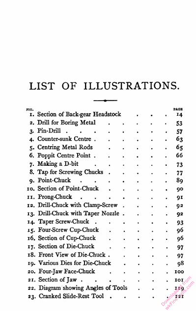
LIST OF ILLUSTRATIONS.
FIG. PAGE
i. Section of Back-gear Headstock ... 14
2. Drill for Boring Metal S3
3. Pin-Drill .... 57
4. Counter-sunk Centre . 63
5. Centring Metal Rods 65
6. Poppit Centre Point . 66
7. Making a D-bit 73
8. Tap for Screwing Chucks 77
9. Point-Chuck 89
10. Section of Point-Chuck 90
11. Prong-Chuck 9i
12. Drill-Chuck with Clamp-Screw 92
13. Drill-Chuck with Taper Nozzle . 92
14. Taper Screw-Chuck . 93
15. Four-Screw Cup-Chuck 96
16. Section of Cup-Chuck 96
17. Section of Die-Chuck . 97
18. Front View of Die-Chuck . . 97
19. Various Dies for Die-Chuck . 98
20. Four-Jaw Face-Chuck . 100
21. Section of Jaw . . 101
22. Diagram showing Angles of Tools . 119
23. Cranked Slide-Rest Tool . . . 121
Downlo
aded
from
wkFine
Tools
.com

Xll LIST OF ILLUSTRATIONS.
FIG. PAGE
24. Round-Nosed Slide-Rest Tool . . . .121
25. Side Cranked Slide-Rest Tool . 122
26. Knife-Edge Slide-Rest Tool 123
27. Parting Tool for Slide-Rest 123
28. Spring Tool for Slide-Rest . 125
29. Inside Turning Slide-Rest Tool . "5
30. Cutter-Bar for holding Gravers . 130
31. Straightforward Cutter-Bar 131
32. Cutter-Bar for Parting Tools 132
33. Cutter-Bar for Inside Turning 134
34. Swing-Bar Overhead Gear . 140
35. Revolving Shafting Overhead Gear 143
36. Template for dividing Band iS4
37. Temporary Division Peg . 1S6
38. Enlarged View of Division Peg . iS8
39. Knob for Division Peg 158
40. Section of Adjustable Division Peg 159
41. Drilling-Spindle .... 161
42. Top of Vertical Cutter-Frame*75
43. Front of Vertical Cutter-Frame . 176
44. Locking-Nut for Cutter-Spindle . 178
45. Hooked Tommy 178
46. Screw-Collet for Cutter-Spindle . 179
Downlo
aded
from
wkFine
Tools
.com
LATHE-WORK.
CHAPTER I.
THE ART OF TURNING.
Its importance and antiquity— Primitive methods of turning—The
potter's wheel—Early forms of the lathe—Its development—
Lathes on standards—Fly-wheels—Literature of the art—
Modem lathes.
Of all the mechanical arts none can claim a more
important place than that of turning, and the
practice of this branch of mechanical manipulation
is capable of developing the highest skill and
intelligence of the artificer. The lathe, which has
been dubbed the father of mechanism, has claimed
the close attention of statesmen and philosophers ;
even monarchs have sought recreation in the
practice of turning. Skilled artisans, who depend
largely on the lathe for the production of their
work, enjoy to an extent a superior position in
their sphere of life, whether they be engaged in
fashioning the rough wares made on the potter's
wheel, or the highest and most refined specimens
of turnery, which are probably to be found in the
/
Downlo
aded
from
wkFine
Tools
.com

2 LATHE-WORK.
finest grades of chronometric art. We disregard
those extraordinary productions of skill and taste
which come from the hands of the amateur turner,
who uses for the production of a fragile gewgaw
tools and appliances that only affluence can afford.
The date of the origin of turning is lost in anti
quity. Probablylongbeforehistorians began to write,
the lathe—in aprimitive form—was known and used,
the potter's wheel being, perhaps, the primogenitor.
The savage's process of kindling fire by twirling a
stick against another piece of wood gives the
motion now used for the alternating drill, and for
small lathes driven with a drill bow ; how this
motion developed into the continuous one of the
potter's wheel we can but surmise. The sym
metrical cylinder is to be found throughout nature,
and art in its desire to reproduce the admirable
form has developed the turning lathe.
The Bible affords a distinct reference to the
potter's wheel ; we read that about five hundred
years before the Christian era Jeremiah went down
to the potter's house, " and behold he was doing a
work on the wheel, making a vessel of clay with
his hands." The use of the lathe, however, dates
long prior to this, and the manufacture of pottery
ware is frequently spoken of in sacred history.
Amongst the relics of antiquity unearthed from the
buried Egyptian cities are numerous specimens
bearing unmistakable evidence of having been
wrought in the. lathe.
The lathe used by the Orientals for generations
Downlo
aded
from
wkFine
Tools
.com

PRIMITIVE LATHES. 3
consisted of two short posts driven into the ground ;
a nail driven through each formed the centres on
which the work revolved, actuated by a drill-bow.
The work was thus only a few inches from the
ground, and the operator in his accustomary posi
tion—squatting on the ground—was able to use
his toes in assisting the application of the tools.
The Orientals use the toes as deftly as they do the
fingers in many of their handicrafts. At the
Paris Exhibition of 1867 a group of aborigines were
working in this manner with the lathe just de
scribed, displaying considerable skill in using
these primitive appliances, and producing work of
intricate and elaborate patterns, chiefly ornamental.
Lathes of this primitive form it would appear are
employed at the present time by the native turners
of India. The skill of the Hindoos in the mechani
cal arts and in the delicate fashioning of ivory and
metal is universally appreciated, and that they
should succeed so well with such rude tools is a
proof of their natural aptitude. The turner of India
carries on his vocation in the style of our itinerant
tinker; he carries all his tools, lathe included,
about with him, and when he gets a job establishes
himself near the door of his employer's house.
Assisted by his boy, the turner fixes up his lathe,
consisting of two posts driven into the ground, as
described previously. The work is mounted
between the centres, a rope is passed twice round
it, and the boy, by pulling each end of the rope
alternately, gives motion to the work, the workman
Downlo
aded
from
wkFine
Tools
.com

4 LATHE-WORK.
guiding the edge of his tool with his toes only, the
handle being held by the hands at some distance
from the work, both man and boy invariably
squatting on the ground, as is the national custom.
Many nations in all parts of the globe employ a
lathe somewhat resembling, but still an improve
ment on, the one just mentioned. This lathe has a
frame so that it is complete in itself, yet it has to
be fixed to the ground for use ; it consists of two
cross pieces held together by a tie-bar on which
they slide, and may be wedged as required. The
cross pieces have iron spikes fitted to them to form
centres, the work is put between these, and they are
fixed by wedging on the tie-bar. The lathe is laid
on the ground and secured by means of a few
spikes, a straight bar of wood is laid across the
cross pieces as near as convenient to the work, and
forms a rest for the turning tools. This form of
lathe is still largely used in Spain, Egypt, and
other places ; the pattern can be traced back
to the Moors, who introduced the lathe to Spain.
The Spaniards in migrating took with them the
lathe and the art of turning, and thus in those
parts of the American continent that Spain has
populated the lathe is found made as last de
scribed.
The continuous motion of the fly-wheel, which
had been employed by the potter from the earliest
times, was not used in the lathes of the ancients,
who only had the alternating revolutionary motion
derived from the bow. When introduced into the
Downlo
aded
from
wkFine
Tools
.com
EARLY LITERATURE. 5
workshops of the Western nations, the lathe was
modified to suit their customs, and whilst the
Orientals kept their turning appliances low, to suit
their habitual squatting position, Europeans
mounted the same contrivance on a framework to
bring it to a convenient height to work at when
standing. This altered arrangement allowed the
bow worked by hand to be replaced by a flexible
pole fixed overhead, from which a cord descended,
and after passing round the work it joined
a treadle, which was worked by the foot ; then both
hands were at liberty to manipulate the tools.
A picture published in a German book in the
year 1568 shows a turner working a sphere in a
lathe ; a quantity of turned objects are lying on the
bench and about the workshop. This illustration
seems to be the first record of the lathe mounted on
standards, and we see by it that the pole lathe was
in use at that date. In books of about the same
period different kinds of lathes are mentioned, but
the cord up to this time appears to have been used
round the work itself, which always had to run
between centres. It is difficult to decide precisely
when the independent mandrel came into use.
The first book devoted to the art of the turner
was published at Lyons in 170 1 ; it was written by
Plumier, and probably did much for the art by
placing before its votaries a record of the condition
that it was then in. That there was a demand for
this ponderous book appears evident from the fact
of a second edition having been published in Paris
Downlo
aded
from
wkFine
Tools
.com

6 LATHE-WORK.
forty-eight years afterwards ; in the interim nothing
was done to enrich the literature of the turner.
Bergeron's valuable book, consisting of three
volumes lavishly illustrated, and containing a vast
deal of information, valuable even at the present
day, was next published in 1792, nearly a century
after Plumier's first edition. Bergeron himself was
a manufacturer of lathes and other tools used by
turners, and probably in writing his book he was
partially influenced by commercial considerations
outside of the book itself. However, some of the
information there given is equally applicable to
tools now used in some cases in improved forms.
The improvements made in many appliances con
nected with turnery since Bergeron's time, however,
place his book at a disadvantage, some of the
arrangements admirably sketched by him being
now obsolete. Soon after this other Frenchmen
wrote books on turning, the most notable being
those of MM. Pauline Desormeaux and Dessables.
Holtzapffel's treatise on mechanical manipula
tion, which was intended to be comprised in six
volumes, the first of which appeared in 1847, is the
most important work on the lathe in the English
language, and its value is universally acknowledged.
Three volumes only were published during the life
timeofthe author, and itwas thought that the remain
ing three would never be issued. The fourth volume
has, however, recently appeared as a posthumous
work, and the other two may yet see light. The
price of this work places it beyond the reach of the
Downlo
aded
from
wkFine
Tools
.com

MODERN LATHES. 7
majority of mechanics, a circumstance much to be
regretted.
The modern lathe in its various forms, from the
tiny tool used by the watchmaker, worked with a
slip of whalebone for a bow and a horsehair for a
cord, on which he fashions with a graver pivots of
correct proportion and precise form on axes that are
themselves sometimes less than one-hundredth of
an inch in diameter and weigh but a grain, to the
leviathan machine, itself weighing sometimes up
wards of 60 tons, and large enough to take in work
of 20 to 30 feet in diameter, and double that
length, is, therefore, the result of continuous im
provements, from at least the time of Jeremiah,
nearly 2,500 years ago.
The employment of cast iron as a constructive
material for lathes at once gave a great impetus to
machinery of all kinds. The planing machine used
for iron, itself an outgrowth of the lathe, did for
flat surfaces what had already been done on
cylindrical work, and it is to the judicious use of
the lathe and the application of its modified func
tions that the present degree of accuracy has been
attained in the manufacture of every grade of
machinery.
Downlo
aded
from
wkFine
Tools
.com

CHAPTER II.
THE FOOT LATHE DESCRIBED.
Its various forms and sizes—Watchmaker's lathes—Bench lathes—
Iron beds of various forms—Back-gearing—Slow motion—Screw-
cutting motion—The lathe best suited for general purposes—The
i framework, bed, and fly-wheel—Mandrel headstock—Back-centre
headstock—The hand-rest and collar-plate—Testing a lathe.
The foot lathe is the tool to which we confine our
selves throughout this treatise, as it is by far the
most generally adopted, though in factories where
heavy work is done and steam power available the
foot lathe generally is superseded by a similar
tool driven by steam. The ordinary form of foot
lathe is too well known to need minute description.
Speaking roughly, it may be said to consist of a
bed, supported at a convenient distance from the
ground, carrying the headstocks. Beneath the bed
a fly-wheel is fixed to revolve freely, and to the
cranked axis of this wheel a treadle is attached.
The motive power consists of the muscular force of
the leg applied to the treadle each time that this
falls on the revolution of the fly-wheel, the weight
of this wheel being sufficient to cause it to revolve
by its own momentum during the time when
power cannot be applied through the treadle. A
Downlo
aded
from
wkFine
Tools
.com

SIZES OF LATHES. 0
band from the fly-wheel to the mandrel conveys
the motion, and in this simple contrivance are the
elements of a foot lathe.
The size of a lathe is described by the height of
its centres—that is, the distance from the centre of
the mandrel to the top of the bed. In other words,
the height of centre is just half the diameter of the
largest circle that will revolve in the lathe, thus
the face-plate is usually a safe guide to the size of
a lathe. The length of bed has much to do with
the bulk, and to a certain extent with the capa
bilities of a lathe ; for, though increasing the length
of bed does not increase the capacity of a given
lathe so far as diameter is concerned, yet the
length of work which may be wrought on it is
increased usually by about the amount of the
added length. The length of bed decides the
length of material that can be turned, whilst the
height of centre governs the diameter; thus, a
lathe on which discs of 40 inches diameter can be
turned with ease is often incapable of receiving a
cylinder of even 6 inches in length, and the lathes
used for turning shafting, perhaps 40 feet long, are
commonly not more than 6 inch centre.
Lathes over 6 inch centre are seldom driven by
foot power, the exertion being too great for one
man who has also to manipulate the tools. From
a commercial point of view it is found to be
more economical to employ steam power rather
than an assistant to help tread the lathe. This
latter expedient is a common practice in small
Downlo
aded
from
wkFine
Tools
.com

10 LATHE-WORK.
workshops where mechanical power is not avail
able. The heavier lathes of 6 inch centre are also
generally driven by steam, but some very light
ones used by wood turners are driven by the foot,
even though they are 7 or 8 inch centre. The
hand-driven fly-wheel is generally used as the
source of motion by those wood turners who do
not employ steam power.
The smallest lathe is that used by watchmakers ;
motion is given to the work by means of a bow, the
lathe is held in the jaws of the bench vice when in
use. The clockmakers' throw is rather larger ; it is
driven by a hand-wheel, and has always dead
centres ; a small pulley on the left headstock, having
a projecting pin to catch the tail of a carrier, being
used to drive the work. The smallest of foot
lathes has generally a bar-bed, of triangular sec
tion, and may be from 2 to 3 inch centre, and is in
general arrangement similar to the throw, except
that it has a revolving mandrel driven by a foot-
wheel, and consequently some modifications are
essential.
Bench lathe, or table lathe, is the name given to
all those which, complete in themselves, fix on any
bench that may be convenient. Lathes up to 4 inch
centre having beds up to 3 feet in length are
usually mounted on small standards about 3 or
4 inches high, and by these they may be screwed
down to any bench. The fly-wheel for driving these
lathes will have to be fixed beneath quite inde
pendently of the lathe bed and headstocks. Beds
Downlo
aded
from
wkFine
Tools
.com
LATHE BEDS. II
of any sectional shape may be used for bench
lathes, but the triangular bar is most in favour
for small ones and is a most suitable form of
bed. The triangle is placed with one angle upper
most, the two upper sides are wrought quite
true and straight, the whole of the headstocks and
fittings are adjusted to these sides, the lower face
being that on which all the clamping screws take
their bearings. Small screw-cutting lathes have
sometimes a triangular bed cast with a groove
along the lower surface, in which the leading screw
lies protected from any falling dust and shavings
made in turning. A peculiarity about triangular
bar lathes is that the mandrel headstock is invari
ably made of two distinct pieces, one taking the
tail-pin and the other the collar, each fixed inde
pendently on the bed. Though able to withstand
considerable downward pressure, the triangular
bar cannot resist torsion so well as the usual form
of bed.
Lathes of 4 inch centre and upwards have gene
rally a cast-iron bed, the top surface of which is
planed to take the headstocks, &c. The most
usual forms of fitting are the V and flat and the
double flat. In the former the V-shaped bearer is
the surface which guides the movable fittings when
shifted along the bed, and in the latter the con
tinuity of the line of centres is insured by having
parallel tenons on the bottom of each piece, fitting
without shake along the inner edges of the bed.
Occasionally the outer edges are planed true ; the
Downlo
aded
from
wkFine
Tools
.com

1 2 LATHE-WORK.
side shake of the headstocks, &c, is prevented by
strips screwed to their base and fitting the outer
edges of the bed. This latter plan may offer some
advantage in being easier to fit, but is not nearly
so accurate as that of fitting the tenon to the
inner sides. Some beds have a break or gap near
the fast headstock, allowing large discs to be turned,
but this is not desirable for ordinary use. The
beds of lathes of this size are usually bolted to iron
standards which carry the centre points on which
the crank revolves, and also those on which the
treadle oscillates. To prevent spreading at the
base a stretcher-bar connects the standards at the
back; and in some cases the front feet are similarly
braced by means of a flat bar of iron lying close to
the ground so as to be out of the way of the feet
and the foot-board of the treadle.
Back gear is an arrangement of wheel-work by
which a very slow motion is imparted to the man
drel ; it usually consists of a wheel and pinion on
the mandrel and a wheel and pinion on a shaft
revolving parallel with the mandrel. Instead of
fixing the pulley on the mandrel it is allowed
to run loose with its front edge close to a toothed
wheel which is keyed to the mandrel ; a nut pre
vents the pulley getting away from this wheel.
A pinion is fixed to the small end of the pulley on
the mandrel, gearing into a wheel fixed to an axis,
which also carries a pinion gearing into the wheel
fixed to the mandrel. Thus on turning the pulley
motion is conveyed to the mandrel through the
Downlo
aded
from
wkFine
Tools
.com

BACK-GEARED HEADSTOCKS. 1 3
wheel-work, and by this means the speed is usually
reduced to one-ninth; nine revolutions of the
pulley produce but one turn of the mandrel. For
ordinary purposes the back shaft is thrown out of
gear; the pulley is then attached to the wheel,
keyed to the mandrel, by means of a sliding bolt.
The illustration, Fig. i, shows a horizontal sec
tion of a back-geared headstock. The mandrel
runs in double bearings, and its tail-end is pro
longed to form a stud, on whieh change-wheels for
screw-cutting purposes are placed. Referring to
the mandrel, and commencing at the right-hand
end, first comes the nose, on which chucks are
screwed, immediately behind it the shoulder, and
then a conical part, forming the front bearing.
Against a shoulder the wheel keyed to the man
drel is shown ; the pulley and pinion solid with it
revolving loose, except when attached to the wheel
by the bolt arrangement. Behind the pulley is a
nut, shown in section, and a washer, made of hard
steel, fitted tightly to the mandrel. This washer,
bearing against the collar in the casting, takes the
back thrust in boring and such operations. That
part of the mandrel passing through the collar is
coned to form the back bearing ; a washer comes
next this, being secured by a nut, as shown. The
end-shake of the mandrel is regulated by the
adjustment of the nuts on each side of the back
collar. The stud forming the tail-end has a key
fixed to it, shown white in the illustration.
The back spindle is a plain steel arbor carrying
Downlo
aded
from
wkFine
Tools
.com

14 LATHE-WORK.
a wheel and pinion securely fixed together, and
tight on the spindle. In the position shown in
Fig. i the wheel and pinion are out of gear with
those on the mandrel. A peg put into the hole in
the casting (see left-hand end) prevents the back
Fig. i,—Plan Section of Back-gear, Double Bearing, Screw-cutting Mandrel
Headstock.
spindle shifting and getting into gear. When it
is desired to put the wheels in gear the peg is
withdrawn, the spindle moved towards the left
till the right side groove is under the hole. The
peg is then replaced to keep the spindle in its new
position. The mandrel-wheel and pulley are at
Downlo
aded
from
wkFine
Tools
.com

OBJECTS OF BACK-GEAR. 15
the same time disconnected to allow the gearing
to act.
Though back-gearing is undoubtedly a very
valuable auxiliary to a lathe on which much heavy
metal turning is done, yet for most purposes an
arrangement of slow-motion bands will suffice.
By this means the constant noise and jarring
accompanying the use of wheel-gearing is done
away with. Much smoother work is produced
by having a strong gut band from a small
pulley on the crank shaft to a large one on the
mandrel. When these two pulleys are of equal
size it is possible to turn up a cast-iron face-plate
of the full diameter that the lathe will take, and by
putting a pulley of half the diameter on the crank
shaft such a job could be accomplished with toler
able ease. Such heavy work is, however, usually
done by steam-power, and all the power that can
be judiciously got out of a foot lathe is usually
obtainable with simple slow-motion bands.
The slide-rest is an attachment of so much im
portance that an entire chapter is devoted to the
description of its varieties and merits. The chief
object of this—all that need here be mentioned—
is to form a perfectly rigid tool-holder, which, hold
ing the tool mechanically, does not allow the ine
qualities of the work to exert so much influence as
is unavoidable in hand turning ; moreover, guid
ing the tool mechanically, it does so with a precision
unattainable in hand-work.
Screw-cutting lathes are those which, by an
Downlo
aded
from
wkFine
Tools
.com

1 6 LATHE-WORK.
arrangement of wheels receiving motion from the
mandrel and conveying it to the leading screw,
move the slide-rest along the lathe bed at a
uniform rate, so that a tool fixed in the rest will
cut a regular spiral on the surface of a cylinder
revolving between the centres. By arranging the
wheels which transmit the motion from the man
drel to the screw in relative proportions, the rate
or pitch of the thread cut on the work may be
coarse or fine to any degree within the com
pass of the wheels available ; these are called
change-wheels, twenty-two usually constituting the
set.
The leading screw itself revolves, in bearings
attached to the bed, sometimes inside but gene
rally on the near side of the bed ; the end to
wards the mandrel projects and is made to take
the change-wheels. A slotted arm called the wheel-
plate, swinging round the screw, carries one or
more studs on which the change-wheels also fit,
the piece of mandrel projecting at the tail-end being
similarly shaped ; and thus a wheel on the leading
screw, another on the stud, and another on the
mandrel make a combination producing an effect
proportionate to their relative diameters. The
slide-rest is fitted with a clutch gearing into the
leading screw and forming a nut, which may be
detached instantly. A screw-cutting lathe not only
enables one to cut threads of any rate and diameter
perfectly true, but it is also available for working
as a self-acting machine when turning cylinders,
Downlo
aded
from
wkFine
Tools
.com

FIVE-INCH CENTRE LATHE. 1 7
the rate of screw then being cut amounting to
nothing more than a regular feed.
It is unnecessary, in this treatise, to speak of the
more uncommon modifications of lathes, which fit
them for special purposes and are not of general
interest. The next consideration will be, What is a
suitable lathe for general use ?
Probably the requirements of each individual
reader will have certain peculiarities which it is
quite impossible to take into consideration when
treating of the subject in a general manner. For
small work in metal a heavy 4-inch centre lathe
will be useful, whilst for working in wood a light
6-inch would be more appropriate. Brass work
requires quick speeds, which are best maintained
with a light lathe ; but heavy iron and steel work
is wrought at a slow speed on a heavy substantial
tool. The exertion required to drive a 6-inch
lathe will be much more than that necessary for a
smaller lathe of similar calibre, and thus it is but
a waste of energy to employ a lathe unnecessarily
large.
For general purposes a 5-inch centre lathe will
be found most handy, the height of centre allowing
a wide range in diameter. Then, if the mandrel is
moderately light, without back-gear it will be strong
enough to take the heaviest work that can be done
on a 4-inch lathe, with the advantage of offering
facilities for turning wood and light material of
much larger size. The bed may be 3 feet 6 inches
to 4 feet long, allowing lengths of 2 feet to 2 feet
c Downlo
aded
from
wkFine
Tools
.com

1 8 LATHE-WORK.
6 inches between the centre points. The con
venience of the longer bed consists principally in
having the poppit headstock or slide-rest out of the
way when either of these is pushed to the end.
With short beds it is sometimes necessary to remove
the slide-rest or poppit in order to get at the work
conveniently, and this is some trouble.
A heavy bed, bolted to substantial standards, is
most desirable ; the bed for a 5-inch should measure
about 4 inches in width and depth ; if a double flat
the central space may be about i| inch wide, leaving
each flat a trifle wider. A 4-feet bed should weigh
at least £ of a cwt. The fly-wheel of such a lathe
should have series of grooves in steps correspond
ing with those of the mandrel pulley, so that the
band may be shifted to any grooves on a series, and
fit taut without any readjustment of length ; there
should be two series of grooves, for each a special
length of band being necessary. The extreme
diameter of the wheel may be 24 to 26 inches, with
a series of three or four grooves graduated from the
largest possible size. The second series would be
about half that diameter, and have but two grooves ;
in cases where the suggestion before made of
having a small pulley for slow motion is adopted
this may be from 4 to 6 inches in diameter. Fly
wheels are generally too light ; £ of a cwt. is not
any too heavy for one 24 inches in diameter. The
crank shaft should be i£ inch diameter, and if
4 feet long, two cranks are advisable, as they sup
port a long treadle better than a single crank,
Downlo
aded
from
wkFine
Tools
.com

MANDREL HEADSTOCKS. 1 9
which is, however, quite enough for one 3 feet 6 inches
long. The ends should always be plugged with
hardened steel, and drilled up properly before being
countersunk ; the end should then be turned down
conically to meet the edge of the countersink, so
that when in position and running the oil applied
to lubricate will not be thrown away from the
centres by centrifugal force. This is an important
point, though constantly neglected by lathe-makers.
By observing a crank-shaft with flat ends it will be
seen that the oil, applied to the centre, quickly
spreads over the face and runs away from the bear
ing—when the crank is still, by gravity, and when
revolving, by centrifugal force. The wheel is usually
fixed to the shaft by keying, though sometimes it
is secured against a shoulder on the shaft by means
of a nut. The points on which the axis revolves
should be so adjusted that though the bearing is
quite free there is no shake whatever, and the
position of these points must be such that the crank
shaft runs parallel with the lathe bed. The wheel
itself must be fixed perfectly true, and in a vertical
line under the mandrel pulley.
The headstock of a plain lathe, in which the man
drel runs—called the mandrel headstock, or fast
headstock, to distinguish it from the movable or
poppit headstock, which takes the back centre—
should have a deep tenon cast on the bottom, to
make the casting rigid ; the upper side should
be hollowed out to allow freedom for a large pulley,
which for a 5-inch lathe may be 8i inches in dia
Downlo
aded
from
wkFine
Tools
.com

20 LATHE-WORK.
meter. The length of the mandrel adds much to
the steadiness in turning, provided always that
only the smallest possible amount projects from
the collar at the nose end. A mandrel, 8 inches
long, is a good proportion, and would be spaced
thus : the thread of the nose, f inch long, cut with
a f inch Whitworth thread ; cone for front bearing,
i inch long, the diameter being about i| inch,
tapering about i° ; plain part, ij inch long, i$ dia
meter; pulley, 2^ inch ; washer, nut, and plain part
behind pulley 2 inches, with a small part J inch long,
terminating in a cone point. The headstock for such
a mandrel would be 10 inches long at the base, with
a portion of the boss which holds the tail-pin
projecting about ^ inch to the rear, the total length
of the hole in which the tail-pin fits being fully
2 inches; the tail-pin should be cylindrical, per
fectly true, and fit the hole tightly, being held by a
nut on each end. Tail-pins, which are themselves
screwed through the casting and fixed with a lock
nut should be invariably avoided, as with such the
countersunk hole, bored in the centre, is sure to be
eccentric when turned in the thread, and thus the
axial line of the mandrel would be continually
altered. That the headstock casting fits the bed
properly is most essential ; in many cases it will be
found that the casting gets bent on the holding-
down bolt being screwed tight, thus throwing the
boring of the collar-hole and the tail-pin hole out
of continuity. A direct pull by one bolt, near the
centre, so often bends the casting that it is
Downlo
aded
from
wkFine
Tools
.com

POPPIT HEADSTOCKS. 21
advisable to hold it down by two bolts, one near
each end.
The back centre headstock should always be bored
out quite parallel and in a direct line with the axis
of the mandrel, the barrel being cylindrical, with a
groove along it in which a T-headed blank screw,
dropped into a hole in the casting, fits and prevents
the barrel rotating. The screw which actuates the
barrel is usually made with a left-handed thread,
for convenience in turning, but whether left or right
handed is perfectly immaterial, except for the con
venience. For turning the screw a hand wheel or
a winch handle is used ; the former is more con
venient for boring with, and the latter offers the
advantage of not being so much in the way. An
arrangement for clamping the barrel at any desired
place always forms part of the poppit head, and if a
screw acting direct on to the cylinder is used, a disc
of brass or other soft metal should be interposed to
save the barrel from being dented. The point of
the poppit cylinder is always removable ; sometimes
it is fitted by screwing into the barrel; but another
and far better plan is to fit it in conically. The cone
fitting is as tight as any—in fact some lathes have
conical noses, on which the chucks fit by simply
pressing on, and they then jamb. A cone fitting to
the back centre offers great facility for shifting the
point, an operation which sometimes has to be done
constantly. The screw inside the poppit barrel
should be sufficiently long to allow the tail end ofthe
point to be made long enough to touch when the
Downlo
aded
from
wkFine
Tools
.com

22 LATHE-WORK.
barrel is drawn back, and thus the point is forced
out by simply winding back the cylinder. Several
points should be fitted to the back centre, and some
pieces with flat ends for boring against ; these are,
however, spoken of in another chapter. The dia
meter of the barrel may be an inch, the cylindrical
part of the casting into which it fits being about
i % inch in diameter. The barrel is bored out from
the front end large enough to clear the thread of
the screw by which it is moved, to within halfan inch
or so of the back end ; this part is tapped to fit the
screw. The lateral motion of the screw is confined
by having a collar on it, which on one side bears
against a loose washer resting against the end of
the casting, and on the other against the cap
screwed on to the casting. The handle on the end
of the screw should not confine its lateral motion,
and it is often merely pushed on a square or hexa
gonal fitting, though sometimes secured by a key
or a nut.
The hand or T-rest needs but little comment ;
the socket should be bored at right angles to the
sole, which should be planed with a dovetailed slot.
If the lathe bed is double flat the sole of the hand-
rest stands direct on it ; if a V-bed it should have
a cast-iron foundation plate, shaped to fit the bed
on the under side and flat on the top. The screw
which clamps the T should have a handle like
that of a bench vice fitted to it, as it so often requires
to be shifted to suit the work in hand. A " per
manent tommy" is also desirable in the screw
Downlo
aded
from
wkFine
Tools
.com

HAND-RESTS. 23
which clamps the back centre barrel, as it is so
much more handy to be able to fix these parts
without the trouble of finding the "tommy" on
each occasion.
The T itself for general use may be about 2 inches
long on the top and should be flat and level ; in use
it will be continually pitted, and must be filed up
smooth again. For turning long cylinders by hand
a much longer T is used, measuring as much as 5
or 6 inches. For still longer rods it is customary
to use a straight bar as a rest, which is supported
near its ends in two T socket-holders ; by this plan
a rest, reaching the entire length of the bed between
the centres, can easily be fitted up. In turning
work of short length the X-rest is sometimes found
to be in the way, and a "I -rest is used instead; this
is made of an angle piece, one leg fitted to the rest
socket, and the other filed flat on that surface form
ing the top. The "J-rest is often used with the point
towards the work, thus giving a rest of about £ of
an inch in length, very convenient for short work.
y and "1 rests are usually made of cast iron, but
wrought iron is sometimes used, and this is the
better material, especially for the latter shape.
A collar-plate is an arrangement in general use
for supporting the ends of rods whilst these are
being bored up ; it consists of a disc of cast iron
having a quantity of holes bored near its edge.
These holes are very much coned and are graduated
in size ; in use the largest side is put towards the
mandrel, and the bar being turned revolves in the
Downlo
aded
from
wkFine
Tools
.com

24 LATHE-WORK.
conical hole as in a collar. The plate is fixed by
its centre by means of a bolt clamping it against a
dwarf casting. The work before being put in the
collar-plate has its end turned true, and the extreme
edge rounded off to prevent its cutting the plate, a
drop of oil being applied to lubricate the bearing.
The axial continuity of the work is preserved by
placing the back centre against it before finally
adjusting and fixing the collar-plate, which is
screwed tight at such a position that the work turns
freely without shake. On removing the poppit head
the centre of the end of the bar may be operated
upon as required ; it may be bored up with a
drill and the hole then enlarged and made true
with a tool in the slide-rest, or otherwise treated.
The chief essential requisites of a good lathe are
that the bed should be sufficiently strong to be
quite rigid, and that the headstocks fit it properly
at all parts of its length ; this latter may be tested
by trying them. A bed " in winding " is an abomi
nation, though sometimes to be met with, being
the result of careless chucking in the planing
machine ; through bad bolting to the standards a
bed is sometimes thrown " in winding." For this
defect test with winding strips, which are perfectly
parallel straight edges, by placing them trans
versely across the bed at various places, and notic
ing that the top edges of both are level. The entire
framework of the under part of the lathe should be
strong and firmly braced together standing on four
feet, each touching the floor, so that solidity is
Downlo
aded
from
wkFine
Tools
.com

AXIAL CONTINUITY. 25
imparted to the whole structure. The treadle
should be as low as possible, just to be clear of
the floor when at its lowest point, rising to about
9 or 10 inches. A narrow strip of wood nailed
to the floor just in front of the foot-board of the
treadle will serve as a guard to prevent the toes
from getting underneath.
That the entire line of centres should be perfectly
parallel with the bed is always desirable, and in
many cases absolutely essential for producing true
work. The two ends of the mandrel should be
exactly equidistant from the bed, as should be both
ends of the poppit cylinder. The effect of having
the axis of rotation of the mandrel at an angle
with the bed is not shown when turning between
centres, though the carrier and the pin of the
driver-chuck will be continually rubbing against
each other to an extent proportionate to the error
in the line of centres. The mandrel may be
differently distanced from the bed at one end than
at the other, without affecting the work between
centres, though when chucked without any back
support the free end of the work will be more or
less above, below, or on one side of the back centre
point, as work unsupported will naturally take the
position of an axial continuity of the mandrel
itself.
In order to test the truth of the axis of rotation
with the lathe bed itself, the positions of the
mandrel bearings must be gauged. The paral
lelism of these bearings with the top and inside of
Downlo
aded
from
wkFine
Tools
.com

26 LATHE-WORK.
the bed will be shown by fixing, in a chuck, a bar
of metal as long as possible, to allow the back
centre to stand on the bed with the point clear.
This bar of metal must be centred whilst running
in the lathe, and its centre will, if the mandrel is
parallel with the bed, coincide with the point ot
the poppit ; the bar must be strong enough to bear
its own weight without drooping at the unsupported
end, or the test will show false. Another method
of testing the whole of the holes in the headstocks
is by putting the mandrel head to the right of the
poppit, and reversing the barrel so that it protrudes
at its right-hand end ; then if the point of the poppit
comes exactly opposite the tail-pin .of the mandrel,
or its centre if in double bearings, the continuity of
the axial line of centres is proved to be in a straight
line with the bed.
Another good plan, perhaps the better, is to fit a
hard wood mandrel in the bearings, leaving at
each end, projecting a few inches from the casting,
a cylindrical portion of exactly the same diameter.
Make a template or gauge of sheet metal to show
the distance of these portions from the bed, and
gauge carefully at both ends ; any error will be at
once felt, as the sense of touch is marvellously keen.
This is proved by the ease with which minute
differences, that cannot be detected by the eye,
are discovered by the feel in callipering. Unless a
good light is on the object it is difficult to see
minute errors.
A perfect fit of the mandrel bearings may be
Downlo
aded
from
wkFine
Tools
.com

LATHE-NOSE. 2^
proved by Screwing the tail-pin as tight as possible,
so that the mandrel may be turned by hand, and if
there are no places where the fit is easier than at
others you may consider it accurate, providing that
there is no side shake whatever. The mandrel
must always be kept up to its bearing by the tail-
pin, and never allowed to run loose, or the bearings
will be worn unequally.
The flange of the nose, against which the chucks
screw, ought to be quite flat and perfectly true, so
should the thread of the nose, though it is rather
the exception to find that it is so. Some makers
turn a groove in the mandrel at the back of the
thread, reducing the diameter to that at the bottom
of the thread, though with what reason is not easily
conceivable. The effect is to very materially
weaken the mandrel at that part which is, under the
most favourable circumstances, its weakest place.
The bearing of the mandrel should be of steel and
very hard, and the face against which the chucks
jamb should also be of steel—in fact, a continuation
of the bearing, the usual plan being to shrink a
steel collar on a mandrel of fagoted iron.
If the boring of the poppit headstock is anything
but absolutely true with the line of centres, the
position of the back centre point, relative to the
axial continuity of the mandrel, will be constantly
varying as the poppit barrel is wound out. The
truth of this boring can be tested to a certain
extent by winding out the point as far as possible
without allowing the barrel to become loose in the
Downlo
aded
from
wkFine
Tools
.com

28 LATHE-WORK.
hole, and then testing it with a point-chuck. The
oppositeness of the points cannot be tested by
contact with any degree of accuracy. The best plan
is to use a narrow parallel straight edge and adjust
the cones to that distance apart which just allows
the straight edge to go between them, with its
opposite edges resting against the opposite sides
of the cones. The straight edge is applied on both
sides, above and below, and readily shows the
oppositeness of the points. The poppit may be
gauged in the same way as described for testing
the mandrel bearing with a wooden temporary
mandrel ; using the barrel, which must fit nicely,
projecting at both ends of the casting.
Downlo
aded
from
wkFine
Tools
.com
CHAPTER III.
HAND TURNING.
First principles of the art, commencing to practise—Wood turning,
the gouge and the chisel—The mode of their application to
the cylinder and surface—Easily made objects for beginners—
Making a plain wooden box—Metal turning, the graver and tri
angular tool, and their use—Finishing tools, round nose tools, &c.
When commencing to practise the art of turning
it is advisable to begin by using simple tools and
appliances, and with them to execute work of the
most rudimentary kind, so that the learner may
become properly acquainted with the elements of
lathe-work, and he will then be able to understand
the execution of the more complicated work. It
sometimes happens that a fine collection of tools
comes into the hands of one who has never had
any previous practice in their use, but who will
nevertheless boldly essay to use the most compli
cated machinery before troubling to learn the prin
ciples that govern its application, and which are
only to be studied in using the simpler tools. A
person unacquainted with the conditions under
which a hand-tool acts most favourably, only to be
learned by practice, cannot correctly judge the best
position in which to fix a tool in the slide-rest ; and
Downlo
aded
from
wkFine
Tools
.com

30 LATHE-WORK.
the art of turning, like all others, to be learned
properly must be begun at the beginning. The
first lesson in turning should, therefore, be at a
plain foot lathe with back-centre and T-rest only, all
the apparatus and attachments which have been
described as adapted for special purposes being
removed entirely, for though the slide-rest may be
very useful to assist a beginner in roughing-down
the work, yet it would be most injudicious to
make use of such an apparatus before acquiring a
thorough mastership over hand-tools.
A plain parallel cylinder is, perhaps, the very
best object for a beginner to try his hand at pro
ducing, for its simple form dispenses with all com
plex manipulation of the tools ; yet the produc
tion of a true cylinder can only be achieved after
much practice, and such work demands more skill
than would be at first sight imagined. Any slight
slip of the tool causing its point to dig into the
work would, of course, spoil a cylinder nearly
finished to a definite size ; but for practice such a
mishap would be of no consequence, only necessi
tating the reduction of the entire cylinder to the
size of its smallest diameter. For wood turning
the gouge and chisel are the tools most generally
used, and they will be sufficient for our work ; a
similar cylinder of metal would be turned with a
graver. Soft wood will do for material, though
hard wood is more pleasant to work, and will not
require driving at a high speed, which is tiring
to the tyro. A chuck will be wanted to carry the
Downlo
aded
from
wkFine
Tools
.com

TURNING SOFT WOOD. 3 1
work, and the prong-chuck, described in another
chapter, is best suited to the purpose ; and we will
suppose the rough wood mounted between such a
chuck and the back-centre, which is screwed up to
take firm bearing and the extreme point oiled.
For soft wood turning, place the band on the pair
of grooves giving the quickest motion—that is,
from the largest on the fly-wheel to the smallest
on the mandrel—and in revolving the work it will
be scarcely possible to drive it too quick. The
hand-rest is then adjusted so that the top edge of
the T is on a level with the lathe-centres, and the
work revolves just clear of it. The position for
standing at the lathe whilst turning a cylinder is
with the shoulders fairly parallel with the lathe-
bed, the body upright, resting on one foot, the other
being on the foot-board of the treadle, the operator
using either leg to support him, and occasionally
changing from one foot to the other as he becomes
tired; the foot on the ground is placed as far
towards the lathe as the treadle-board will allow.
With a balanced fly-wheel, that is, one weighted so
that the crank always stands, when at rest, slightly
inclined forward from its highest point, the
treadle will be in the position to receive the pres
sure of the foot. Under ordinary circumstances
the lathe-band is pulled down from the mandrel
or the fly-wheel is revolved by the left hand, so as
to bring the crank into the position described, and
then pressure is exerted on the treadle, and the
work revolves. Two or three strokes are given to
Downlo
aded
from
wkFine
Tools
.com

32 LATHE-WORK.
get up the momentum before the tool is applied to
the work.
The turner's gouge is used for roughing out
wood-work, and a turner should provide himself
with several sizes, according to the work he has to
execute. For general use a gouge half-an-inch or so
widewill be found most serviceable; the tool is sharp
ened differently to the carpenter's gouge, so as to
leave the cutting edge rounded off instead of square
with the shaft of the tool, as in the carpenter's
gouge. The grinding is all done from the outside
of the semicircle, and forms one continuous bevel,
leaving an acute angle for the cutting edge.
Gouges should be fitted into long handles to enable
the operator to have complete control over the tool
when in use. A half-inch gouge may be a foot or so
long from end to end of tool and handle com
bined; larger sizes are much longer, frequently
measuring as much as 2 feet, and sometimes even
more. The gouge is grasped firmly near the
cutting end by the left hand, the knuckles being
uppermost, and is laid on the rest with its curved
side downwards ; the right hand holds the end of
the handle, and usually rests against the side of the
body, to afford greater steadiness. Thus held, the
edge of the gouge is gradually brought sufficiently
near the revolving cylinder to touch it in the posi
tion known as at a tangent to the circle, that is, so
that a line drawn in continuation of the ground bevel
will touch but not cut into the cylinder. In this posi
tion the tool will not cut, but on raising the end of
Downlo
aded
from
wkFine
Tools
.com
USING THE GOUGE. 33
the handle with the right hand the edge of the tool
is depressed, and becomes in the position of a
tangent to a smaller circle, then all the material
outside of that diameter will be shaved off by the
tool. The pressure on the edge during the process
tends to force the tool deeper into the work, and,
therefore, the end held in the right hand must be
kept down till the work has been reduced all round
to the new diameter, when the gouge will again
cease to cut. A slight elevation of the handle
will again throw the edge into the cylinder,
and so on till enough has been removed from the
work.
Though the elevation of the handle has been
described as an intermittant process, yet in practice
it is, of course, a continuous one, for it is by rais
ing the handle that the tool is fed into the work,
the thickness of the shaving being regulated by the
feed thus given. If the theory which governs the
cutting of the gouge is properly understood it will
be easy to carry out the principle in practice, and
thus rapidly acquire proficiency in the use of the
tool. By means of the gouge the rough wood is
turned to a circular form, all the angles are re
moved, and the work made as straight as possible.
A pair of callipers is used to measure or gauge
the size from end to end, and those parts found
to exceed the general diameter are reduced, so that
the surface will be fairly straight. There will, how
ever, yet remain a series of ridges resulting from
the use of the circular-pointed gouge, and these are
Downlo
aded
from
wkFine
Tools
.com

34 ' LATHE-WORK.
shaved off by the use of a chisel applied in a
similar way.
The turner's chisel is a fiat tool similar to the
carpenter's paring chisel, but ground very differ
ently. It is bevelled equally from each side, leav
ing the cutting edge in the centre of the thickness,
at an oblique anglewith the sides of the shaft, instead
of square across, as in the carpenter's chisel, the
angles being usually about 700 and no°. The
chisel is held in the same manner as the gouge, with
the lower corner of the obtuse angle edge placed
on the rest. The chisel is tilted up sufficiently to
bring the central part of the cutting edge against
the work, leaving both corners free, for should the
entire width of the cutting edge be brought to bear
on the work the tool will dig in. With the edge
lying obliquely against the cylinder the chisel
may be slid along the rest with the bottom edge
leading, and the cut taken from either end, accord
ing to which of the two corners of the tool is laid
on the rest. The principles which govern the
gouge apply equally to the chisel, and by a proper
amount of tilt a shaving of any desired thickness
may be removed; the shavings may be so thin
as to produce a barely perceptible difference in the
diameter of the work. "When the ridges left by the
gouge have been entirely obliterated the diameter
of the cylinder is tested by callipering, and any
irregularity can be smoothed off with the chisel.
Capital practice for a beginner will be to take a
shaving from end to end of a parallel cylinder, still
Downlo
aded
from
wkFine
Tools
.com

WORK FOR BEGINNERS. 35
leaving it perfectly parallel after the shaving is
removed. This is not difficult when the manipu
lation of the tool is quite under control ; the thick
ness of the shaving will be the best guide, and this
may be regulated to the greatest nicety by adjust
ing the height of the tool handle held in the right
hand.
The directions here given for using the gouge
and chisel on a plain cylinder are equally appli
cable for turning cones, which are similarly formed
with these tools.
For turning the surface of wood chucked plank-
ways the same tools are used, the T-rest being
placed round to lie parallel with the face of the
work, and the gouge held in a more horizontal
position than when applied to the cylinder. The
chisel is used with its broad surface resting flat on
the top of the T, the whole breadth of the cut
ting edge against the work, but held so that the
corner on the side towards which the tool is ad
vanced barely touches; the action of the chisel
being scraping rather than cutting, though shav
ings are produced.
It is curious that beginners at turning are often
at a loss to find an object on which to practise,
so that, descriptions of a few that can be easily
made will be suggestive of others. Ordinary
round rulers, varying from 6 inches to 2 feet in
length, and from | inch to i£ inch in diameter,
are of very simple form. By following the
directions just given on the use of the gouge
Downlo
aded
from
wkFine
Tools
.com

36 LATHE-WORK.
and chisel it will be easy to turn rulers, and so
gain experience. A roller on which to hang a
jack-towel and a rolling-pin are usually to be
found in every household, and capital practice
will be afforded in turning exact copies of such
things. Cricketers' stumps and bales, tool handles,
trenchers, and numerous other common articles
are made on the lathe. The production of these will
afford variety to the practice and enlarge the range
of work without very severely taxing the skill, yet
always adding to the capacity of the workman.
It is well to remember that an adept at turning
such simple objects will find it easy to proceed to
the execution of the most complicated work. A
plain wooden box affords considerable practice
in the use of hand-turning tools, and the method of
making one is this :—Having decided on the size of
the proposed box, select a piece of wood, almost
any kind will do, but preferably use that which has
a close even grain. See that the ends are cut
tolerably square, and mark a circle on each to
serve as a guide for roughing out the circumference
as nearly round as possible, first with a hatchet, and
afterwards with a rasp. The length of the wood
must be :—the height ofthe box, the height of the rim
on which the cover shuts, the height of the cover
itself, enough space to allow the parting-tool to be
used twice—that is, where the lid is separated from
the body of the box, and where the box is cut from
the superfluous piece in the chuck—and enough to
chuck the wood by. All these measurements added
Downlo
aded
from
wkFine
Tools
.com

MAKING A WOODEN BOX. 37
together show the length of wood required to make
the box. It is important to measure the rough
block to see that there is sufficient material, as it
will be a great saving of labour if the complete
box, lid, and body are turned from one instead of
from several pieces of material.
The roughly-shaped cylindrical block has now to
be chucked firmly on the lathe, it may be fixed in
a cup-chuck if one of convenient size is to be found ;
or a boxwood chuck may be hollowed out, to a
depth of about a quarter of an inch, sufficiently
large in diameter to allow the wood to be driven in
firmly by a few smart blows of a mallet. That end
which is cut most nearly square with the cylin
drical sides should be chosen for driving into
the chuck. It should not be made to bottom,
that is, the block should be driven into the chuck
to touch all the way round. When properly
chucked the end of the wood is first operated upon
with the gouge and turned true ; the tool is held as
described in the early part of this chapter, working
from the circumference towards the centre. When
turned true, the chisel is used to smooth the sur
face and make it fiat; the cylindrical surface of
the cylinder is turned true in the manner pre
viously described for such work, and the rough
block is thus got to a truly cylindrical form,
parallel and square at the end. So far the work
has been only preparatory.
The first operation in making the box itself is to
shape the lid. On the circumference of the cylinder
Downlo
aded
from
wkFine
Tools
.com

38 LATHE-WORK.
mark a ring showing the depth of the intended lid—
this may be done with the angle of the chisel—
then hollow out the front to the required depth, to
leave sufficient thickness of material at the top of
the lid ; a side tool will do this part of the work
most easily. The rim of the lid for the box should
be slightly undercut in both directions ; a very little
will suffice, so that it will fit closer on to the box.
With a wood-parting tool the lid is cut off from
the rest of the wood ; the tool should cut only a
narrow groove, and the direction of this must be
carefully maintained so that the thickness of the
lid will be equal and sufficient for due strength.
Tolerable truth will suffice, as the top of the lid will
be finally finished later on when it is snapped on
the body part, and the top will then face the back
centre. In parting off the wood the groove must
be kept wide enough to allow the tool to be free of
the sides. When getting near the centre extra
care is necessary to guard against the tool catch
ing in and tearing off the lid, in which case the
probable result would be that the breakage would
spoil the lid.
The wood now left in the chuck is to form the
body of the box ; it is first hollowed out to form
the interior, the same tool and the same general
principles as were employed in turning out the
inside of the lid being applicable, the precise
height having first been marked on the outside.
Before removing the entire inside of the box, the
neck part on which the lid fixes must be turned to fit
v
Downlo
aded
from
wkFine
Tools
.com

MAKING A WOODEN BOX. 39
and the lid snapped on tightly. In turning down the
neck, when it nearly approaches the required size, it
is advisable to frequently try the lid on it, other
wise too much material may be removed and the
job spoilt. With experience, however, it becomes
easy to fit without trying the sizes more than once.
There should not be the slightest play or shake in
the fitting, the rim should be quite true cylin-
drically and the shoulder equally true flatways, so
that when the lid is put on and gently forced to its
place the join should be absolutely imperceptible
but for the appearance of the grain of the wood.
With the lid fitting tightly it can be turned up
true with the chisel, comparatively light cuts will
only be necessary as the work has already been
made true. The cover may be slightly dome-shaped,
and the side of the box should be turned with the
chisel to make it and the lid perfectly coincident.
- With the parting tool the box may be now par
tially cut off from the remaining piece of waste
wood, but before being entirely detached the ex
terior ought to be finished. The turning chisel, if
properly handled, will leave a surface that will be
difficult to improve upon, but if any roughness exists
it may be smoothed with fine glass-paper. The
inside of the box is also finished before the parting
tool finally cuts it off ; the sides are made straight
and the bottom flat and then the box body is cut off,
the parting tool being held at a slight angle to the
axis of rotation so as to slightly undercut the
bottom which will then stand firmly on its edges,
Downlo
aded
from
wkFine
Tools
.com

40 LATHE-WORK.
and requires no further treatment. If it is desired
to turn the bottom face, the piece of waste wood
can be hollowed out so as to fit the rim on which
the lid fits, and chucked by this the bottom may be
operated upon as required, leaving it slightly con
cave. Every time that the box or lid is re-chucked
it must run as true as it did in its former position,
and to re-chuck work perfectly true is one of the
first lessons that a turner should study. There
are also the fittings of the lid to the box and the
box to the chuck, which will be excellent practice.
It may be assumed that when a plain box, in
common wood, can be turned out of hand in every
respect well made, the maker has attained sufficient
skill in the use of his tools to warrant his under
taking without fear of failure work of far more
complicated design and apparently more difficult
to execute. The plain box just described is scarcely
a piece of work likely to attract the attention of
those who have an extensive assortment of tools
and appliances ; still the care and attention which
must necessarily be bestowed on the various opera
tions incidental to its production afford an amount
of practice in the use of hand tools on wood which
is considerable and varied, and should be prized
accordingly.
Turning metal by means of hand tools is a
process in every way similar to that just described,
modified to suit the nature of the material. It is
generally found that an inexperienced hand suc
ceeds better in turning metal than wood ; there is,
Downlo
aded
from
wkFine
Tools
.com

THE GRAVER. 4 1
however, no more difficulty in working this latter
material, and the circumstance named is due to
the more obvious effect produced with wood, making
it much easier to see the effect of the tools used,
but more difficult to guide them. Wood is turned
at a far greater speed than is metal, and the
material is much softer, so that whilst the tool
more easily penetrates the work and " catches in,"
this is more liable to be torn than the more
tenacious metal revolving at a less velocity.
The same angle is to be preserved in applying the
tool to metal, that is, it should form a tangent to the
circle being cut, but consequent on the hardness of
the material the angles of the cutting edges must be
altered to make them stronger; however, the work
man who, by practice on wood, makes himself
familiar with the most favourable conditions under
which the tool acts, will be best able to apply tools
to metal to the greatest advantage.
The graver is the most general tool for metal
turning. It is a bar of square steel, usually about
one-quarter to five-sixteenths of an inch in size,
though smaller and larger are used. All the flats
are sometimes, but two are always, ground flat
and smooth. The end is ground off diagonally,
those edges formed by the sides meeting at the point
being used for turning. The angle made by the
diagonal diamond - shaped end with the shank
varies to suit the material that it is intended to act
upon, from 60° to 700 being about the usual limit.
The triangular tool is also much used. It is
Downlo
aded
from
wkFine
Tools
.com

42 LATHE-WORK.
generally made from a worn-out triangular file, of
the dimensions named as usual for gravers, and
is merely ground on the faces to take out all the
marks of the file teeth, leaving sharp edges at the
angles, all of which are 6o°. The end is ground
off obliquely, leaving a point at one angle, but the
tool is generally used to cut with its side edges ;
and in this respect it principally differs from the
graver, which is used only at the end.
"With the two tools named most of the rough
turning by hand on metal is done. Tools for metal
have short handles. In use the left hand generally
grasps the T-rest and the tool, the fingers encir
cling the stem of the rest socket and the thumb
clasping the tool to the T. The right hand holds
the handle as described in holding wood-turning
tools ; indeed, sometimes both hands are used as
there described, only closer together, a natural
consequence on the reduced length of the handle
and tool itself. A lubricant is used with these
tools on wrought iron and steel ; this is necessary
to keep the edge cool and lubricate the cutting.
Water answers the purpose, but soapy water is
better, and perhaps quite as good as oil, though
much cheaper. Cast iron, brass, and gun-metal are
turned dry.
The way in which the graver is applied to the
work is this :—the tool is laid with one angle on the
T-rest, the point being towards the back centre,
and the handle at an angle with the line of centres.
The lathe being set in motion and the graver
Downlo
aded
from
wkFine
Tools
.com

TURNING METAL. 43
brought as near as possible to the work, it is
firmly indented on the rest, and by bringing the
handle towards the right the point is made to cut
the work ; the operation is assisted by turning the
graver slightly over towards the left. This action
makes a narrow groove on the work, and when the
handle is so far to the right that the tool is dis
engaged, the graver is shifted along the rest to
recommence the same process. The work turned
by this means will consist of a series of grooves,
more or less irregular, but the concentric truth will
be correct. In the same way the triangular tool
may be used to produce a like result.
To further finish the cylinder, after it has been
made as straight as can be with the graver, a
flat tool is used. This somewhat resembles a
carpenter's chisel ground off square at the end so
that no bevel exists. This tool is applied, end
on, to the cylinder, and cuts away all the ridges
reducing the surface to one level. This flat tool
may be from about half-an-inch wide and one-
eighth thick up to double these dimensions ; it can
be used indifferently with either edge to cut.
Cylinders with straight surfaces, whether parallel
or coned, are generally finally finished by filing
whilst in rapid revolution in the lathe, a fine file
being used. To produce an extra smooth surface
emery paper wrapped round the file is afterwards
applied, and by this means a very high finish can
be given to the work.
Round-nosed tools, which are made of strips of
Downlo
aded
from
wkFine
Tools
.com

44 LATHE-WORK.
steel of various widths and thicknesses, having the
ends ground off to a semicircular shape, are used
for hollowing out the exterior of metal work and
turning curvilinear grooves. Tools of a similar
construction with the ends shaped to various pat
terns are largely used for turning headings and
mouldings of various kinds. Numerous tools
ground to particular forms are employed for special
purposes, but of these little need be said here.
Downlo
aded
from
wkFine
Tools
.com

CHAPTER IV.
SCREW-CUTTING BY HAND.
Striking the thread with outside and inside comb-screw tools—Originat
ing a thread—The method of cutting the thread in a lathe chuck
minutely described.
Cutting screws by means of comb-screw tools
guided by hand is a process only to be learnt after
considerable practical experience has been attained
in the use of hand tools on the ordinary cylindrical
work. The tools themselves are made in pairs, one
for use on the external the other on the internal
thread ; they may be bought at all tool shops
where turning tools are sold. One pair is of
course only applicable to one particular rate of
thread, though it may be cut on any diameter.
The same screw tool that cuts a thread of, say, fifty
turns to the inch on a screw one-eighth of an inch
in diameter is also used if the same rate of thread
is required, say 2 inches in diameter as in optical
instruments. For holes of very small diameter it is
very seldom that comb-screw tools are used, and if
under certain sizes it is impossible. Taps are gene
rally used for all inside threads that have a
thoroughfare hole excepting in optical work ; the
Downlo
aded
from
wkFine
Tools
.com

46 LATHE-WORK.
workmen in that trade always using comb tools to
cut the fine threads. Holes which cannot be tapped,
through having a bottom, may be cut with a comb
tool, and the process is explained in detail, with
special reference to chasing the screw inside a
chuck, in the latter part of this chapter.
The outside screw tool is very much used for
cutting the threads in bolts and all kinds of work
that can be mounted in the lathe. Frequently the
thread is originated by making a spiral line with
the die stock, the work is then transferred to the
lathe where the screw is cut out with the comb
tool, this cutting faster and better than dies, and
being comparatively easy to keep in the spiral
originated by the dies. If this is not quite true it
is not likely to be improved in the chasing by any
but a skilled screw-cutter. After the bulk has
been removed by the comb tool the dies are used
to finish with. To acquire the habit of traversing
the tool at a uniform rate a beginner should practise
on a cylinder which has a thread already cut on it,
such as one partially cut by dies.
The way in which the screw thready is originated
by hand with the chaser will be easily understood.
It is simply necessary to move the chaser along
the top of the T-rest exactly the same distance that
the teeth are apart whilst the work is turned round
once. If the tool and work have been moved at a
regular speed the thread will be true ; if, however,
either motion has been jerky the thread will not
be regular but bent or wavy. It will be seen that
Downlo
aded
from
wkFine
Tools
.com

HAND SCREW-CUTTING. 47
the rate of the screw and the diameter each govern
the result, and though the difficulty of striking the
true thread may appear very great, yet after care
ful practice and observation of the result it will be
a job that can be done with ease and certainty.
The thread, whether outside or in, is always first
struck on the corner of the work, and this is rounded
off for the purpose before applying the screw tool.
The T-rest, which must have a smooth top, is then
placed near to this corner, and having set the
lathe going with a regular swinging motion, the
comb is brought on to the rest. By a circular
motion of the handle, the blade of the tool having
a centre of motion on the top of the T, one tooth
near the centre is made to cut a spiral line, the
depth of which is greatest at its middle and dimi
nishes to nothing at the ends. When once the
true helix is struck it is comparatively easy to
follow it up, making it deeper and extending it
further at each application of the tool.
The thread is thus struck at the end first, and
gradually deepened and lengthened till it has
reached the distance required ; so that during the
process of chasing it the thread is always cut
deeper at the end, and it is made parallel by giving
the final cuts nearer to the back end. The first spiral
traced forms a guide, and on repeating the cut the
point of a tooth must come in the previously-made
groove, or the thread will be damaged and pro
bably spoiled. Those who have cut threads with
badly fitting dies have probably had occasion to
Downlo
aded
from
wkFine
Tools
.com

48 LATHE-WORK.
notice the effect of another thread being originated
between the true one ; this is what happens if the
comb tool is not always put into the first made
groove.
The use of the comb-screw tool for inside work
is best explained by its application to cutting the
thread in lathe chucks, after starting with the
tap as described in Chapter VII.
When the thread has been started in the hole
and the tap taken out, clean the dust out of the
hole and put the hand-rest, which must be
quite smooth, at least at that part where the
screw tool will take its bearing, close against the
hole, at such a height as may be convenient for
allowing the chaser to cut. This will be with its
edge slightly above the centre, as the rake of the
teeth is, in bought screw tools, the wrong way, and
in consequence of the thickness of the tool it
would, if placed at the correct height—i.e. on the
line of centres—have the lower points of the teeth
in contact with the interior of the hole. If these
points were to find their bearing in the spiral
groove, the upper cutting edge would not cut at
the same spiral line, but a trifle behind it. Thus
will be understood the importance of getting the
tool to the correct height to let the lower edge
escape contact. When all the parts are properly
adjusted commence cutting the screw. First get a
regular swinging motion to the lathe-treadle ; the
habit must be acquired of keeping the same regular
motion with the foot, independent of the occupation
Downlo
aded
from
wkFine
Tools
.com

HAND SCREW-CUTTING. 49
of the hand. Hold the comb-screw tool with the
right hand firmly gripping the handle, and the
left steadying the tool by having the fingers round
the socket of the T-rest, the thumb grasping the
chaser near the rest and pressing it firmly into the
thread. At first it is advisable to let the tool run
in along the thread a few times without cutting,
thereby to get the rate of motion impressed on the
senses, so that the rate of progression of the tool
can be maintained by muscular action as well as
being guided by the spiral made by the tap.
Having got the rate of motion, take very light cuts
at first, but always be sure to have the teeth in the
original grooves, otherwise, there is every proba
bility of getting a multifold thread. When the
comb is placed near the mouth of the hole with
about three teeth projecting inside, the left thumb
is used to draw it towards the side of the hole.
As soon as it is felt to be in the screw groove a
heavy pressure is maintained to keep the chaser
up to a full cut, till it has run in right to the
bottom of the hole. The tool should be held in
such a position as to insure parallelism of the
teeth, so that the thread will be cut of equal depth
throughout its length. The inexperienced hand
runs great risk of coming to grief over screw-
cutting, but practice will make perfect, and it is
only after repeated trials that an amateur can
expect to be able to run in a true thread with the
chaser. Care must be exercised not to let the tool
go in far enough for its point or end to come in
E Downlo
aded
from
wkFine
Tools
.com

50 LATHE-WORK.
contact with the bottom of the hole whilst the
teeth are cutting the thread, or damage more or
less serious according to the rigidity with which
the tool is held must inevitably follow. The eye
and hand will soon become educated to act in
unison, so that when the screw tool has gone in to
a certain depth, as indicated to the eye, the muscular
power of the thumb is relaxed ; the teeth of the
chaser are gently drawn out of the thread, and
when quite clear the tool is drawn outwards, say
half an inch or so, and the operation repeated.
This is continued till the thread is nearly to size,
and it is finally finished with the full tap. There
are several points to be considered in cutting the
thread. As to its size, if the chaser is too high up
it will cut the thread shallower than it should be.
If the tool is not run in parallel, the mouth of the
hole will not gauge correctly, and consequently it
will be impossible to ascertain the exact size of
the thread. These points must be studied and
acted upon to the best of one's judgment, any
definite rules being impossible.
When the thread has been cut out with the chaser
to, as near as can be judged, the proper size, the
full-sized tap is inserted and screwed home exactly
the same way as was the entry tap, using the back
centre to keep it square, and working it right in
till it " bottoms " in the hole.
Downlo
aded
from
wkFine
Tools
.com
CHAPTER V.
BORING AND DRILLING.
Drills, their correct form and uses—How to grind them—Half-round
bits—Pin-drills—Bars with movable cutters—Rose cutters and
rose bits—Lubrication necessary in boring.
Boring and drilling form a large proportion of the
work done on a lathe, and embrace the various
methods employed to pierce holes and smooth
internal cylinders. Drills, bits, cutters, and many
other tools are used for making the holes ; slide
rest tools, boring bars, broaches, &c, are used to
smooth holes already existing.
Drills are the most generally used of all tools for
boring holes of all sizes. When these are too large
to be made in one drilling, two or more drills each
of a size to bore out a proportionate quantity of
material are used. It will be found hard work to bore
holes larger than half an inch in metal on a foot
lathe at one traverse, and it is, therefore, advisable
to use three drills for a hole § inch in diameter, that
being three times the area of the largest size that
can be bored without considerable fatigue. The first
boring \ inch, the next \^, and the third full size f ;
the work of removing the material will then be
Downlo
aded
from
wkFine
Tools
.com

52 LATHE-WORK.
roughly fairly apportioned to each tool. A draw
back to the use of drills is that they are liable
to run out of the straight line in which it is intended
to bore, and the drill cutting into the solid material
is most liable to do so. Those which follow on
generally keep fairly true to the original hole, but
they have no tendency to correct any error, and
are sometimes found to increase it. Drills should
always be started in a fairly countersunk hole, and
especial care taken to see that they go correctly in
the spot desired till the entire point angle of the
drill is beneath the surface ; the sides will then
tend to guide it.
Fitted to a chuck such as those described on
page 92, the drill is the most usual form of
borer, as its point will at once find its bearing in a
centre punch mark and follow on fairly concentric,
sufficiently so for the majority of purposes. Thus
for all the general purposes of boring where abso
lute truth and straightness are not imperative,
drills are the best tools to use. It is only neces
sary to indent a conical hole with the centre punch,
sufficiently large to allow the flat end formed by
the meeting of the cutting edges across the thick
ness of the drill to enter well, and the hole will
follow fairly true. If a long cylinder has to be
bored then a drill would be unsuitable, as it would
be sure to deviate from a straight line, and, though
entered perfectly central at one end, on reaching the
other it would come out more or less out of truth
with the centre. This fault is sometimes sought
Downlo
aded
from
wkFine
Tools
.com

DRILLS FOR METAL. 53
to be remedied by drilling alternately from both
ends and making the holes join in the middle, but
here they do so only approximately. Though
apparently true from what may be seen at the ends,
yet when looked at through the bore will be found
to be crooked.
The ordinary form of drill is shown in Fig. 2.
The shank part is turned parallel to fit a chuck,
and a flat filed to take the point of a clamp-screw.
A shoulder, to prevent the drill being forced into
the chuck, should be provided as illustrated. The
entire drill should be nearly parallel ; if small at
the point-end it will not bore deep through binding,
Fig. 2.—The Drill for Boring Metal.
and if unnecessarily small at any part behind the
point the drill is weakened and liable to break.
The blade should be flattened sufficiently far to
allow borings to escape. The illustration is in
tended to convey to the eye an idea of the best
general form of a drill for ordinary purposes.
Drills must be ground with their points at an
angle of 900, so that they fit an ordinary right
angle square. The extreme point must be in the
exact centre, and the flat part of the drill should be
nearly parallel on its sides for a short distance
from the point, as this will materially assist in
guiding ; the cutting angle must be small, only
sufficient for proper clearance. On taking into
Downlo
aded
from
wkFine
Tools
.com

54 LATHE-WORK.
consideration what has been said on the cutting
edges of tools in another chapter, it will be under
stood that the proper form of cutting edge for a
drill is that of the American twist drills, which act
with far superior results to those of the usual form.
To grind the cutting edge more acutely by in
creasing the angle of the bevel, does not produce
the same result as when the point is turned up to
form a cutting lip, as is the case in the twist drills.
To get the cutting edges to correspond in every
respect is essential, so that the drill will act with
the best possible results. The point excentric
or one edge more prominent than the other will
tend to make the drill bore larger than its intended
size, and innumerable defects inherent to the tool
will develop themselves. The blade must be as
thin as is consistent with due strength, so that the
material removed in borings may pass along on
either side of the drill and not clog the hole. By
noticing the quantity and quality of the borings
an idea of the relative shape and action of the
cutting edges may be formed. Sometimes it is
desirable to bore a hole larger inside than at the
mouth; this may be done by grinding the drill
on one edge only, so as to throw the point out
of centre ; used in this way the tool will bore larger
than its apparent size.
Half-round or D-bits are the sort most generally
used for boring holes parallel and straight. These
are made by filing a cylinder down to half its
diameter and then grinding the end off obliquely.
Downlo
aded
from
wkFine
Tools
.com

HALF-ROUND BITS. 55
The description will be found on page 73. These
bits are made of all sizes, some used for ornamental
work being most minute. They will bore a hole
into solid metal, but are more often used to follow
a drill and correct any defects left by it. It is
only necessary to make a countersink to fit the
D-bit correctly ; it will then bore quite straight,
but it must itself be straight and be revolved
straight. The half-round part must not exceed
the semi-diameter, or the bit cannot bore a hole in
solid material. An advantage which this form of
boring tool has is that it leaves the hole with a
flat bottom, not a conical one as drills do. When
of large size, these bits usually have a portion
wanting to complete the semicircle on the oppo
site side of the flat. This results from their being
made from fiat bars of steel not sufficiently thick
to form the entire half-round ; it in no way detracts
from their utility.
Pin-drills are used to bore a larger size truly
concentric with a previously made hole; also for
making square countersinks for screw-heads, &c.
Somewhat similar to a drill in their action, these
tools have a round pin at the end, and the cutting
edge is behind this. Generally they have but two
cutting lips, but, when made of round steel, pin-
drills have usually four cutting edges, as illus
trated in Fig. 3. The pin fitting the hole pre
viously made effectually prevents the drill from
going excentrically. In order to make one drill
serviceable for different-sized holes, collars are
Downlo
aded
from
wkFine
Tools
.com

56 LATHE-WORK.
sometimes fitted to the pin, and by this means it is
adapted to larger holes. Pin-drills, often made in
the cutter bar next described, are very useful for
making a level bearing for a nut or a bolt head
against a casting. By using this drill a circle of
any size required may be made quite flat and
smooth, concentric with a hole bored in a rough
casting. By shaping the cutting edges to the
necessary form these tools may be used not only
to face up but also to true the edges of bosses, &c,
that cannot be turned in the lathe, and even to put
a moulding round them.
Cutters are sometimes used fitted to a bar,
which is revolved between bearings or on the lathe
centres ; then the cutter is at some distance from
the end, often near the centre. When near one end
of the bar it forms a kind of pin-drill. These bars
are always for boring large-sized holes, and are
made from motives of economy, one shank or stock
serving for a large number of cutters often having
a wide range of sizes. The cutters to such a bar
can be made in so little time and at such a
very small cost that the advantage is obvious
for all sizes that are not usually required. The
bar itself may be of iron, though preferably of
steel, and after being centred and trued up, it
has a transverse mortice cut through it near the
end. The end is then turned to a certain size to
follow drills or half-round bits of that size. The
cutters for the bar consist of small pieces of steel
wedged into the mortice by a cotter. The cutters
Downlo
aded
from
wkFine
Tools
.com

PIN-DRILLS. 57
have a groove across them, leaving nibs to fit over
the diameter of the bar and ensure their being
replaced true. When the blank has been fitted to
the bar, it is turned true in its place to the required
size, the cutting edges are shaped by filing, and the
cutter is hardened and tempered for use. Some
times the cutters are clamped in the mortice by a
set screw.
Rose-bits have several teeth on the end to cut
with ; some are made quite flat, and are used for
cutting recesses of small depth that are required to
Fig. 3.—Pin Drill, with Four Cutting Lips.
have a flat bottom with no hole in the centre.
This form of rose-bit does the work of a pin-drill
without requiring any thoroughfare hole to guide
it. The bit is guided by clamping a piece of sheet
metal having a hole in it exactly fitting the rose-
bit, and this placed in the hole bores straight
away ; therefore it is only necessary to place the
hole of the plate precisely over the spot that has to
be drilled. These rose-bits will not cut into the
solid metal, but for some purposes they are indis
pensable. Fig. 3 without the pin would illustrate
a rose-bit.
s
Downlo
aded
from
wkFine
Tools
.com

58 LATHE-WORK.
Rose-cutters made in the same way but with a
central hole are used to make pivots. A piece of
metal that has been pointed is brought against a
cutter of this kind, which then cuts away all the
metal within its diameter excepting a cylindrical
piece which passes up the central hole and cor
responds with it in size. This pivot serves to keep
the cutter in position. A hollow rose-bit of this
kind fixed into the poppit barrel is a capital tool
for making screws with, as at one operation it will
cut down the material to a uniform size to take the
thread and leave it perfectly cylindrical with the
head and shoulder cut in square. For making a
projecting pivot-like piece of a casting, that cannot
be mounted in the lathe, true and smooth for a
bearing, these cutters are also very handy.
Rose-bits with cutting teeth on the end corner
only are used for boring holes that are required to be
particularly smooth and true. When once entered
a bit of this kind cannot go wrong, as the cylin
drical part accurately fits the hole bored by the
teeth; these are never used except in holes that
are very nearly sufficiently large. The hollow rose-
bit may be used as a pin-drill by putting a tight-
fitting cylindrical plug in the hole with sufficient
projecting to answer for a pin. Rose-cutters of all
kinds should have the teeth sufficiently large and
wide apart to allow of the borings to escape, or they
become clogged up if the teeth are fine. Another
advantage in large teeth is that they may often be
sharpened on the oilstone; this cannot be done
Downlo
aded
from
wkFine
Tools
.com

LUBRICANTS. 59
with small ones. For half an inch in diameter from
four to six teeth will be enough, and when at work
they should each do their share of cutting.
Lubricants are required in boring wrought iron
and brass, soapy water answering very well, but it
is necessary to see that the liquid really reaches
the cutting edges. This is sometimes difficult to
ensure when boring deep holes horizontally, as
they are on the lathe. The borings generally block
the way, and even when the hole is clear it is not
easy to get any fluid to the bottom of it if deep.
A small common syringe is handy for the purpose,
but it is only by constantly removing the tool, and
with it the bulk of the borings, that the extreme
end can be reached even with a syringe. Cast
iron can be bored very well quite dry; but with
pin-drills and others, that make a bearing as it
were of the material into which they are drilling, a
lubrication is necessary for all materials to relieve
the friction at the bearing part.
Downlo
aded
from
wkFine
Tools
.com

CHAPTER VI.
MOUNTING WORK FOR TURNING.
Work between centres — Methods of centring — Necessity of pro
perly preparing the centres—Chucking objects of various forms—
False centres—The collar-plate—Chucking on the face-chuck.
Work is mounted for treatment on the lathe in
various ways, consequent on the almost unlimited
forms which have to be chucked. There are two
broad distinctions, however, by which we may con
veniently divide the methods in general use for ease
in describing them. First, objects which are sup
ported by the back-centre, cone-plate, or some
equivalent contrivance ; and second, those which
are mounted on the mandrel independent of such
support. Amongst the first are generally all objects
considerably greater in length than diameter, such
as balusters, spindles, and rods of all kinds;
the second, embracing short objects, sometimes
gripped by their edges, and at others clamped by
their surfaces, or held by cement in a similar
fashion. In the chapter devoted to chucks much
information applicable to this subject will be found.
The method of mounting work by far most gene
rally practised is that of running it between centres.
Downlo
aded
from
wkFine
Tools
.com

CENTRING WORK. 6 1
The extreme facility of so chucking any object
capable of such treatment is the chief cause of its
extensive use, whilst its effectiveness leaves little
to be desired. The indented, shallow, conical
recesses to be seen at the ends of nearly all spin
dles and shafting are evidence of the work having
been turned between centres by the aid of such a
chuck as the one illustrated in Fig. 9. Work that
has been once properly centred may be removed
from the lathe, and at any time remounted on any
other with the certainty of its running true, that is,
providing the centre-points of such lathes are in
proper order at the time the work is put between
them. Other methods of chucking do not allow of
this being done without considerable trouble, and
hence all work that has to be often removed and
replaced on the lathe should, if possible, be chucked
between centres.
The first consideration in preparing work for
running between the centres is to get the exact
centre-point at each end, so that the entire object
will run true on the lathe, and not, by being con
siderably out of centre, involve a great deal of
unnecessary labour in reducing it to a concentric
form. It is curious to find that an inexperienced hand
seldom attempts to get an accurate centre to his
work, and many consider the trouble involved in so
doing far outweighs the advantages. It is, however,
so easy to centre work absolutely truly that the
extra labour is comparatively inappreciable ; in
fact, only a slovenly hand would tolerate badly
Downlo
aded
from
wkFine
Tools
.com
62 LATHE-WORK.
centred work, involving as it does so much extra
labour to no purpose.
Rod metal is, perhaps, the most usual object for
centring, and in selecting a piece for a particular
object it should be chosen just sufficiently large,
both in diameter and length, for the purpose.
All superfluous metal will be wasted, and not only
that, but the labour which converts the good mate
rial into useless waste is itself all lost. The rod
should be straight and the ends cut off squarely ;
these are each in turn filed flat, and at right angles
to the axis of the rod. If the end-faces are at
a slight angle it is more difficult to judge of the
centre of the rod. The try-square will show the
inclination of the end-faces with the side of the rod,
though a practised eye will, unaided, detect the
most minute error appreciable in working.
The actual centring is done with a fine-pointed
centre-punch usually. For work of small dia
meter the punch is placed as near the centre as can
be judged by the eye, the work being meanwhile
held vertically in the vice, and a light blow of a
hammer indents the metal. The rod-end is then
carefully examined, and if the dot is found to be
out of centre it is driven towards that side of the
rod where most metal appears; this is done by
holding the punch in a slanting direction when
striking it. When the dot is judged to be fairly
central the rod is reversed in the vice and the
other end treated similarly, the punched centres
being only slight. The rod is then placed between
Downlo
aded
from
wkFine
Tools
.com

DRILLING IN CENTRES. 63
the lathe-centres, and by turning it round with the
thumb and finger, the amount of its eccentricity, if
any, can be noted and the high parts marked with
chalk. The rod is then returned to the jaws of the
vice and the centre-punch applied so as to drive
the indentations towards the centre. The work is
again tested on the lathe-centres and operations
repeated till the rod is found to run true. When
this is accomplished the punch-marks are consider
ably enlarged by heavy blows, holding and driving
the punch in a straight line with the rod, a stronger
punch being employed.
Drilling in the centres is the next operation, and
an important one it is for work that has to run on
its centres much, though for work
that will never be put on the
lathe a second time it is some
times dispensed with. Some Rg. 4._a properly drilled
workmen, careless of the accu- Countersunk Centre.
racy of the work they turn out, are content
to use centre-punched centres only. In every
case when the work is liable to be run between
centres on a future occasion, the punch-marks
should be drilled in with a small drill sufficiently
deep to ensure the centre point from bottoming ; the
hole should also be slightly countersunk to form a
durable bearing for the centre when running. The
depth of the hole, size of the countersink, &c, will
be dependent on the size of the work, but in all
cases the countersink must bore to the angle cor
responding with the centre-point, this being, as
Downlo
aded
from
wkFine
Tools
.com

64 LATHE-WORK.
stated in another chapter, 6o°. The hole bored in
the work may be very small, but must be deep
enough to clear the centre and allow for a little
wear. Fig. 4 shows how a properly drilled and
countersunk centre-rod should fit the cone-point ;
the rod only is shown in section.
Rods of large size, and those objects that have to
be centred at parts where it is difficult to judge of
the precise centre, are usually marked with callipers
or a scribing-tool to show the middle. A gauge
formed of two strips placed at an angle, and having
a straight edge bisecting the angle, can be used
for determining the centre by putting the rod into
the angular opening and scribing on its end two
diametrical lines at somewhere about right angles
to each other, the intersection of these lines showing
the precise centre. A centre-punch sliding in a
barrel at right angles with and forming a continua
tion of the apex of a hollow cone is also employed,
though not very generally. The cone is placed
vertically over the end of the rod to be centred,
and on bringing down the centre-punch it will
mark the centre of the object within the cone. In
practice this form of centre-finder is confined to the
workshops of amateurs.
A totally different method of centring cylindrical
rods may be adopted, and when many of like
size are to be treated it has advantages over the
centre-punching previously described. By this
method a centre fitted into the poppit barrel, having
its end ground off to a triangular point, is employed
Downlo
aded
from
wkFine
Tools
.com

CENTRING METAL RODS. 65
to bore a countersunk hole, its exact central posi
tion being ensured by causing the work, which is
itself chucked by a temporary punch-mark on the
point-chuck, to revolve against some fixed support
near its outer end. See illustration, Fig. 5, showing
a rod being centred. An l_-shaped tool resting on
the X-rest, and supporting the work in its angle,
will serve every purpose, and by forming a bearing
for the rod to work on when the boring-tool is
brought up by the poppit head the central position
of the hole is ensured. In practice it is usual to
Fig. 5.—Centring Metal Rods on the Lathe.
centre both ends of the rod roughly with a punch,
and then by boring only lightly to gradually cor
rect any error by the aid of the L-tool mentioned
above, or by a bar fixed in the slide-rest, with a
V-slot, in the sides of which the work may take
a bearing, and brought up till the rod bears in the
slot during the whole of its revolution. The tri
angular point of the centre, Fig. 6, cutting side
ways as well as in the direction of its point, soon
cuts towards the highest point of the excentric rod,
which is continually pressed towards the centre by
the fixed bearing, against which it touches at every
Downlo
aded
from
wkFine
Tools
.com

66 LATHE-WORK.
revolution. A stiff triangular point is necessary—
flexibility would destroy its purpose—and the coun
tersunk hole must be drilled in, as in Fig. 4,
with as small drill as has been already described.
Work centred by the method last described is, of
course, reversed in the chucking when one end is
finished, so that the other may be operated upon.
It will be understood that innumerable objects of
various forms may be chucked by simply making
sound centres in them ; for these, though they may
appear but fragile bearings, are really strong enough
for every practical requirement if they are only
Fig. 6.—Poppit Centre, with Triangular Cutting-point.
correctly made, as Fig. 4, in the first instance.
Square bars that have to be turned with cylindrical
parts, as, for example, the ordinary grindstone axis
of square section, with a bearing near each end, are
easily operated on when running between centres.
In some cases, where work has not a suitable place
for centring in a line with the axis on which it
should be turned, a piece is put specially to afford
a centre bearing. Sometimes the casting or forg
ing is so prepared, and in others a piece is fixed by
some means. As an example we may take a
crank-shaft, which to be chucked, with the main-
shaft excentric and the crank-pin running true,
Downlo
aded
from
wkFine
Tools
.com

COLLAR-PLATES. 67
has a piece of metal fastened at each end, project
ing sufficiently to allow of a good centre to be
made in a line with the crank-pin itself. It may
be taken as an axiom that, whenever possible,
between centres is the best way of chucking all
metal objects in the lathe.
The collar-plate is an appliance for supporting
work which cannot be conveniently held in a chuck
without support at the outer end, when this outer
end has to be operated upon, generallyfor boring up.
The collar-plate, previously mentioned, is a circular
plate, usually of cast iron, with a series of conical
holes, the sizes of which vary progressively, bored
near its circumference equidistant from the centre.
This plate is mounted by a central hole on a dwarf
casting fitted to the bed, and fixed by the bolt, on
which it may be turned when this is slackened for
the purpose. The shank of the bolt passing
through the casting is square, and sometimes
passes through a vertical slot, which allows adjust
ment for height, but it is better fitted accurately to
a square hole in such a position that each coned
hole is on a level with the line of centres when at
its highest point. For use the collar-plate has
simply to be adjusted to the correct distance to
form a bearing for the object it has to support, a
hole of suitable size having been first determined
on and placed uppermost ; the extreme edge of the
work bears in the hole, and should be slightly
bevelled to prevent cutting, a little oil being also
necessary for lubrication. In this position the
Downlo
aded
from
wkFine
Tools
.com
68 LATHE-WORK.
object is ready for being bored up centrally and for
similar treatment.
Work mounted for turning on a chuck, and fixed
to it, independent of support from the back centre,
if of a concentric form is usually held by its edge
in a recess turned in the chuck itself. When the
fitting is made fairly accurate, and the work is
itself tolerably true, this method will secure it firm
enough for most purposes. When the work is of
angular outline it is best to have three points of
contact, which ensure equality of grip if the points
are equidistant. In chucking square objects by
their angles it is necessary to see that the two
diameters across the angles are equal, or the object
will be fixed only at two points. When there are
but three points all must be in contact; for this
reason, three screws in such a chuck as the one
numbered Fig. 1 5 are preferable to four.
The face-plate is, perhaps, the most generally
useful chuck for all objects which are capable of
being fixed by one side, whether the side itself be
sufficiently flat for the purpose, or whether the
work be made level by packing. The face-plate
chuck is described on page 95, and work to be fixed
to it is laid on it and clamped firm, using prefer
ably three points of pressure if that part of the
work laid on the chuck has not already been
made perfectly flat by turning, planing, filing, &c.
Sometimes it is easier to fix work on the face-
chuck when this is lying horizontally; at others,
the central position of an object is maintained by
Downlo
aded
from
wkFine
Tools
.com

VARIOUS WAYS OF CHUCKING. 69
means of the back-centre point supporting it whilst
being fixed. Only the peculiarities of the job in
hand can determine the most advantageous man
ner of placing it on the chuck ; and, in short, every
particular piece of work of an irregular form gene
rally possesses certain special features which at
once offer advantages for chucking it, or the situa
tion of the part to be operated upon makes the
adoption of certain positions on the lathe essential.
Even two equally competent workmen, who have
been taught—or, perhaps, it would be more correct
to say, have picked up their knowledge—in different
shops, will chuck the same object in totally different
ways.
Downlo
aded
from
wkFine
Tools
.com

CHAPTER VII.
FITTING CHUCKS TO THE LATHE-NOSE.
Minute details of the process—Various threads used for lathe-noses
—Making taps, &c., for fitting chucks—How the thread should
be formed—A truly cut thread necessary on the nose.
Chucks are those appliances which, screwed on
the nose of the lathe, are used to cause the work to
revolve. The variety of work turned on the lathe
involves a corresponding variety of chucks, and
though the turner who produces only one species
of work, as, for instance, stair balusters, only uses
one single chuck, yet the amateur turner, who
provides a lathe and attachments capable of grap
pling with work of all descriptions, will find his
stock of chucks amount to several score. Those
complicated apparatus which involve a lot of
mechanism in themselves, such as are used for
turning excentrics, ovals, and geometric figures, will
not occupy our attention in the present treatise.
They are mostly costly tools, and are seldom found
in the workshop of the general turner, though an
oval chuck is the principal tool of the oval turner,
and the engine-turning lathe with geometric appa
ratus is the every-day tool of watch-case engine-
turners.
Downlo
aded
from
wkFine
Tools
.com

FITTING CHUCKS. 7 1
Chucks are usually added to a lathe by the
turner as occasion occurs, because in making them
the greater part of the work as a general rule has
to be done on the identical lathe on which the
chuck will be used ; consequently full details are
here given which will enable those readers who
are able to execute the work to make for them
selves. One of the first considerations in a chuck
is that it should be fitted correctly to the nose of
the lathe, and general directions for effecting this
precede the more minute instructions incidental
to each chuck. To fit chucks accurately, as they
should be fitted, it is necessary to have a screw-tap
which cuts the thread identical with that on the
lathe-nose. It is, however, quite impossible to cut
a full thread in a "no thoroughfare" hole with
one tap only, and in consequence of the depth of
the thread usually used for a lathe nose, it is inex
pedient to cut out a perfect thread by the aid of
taps alone. Therefore, instead of taps a comb screw-
tool is used to cut out the bulk of the material to
form the thread. To use this screw-tool requires a
good deal of practice, but by starting a true thread
by means of a tap, and carefully following up
the spiral scratch made by it with the chaser or
comb, the thread will be cut out with tolerable
truth. Any slight error will be easily rectified
by the full tap when that is put into the hole.
Those who are already provided with taps and
chasers for cutting the threads in their chucks will
not need these details ; but as comparatively few
Downlo
aded
from
wkFine
Tools
.com

72 LATHE-WORK.
lathe-makers provide these essentials as part of the
lathe, it will be advisable to go into minute par
ticulars for making the set of tools requisite for
boring and screwing chucks.
With regard to the length of the nose, it is easy
to understand that the longer it is the further from
the mandrel bearing will the work be, and conse
quently the more liable to "chatter"; whilst, on
the other hand, so long as the nose thread contains
enough turns to make it perfectly safe from strip
ping, there is no other limit to its shortness,
providing always that there is enough whereon to
screw a chuck. Holtzapffel's and Whitworth's
lathes have noses of a length equal to their dia
meter ; and there are scarcely better authorities to
be cited on the subject. Having determined so
far the proportion of the nose that the chucks are
to fit, we will proceed with the description of the
tools required for boring and tapping chucks to
the |-inch Whitworth thread.
First a D-bit is wanted to bore out the hole to
the exact size required for cutting a full thread,
after which must follow the entry-tap. The D-bit
will of course be made to bore -jfnds diameter. To
make this take a piece of cast-steel bar ^ths full by
fV inch, and say 4 inches long. Having softened
or annealed this piece proceed to centre one end
carefully. Bend the other end over as short and
sharp as you can so as to get a good sound centre-
punch mark on it, which will allow the bar to run
out of true, so that at a short distance from the end
Downlo
aded
from
wkFine
Tools
.com

MAKING A D-BIT. 73
the material will lie all on one side of the line of
centres. Fig. 7 shows the piece of bar chucked
between centres as explained above, A and B being
the centre points, and the dotted lines being the
line of centres. At c, the steel lies all below this
line of centres, and, of course, runs very much out
of truth at that part, so much so that when a cut
is taken along it with the slide-rest, and the dia
meter reduced to -Jfnds, the section will form a
semicircle. This will form the cutting part of the
D-bit, the back part of the shank being turned
—A-
Fig. 7.—Making a D-bit.
down smaller to clear properly, as shown by a
series of sections drawn under the bar. At C is
shown the full-sized part which has to do the
boring. It is turned nearly parallel to the same
size a distance equal to the depth of the hole to be
bored, that will be, allowing 1 inch for clearance,
at the end of the nose, f inch. By leaving this part
the exact length, it forms a gauge by which you can
judge of the depth of the hole, and cease boring
when the bit has gone in so far. The remainder of
the bit can be turned parallel, say ^Vn(^s or so ^ess
in diameter all the length, and that part, near the
-
Downlo
aded
from
wkFine
Tools
.com

74 LATHE-WORK.
end F, will be fairly flat on both sides, forming a
convenient grip for a hand-vice, or hook. When
the entire bit has been finished, that part shown
to the left of C in the drawing must be cut off, but
it is as well to leave just a little piece to form a lip
to assist the cutting. Before this end piece with
the centre in it is finally cut off, the bit must be
smoothed with a superfine file, so that it will bore
without tearing away the material. It should
also be made to taper very slightly—only a
barely appreciable amount is enough, so as to
relieve the back part of any cutting, which would
be so much unnecessary work, and tend to make
the hole tapering. Having finished shaping the
D-bit, it must be hardened and tempered.
Two taps will be wanted, an entry and finishing
size. Square steel should be used for making these
taps, as it is not so liable to warp in the hardening
as round steel is. Best cast must be selected, and
it may be forged up to shape at a red heat, but on
no account must it be overheated or "burnt";
this will spoil the steel, and it had best be thrown
on one side at once, for a satisfactory tool cannot
be made from burnt steel.
There is not much difficulty in turning down the
square stuff in the lathe without any previous pre
paration, and this will be the best plan when a
forge is not easily come-at-able. The length of
each tap may be, say, from 3 to 4 inches. For
our £ Whitworth we shall require one of the rough
pieces to be fully £ inch, and the other -f^ths.
Downlo
aded
from
wkFine
Tools
.com

MAKING SCREW TAPS. 75
Select two pieces which will finish to these sizes ;
centre each quite truly, and test the truth of the
centrings before drilling and counter-sinking, then
true up the ends. Divide each into three equal
lengths, making a nick at each division with a file.
That end which is to be the square part of the tap,
on which the wrench or spanner will ultimately be
placed when the tap is in use, may be left the full
size of the square steel, and occupy one-third of
the length. The remaining two-thirds will be re
duced to f inch and f^-nds respectively, these
being the external diameters of the " full plug "
and " entry taps." The method adopted for cutting
the thread on the taps is a matter of detail, which
will be governed by the appliances at hand. But
whenever possible the thread should be cut out
very nearly to the full depth by means of a single
point tool in the screw-cutting lathe. This ensures
a true thread, which is most desirable, though un
fortunately not always to be found even on the
mandrel nose. Some lathe-makers adhere to a
standard size and rate of thread for their lathe
noses, which it is in some cases impossible to cut
exactly with the ordinary change-wheels. This
seems an unaccountable circumstance at first sight,
but it is explained by the fact that threads were in
extensive use long before screw-cutting lathes were
thought of. In the old threads their rate was
simply dependent on the caprice of the workman,
who had no idea of, or cause to keep in view, a
system of aliquot parts when originating a thread.
y
Downlo
aded
from
wkFine
Tools
.com

7 6 LATHE-WORK.
Thus we find Holtzapffel's threads, which had been
cut before the advent of screw-cutting lathes and
by duplication, have become now almost universal,
are all odd in their rates, and the pitch is usually
given in hundredths of a turn to the inch. For an
example of the irregularity of threads we will cite
those used by Buck, Evans, and Holtzapffel for
their 5-inch lathes.
Diameter. Rate.
Holtzapffel . . 25-32nds. 9'4S
Buck . 3-4ths. io-
Evans . i3-i6ths. 9-5
Whitworth's standard is the one to be recom
mended in preference to any, as it is comparatively
easy to get any screwing tackle to match his rates ;
taps, screw tools, &c, being sold in the tool
shops exactly fitting. The shape of Holtzapffel's
threads differs from Whitworth's, inasmuch as
they are cut with a tool ground to an acute angle,
without any rounding off at all.
The section and elevation of the tap shown in
Fig. 8 is the finishing size, the thread being cut at
the left-hand end to the exact size ; so that when
a chuck is tapped with it, it will screw on to the
mandrel nose easily, yet without shake. Chucks
ought to fit too tightly to allow of theirbeing screwed
on with any dirt or metal borings inside the thread.
Most chucks are made so large in the screw that
this is of no consequence, and the result is that
they are screwed on with chips of metal adhering
to the thread, and the chuck is thus made to run
Downlo
aded
from
wkFine
Tools
.com

TAPS FOR SCREWING CHUCKS. 77
out of truth. If kept clean, as they must be when
properly fitted, they must always screw home true
to the shoulder, and thus save an immense amount
of trouble. If a tiny fragment of metal does get
firmly fixed inside the chuck-thread, it can easily
be removed by the aid of the tap, which is the
proper thing to use for the purpose, if a stiff brush
or peg of wood fails ; to mutilate the thread with a
graver or other cutting tool is very bad practice.
Tap for Screwing Chucks.
The length of the screwed part of the tap is just
-J inch ; so that it screws in to the last turn when
right against the bottom of the hole, bored, as
before directed, $ inch deep. The round part im
mediately behind the thread is made to the exact
size of the bottom of the screw, and thus forms a
gauge for the tapping size of chucks. The square
part is the full size of the steel, from which the tap
is made. This saves the trouble of reducing the
Downlo
aded
from
wkFine
Tools
.com

78 LATHE-WORK.
size by filing, and also gives a larger square to
catch hold of. This is convenient in clearing out
a chuck, as the large square affords ample grip for
the hand, and there is no occasion to use a wrench
for that purpose. The sections just beneath the
large tap show the shape of it at the thread—the
round part—and the square.
The entry tap is precisely similar in shape,
only that it is smaller in diameter. The thread
is cut to the full depth, and the tap is very nearly
parallel. It should have the first two threads filed
down on the tops slightly, so as to distribute the
amount of work to be done over, say six cutting
points. It is a great mistake to leave but one full
thread at the commencement to do all the work, as
in that case the tap is liable to be made to cut
unequally, making a deeper thread at one side of
the hole than at the other. If the tap is grooved at
three places, then the two first turns of the thread
will give six cutting points, and these must be filed
down in a series of steps, so that each one does a
fair share of the work. This tap is only meant to
cut a shallow spiral to guide the comb-screw tool.
By this method a true thread—i.e., one which is not
drunken—will be originated, and it only requires
care on the part of the operator to keep the teeth of
the comb in the groove traced by the tap, and a
true thread will be maintained till the end, absolute
accuracy of parallelism and diameter being insured
by the use of the finishing tap, which will also
assist in correcting any slight " wobbling " which
Downlo
aded
from
wkFine
Tools
.com

GROOVING SCREW TAPS. 79
may be imported into the screw during the chasing
by hand.
The illustration Fig. 8 shows the tap to be
grooved straight lengthways, and of course these
must be made before the taps are hardened. There
are several plans for making cutting edges. Semi
circular grooves cut by a circular cutter are per
haps the best, when the necessary tools are within
reach. The groove should take up one-sixth of the
circumference ; there being three grooves, this
allows an equal amount of groove and thread. If
a milling apparatus is not available, a somewhat
similar groove can be cut with a round file, spacing
out the divisions by the eye, and filing each groove
as nearly equal in size as possible. A better plan
is to file them in a spiral direction, making each
groove take about half a turn round the tap. This
produces a better cutting tool, and the file can be
brought to bear on the tap more conveniently in a
slanting direction. Some little practice will be
required to enable one to make the grooves all of
an equal twist and shape, so that the tap will look
workmanlike ; but so long as the grooves are cut
in to a proper depth, there is no necessity to have
them all alike, though it improves the appearance.
The cutting and back edges must not be left too
acute, or they will be liable to be broken off when
the tap is in use. The groove should be something
like a shallow semicircle in shape.
Having described the method of making the taps
and D-bit, we proceed with instructions on their
S
Downlo
aded
from
wkFine
Tools
.com

80 LATHE-WORK.
use. Suppose a metal chuck—cast iron, gun metal,
or whatever may be the material—is to be fitted, the
first operation will be to chuck the casting firmly
in the best manner available, according to its shape
and the tools or appliances at hand. It should be
fixed so as to run as truly as possible and be quite
firm, as the process of tapping will strain it very
much, and it is very vexatious to get the work
thrown out of truth when it is nearly finished. To
set it true again is not a difficult job to the experi
enced hand, but a beginner generally looks upon
such a mishap as almost a death-blow to his sym
metrical work ; therefore, secure the casting so that
it will be immovable, and yet not strained to be
distorted. Having the casting firmly chucked, and
running as true as possible, proceed to face up the
shoulder surface all over. The best plan to do this
will be first to turn out a sort of counter-sunk
hollow in the centre, by means of the graver and
hand-rest ; then to use the slide rest to turn the
face flat.
Probably two or three cuts will suffice to produce
a level surface, the last cut being made as fine as
possible to leave a smooth shoulder. Now remove
the slide rest, and with the graver carefully run a
centre to take the point of a drill, say about ^ inch
or -| inch diameter ; start the drill truly, and bore
down to the depth required for the hole, which will
be £ths of an inch. This small hole having been
drilled, it must next be enlarged to a size approach
ing that of the D-bit. The methods of enlarging
Downlo
aded
from
wkFine
Tools
.com

BORING WITH D-BIT. 8 1
are numerous, and the one selected must be left
to the workman, who will best know which suits
the circumstances of his particular requirements.
A small inside or boring tool may be fixed in the
slide-rest, and the hole enlarged by this means.
This plan is particularly suitable. If the boring has
run much out of truth when drilling the first hole,
it will be necessary to exercise caution in using a
fine tool, such as the limited dimensions of the hole
will demand, more especially in getting to the end
of the cut at the bottom of the hole, as should the
tool be allowed to go but a trifle too deep it will
dig in and probably break off. After some little
experience with these tender tools they will be
found to work well, and a breakage will be of very
rare occurrence. Another way of enlarging the
hole will be by means of another and larger drill
put in to follow the first ; this must be started true
by turning a chamfer round the edge of the hole to
fit the end of the drill. If the first hole has gone in
pretty fairly true, the second will follow about the
same; but of course if the first hole is crooked,
the second drill will not make it straight. This
plan must not be adopted if the original hole has
run much out of truth in drilling, but instead of a
drill a D-bit may be used, and this, if started true,
will bore true, without regard to the previous
boring; so probably this will be the tool most
generally suited to the work.
The D-bit made specially to bore the exact size
for tapping is not the tool now meant, but a simi-
G Downlo
aded
from
wkFine
Tools
.com
82 LATHE-WORK.
lar one which bores somewhat smaller in diameter.
It would be quite possible—in fact easy—to put
this full-sized D-bit in immediately following the
small drill ; but to save the tool and ensure greater
accuracy, it will be best to only leave a light cut
to be taken by this finishing-size D-bit.
The full depth will be accurately determined by
this D-bit, which will also cut the bottom out quite
square. This is an important consideration, as the
points of the drills would leave it very much coned.
For many other purposes it is advantageous to
have a hole bored with a fiat bottom. Numerous
instances occur throughout this treatise where ex
planations that are given with the details applied,
more especially for some particular work, may be
construed to suit various other processes of an
analagous nature. It is easy to fix a collet on to
the shaft of the D-bit to form a gauge and prevent
the bit boring to too great a depth. This expedient
is not necessary when the tool is used by a practised
hand, who sees at a glance when the desired depth
has been attained. Any slight mark upon the
shank of the bit serves as an indication by which
to work.
"When the hole is bored out to a trifle over \ inch
the finishing D-bit is brought into requisition, and
the hole bored to exact diameter and depth, as
before described. The next operation, though it
is often dispensed with altogether, should be to
undercut or turn a ring round the bottom end of
the hole to the diameter of the outside of the thread.
Downlo
aded
from
wkFine
Tools
.com

UNDERCUTTING CHUCKS. 83
This groove must be made with an L-shaped slide-
rest tool; the breadth is immaterial, about an
eighth to three-sixteenths of an inch being the
most convenient. The object of this groove is to
allow the comb-screw tool, which is used to cut out
the thread with, to cut to its proper depth at the
inner end, and in fact makes the short hole almost
like a thoroughfare for the tool in working, thus
conducing greatly to the parallelism of the thread.
If the end is not undercut it is practically almost
impossible to cut a parallel hole with a hand comb-
screw tool. It will be readily understood that, in
order to make proper fitting chucks, absolute paral
lelism of the threads, both in the lathe-nose and in
the chucks, is ofparamount importance. The sections
of chucks show how the thread should be made,
being the sectional view of a chuck cut in two
diametrically. At the extreme depth of the hole
is shown the undercut groove to the full size of the
thread.
When the comb-chaser is used, its first tooth will
always be felt to pass over the solid metal into the
space. Thus every trip will be made all along
the thread and not be discontinued at irregular
places more or less distant from the bottom, thereby
making, of necessity, a conical thread or rather
one which is not cut out to a sufficient depth at the
bottom part of the hole. The first turn of the
thread is shown turned away in all the cuts. This is
the best plan to ensure the chuck screwing right
home to its shoulder, as it is not possible to get
Downlo
aded
from
wkFine
Tools
.com

84 LATHE-WORK.
the thread on the mandrel-nose fully cut up against
its shoulder.
Sometimes the nose has a groove turned in it
close against the shoulder, to allow the chucks to
screw up without having the first thread removed.
But this is not a commendable system, as it
weakens the nose very much at its normally
weakest place, which is both undesirable and un
necessary ; whereas the removal of the first thread
in the chuck has no detrimental effect whatever,
and does not practically weaken the chuck in the
least.
To return to the screwing process. Having cut
out the groove at the back, proceed to start the
thread with the small entry tap. Bring the back
centre up to support the tail-end of the tap, and
ensure its being square with the hole. Hold the
square with a spanner or wrench, which may rest
against the bed of the lathe to prevent rotation of
the tap, and with one hand on the lathe pulley
draw it round, the other hand being kept on the
back centre winch, so as to keep the point up to its
bearing against the tap. By this means the tap
will easily be run in to the bottom of the hole, the
usual lubricants being used as in ordinary tapping ;
and on withdrawing the tap there will be a per
fectly true spiral thread traced on the inside of the
hole. This thread will not be deep, but if the
points of the thread on the tap exactly match the
points of the teeth of the comb-screw tool, it will
be found comparatively easy to follow the shallow
Downlo
aded
from
wkFine
Tools
.com

TAPPING CHUCKS. 85
spiral with the hand tool, and cut out the thread as
true as it was originated by the tap.
Details of the use of the comb-chaser are given
in another chapter, and we will suppose that the
thread inside the chuck has been cut out fully by
that tool. There should, however, still be an appre
ciable amount to be removed by the tap itself,
otherwise there will be no certainty of the fit
being accurate. By accurate, a tight fit is not
what is meant, but simply a fit which does not
allow an unconscionable amount of shake, or
permit of a quantity of extraneous dirt being col
lected in the threads, without causing inconveni
ence. The tap is used expressly to ensure each
chuck being exactly alike in the thread ; and of
course its object would be defeated if the hole was
made too large by the comb-chaser. It seems
superfluous to add that the tap must be made of
the exact size to tap the chucks to fit the lathe
nose exactly. Having completed the thread so
far, the first turn or so must be cut away to allow
the chuck to shoulder up properly. The best plan
is to bore out the thread to a depth of about ^ inch,
the full size of the exterior diameter. This can
be done with a tool in the slide-rest, and then just
taking off the sharp edges with a round-nosed
tool by hand. An ordinary chamfer made by
means of a graver, cut in at an acute angle, is a
very generally adopted method, but not so good
as the one first indicated. The thread in the
chuck being now finished, it may be screwed on to
Downlo
aded
from
wkFine
Tools
.com

86 LATHE-WORK.
the nose of the lathe, and if it shoulders up fair,
and the nose and shoulder of the lathe are true,
the thread and shoulder face of the chuck, in which
the casting is fixed, will run perfectly true also ;
but if the nose is " drunken," or the shoulder out of
flat, this will not be the case. Unfortunately the
generality of lathe-noses are defective — either
drunken, crooked, or out of true—and the same
may be said of the shoulders. These defects make
thelabour of fitting chucks farmore tedious and unsa
tisfactory, as it is impossible to make a true thread
and true shoulder match an untrue mandrel and fit ;
and the difficulty is only increased if both chuck and
lathe are untrue. The only plan open for fitting an
untrue nose is to make the chucks considerably
larger in the thread than would be a " fitting " size,
and thus by allowing plenty of shake the chuck,
mandrel, and shoulder are brought together,
forming a " general " bearing, which will be of a
more or less lasting character, according to the
magnitude of the error in the nose. When fitted,
the chuck should go right up against the shoulder,
and take an equal bearing all round. This will
easily be seen on examining the chuck which will
show any points of specially hard contact. Some
people advise that these—what they term "high
parts " of the chuck—should be filed down so as to
allow the other parts to come into contact ; but
this is an erroneous idea if the chuck is turned flat
on its shoulder bed. The proper way would be to
correct the lathe nose itself; but this is a job few
Downlo
aded
from
wkFine
Tools
.com

TRUEING A LATHE-NOSE. 87
would care to undertake, as it involves processes
but little used in the general run of workshops.
The method adopted will be dependent on the
chief source of error, whether the shoulder of the
nose or the thread itself is most out of true ; also
if the mandrel is hard—i.e. too hard to be turned
by a graver—or soft enough to be turned true with
a hard tool. If the shoulder is out of flat and quite
hard, it is best made true by means of a copper lap,
running in a drilling spindle and fed with emery.
This is driven very rapidly, and the mandrel is
revolved at the same time very slowly ; thus the
high points are soon ground down to a common
level and the face of the shoulder made flat and
square. This operation will throw all previously
fitted chucks out of flat entirely, and they will all
have to be turned up true afresh. Some chucks
will not stand this, and would therefore be quite
useless. If there is already a quantity of chucks
fitted to the lathe, it is not very advisable to
attempt any correction of the nose ; but if a lot of
new chucks are to be made, by all means start
operations by truing the shoulder and thread as far
as possible, making the thread parallel and reducing
the length, if necessary, to equal the diameter.
Downlo
aded
from
wkFine
Tools
.com

CHAPTER VIII.
VARIOUS USEFUL CHUCKS DESCRIBED.
The point-chuck—The prong-chuck—Different forms of drill-chucks
—Taper screw-chucks—Face-chucks—Cup-chucks with three and
four screws—Die-chucks with single pairs and movable dies—
The four-jaw face-chuck.
The various chucks used on the lathe are of almost
endless variety, and it is here only intended to
describe those which are the most useful of the
several classes into which they are divided, accord
ing to the special uses to which they are most
applicable. Appended to the descriptions which
follow is a brief indication of the purposes for
which the chucks are used. Some chucks are
almost duplicates of others that are shown, it being
sometimes useful to have a choice of tools for doing
some particular work. From the illustrations and
details accompanying them, the construction will
be made sufficiently explicit to enable the turner
to make such chucks for his own use. It is advis
able to here point out that chucks will only run
absolutely true on one mandrel-nose ; they cannot
be used indifferently on other lathes if truth is
required. For this reason it is obvious that turners
Downlo
aded
from
wkFine
Tools
.com

POINT-CHUCK. Sg
must make their own chucks, or, at least, that
these must be turned on the lathe to which they
belong.
The chucks that are commonly supplied with a
plain lathe by the maker will occupy the first place.
They comprise a point-chuck, a prong-chuck, a
drill-chuck, and a taper screw-chuck. These will
now be described in the order given. These four
Fig. 9. —Elevation of Point-Chuck.
chucks, at least, should be fitted to the lathe before
attempting to undertake any job in the shape of
general turning; they are each one useful, and
when the range of work is of any extent will
require to be supplemented by the addition of
other chucks described further on.
The point-chuck, also called a driver, a running-
centre, or a take-about-chuck, is shown in Figs. 9
and 10 ; it is used for metal rods always supported
Downlo
aded
from
wkFine
Tools
.com
90 LATHE-WORK.
Fig. 10.—Section of Point-Chuck.
at the other end by the back-centre. Work turned
by this chuck is said to be turned between centres,
and on account of the facility with which work can
be mounted on the lathe in this manner it is the
one always adopted
when the nature of
the object to be
turned allows it.
The point shown in
the chuck can be re
placed by one hol
lowed out to receive
a pointed piece of work. This form, called a
female centre, is used by clockmakers, who turn
all their arbors with pointed ends. Engineers
use the male centre as shown, and centre their
work with a centre-punch. Large lathes usually
have the centres fitted into the mandrel itself,
which is drilled up for that purpose ; this keeps the
centre near to the bearing, an advantage that will
be appreciated from what has been said on page 20.
In this case a circular disc of metal, invariably cast
iron, is screwed on to the mandrel-nose, and has a
short, straight driving-pin screwed into it to catch
the tail of the carrier. Usually two or more holes
are drilled and tapped for the pin, at different
radial distances, so that it may be shifted to suit
the work. A modification of this form is used
instead of the one here illustrated, and forms a
stronger chuck, and easier to make, though it is
not so generally employed.
Downlo
aded
from
wkFine
Tools
.com

PRONG-CHUCK. 91
The prong-chuck is used for turning wood sup
ported by the back-centre. This chuck is illus
trated in Fig. 11, and is made with the central pip
turned true, and the two edges are bevelled from
the back only, so as to make them like a carpen
ter's chisel ; thus the two edges do not form a
straight diametrical line, as they would if bevelled
from both sides. This latter shape is more likely
to split the wood, and besides does not hold so
firmly as the form first described. The central
pip keeps the work central, and the prongs carry it
round. The central point must run true, so that if
removed the work can be replaced true. To use the
prong-chuck the work is put with its centre against
the point, and by blows of a mallet driven on suf
ficiently for the prongs to enter the wood. The
poppit-head is then brought up and the centre-
point screwed into
the centre of the
work to support it.
Several modifica
tions of the prong-
chuck are to be met
with, but the form il
lustrated is the best.
The drill-chuck generally supplied is like Fig. 1 2,
without the nozzle, with a steel clamping screw
to bite the drills. This is a very good form for
large-size drills, say those made from half-inch
stuff and upwards, but for facility in changing the
drills it is better to use chucks shaped like Fig. 13.
Fig. I1.—Elevation of Prong-Chuck.
Downlo
aded
from
wkFine
Tools
.com

92 LATHE-WORK.
Fig. 12.—Section of Drill-Chuck, with Clamp
ing Screw and Parallel Nozzle.),
Separate nozzles may be made to fit in the plain
chuck first figured, but these are shown as solid
pieces of steel driven into cast-iron chucks, so
as to be complete in themselves, and consequently
stronger and less
liable to run out
of true. The first
nozzle is bored with
a parallel hole, and
the cross mortice is
made at the bottom
of the hole, all on
one side of the dia
meter. The drills are fitted parallel into the hole,
and have half the diameter filed off at the end to
form a piece to project into the mortice hole. In
some cases the mortice is cut in the form of a slot
from the side, which saves trouble, but weakens
the chuck by de
priving it of the
support afforded by
the metal shown
above the mortice
in the figure. The
second nozzle is
bored out with a
taper D-bit, and has the mortice hole cut dia
metrically across. The drills are fitted tapering,
and have flats filed at the end on diametrically
opposite sides, leaving a flat piece to enter the
mortice hole, where it cannot turn. With the
Fig. 13- -Section of Drill- Chuck, with Taper
Nozzle.
Downlo
aded
from
wkFine
Tools
.com

TAPER SCREW-CHUCK. 93
taper socket the drills are wedged in quite tight,
and cannot come out of the chuck, as they some
times do with parallel fitting. For this reason it is to
be preferred ; another advantage is that the centre
of the drill is preserved. In order to get the drills
out it is necessary to use a lever behind the tail
of the drill, which projects into the mortice hole.
Several drill-chucks, or, at least, nozzles, are
wanted to suit different-sized
drills, though usually only
one is supplied with the
lathe. Drill-chucks having
a square hole are sometimes
used, but, except that they
carry any of the square-
shanked drills and bits be
longing to the carpenter's
brace, they are not to be
recommended. Though it is
as well to point out that the
tools fitted to a brace are
intended to cut the same way as lathe-cutters, and
consequently may be used in the lathe in the
ordinary way.
The taper screw-chuck shown in Fig. 14 is useful
for the purpose of turning wood used plankwise, if a
central hole may be made for the screw to enter.
Any wooden disc may be fitted to this chuck by
boring a hole for the central screw and screwing it
into the wood ; this on coming against the face of
the chuck will lie fairly flat, and the edge and face
Fig. 14.—Elevation of Taper
Screw-Chuck.
Downlo
aded
from
wkFine
Tools
.com

94 LATHE-WORK.
may be turned with facility. To hold large discs
of beech for chucking work to the taper screw-
chuck will be found very useful. The screw itself
is made of steel, and ought to be cut with a
specially-made chaser, for if the ordinary comb
screw-tool is used to cut the cone the thread will
be inclined very much, and its hold on the material
considerably reduced.
In addition to those already named, plain
wooden chucks are generally fitted by the turner
himself; these are simply pieces of hard wood, box
being much used, screwed to the lathe-nose, as has
been described in the previous chapter. They are
employed principally to hold work which has been
turned true, and may be held by its edge in a
recess cut in the face of the wood. For large work
beech plank screwed on the taper screw-chuck and
turned true is used. The ease with which partially-
finished work may be chucked perfectly true, and
firmly held without damage, is the great recom
mendation to wood chucks ; also, they are inex
pensive, but in use are continually being turned
away to fit fresh work, and consequently are lost
in shavings. Chalk rubbed on to the edge of the
wood which is to hold the work materially increases
its bite. As the nose-thread in a wood chuck is
liable to be torn out they are often fitted on to a
metal flange somewhat resembling Fig. 14, the
wood being secured to it by ordinary joiners'
screws put through holes in the flange.
A face-chuck is very useful for holding many
Downlo
aded
from
wkFine
Tools
.com

FACE-CHUCK. 95
kinds of work of irregular form that sometimes
cannot be chucked in any other way. The face-
chuck, also called face-plate, is usually of cast iron,
and as large as the lathe will allow ; some have
numerous holes drilled in them, through which
bolts pass to hold the work ; in others these holes
are all tapped, and the bolts screw into them.
Some have radial slots, allowing the bolts to slide
to any required distance from the centre. Dogs
and clamps are used with the face-plate, and the
work is laid on it and secured by clamping to its
face, which must always run perfectly true or flat.
Without back-gearing it will be found very difficult
to turn up the surface of a cast-iron chuck the
entire diameter that the lathe will take, but the
face-chuck is so useful for many and indispensable
for some purposes that one should always be fitted
to a lathe intended for general engineering work.
Castings for such chucks are sold by many founders,
it being only necessary to specify the diameter
required when ordering. The clamps used for
holding work to face-chucks should be packed up
at the back end slightly higher than where they
come in contact with the work, or they have a
tendency to force the work away from the holding-
down bolt. In cases where the turning of an
object subjects it to much strain a stop must be
fixed to the face of the chuck to prevent the work
turning. The clamps are not adapted for this pur
pose, and are only intended to hold the work
against the surface-plate. When the weight of the
Downlo
aded
from
wkFine
Tools
.com

96 LATHE-WORK.
objects is much out of balance a counterpoise
weight must be bolted on to the chuck ; this will
check the vibration which in unbalanced work pre
cludes the possibility of satisfactory results.
Cup-chucks fitted with screws to clip the work
are employed principally to hold short objects,
such as nuts or short rods which are too large to
Fig. 15.—Elevation of Cup-Chuck. Fig. 16.—Section of Cup-Chuck.
go in a grip-chuck. Cup-chucks may be of from
i to 6 inches internal diameter, and are fitted with
three, four, six, or eight screws. The woodcut,
Fig. 15, shows one having four screws ; if only three
were used they would be spaced equidistant, and the
work is more easily adjusted if held at three points
of contact. Six and eight screws are arranged
in two circles, and the screws in one are placed
Downlo
aded
from
wkFine
Tools
.com

DIE-CHUCK. 97
intermediate to those in the other. The object to
be held in the chuck is gripped by the points ot
the screws, and these can each be screwed in as
required to centre the work. The projecting screws
are often apt to be in the way and cause damage,
and their points badly mark the work ; these cir
cumstances are somewhat of a drawback to the use
of screw cup-chucks. The construction of cup-
Fig. 17.—Section of Die-Chuck. Fig. 18.—Front end of Die-Chuck.
chucks is best shown by Fig. 1 6, a sectional view
of Fig. 15.
Grip-chucks are used for holding all kinds of
rod-metal, and one with changeable dies, shown
in Figs. 1 7 and 1 8, is a most serviceable addition to
any lathe, and almost indispensable for many things.
Though there is more work in its manufacture than
in those with only one pair of dies, yet the extra
labour is more than compensated for by the con
venience and extra range of this chuck. The body
HDow
nload
ed fr
om
wkFine
Tools
.com

98 LATHE-WORK.
part is of cast iron, and the long cylinder is useful
in allowing a few inches of any rod held by the
dies to project behind them, though the chuck may
be put close to the mandrel-nose. To the face of
the cast iron two pieces of wrought iron are fixed
by screws as shown ; these are grooved with rect
angular grooves, into which the dies, Fig. 19, slide.
The pieces which take the clamping-screws are fitted
as shown, one being sufficiently loose to be drawn
out when it is required to change the dies, of which
three pairs will be wanted to properly grip all sizes,
Fig. 19.—Dies for Die-Chuck.
from i inch to | diameter. The illustration shows
the construction sufficiently clear to render further
description unnecessary. The shaping of the dies
to hold properly requires explanation. Taking the
largest pair, a in Fig. 19, first, they are put in
position clamped tight together with the joint
between them at the exact centre; they are then
bored with a half-inch hole. The dies are then
separated sufficiently to allow a small strip of brass
about -rV inch thick to be put between them on each
side of the hole ; they are then clamped tight, and
with an inside tool in the slide-rest the hole is en
Downlo
aded
from
wkFine
Tools
.com

FOUR-JAW-CHUCK. 99
larged to just £ inch, this being the smallest size the
dies are intended to hold. The dies are then opened
and thick metal packing put between them, sepa
rating them to about i| inch in the hole. The slide-
rest tool is again employed to bore with, and the
hole made i inch in diameter, this operation taking
off only the corners of the dies, and still leaving
a portion of the f-in. circle. The packings are
again shifted, and the dies placed midway between
their former positions and the f hole bored, this
taking off the angle where the two previous bor
ings met ; thus the pairs of dies will always hold
cylinders of from $ to i inch at four points of con
tact, which will not be the case unless bored as
described. Fig. 1 9, b, shows the construction of one
die belonging to the three different sizes, also an
end sectional shape showing the rectangular slot. A
second set, bored from J to \ inch, are made in the
same way, and for work under \ inch the dies shown
in c, Fig. 1 9, are used ; these only grip at three points,
but are far more efficacious for small wire than the
other kinds of dies.
A grip-chuck with only one pair of dies is not
arranged for shifting, but from the great range
of the first chuck its utility will be appreciated.
The dies must be hardened for use, and may be
made of steel or iron ; they should fit the slide
fairly well, so as to retain the central position of
the hole.
The four-jaw-chuck, shown in Fig. 20, is a grip-
chuck for large work, from about 1 inch to very
Downlo
aded
from
wkFine
Tools
.com

100 LATHE-WORK
nearly the full size that the lathe will carry. For all
work beyond the range of the previously described
die-chuck the jaw-chuck with its four jaws moved
by independent screws comes in useful, often serv
ing advantageously in the place of the face-plate.
A minute description would occupy more space
Fig. 20.—Four-Jaw-Chuck : top, Screw in elevation, Chuck in section ; left, front
of a Jaw; right, Slot without Jaw ; bottom, rear side ofChuck, showing Fillets
and a Jaw.
than can be here allowed, but from the drawing,
which shows details of the principal fittings, the
construction will be sufficiently clear to answer the
purpose of a working drawing in the hands of a
practical man. The diameter of this chuck should
be as large as possible, and the jaws must not be too
Downlo
aded
from
wkFine
Tools
.com

FOUR-JAW-CHUCK. IOI
long, or there will be a certain size that cannot be
gripped, because it is too small for the stepped
part, and too large for the points when opened to
their fullest. The jaws, one of which is shown
in section at Fig. 21, are made from solid forgings,
and must be properly case-hardened.
It is most important that the washers
placed on the back of the dies should
bear against the casting, or the dies
themselves will be twisted upwards
directly they are brought against any
thing to be held.
With these principal chucks we
must content ourselves ; they will be found equal
to dealing with most work usually found, and
modifications of the various kinds will suggest
themselves should occasion require.
Fig. 21. — Section
of Dog belong
ing to Four-Jaw-
Chuck.
Downlo
aded
from
wkFine
Tools
.com

CHAPTER IX.
SLIDE-RESTS.
Their advantages, various forms—Fitting up slide-rests, ornamental
and plain—Tool-holders— Self-acting slide-rests—The leading
screws and material for nuts—The bearings of the screws—Height
of a rest—Adjusting slide-rests—Spherical rests.
THE slide-rest may be fitted to any lathe and at
once greatly enlarges the scope of the tool, as by
its aid much work, quite impossible to execute by
hand, may be turned easily. Material that is very
much out of truth, through being chucked eccen
trically or being of irregular form, only reaches
the turning tool at intermittent times, and under
these conditions it is not easy to hold a tool by
hand, so that it acts properly. But in the properly
fixed slide-rest a tool is held perfectly rigid and
acts equally well on work already made perfectly
true, or in turning down only the extreme angles
of a square rod chucked between the centres, this
latter operation being almost beyond the reach of
a hand turner. All work which has a break in the
continuity of its cylindrical surface is difficult to
turn with hand tools, unless it can be revolved at
a very great speed, as may be proved by trying to
Downlo
aded
from
wkFine
Tools
.com

VARIOUS SLIDE-RESTS. 103
true up the teeth of a coarse pitched cast-iron wheel
with a graver. This is intended only as an in
stance, as such a job would be executed by means
of a file resting against a bar held in the slide-rest.
In turning a parallel cylinder by hand, consider
able care and constant gauging is requisite to re
duce the material sufficiently and yet guard against
cutting too deep at some part. With a slide-rest
there is no need of such care, for when once pro
perly adjusted a perfectly true and parallel cylinder
or cone is produced by simply feeding the tool up
to the work, and even this is often done automa
tically.
Slide-rests are of different forms to suit special
purposes. That most generally used for metal turn
ing or miscellaneous work consists of one slide at
right angles to the bed and fixed to it by a bolt at
any suitable place, as in the hand-rest. On the
saddle of this slide another one is fitted at right
angles to the lower one, and on its saddle is an
arrangement for holding the tools used for
turning.
Ornamental slide-rests are made differently. They
usually have one long slide which has a stem at
its centre and fits into a sole like the T-rest sockets ;
this allows of the rest being placed at any desired
angle with the line of centres or parallel to the face
plate. It will be noticed that when this main slide
is in its two positions the end which takes the
winch-handle is reversed, and the leading screw
should therefore have a corresponding projection
Downlo
aded
from
wkFine
Tools
.com
104 LATHE-WORK.
at each end, so as to allow the handle to be placed
indiscriminately on either.
It is desirable to fit the handles so that they may
be removed from one end to the other without trou
ble ; a plain square fitting is the best, made very
slightly tapering, so that the handle will wedge
on tight enough to remain during manipulation, as
it is excessively annoying to have the handle con
tinually dropping off through the vibration of the
rest when using overhead gear. A plain milled
head fitted to the square is very handy for actuat
ing the screw in special work, and if the screws of
both top and bottom slide have their terminations
squared off to the same gauge, as they should be,
the handles become interchangeable.
The bottom slide, which is the longest, should
allow the saddle to travel along a distance about
equal to the diameter of the largest face-plate the
lathe will carry—that is, double the height of
centres. The sole of the rest must be fitted to slide
at right angles to the lathe-bed, so that the slide
may be placed at any desired distance from the
centres, according to the diameter of the work to
be operated upon. By these means the top slide
may be very short, it being merely required to set
in the cut of the tool after it has been placed
roughly in position and the slide-rest set fast by
means of the main bolt.
There are several ways of fitting the sole to
slide squarely; it may be planed up true, and run
between two bearers of a saddle fitted to the lathe
Downlo
aded
from
wkFine
Tools
.com

FITTING SLIDE-RESTS. 1 05
bed, but the most simple plan is to have the dove
tail groove planed quite true and fit a piece of iron
to it exactly, the continuation of this iron below
the under surface of the sole-plate being fitted to
the lathe-bed between the bearers. Each piece of
fitting should be as long as convenient to afford
greater bearing surface and consequently accuracy
of adjustment. The whole piece, which may be
either of cast or wrought iron, would appear like a
cross when seen from above, and the two cross
pieces, being on different planes, showing like a T
When seen from the side.
The rest may be shifted with the greatest ease,
when the bottom of the sole has a dovetail groove,
as when the bolt is slackened the piece would
run perfectly free, the sole being drawn square
with the bed on tightening down. With a T-shaped
groove it would be necessary to fit the sliding piece
in a rectangular slot, which, besides being a far
more difficult job, would not allow the freedom in
shifting as above mentioned.
The top slide of an ornamental rest is usually
actuated with a lever instead of a screw, which
enables the operator to throw the tools in and out
of cut more quickly. A leading screw is generally
fitted also, which may be used if occasion requires.
For ornamental work, stops, to confine the travel
of the slides, are requisite to ensure the equality
in length of longitudinal grooves and flutings.
Though it is possible to execute work with tolerable
precision without the aid of these stops, yet they
Downlo
aded
from
wkFine
Tools
.com
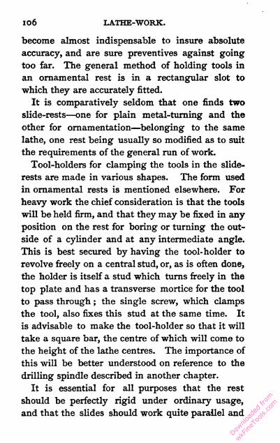
106 LATHE-WORK.
become almost indispensable to insure absolute
accuracy, and are sure preventives against going
too far. The general method of holding tools in
an ornamental rest is in a rectangular slot to
which they are accurately fitted.
It is comparatively seldom that one finds two
slide-rests—one for plain metal-turning and the
other for ornamentation—belonging to the same
lathe, one rest being usually so modified as to suit
the requirements of the general run of work.
Tool-holders for clamping the tools in the slide-
rests are made in various shapes. The form used
in ornamental rests is mentioned elsewhere. For
heavy work the chief consideration is that the tools
will be held firm, and that they may be fixed in any
position on the rest for boring or turning the out
side of a cylinder and at any intermediate angle.
This is best secured by having the tool- holder to
revolve freely on a central stud, or, as is often done,
the holder is itself a stud which turns freely in the
top plate and has a transverse mortice for the tool
to pass through ; the single screw, which clamps
the tool, also fixes this stud at the same time. It
is advisable to make the tool-holder so that it will
take a square bar, the centre of which will come to
the height of the lathe centres. The importance of
this will be better understood on reference to the
drilling spindle described in another chapter.
It is essential for all purposes that the rest
should be perfectly rigid under ordinary usage,
and that the slides should work quite parallel and
Downlo
aded
from
wkFine
Tools
.com
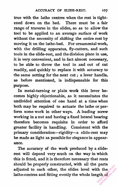
ACCURACY OF SLIDE-REST. 107
true with the lathe centres when the rest is tight
ened down on the bed. There must be a fair
range of traverse in the slides, so as to allow the
tool to be applied to an average surface of work
without the necessity of shifting the entire rest by
moving it on the lathe-bed. For ornamental work,
with the drilling apparatus, fly-cutters, and such
tools in the slide-rest, and the division plate in use,
it is very convenient, and in fact almost necessary,
to be able to throw the tool in and out of cut
readily, and quickly to replace it with accuracy to
the same setting for the next cut ; a lever handle,
as before mentioned, is indispensable for this
purpose.
In metal-turning or plain work this lever be
comes highly objectionable, as it necessitates the
undivided attention of one hand at a time when
both may be required to actuate the lathe or per
form some work in other ways. A leading screw
working in a nut and having a fixed lateral bearing
therefore becomes requisite in order to afford
greater facility in handling. Consistent with the
primary consideration—rigidity—a slide- rest may
be made as light as possible for elegance in appear
ance.
The accuracy of the work produced by a slide-
rest will depend very much on the way in which
this is fitted, and it is therefore necessary that rests
should be properly constructed, with all the parts
adjusted to each other, the slides level with the
lathe-centres and fitting evenly the whole length of
Downlo
aded
from
wkFine
Tools
.com

108 LATHE-WORK.
their travel without shake ; the strength of the
parts being so proportioned that the whole struc
ture will be quite rigid.
In a self-acting screw-cutting lathe the slide-rest
is fitted to slide on the bed itself, and is moved
along by the leading screw of the lathe usually
extending the whole length of the bed, the nut in
which this engages being split and actuated by a
cam under the control of the turner, who can
disengage the nut from the screw at any time in
stantaneously, and so arrest the motion of the rest
along the bed without stopping the lathe. Such a
rest fitting on a dovetail slide cannot be removed
from the bed entirely, but may be slid to any con
venient place along its length.
The screws used to actuate the slides are called
leading screws ; there is no rule as to their size and
pitch, and right and left-handed threads are equally
effective ; so also square and angular threads may be
used indifferently. For coarse pitches of small dia
meter, square threads make a stronger screw than
angular ones. For rate of thread a good propor
tion is ten to the inch for a 5-inch lathe. Relative
to the adoption of right and left-handed screws
there seems to be much diversity of opinion, and
makers do not seem to agree on the subject. Some
put both screws right-handed, some, though less
often, put left-handed, and some, amongst whom
are numbered the best, put one left and one right-
handed leading screw to the slide-rest. The only
object in having them this last way is to afford the
Downlo
aded
from
wkFine
Tools
.com

RIGHT AND LEFT SCREWS. 109
operator the convenience of producing similar
results by similar motions of the handles.
By standing at a slide-rest and making the
experiment, it will be found that on turning the
two handles in the same direction the motion is
really in opposite directions. Supposing both
handles of the slide-rests to be in their highest
position, on pushing from you the one which is
parallel the screw is turned towards the right ;
when the other handle at right angles to the bed
is pushed away the screw is turned towards the
left, so that in turning the two handles away from
you they really turn in opposite directions.
Therefore, in order to make the same apparent
motion produce the same actual effect, a left-handed
screw is put in for the top slide, while a right-
handed one is used for the bottom one ; and though
no absolute advantage is gained, yet it is very con
venient. In all cases the back centre should be
actuated by a screw of the same rake as the one in
the top slide, so that motion of the handles in the
same direction will produce like results. When
the top of the slide-rest and the poppit barrel are
actuated by reverse screws, the effect is very em
barrassing, so that these two screws had best
correspond, whether they be right or left.
The nuts for leading screws may be of wrought
iron, brass, gun metal, or almost anything similar ;
gun metal works more smoothly, and if attention is
paid to lubrication will last as long as required.
The nuts need not be screwed on to the under
Downlo
aded
from
wkFine
Tools
.com

HO LATHE-WORK.
sides of the saddles ; .they may be just let into a
hole drilled for the purpose, a round tail being
turned on each nut to fit. The lateral motion of
the leading screws has to be prevented ; they are
usually fitted with bearings in the respective slide
castings, and to stop endway movement of the
screws when actuating the saddles several methods
are made use of, each having its special claims.
One good plan is to reduce the diameter of the
end of the screw for a length just exceeding the
thickness of the casting, and fit this part in the
hole, allowing it to project say the eighth of an
inch ; a steel washer has to be fitted on to the pro
jecting part so that it cannot turn round indepen
dently of the screw. A small hole is drilled up the
centre of the screw end ; this hole is tapped, and a
screw fitted with a large head, sufficient to take a
good bearing against the washer, and so keep it in
its place, that is, firm against the casting. When
a plate is put on, as described lower down, to take
the thrust of the screw, the boss cannot well be
used as a divided head, which is often very desir
able, and this is why a nut on the rear end of the
screw is preferable. In another plan a boss is left
at the handle end of the screw ; this bears against
the casting, and at the other end a nut is screwed
with a washer fitted on hexagonally, and both are
let into a countersunk hole in the casting, prevent
ing the screw from being withdrawn. The boss on
the screw may be made to go into a countersink
with its thrust bearing against a small plate held
Downlo
aded
from
wkFine
Tools
.com

SLIDE-REST SCREWS. Ill
on by two screws ; the other end of the leading
screw is turned down to form a pivot the size of the
diameter of the bottom of the thread, and fits into
the hole in the casting.
Conical bearings are sometimes made to the
screw, but the wear is so very slight that there is
no need for this. Providing the screw is carefully
and well fitted in the first instance, it will last out
the other parts of the rest, and therefore conical
bearings may be considered useless. The motion
of the screw without moving the saddle, caused by
slackness in the fittings of the screw in its bearings
and in the nut, called back lash, does not detract
from the slide-rest's utility when applied to its
legitimate purpose, though this back lash is often
a source of much trouble and annoyance. But it
cannot possibly be eliminated entirely without the
use of double screws, or some such costly contri
vance.
For turning cones, the upper slide of the com
pound slide-rest turns so that it may be placed at
an angle with the bed, some rests being arranged
so that the top side may swivel all round, and
others have only a small angular motion, which is,
however, in most cases, sufficient, as cones are not
generally required very obtuse. The ways in which
the angular motion of the side is obtained are
these :—The best plan, which allows the top slide to
be swung round all the way from right angles to
parallel with the bottom side, is managed by
turning a T-shaped groove in the thickness of the
Downlo
aded
from
wkFine
Tools
.com

1 1 2 LATHE-WORK.
saddle of the bottom slide into which the heads of
the two bolts fit, and consequently the top slide
may swivel round entirely. The more general plan
is to screw the bolts into a hole in the under saddle,
and cut a circular slot on each side of the circular
base plate of the upper slide, extending as far as
the sides of the slide will allow, and in this case
the length of the curvilinear slots determines the
amount of the angular motion of the top slide.
The first-mentioned plan is, of course, the better,
but it involves more work, and turning the T-groove
requires a great deal more care to ensure the depth
being equal on both sides so that the heads of the
bolts will take a fair bearing. It is seldom required
to set over the top slide more than 300 for ordinary
work, and the second plan of slots allows this.
Being easier of construction it is consequently the
more generally adopted. The top slide swivels on
a steel pin, driven tightly into a hole in one casting
(it is immaterial which), the other casting having a
hole carefully fitted to the projecting piece of the
pin, which forms a pivot at the centre of motion.
The fitting of this pin must be accurate, without
shake, otherwise no dependence can be placed on
the angular setting as shown by the index which
is fitted up, as described further on, to show the
angle at which the rest is set.
The best height for the top plate of the rest, on
which the turning tools fix, will depend on the size
of steel generally employed for these tools; the
usual size of steel should lie wholly beneath the
Downlo
aded
from
wkFine
Tools
.com
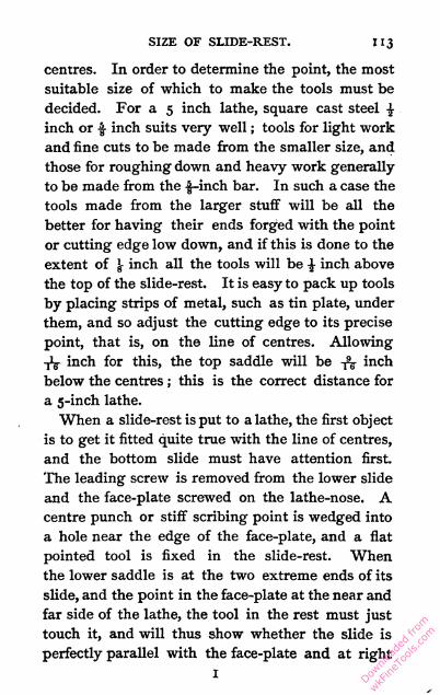
SIZE OF SLIDE-REST. 1 13
centres. In order to determine the point, the most
suitable size of which to make the tools must be
decided. For a 5 inch lathe, square cast steel $
inch or $ inch suits very well ; tools for light work
and fine cuts to be made from the smaller size, and
those for roughing down and heavy work generally
to be made from the -jj-inch bar. In such a case the
tools made from the larger stuff will be all the
better for having their ends forged with the point
or cutting edge low down, and if this is done to the
extent of } inch all the tools will be £ inch above
the top of the slide-rest. It is easy to pack up tools
by placing strips of metal, such as tin plate, under
them, and so adjust the cutting edge to its precise
point, that is, on the line of centres. Allowing
-jig- inch for this, the top saddle will be -^ inch
below the centres ; this is the correct distance for
a 5-inch lathe.
When a slide-rest is put to a lathe, the first object
is to get it fitted quite true with the line of centres,
and the bottom slide must have attention first.
The leading screw is removed from the lower slide
and the face-plate screwed on the lathe-nose. A
centre punch or stiff scribing point is wedged into
a hole near the edge of the face-plate, and a flat
pointed tool is fixed in the slide-rest. When
the lower saddle is at the two extreme ends of its
slide, and the point in the face-plate at the near and
far side of the lathe, the tool in the rest must just
touch it, and will thus show whether the slide is
perfectly parallel with the face-plate and at right
Downlo
aded
from
wkFine
Tools
.com

114 LATHE-WORK.
angles with the bed. Should the slide be at an
angle, the contact of the points will at once show
it, and the bottom of the rest must be filed to bring
it right. The lower slide finished, the upper one is
next treated in a similar manner, using a bar
between the centres with a projecting point in it
instead of the face-plate.
When the two slides are adjusted to the exact
position for turning parallel and flat respectively, a
legible mark should be made to enable the top
slide to be reset at precisely the same angle after
it has been shifted for conical turning. A scale
and index point to show the angular motion of the
slide are sometimes put, and will be found very
convenient. The divisions should always represent
degrees, that is, the 360th part of a circle, or parts
of degrees. Then cones tapering to the amount
required can be turned by setting over the slide-
rest to the necessary distance, and there will be no
need for callipering. The advantages of an index
will best be appreciated when it is required to turn
a cone and a hole for it to fit in. The large end of
the cone will nearly always be towards the mandrel
end, and the hole will be reversed, that is, with
its largest end away from the mandrel. Con
sequently the slide-rest will have to be set at
reversed angles to turn the hole and the plug ;
without a scale it will be most difficult to set the
rest at angles which correspond precisely. In
making such an index the divisions are usually
marked upon the saddle of the slide, and the point
Downlo
aded
from
wkFine
Tools
.com

SPHERICAL RESTS. 115
is fixed by a couple of screws to the circular base
plate of the top slide. This point may be itself
fixed to read correctly for turning parallel with
the index at oc. The best plan for ease in reading
is to make the index with a flat end about -J- inch
wide, with a line marked in the centre to read
against the scale lines, as it is much easier to dis
tinguish the continuity of a line than the position
of a pointer with respect to a line.
Spherical slide-rests are sometimes used for pro
ducing, but chiefly for ornamenting spherical sur
faces ; they are seldom met with except on orna
mental lathes of the highest class used by amateur
turners. The circular motion is produced by fitting
a worm wheel and tangent screw to the base of the
slide, which is then turned round by means of a
handle in precisely the same direction as it would be
for conical turning. There are many other additions
necessary for the proper use of a spherical slide-
rest, and owing to its complicated construction
further details would be of little use unless an
elaborate description was given, and that would
not be within the scope of the present treatise.
The slide-rest is the receptacle for various kinds
of apparatus used for wheel-cutting and for shaping
material which is held by the mandrel; some of these
are described in other chapters. The tools proper
consist of square bars of steel having one and
sometimes both ends formed into cutters ; these
solid tools are used for roughing down work and
the general run of turning. For special cutters
Downlo
aded
from
wkFine
Tools
.com

Il6 LATHE-WORK.
shaped for particular purposes, or those used in
certain ways, tools called slide-rest cutter-bars are
used. These are bars similar to the ordinary tools
with ends shaped to hold small cutters, which may
be made with much less trouble than the solid
tools mentioned above.
A slide-rest should be strong enough at all parts
not merely to resist absolute breakage but to main
tain perfect rigidity under the wear and tear of a
heavy cut. Several items have to be taken into
consideration when judging the strength, or rather
inflexibility, of a rest. A certain amount of metal
is requisite to make a solid tool, but much more
depends on the way in which it is fashioned than
appears to be generally understood, judging from
the clumsy designs which are sometimes made.
Good fitting is also essential to the main object
in view. A carefully fitted slide-rest, of neat and
elegant design, will stand more hard wear and tear
than half-a-dozen of some of the clumsy, heavy,
badly-proportioned tools thrown in the market by
second-rate manufacturers.
Downlo
aded
from
wkFine
Tools
.com

CHAPTER X.
SLIDE-REST TOOLS.
Angles suited for various materials—Useful tools for general purposes
—Cranked tools, knife tools, parting tools, spring tools—Tools
for inside turning—Correct height and adjustment necessary.
SoDE-rest tools are of numerous forms, some the
result of peculiar individual fancy, others made
to meet the exigencies of the work they have to
perform. In the chapter treating of cutter-bars
much information applicable to solid tools will be
found, and these latter it will be seen, by what is
there stated, are to a large extent superseded by
cutter-bars from motives of economy. The solid
tools are, however, very much used, and in small
workshops they generally do the whole of the
work, cutter-bars being probably not introduced
from a notion that their prime cost would not be
warranted by the work that would be exacted from
them, or that the economy would not be commen
surate with the cost. Solid tools are usually made
of square steel, though that of varying rectan
gular section is sometimes used, without any ap
parent object, however, unless in the case of tools
of particularly broad or narrow width. Cast steel
Downlo
aded
from
wkFine
Tools
.com

Il8 LATHE-WORK.
of special quality should be always used, as the
ordinary material is not adapted to stand the work
required of a slide-rest tool.
The size of the steel used will be determined
according to the height of the slide-rest plate, as
explained on page 113; the length used is optional,
so long as it is sufficient to leave enough shank to
be clamped under the tool-holder. Some tools are
made with each end formed into a cutter, and thus
the number of available cutting edges is doubled
without increasing the number of tools. This
plan is one that finds little favour, though in some
forms of tool nothing can be said against it. For
example, screw tools for the slide-rest are 'always
made with the comb at both ends, they also being
usable either side up. Tools that are cranked, if
made double ended, must have the cranks at right
angles or on opposite sides, as otherwise the tool
cannot be laid flat on the top of the slide-rest.
The angles best suited for the particular material
to be operated upon are most desirable in slide-
rest tools, and after having had some experience
with hand tools, more especially as applied to
soft-wood turning, anent which some information
is given in another chapter, the advantage . of
various angles will be appreciated. It will be
understood that the cutting edge will penetrate
best when it is thinnest ; other considerations,
however, prevent the adoption of this rule unre
servedly ; and for metal work tools are found to
act best when the faces form the cutting edge at an
Downlo
aded
from
wkFine
Tools
.com

ANGLES FOR CUTTING EDGES. 119
angle of from 6o° to 900. The face of the tool
coming next to the work requires to be ground at
a slight angle, leaving the point prominent to pre
vent the whole face touching the work, and so by
the friction greatly increasing the labour of turning.
When this requirement is satisfied the face should
be as straight as possible, and 30 from the perpen
dicular suffices. ' This applies equally to tools with
acute edges used on wood, though when we come
Fig. 22.—Angles of Turning Tools for Wood and Metal.
to knife edges the face of the tool itself usually
rests against the work it has to cut and there
is no angle of clearance.
Fig. 22 herewith shows tools correctly applied
for cutting both wood and steel. By this it is
seen that the slide-rest tool, with a strong cutting
edge suited to dividing the cohesive metal, and the
acute wood-turning chisel, each have the lower
face angle placed in the same position with regard
to the work. Therefore it is only the upper face
Downlo
aded
from
wkFine
Tools
.com
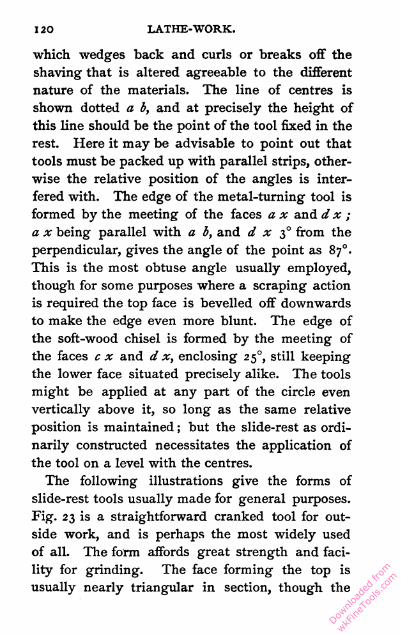
120 LATHE-WORK.
which wedges back and curls or breaks off the
shaving that is altered agreeable to the different
nature of the materials. The line of centres is
shown dotted a b, and at precisely the height of
this line should be the point of the tool fixed in the
rest. Here it may be advisable to point out that
tools must be packed up with parallel strips, other
wise the relative position of the angles is inter
fered with. The edge of the metal-turning tool is
formed by the meeting of the faces a x and d x ;
a x being parallel with a b, and d x 30 from the
perpendicular, gives the angle of the point as 870.
This is the most obtuse angle usually employed,
though for some purposes where a scraping action
is required the top face is bevelled off downwards
to make the edge even more blunt. The edge of
the soft-wood chisel is formed by the meeting of
the faces c x and d x, enclosing 250, still keeping
the lower face situated precisely alike. The tools
might be applied at any part of the circle even
vertically above it, so long as the same relative
position is maintained ; but the slide-rest as ordi
narily constructed necessitates the application of
the tool on a level with the centres.
The following illustrations give the forms of
slide-rest tools usually made for general purposes.
Fig. 23 is a straightforward cranked tool for out
side work, and is perhaps the most widely used
of all. The form affords great strength and faci
lity for grinding. The face forming the top is
usually nearly triangular in section, though the
Downlo
aded
from
wkFine
Tools
.com
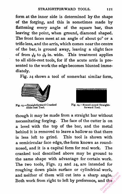
STRAIGHTFORWARD TOOLS. 121
form at the inner side is determined by the shape
of the forging, and this is sometimes made by
flattening every angle of the square bar, thus
leaving the point, when ground, diamond shaped.
The front faces meet at an angle of about 900 or a
trifle less, and the arris, which comes near the centre
of the bar, is ground away, leaving a slight face
of from -jV to -jJg- in. wide. This treatment applies
to all slide-rest tools, for if the acute arris is pre
sented to the work the edge becomes blunted imme
diately.
Fig. 24 shows a tool of somewhat similar form,
Fig. 23.—Straightforward Cranked Fig. 24.—Round-nosed Straight-
Slide-rest Tool. forward Tool.
though it may be made from a straight bar without
necessitating forging. The face of the cutter is on
a level with the top of the bar, and the metal
behind it is removed to leave a hollow so that there
is less left to grind. This tool is shown with
a semicircular face edge, the form known as round-
nosed, and it is a capital form for real work. The
cranked tool described above may be ground to
the same shape with advantage for certain work.
The two tools, Figs. 23 and 24, are intended for
roughing down plain surface or cylindrical work,
and neither of them will cut into a sharp angle.
Both work from right to left by preference, and the
Downlo
aded
from
wkFine
Tools
.com

122 LATHE-WORK.
top face is ground to a slight slope, to leave the
left or leading edge a trifle higher. Both may
be used in the reverse direction, though in that
case the grinding ought to be done accordingly.
When such tools are employed indiscriminately in
either direction the top surface is ground off square,
always, of course, sloping backwards to leave the
extreme point highest, and this in accordance with
the material to which it is applied.
A left-handed cranked tool is shown next, in
Fig. 25. This is very much like Fig. 23, with the
point bent sideways, towards the left, so that it is
brought beyond the level of the
side of the tool shank ; by this
means the tool is available for use
Fig. 25— Left -handed *n the extreme corner of an angle
Cranked ;Slide - rest i -i . j . . _r
Tool. where a cylinder joins a surface.
For example, in turning a bolt
the front corner would be brought to work on the
cylindrical part and the left corner would surface
the head. The angle of this point is always less
than a right angle, otherwise there would be no
clearance and the whole breadth of the edge would
be against the work, causing much unnecessary
friction ; an angle embracing about 80° will be found
right. A corresponding tool bent to the opposite
side, and called a right-handed cranked tool, is
required for working in the reverse direction. Its
form is precisely similar, so that no illustration is
required ; the point is to the right, as Fig. 25 is to
the left.
Downlo
aded
from
wkFine
Tools
.com

PARTING TOOLS. 1 23
Fig. 26 is a knife-edge side tool used for turning
the end surface of a cylinder running between the
centres, the form of this tool allowing it to go right
up to the point of the poppit head, which the tools
hitherto described are not adapted for. It will be
seen that the end of the tool is forged to a narrow
blade, and this is ground flat on its face side—that
is the one represented as the furthest away in the
illustration—but at an angle to clear, and the top
and end are bevelled off to form cutting edges. A
corresponding reversed tool for cutting on the left-
hand surface of work is sometimes made, but it
Fig- 26.—Knife-edge Side Tool Fig. 27.—Slide-rest Parting
for Slide-rest. Tool for Metal.
will be readily understood that its use is of most
rare occurrence for work on the lathe, though for
planing of course both side tools are equally in
requisition.
A parting tool for metal is shown in Fig. 27 ;
in this the tool is forged with a thin central blade,
as shown in the figure, and sometimes, when the
width is very slight, it has a much greater depth,
occasionally as much as an inch to give the centre
tool support. The length of the blade should be
somewhat proportionate to the work it has to do,
and it would be absurd to use a blade long enough
to part 3-inch stuff for that under an inch in
Downlo
aded
from
wkFine
Tools
.com

1 2 4 LATHE-WORK.
diameter. The tool is ground on both sides,
tapering slightly to leave the top edge widest, and
the blade must stand accurately upright to be
clear of the sides of the groove that it cuts. The
front end should be slightly the widest, so that the
tool will not rub on its side edges as it proceeds
through the work; if quite parallel it will act.
Perfect straightness of the blade and its parallelism
with the slide by which it is actuated in its forward
path are essential. In short, the parting tool, when
at work, must cut only with its narrow front edge,
which is ground off square; its width may be
from -nr to i inch, according to the size. Some
further information on parting tools is given in the
chapter on cutter-bars.
The next illustration shows another tool some
what out of the usual form ; it is called a spring
tool, and its object is to present an edge that will to
an extent give and take with the irregularities of
the work, a property which, despite of all that may
be said to the contrary, is a most undesirable one
if the object of turning is to produce true cylinders.
The form at Fig. 28 places the point of flexure
much above the line of centres, and thus when any
undue pressure is brought to bear on the edge of
the tool it springs from the work, that is, if applied
at the exact height of the centres. With a keen
edge carefully whetted on an oilstone and a blunt
angle, this tool forms a good planisher for long
brass rods, but for the most part finishing is done
with emery paper on a file. A piece of wood
Downlo
aded
from
wkFine
Tools
.com

imiSide tools. 125
wedged under the spring part will very materially
strengthen the tool if less spring is wanted for a
special job.
Inside turning with slide-rest tools often takes
the place of boring, and vice versa, according to the
ease with which the work to be operated upon may
be mounted on the lathe. The tools used in the
slide-rest for this purpose are very similar in their
form, and Fig. 29 may be taken as a representative
type. The dimensions are varied to suit the size
of the hole in which the tool has to go, the size of
the tool being generally restricted by that of the
Fig. 28.—Spring Turning Tool for Slide- Fig. 29.—Inside Turning
rest. Tool for Slide-rest.
hole. Referring to the illustration, it will be seen
that the shank part is made cylindrical, the length
being in accordance with the depth for which the
tool is available, short tools being the most rigid,
whilst deep holes necessitate the use of long tools.
The cutting edge is formed by forging a lip to
wards the left side of the shank, and this is ground
to the form shown, the top face being as nearly as
possible on a level with the diametrical centre of the
shank. Thus the tool can be introduced into the
smallest hole allowable from its size, to cut at the
correct height—i.e. at the line of centres. The tool
shown is intended to cut inwards only, and round
Downlo
aded
from
wkFine
Tools
.com

1 26 LATHE-WORK.
nosed edges formed like Fig. 24 are useful for
cutting forwards and backwards through a
thoroughfare hole, but are objectionable for holes
that should have a flat bottom, from the circum
stances explained in the comments on outside tools
of the same form. With careful usage an inside
tool may be employed of such slight dimensions
that it will bore through a 5-inch hole 2 inches
deep, and when the depth is not so great the
diameter may be diminished to even less. The
cylindrical part of the shaft of inside tools should
be straight and level, though a slight taper is often
no detriment and strengthens the tool materially.
The projecting lip must be comparatively short, for
all small tools or the leverage it affords will impair
the cutting and spoil the truth of the boring even
if it does not cause a breakage.
As has been shown, it is necessary to apply the
tool to the work at a correct height, or else, no
matter how good and well made it may be, the tool
will fail to perform properly and to the best advan
tage. A gauge should be made, to be used every
time a tool is fixed in the slide-rest, to test the
height of its cutting point. A plain cylinder or
piece of tube with the ends made perfectly flat, so
that it will stand, and of such a length that when
stood on a particular plane of the slide-rest, or on
the lathe-bed itself, its upper surface is exactly
level with the line of centres, is all that is neces
sary; and when the tool is finally clamped the
height of its edge should be gauged. The height
Downlo
aded
from
wkFine
Tools
.com

GAUGE FOR HEIGHT. 127
is of course adjusted by means of strips of metal ;
thin bar iron and strips of tin of various thick
nesses are best for this purpose, and the gauge is
placed in position to afford a guide during this
process. The correct adjustment cannot be too
strongly urged, and a proper gauge is indispen
sable. If a tool does not work properly at the
correct height, it is sure evidence that it is badly
formed ; and though a tool may be made to work
apparently better above or below the centres,
yet in such a position it is at a disadvantage, and
should be put right according to the principles
explained in this chapter.
Downlo
aded
from
wkFine
Tools
.com

CHAPTER XI.
SLIDE-REST CUTTER-BARS-
Advantages over solid tools—Some of those of most general applica
tion described—The graver used in the slide-rest—Straightforward
tool, parting tool, internal tool—Saving effected by the use of
cutter-bars.
Ix many respects there are advantages in the use
of cutter-bars as slide-rest tools in place of the
usual form of solid bar steel, in which but a very-
small fraction of the metal is of any direct use so
far as the cutter proper is concerned. The shank
of the tool consists of solid metal of the same
quality as is the point and cutting edges, and that
is invariably the best, and consequently a costly
kind. In cutter-bars one shank is used for any
number of cutters, just as is the case with boring-
bars, and thus only a small piece of metal has to
be wrought, hardened, tempered, and ground when
a cutter is required. A 6-inch bar of f-inch square
steel, weighing over half a pound, is replaced by an
inch length of J-inch square bar, weighing a quarter
of an ounce. In making a dozen of such cutters the
saving in metal, which would be a matter of using
a quarter of a pound instead of 8 pounds, is only an
Downlo
aded
from
wkFine
Tools
.com

CUTTER-BARS. I2Q
example of the saving in labour of making, and in
the space the finished tools will occupy. As there
are no direct advantages in the use of the more
expensive tools, the use of cutter-bars has con
siderably increased. The saving effected by their
use in large factories is enormous.
A cutter-bar must be essentially able to hold the
cutter perfectly rigid, and so make it, for practical
purposes, solid with the bar. In some badly con
trived tools this, the chief desideratum, is neglected,
and consequently such bars, being of little or no
use, are discarded, and gain for cutter-bars, taken
as a class, a bad reputation. That the cutters can
be removed and replaced with ease and rapidity is,
for convenience in use, an important feature, and
to this is sometimes sacrificed the firm grip so
essential. To the mechanic whose theoretical edu
cation has kept pace with his practical experience
the arrangement of a thorough firm hold combined
with a readily released grip will be easy. The
wedge offers a ready and familiar example, and
when this contrivance is constructed to be with
drawn easily it is, perhaps, the best of all clamping
arrangements, but it requires solid points on which
to take its bearings.
Clamping-screws are very good, and if there is
sufficient material for a proper allowance of thread,
both in respect to diameter and length, then a
screw holds firm enough for all things. In cutter-
bars, however, the proper size of these parts has
usually to be reduced very much, and in many cases
K Downlo
aded
from
wkFine
Tools
.com

13O LATHE-WORK.
the projecting head of a screw is objectionable, if
not absolutely forbidden. Screws applied to draw
parts together and hold the cutters in a vice-like
grip are effective, and when allowable may be used
with most satisfactory results. There are many
ways in which cutters may be held, but they need
not be discussed here ; those named will suffice for
the bars of which descriptions are to be given.
The examples are offered as types on which it is
quite possible to effect alterations and modifica
tions to suit special requirements. The illustra
tions may serve as working drawings to those
desirous of constructing
facsimile tools.
The ordinary graver
Fig. 30. — Slide-rest Cutter-bar, for USed for hand turning
holding Gravers.
may be fixed in the slide-
rest by means of the holder shown in Fig. 30, which
givesa sectional and topviewof the arrangement. In
this case the cutter-bar consists of two strips ofmetal
with an angular groove running lengthwise, into
which the graver fits. The sides of this groove are
inclined so as to bring the tool to the best position
for cutting, which may be best seen in the sectional
view. The angles are 6o° and 30° respectively,
making together a right angle fitting the square
tool. The two halves of the bar do not quite come
into contact ; they, however, take a fair bearing on
the tool, and are so kept sufficiently rigid for all
practical purposes. In making a bar of this de
scription a piece of metal of double the intended
Downlo
aded
from
wkFine
Tools
.com
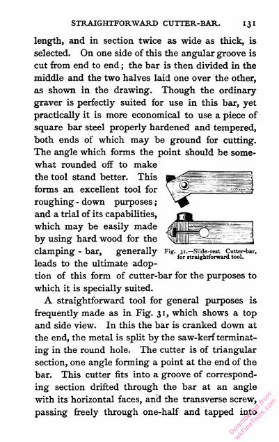
STRAIGHTFORWARD CUTTER-BAR. 131
length, and in section twice as wide as thick, is
selected. On one side of this the angular groove is
cut from end to end ; the bar is then divided in the
middle and the two halves laid one over the other,
as shown in the drawing. Though the ordinary-
graver is perfectly suited for use in this bar, yet
practically it is more economical to use a piece of
square bar steel properly hardened and tempered,
both ends of which may be ground for cutting.
The angle which forms the point should be some
what rounded off to make
the tool stand better. This
forms an excellent tool for
roughing - down purposes ;
and a trial of its capabilities,
which may be easily made
by using hard wood for the
clamping - bar, generally *'ig. 31.—snde-rest cutter-bar,
for straightforward tool.
leads to the ultimate adop
tion of this form of cutter-bar for the purposes to
which it is specially suited.
A straightforward tool for general purposes is
frequently made as in Fig. 31, which shows a top
and side view. In this the bar is cranked down at
the end, the metal is split by the saw-kerfterminat
ing in the round hole. The cutter is of triangular
section, one angle forming a point at the end of the
bar. This cutter fits into a groove of correspond
ing section drifted through the bar at an angle
with its horizontal faces, and the transverse screw,
passing freely through one-half and tapped into
Downlo
aded
from
wkFine
Tools
.com
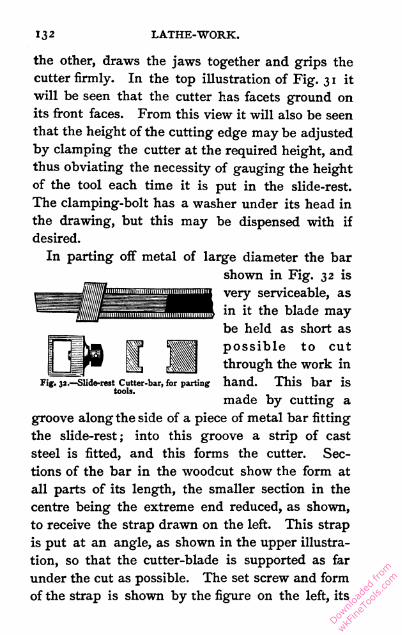
132 LATHE-WORK.
the other, draws the jaws together and grips the
cutter firmly. In the top illustration of Fig. 31 it
will be seen that the cutter has facets ground on
its front faces. From this view it will also be seen
that the height of the cutting edge may be adjusted
by clamping the cutter at the required height, and
thus obviating the necessity of gauging the height
of the tool each time it is put in the slide-rest.
The clamping-bolt has a washer under its head in
the drawing, but this may be dispensed with if
desired.
In parting off metal of large diameter the bar
shown in Fig. 32 is
very serviceable, as
in it the blade may
be held as short as
possible to cut
through the work in
hand. This bar is
made by cutting a
groove along the side of a piece of metal bar fitting
the slide-rest ; into this groove a strip of cast
steel is fitted, and this forms the cutter. Sec
tions of the bar in the woodcut show the form at
all parts of its length, the smaller section in the
centre being the extreme end reduced, as shown,
to receive the strap drawn on the left. This strap
is put at an angle, as shown in the upper illustra
tion, so that the cutter-blade is supported as far
under the cut as possible. The set screw and form
of the strap is shown by the figure on the left, its
Fig. 32.—Slide-rest Cutter-bar, for parting
tools.
Downlo
aded
from
wkFine
Tools
.com

PARTING-TOOL CUTTER-BAR. 1 33
extreme left representing the edge, of which the
face is seen in the top figure. In this cutter-bar
the blades used may be of different thicknesses,
according to the work to which they are applied ;
the width should always fit the groove accurately.
The blades are ground to taper from top to bottom,
so as to leave the cutting edge, that is the top,
wide enough to cut a channel, in which the lower
part is free. The groove in the bar is at a slight
angle to keep the blade upright, and to give it a fair
bearing ; the strap is also shaped slightly angular
at that part where the blade comes. It will be
readily seen that the blade is drawn out to any
desired extent, and there fixed by the set screw in
the strap, and thus the length is regulated accord
ing to the depth that has to be cut. The blade
itself may be tempered far more precisely than if
part of a solid tool ; and, moreover, the cutting
edge may be left much harder than usual by tem
pering from the lower edge, which by being
softened lends toughness and support to the hard
cutting edge.
It may not be inappropriate here to point out
that when a metal bar is severed by means of a
parting tool in the lathe, the channel cut invariably
terminates in a square fiat bottom, and those who
have had experience will know that in such con
dition the metal is comparatively difficult to break.
If the channel ends in an acute angle the metal
separates much easier. With this object one end
of the blade may be ground to an acute point and
Downlo
aded
from
wkFine
Tools
.com

134 LATHE-WORK.
used to make the final cut before breaking, and so
save much labour. Sharpness of the point is most
important to ensure an easy break.
For internal work, when the hole being operated
upon is of small size, the bar shown in Fig. 33
takes the place of a solid tool of similar outline.
In that the small piece forged up from the solid
to form the cutting-point soon gets ground away in
the sharpening process, and the tool has to go
through the fire again to be made serviceable. In
the cutter-bar illustrated the bar has a portion of
its length turned cylindrical to a size suited to the
Fig. 33-—Slide-rest Cutter-bar, for inside turning.
usual requirements of such a tool. Into the end
of this cylindrical part, starting from the diamet
rical edge, and at an angle of 450, a hole is drilled,
as shown by the dotted outline in the lower figure ;
this hole is made tapering and a flat facet filed on
the bar at its mouth. Small pieces of cylindrical and
tapering steel are fitted to it, and the ends of these
are fashioned into cutters, as shown in Fig. 33, where
three distinct views are given. The hole is some
times made square by drifting and filing and the
cutters of a corresponding section, but a properly
fitted round cone is easier to make and answers
Downlo
aded
from
wkFine
Tools
.com

ADVANTAGES OF CUTTER-BARS. 1 35
the purpose equally well. In grinding these cut
ters it is preferable to hold them in a tool made by
drilling a conical hole in a bar, from which they
project more than when in the cutter-bar itself;
the grinding may then be done with greater ease
and certainty. When a cutter is worn too short
for use it is cast on one side, and a new one that
costs but an inconsiderable fraction for material,
and that may be made in a few minutes, is put in
place of it.
Speaking generally of the four cutter-bars de
scribed, it is scarcely necessary to point out the
great saving of material effected by their use ; that
is to say, the small cost at which the worn-out tool
can be rendered as new, as compared with a similar
process on the solid tool. Apart from this, each
form of bar has peculiar advantages over the solid
tool that it is intended to replace. Fig. 32 is,
perhaps, the most obvious instance of this, but each
has an advantage. Again, by making numerous
cutters to these bars they are rendered equivalent
to an equal number of solid tools, that is, pro
viding only one is to be used at a time, at a very
small fraction of the cost. For example, three
blades fitted to the parting-tool, Fig. 32—a wide,
a medium, and a narrow one—would make that
tool equal in its range to three solid tools of cor
responding dimensions. Small cutters of various
forms adapted to particular purposes, fitted to the
inside tool, Fig. 33, take the place of complete solid
bars. The value of material and workmanship of
Downlo
aded
from
wkFine
Tools
.com
136 LATHE-WORK.
each of these would suffice for, perhaps, twenty
small cutters, each of which would be equally
efficacious. A direct saving in the cost of material
is made by using iron for the bars in place of
steel for the solid tools. In most cases good iron
answers all the purposes of a cutter-bar, though
occasionally it is better to use steel ; that is, in
cases where the material has to be reduced to small
dimensions, as it would be in Fig. 33 if made to go
into a hole J inch in diameter.
Downlo
aded
from
wkFine
Tools
.com
CHAPTER XII.
OVERHEAD GEARING.
Fixed and portable—Single bands and compound gearing—Fixed bars
—Swinging bars —Revolving shafting—Screw-cutting by band-
gearing—Shape of grooves for the bands.
Overhead gear designates the apparatus rigged
up to drive drilling spindles, vertical cutters, and
many other appliances of a similar kind. There
are innumerable modifications of gearing used, and
it would be impossible to give anything like an
adequate description even of those commonly
employed, the arrangement adopted depending so
much on purely local facilities and requirements.
Often a wall, ceiling, beam, or other substantial
support is available for the attachment of the gear,
and such a circumstance should be turned to every
possible account. Those lathes which are intended
to be easily movable have the overhead gear, if
any, fitted to standards rising from the frame of the
lathe itself, sometimes cast in one piece with the
standards on which the bed rests, though more
often made separately and bolted to them. Such
supports are somewhat in the way, and their recom
mendation is the fact of their being permanent
Downlo
aded
from
wkFine
Tools
.com

138 LATHE-WORK.
attachments to the lathe and available for use
wherever it may be. Stability necessitates com
paratively bulky castings, which obscure the light
and in other ways impede the workman in various
operations.
Overhead gearing may be divided into two
classes : one in which a single band from the fly
wheel, or other source of motion, is led over pulleys
to the mandrel it has to drive ; the other in which
the band from the source of motion turns a shaft
from which another band, occasionally through
the intervention of other shafts, goes to the object
to be driven. The first method is simple, but
admits of comparatively little variety in, and no
accurate adjustment in the relative velocity of,
the driving and driven pulleys. The second
method is more elaborate, and admits of adjust
ments so fine that screw-cutting, with all the accu
racy of a screw-cutting lathe, can be performed by
its aid. The process of regulating velocities by
means of bands is one that appears to have received
very little attention as applied to extremely accu
rate speeding, but it is a subject well worthy of
investigation.
The first class of overhead gear in its most
simple form consists of a plain bar of rod iron,
fixed paralled to and in a line vertically above the
lathe centres. On the bar are fitted two pairs of
pulleys, one receiving the band from the fly-wheel,
the other leading the band to the cutter. The first
pair of pulleys are usually fixed vertically above the
Downlo
aded
from
wkFine
Tools
.com
SWINGING BAR GEAR. 1 39
driving-wheel, whilst the second are moved along
the bar to suit the position of the apparatus to be
driven. The driving-band having various lengths
to suit is then put in position, and the movable
pulleys are finally fixed at that point where they
keep the band at proper tension for working. If the
band leads fairly on to the apparatus that it is to
drive, or this latter is fitted with proper guide
runners as described in the chapter on the Vertical
Cutter Frame, the gear will work. If, however, the
band leads at too great an angle it will be liable
to slip off, hence the necessity of having various
lengths of band. By judicious arrangement a few
pieces of band suffice for all wants. First cut a
length to fit the shortest workable distance, that is
from the slow motion groove of the fly-wheel to
the drill spindle close to the headstock ; this may
be about 18 to 20 feet. Then cut a length of
6 inches, another of 1 foot, another of 2 feet.
With these three pieces only the band can be in
creased by 6, 12, 18, 24, 30, 36, or 42 inches, giving
a choice of seven lengths as may be found most
convenient, all within only a difference of 6 inches,
which is near enough for almost anything.
Another very simple form is that of a bar jointed
to a standard rising from the lathe-frame near the
headstock. This bar takes two pairs of pulleys as
first described, and the left-hand end has a weight
attached to it to keep the band taut ; this weight is
increased in proportion to the work being per
formed. Fig. 34 illustrates such an apparatus ; the
Downlo
aded
from
wkFine
Tools
.com
140 LATHE-WORK.
vertical bar, shown broken off at its lower end, is of
wrought or cast iron. It has a collar, shown just
under the lower part of the bracket, on which this
rests, or the upper end is shaped pivot-like and the
upper bearing of the bracket is fitted to it. The
bracket itself is of cast iron having bosses bored to
fit the upright loosely so that it turns freely. The
projecting end of the bracket has a lug cast in
with a vertical mortice hole which forms the bear
ing of the rod, a pin shown in the illustration being
Fig. 34.—Swinging Bar overhead Gear.
the axis. The tail end of the bracket has another
upright piece cast with a slot in it, in which the rod
rests when weighted, as shown. This slot also forms
a guide for the bar, when drawn down by the
bands on the pulleys, confining its horizontal
motion which is all made with the vertical bar as
axis, the bracket being quite free to turn round
on this.
The horizontal bar taking the two pairs of
pulleys is shown round at that part where the
pulleys slide. This is an advantage over a square
Downlo
aded
from
wkFine
Tools
.com

SWINGING BAR GEAR. 141
bar in allowing the pulleys to be canted over,
which is sometimes necessary to let the band lead
freely on when running at an angle. That portion
to the left of the first pulleys is flattened to make
it better for the bearing, and the continuation
beyond the vertical slot has holes, two of which
are shown, by which to suspend the weight. When
easily managed it is well to make the suspension
long so as to bring the weight near the ground,
in which position it will be less likely to do
damage in case of a breakdown. The point at
which the bar is centred leaves the right-hand
end heaviest, and it is advisable to put a guard
on it so that it will not fall in the event of the
weight being removed. A piece of wire fastened
round the bracket and rod sufficiently slack to
leave enough motion for working will answer this
purpose, and many other ways will suggest them
selves.
The swinging bar overhead gear is brought into
operation by passing the driving-band round the
lathe fly-wheel, bringing the two ends over the
first pulleys, then over the second and round the
pulley of the apparatus to be driven. The first
pair of pulleys are adjusted to receive and deliver
the band fairly on to the driving-wheel, the second
being adjusted to perform the same functions with
regard to the driller or other cutter which is to be
driven. To assist in this latter adjustment the
arm is swung round to come perpendicularly over
the pulley, and when all is ready to start the bar
Downlo
aded
from
wkFine
Tools
.com

142 LATHE-WORK.
should be tilted downwards, so that the whole of the
weight being on the short arm bears on the band
and keeps it taut. The length of the band should
be so arranged that it will when working leave the
bar nearly in its normal horizontal position, though
of course it must be drawn down sufficiently to lift
the weight quite clear of the bottom of the back
slot in the bracket. It will be obvious that this
form of overhead apparatus has many advantages
over the plain bar first described.
The pulleys used in both the gearings are gene
rally made with the two wheels running side by
side on the same axis. The fork in which they go
being pivoted on to the cannon, which slides on
the bar at right angles to it, allows the pulleys to
move freely and place themselves in line with the
band. It is very necessary for pulleys such as
these to be free to adapt themselves to the direction
in which the band runs, or this will soon be worn
out by cutting against the edges. A plain pulley,
such as may be bought at most ironmongery shops,
if attached to a piece cord of an inch or so in
length, so that it is perfectly free to move in every
direction but one, will answer admirably on the
apparatus just described, and is a very cheap way
of fitting up overhead gear. It is, however, advis
able to knock out the iron pin on which the pulley
revolves, and, after carefully broaching out the
hole, to fit a steel pin to form the axis.
The second form of overhead gear, in which
revolving shafts are used with various bands to
Downlo
aded
from
wkFine
Tools
.com

REVOLVING SHAFT GEAR. 143
transmit the motion, is shown in its most simple
form in Fig. 35. The illustration represents a
lathe, cut through vertically in the plane of the
mandrel pulley. The
bed is shown in section,
surmounted bythehead-
stock which carries the
mandrel and pulley,
from one of the middle
steps of which a band
passes to a stepped pul
ley above. This pulley
is on an axis which re
volves between fixed
centres so that its dis
tance from the lathe
pulley is unalterable.
Moving on the same
centres is a light frame
in which is fitted, to run
perfectly parallel with
the first-named shaft,
another shaft shown in
section on the right-
hand top corner of the
figure. This shaft, being
in a frame only free to
oscillate on the same centres as the shaft driven from
the mandrel, remains constantly at the same dis
tance from it. The second revolving shaft may be
raised or lowered, thereby making considerable
Fig. 35.—Overhead Gear, with Revolving
Shafts.
Downlo
aded
from
wkFine
Tools
.com

144 LATHE-WORK.
alteration in the distance between it and the lathe-
bed, and consequently with any apparatus fixed
in the slide-rest. A grooved pulley fixed on to the
leading screw of the slide running parallel with
the lathe-bed, and actuated by the gearing illus
trated, will traverse at a uniform rate and cut an
accurate screw-thread. Of this more hereafter.
The front shaft of the gear, Fig. 35, is usually
made with a parallel roller extending the whole
length of the lathe-bed likely to be used with
circular cutting apparatus, one end only being
fitted with a stepped cone corresponding with one
on the shaft driven from the mandrel. By means
of this pair of stepped cones, three or four different
rates of speed can be got with the single interme
diary band. The plain cylindrical part will drive
the band going to the cutter-frame at any point of
its length, and thus all distances along the bed
become equally within range. The up and down
motion of the frame is sufficient to make up for any
adjustment necessary through using large or small
pulleys, and hence the one set of bands suffices for
all purposes within the range of the pulleys. The
band driving the main shaft may be led straight
from the lathe fly-wheel.
Though the illustration is only intended to
convey an idea of how the gear is fitted up, still
the practical details can be easily filled in. The
first consideration is to get rigid supports for the
main shaft, on which and about the same centre the
frame oscillates. Hanging standards fixed to the
Downlo
aded
from
wkFine
Tools
.com

SPEED PULLEYS. 1 45
ceiling or an overhead beam are perhaps the best.
The frame is conveniently made of two pieces of
flat bar iron, braced together with stretcher bars
at each end by the holes shown in the illustration,
with a locking nut on both sides, and with centred
screws to form bearings for the pointed ends of the
shafts. To support the front side of the frame and
keep the driving-band taut it must be attached
overhead, and springs of some kind or weights are
very handy to keep up the required tension at all
times. These and other minor details are not
shown, as they are entirely dependent on local
circumstances which it is quite impossible to
anticipate.
Accurate speeding, for screw-cutting purposes,
such as mentioned before, is arranged by using a
particular groove of the mandrel pulley, and making
a pulley for the main shaft of precisely the same
diameter. It is not difficult to turn a wooden pulley
to size so near that the difference is not perceptible
in a thousand revolutions. On the main shaft a
cone pulley of three or four steps is placed exactly
opposite a corresponding one reversed, so that the
same band serves for all speeds alike. Thus three
or four varieties of speed are obtained, and each
must be made accurately proportional. The band
from the front shaft to the grooved disc on the slide-
rest screw must come from an accurately gauged
pulley, and if these two are of equal size, then the
rate of thread cut will depend on the ratio of the
pulleys connecting the two shafts; if these are
L
Downlo
aded
from
wkFine
Tools
.com

1 46 LATHE-WORK.
equal, then the thread cut will be the same rate as
that of the leading screw.
Any number of pulleys may be fitted to the slide-
rest screw, each to suit a special rate which by the
cone pulleys already described will be available for
three or four others, according to the numberofsteps
in the cones. The pulleys for speeding with gut
bands must not have the ordinary V-form of groove,
but a semi-circular one exactly fitting the band.
The band must have hooks and eyes that are of
precisely equal diameter, or each time they pass
over a pulley there will be a jerk in the speed.
Grooves of V-shape jam the band and allow it to
act on a smaller diameter if put on tighter; hence
they cannot be depended on for speeding, even if
once got to size, and this is very hard to accomplish
from the difficulty in determining the diameter for
callipering. Grooves turned with a round nose
tool of the same radius as the band can be calli
pered to a nicety, and their working diameter is
exactly what they calliper plus two semi-dia
meters of the gut band.
Downlo
aded
from
wkFine
Tools
.com

CHAPTER XIII.
DIVIDING APPARATUS.
Its object and use—Dividing the lathe pulley—Numbers most useful
for dividing purposes—Originating and making a division plate—
Drilling the holes—Index pegs of various kinds.
Dividing apparatus is used on the lathe for many
purposes, wheel-cutting being perhaps the most
important, though also the most rare. Its chief uses
on the foot lathe are to space out divisions on work
which is turned, such as the bolt-holes of a cylinder
cover, and for marking equidistant lines on cylin
ders which have to be made prismatic in shape,
such as bolt-heads and nuts. In conjunction with
the drilling or the upright spindle and overhead
gear, which are described elsewhere, the dividing
apparatus is used to hold the lathe mandrel while
the driller or upright cutter is used in any of their
numerous applications. The apparatus consists of
a division plate drilled with a series of concentric
circles of equidistant holes, bored either in the face
of the pulley itself or in a ring attached to it, and
an index which is a point arranged to fit into the
holes, and so hold the pulley from revolving.
The holes in the division plate are usually drilled
Downlo
aded
from
wkFine
Tools
.com

148 LATHE-WORK.
in circles of numbers which afford the largest
variety of useful divisions. For general purposes
the numbers best suited are 360, 200, 96, and 84, if
the number of rows is limited to four. When the
number of rows is not so restricted, the holes in
each of course are selected to afford the largest
number of extra divisions, and in deciding these it
is necessary to have due regard for the purposes
for which the divisions will be used. Three
hundred and sixty is a very desirable number to
have, as it enables the degrees of a circle to be
marked, besides giving a wide range of numbers.
This large number cannot well be got on a pulley
of less diameter than those fitted to 5^-inch lathes ;
but for very fine work 360 holes are sometimes
drilled in the pulley of a 5-inch lathe. The
proportion between the size of hole and space
between is about as two to one, calculating on
the outside circle, which is usually the most
crowded.
The pulley of a 5-inch lathe should be large
enough to allow a dividing circle, say 23 inches in
circumference. With 360 holes, this would give
their distance apart as '0639 inch and the diameter of
the hole, say '0426 inch, which is less than Jj inch.
Such small holes answer their purpose very well for
fine ornamental work on ivory, &c, but will not do
to hold the pulley by when taking a cut on metal.
With 200 holes in the same diameter the size would
be -0766, or t'j inch ; this is a strong hole, and
if a properly fitted index is used, the pulley may
Downlo
aded
from
wkFine
Tools
.com

DIVIDING LATHE PULLEY. 1 49
be held perfectly stiff during any of the ordinary
operations. For four rows of strong holes, 200, 1 80,
96, and 84 will be about the most useful ; this is
just the same as the numbers given above with
the 360 halved. The largest circle should always
contain the greatest number of holes, and the
distance between two rows may be enough to
allow the diameter of a hole as clear space between
each.
Several forms of index are in common use ; some
are plain springs without adjustment, and others
have arrangements for vertical adjustment. In
these the peg can be raised or lowered to bring
any particular part of the work to correspond with
certain holes in the division plate. Altering the
height of the index peg will cause the pulley to
revolve, and thus bring- a fresh point of the work
before the tool. Adjustable indexes may be used
to divide a number which cannot be got on the
division plate ; this is done by moving the index
a certain distance between each division, and thus
adding to or diminishing the number of divisions
as shown by the division plate. Thus, suppose it
is required to cut 10 1 teeth in a wheel, using the
200 circle, then the division peg would be put into
every alternate hole. Also at every stoppage for
cutting a tooth the index itself would be moved
downwards a distance equal to one-hundredth part
of the distance between the two holes. By the time
the entire circle was divided the peg would have
been moved through a space equal to a one-hun
Downlo
aded
from
wkFine
Tools
.com

150 LATHE-WORK.
dredth part of the circle, and so the divisions would
be 101.
By adjusting the movable peg only once, and
placing it just half-way between where the holes
have been, the number of divisions will be doubled,
so by this means the 180 circle may be used for
dividing the degrees of a circle. For many pur
poses an adjustable index will be found more con
venient to use than a plain one, though this latter
is very useful and somewhat easier to make. The
dividing apparatus which gives the greatest number
of divisions is an arrangement of a worm-wheel
fixed to the mandrel, with a tangent screw to
actuate it. This tangent screw is adapted to take
change-wheels, which will allow the screw to be
turned to any extent with certainty. This form
of dividing apparatus is often fitted to expensive
ornamental turning lathes, but is very seldom seen
on foot lathes of an ordinary kind.
A dividing apparatus may be fitted to a plain
headstock without very great difficulty, and as the
job is quite within the range of this treatise full
details are given. The number of holes for the
division plate should be decided according to re
quirements, and in order to see at a glance the
practical value of particular numbers a table should
be prepared similar to the one here given. Twelve
of the most useful numbers are taken, but any
others may be substituted to suit the purposes
wanted.
Downlo
aded
from
wkFine
Tools
.com

TABLE OF DIVISIONS. 151
0 00
1O
1 1 1r~
1 1M H
ft 1 1 1 1 1 1 1 1 1 1 1 1
00 ' 0
1 1 1 1CO
1 1 1
i^-
1 1 I 1 1 1 1 1 °° 1 1 1
110
1 1IN
1ON
I 1r^
10 VO
1 1 1 1 1 1ON
1M
*h
1 1 1 1 1tN
10
1CO
*o i 1 1 1 1 1 1 1 1 1 1 w
0 O 00
1V3
1 1 1*o tN M M
3 1 1 1' 1 1 1 1 1 1 1 1 1
0 VO
CO
<*1
O
1 1 1 1 1tN M
o\O
1 1 1 1VO
110
1M M
000 00
M 1 1CO
CO tN c« H
r-~
1 1 1 1 1 10
1VO
voO
VO
O
CO 1tN
to
CO Tf
W 1 1 1
10CO
10
1 1 1CO
1
Ti0 0
VO
0
10
co
.*N
■*VO
CO 1CO
IN
VO
On 10 CO CO
O 0
1VO 00
1 110
1 1ro
M
CO VO .*
O 0 CO
O
0
0
VO CI O 00
1VO
N 00 ON CO VO 10
H M M
O 0 VO 0 M 00 O VO
CO
M
w VO
CO
M
N
0 On VO CO M O
Downlo
aded
from
wkFine
Tools
.com

152 LATHE-WORK.
The top line shows the numbers up to 20, and
the prime numbers, 11 and ig, are not given with
either of the dividing numbers in the table, 13 is
given only by 104, and 17 only by 136. If it is
required to divide 11 and 19 multiplicands of these
numbers must be drilled in the dividing plate.
The best way to deal with these prime numbers,
11, 13, 17, and 19, if they are particularly wanted,
is to drill specially for them ; that is, make one
row to contain 13 and 17 equal to 221, and
another 11 and 19 equal to 209. As these rows
will be of no practical use except for the numbers
named, it is best to drill only those holes, and not
the entire number ; this makes the divisions clearer
to read, and saves the trouble of drilling 370 holes.
The way to originate these divisions is to get a
circle of the number given, say 221, and, starting
from a marked hole, mark every 13th hole, then
re-start from the first hole and mark every 17th,
and drill the holes at these marked places ; thus,
instead of 221, only 30 holes will be wanted. They
will come at irregular intervals, and each series
must be distinctively marked to avoid mistakes in
use.
To originate a dividing plate it is first necessary
to have a primitive circle, which is readily made of
a band of metal, a small clock mainspring being,
perhaps, the most convenient. The largest pos
sible diameter should be used for this originating
circle, so as to get the holes as far apart as can be,
and so make any errors proportionately less. A
Downlo
aded
from
wkFine
Tools
.com

MAKING A DIVIDING BAND. 1 53
wooden disc is used to wrap the band on, and this,
being made as large as the lathe will allow, gives
the length of the band, which for a 5-inch lathe
would be 30 inches if the disc was sawn carefully
as circular as possible before being turned. The
disc should be made of sound wood and firmly
mounted on the mandrel, the face should be turned
true as well as the edge, and the dividing plate
which is to be drilled may be chucked direct on the
disc by recessing it out in the centre and laying
the plate in with its edge held by the wood.
Suppose that four rows of 200, 180, 96, and 84
respectively are to be drilled, the band to encircle
the disc must first have 200 equidistant holes
made in it on a length of not more than the cir
cumference of the disc, viz. 30 inches ; the holes
will, therefore, be '15, or a trifle over fth of an inch
apart. A template for drilling the holes perfectly
equidistant has to be made; this consists of two
pieces of stout sheet steel, each about 2 inches long,
and, for convenience, just three times the width of
the band. File them up straight, and mark a central
line very truly ; on this central line drill two small
holes at the precise distance apart that is wanted.
Drill holes through the steel to rivet them together
by, and break off two pieces from the metal band to
put between the templates, which will have to be
riveted together so as to allow the band itself to
pass through freely, but without shake. A refer
ence to the accompanying illustration will show
the construction of the template (see Fig. 36). To
Downlo
aded
from
wkFine
Tools
.com

154 LATHE-WORK.
allow the band to pass it will be necessary to put
an extra thickness of material between the plates
where riveted, a piece of writing-paper being
about sufficient. The two gauge holes first men
tioned must be broached out carefully, quite up
right and exactly the same size ; they should also
be made quite in a line with the centre of the
aperture through which the band is to pass. The
exact distance apart of these holes must be got
most carefully, for the error of only i-^th part of
an inch will make a difference of 2 inches in the
length of the band. The diameter of these holes
Fig. 36.—Template for making Dividing Band.
may be about TV inch. The steel plates should be
hardened before riveting together.
The 200 holes have now to be made in the band ;
they are all drilled through the template. The
first hole is made at about 1 inch from the end;
this allows the band to go quite through the aper
ture. When drilled the hole is broached out through
the template to the same size, and a steel pin is
put through to hold the band firm. The next hole
is drilled through the second hole, and is broached
out to size without removing the pin till the hole is
finished. Then the pin is taken out and the band
passed on for the last-made hole to come under the
Downlo
aded
from
wkFine
Tools
.com

DRILLING DIVIDING BAND. 155
first hole in the template, the pin is put through,
another hole is drilled, and the operations are re
peated till 200 holes are made. Take a piece of
metal exactly like the band and drill in it two or
four equidistant holes, then cut the band half a space
between the 200th hole and half a space from the
1 st hole, lay it on the bench with the extra piece in
the inside, and put pins through the holes next the
join, so as to get the first and last hole of the band
equidistant with the others. The band is then
joined by soldering a strip of metal on each side of
the row of holes and so kept in position. Now
remove the short piece used to justify the holes
with, and the band is ready to go on the disc.
Care must be taken to see that the correct num
ber of holes, 200, are in the band, and the disc is
then turned down, to allow the circle to fit on it
tightly, a groove being turned in the wood so as to
allow the point of the division peg to come through
the band without impinging on the disc. At this
stage the primitive dividing ring is ready for use
on the 200 circle when the index peg has been
fitted as described further on. It is here advisable
to give the method of altering the ring to suit the
other divisions. It is only necessary to cut the
length of the band to contain the number required,
and then resolder it, turn the disc down to fit the
reduced diameter, and the dividing ring is again
ready. Practically it is better to work differently
in the case under notice, for if the band were cut
off to 84 holes, the diameter of the disc would
Downlo
aded
from
wkFine
Tools
.com

156 LATHE-WORK.
be only a trifle over 12^ inches, whilst by using
the band with 168 holes in it and taking every
second hole the same result is attained with a
diameter of over 25 inches. The same reasoning
applies to the 96 circle, so that the band will be
best cut with 200, 192, 180, and 168 holes respec
tively. This will save a lot of trouble in turning
down the disc, besides af
fording a much better hold
for the division peg, and a
proportionate reduction of
any errors that there may
be in the originating
circle. With the 192 circle,
each alternate hole is
used. The third row, from
the outside of the plate
being drilled, is bored
second, and the 1 80 circle,
though outside of it, is
drilled third, in order to
use the 192 circle instead
of the 96.
A division peg for temporary use with the divid
ing band may be fitted up in the socket of the hand-
rest, as shown in Fig. 37. It consists of a plain
steel spring with the top end bent over hook-shaped,
to afford a hold for the fingers, and a taper steel
peg riveted to it. The lower end is shown wedged
into the y-socket ; this is shown as a specimen of
an easy way in which to improvise the index. It
Fig. 37.—Division Peg for temporary
use.
Downlo
aded
from
wkFine
Tools
.com

DRILLING DIVISION PLATE. 1 57
has been used and found to answer all the require
ments.
For drilling the holes the drilling spindle, de
scribed in another chapter, is mounted on the slide-
rest ^and driven from the overhead motion. The
drill used is of peculiar shape ; it cuts at the point
and also on both its sides, so that it drills a conical
hole tapering about 1 50 ; the depth may be from
-jUjth to |th of an inch, according to the diameter.
The drill must be fitted quite tight in the drilling
spindle ; it must be short and stiff, so as not to
bend in use. It is carefully sharpened before
commencing to bore the holes, and should not be
reground till the whole of them are drilled, or the
shape may be altered. Every hole must be bored
to precisely the same depth, and a stop must be put
to the slide-rest to ensure this. If the holes are
unequal in depth the divisions made with the plate
cannot be accurate. The circles of holes must also
run perfectly concentric with the mandrel, or the
spacing will be unequal.
The holes in the division plate should be drilled,
at the place where they commence, with each circle
starting in a diametrical line, and the numbers
should be marked by punching in the figures or
otherwise. The peg which goes into the holes
must be turned to a corresponding cone so as to fit;
it must not reach the bottom, and the point requires
to be rounded off so that it will not scratch the
face of the dividing plate. When in the hole the
peg ought to stand quite square and be about mid
Downlo
aded
from
wkFine
Tools
.com

158 LATHE-WORK.
way up the pulley. A large sectional view of the
peg in one of the holes, showing the correct pro
portions of the parts, is illustrated in Fig. 38. The
peg is here shown apart from the index spring. It
should be as short as can be conveniently used ; if
too short the light is kept from the point by the
spring, and it is difficult to see the hole when
inserting the peg.
The illustrations show three kinds of division
pegs. Fig. 37 is the most simple, having no adjust
ment. It is a plain steel spring with the conical
stalk riveted to the lower end; this stalk fits a
Fig. 38,—Enlarged view of Peg
and Hole in Dividing Plate.
Fig. 39.—Knob for Division Peg.
hole in the spherical knob which is screwed into the
side of the headstock, and allows angular motion
to the peg, so that it can be put into either row of
holes. The end of the spring is wrought over in a
hook shape to afford a grip for the fingers ; in the
others a small button is riveted to the springs for
that purpose. The knob screwed into the head-
stock is generally made like Fig. 39, and gun-metal
is a suitable material. The centre of the sphere
where the hole is should be so placed that the
spring will stand upright when the peg is in the
centre row of holes and level with the lathe centres.
Downlo
aded
from
wkFine
Tools
.com

DIVISION PEGS. 159
The division peg illustrated in Fig. 40 has a
screw fitted after the plan of the poppet headstock
barrel screw, by turning which the peg may be
Fig. 40.—Adjustable Division Peg.
shifted to the greatest nicety. The construction is
shown in the sectional drawing, and needs no
further description. This is one of the best forms
of adjustable division pegs.
Downlo
aded
from
wkFine
Tools
.com

CHAPTER XIV.
THE DRILLING SPINDLE.
Its use and how to make—Making the mandrel—Making the collars,
grinding the bearings—Lead grinders—Fitting the collars, grind
ing the cones—Hardening and tempering—Putting together.
A DRILLING spindle will be found very useful for
many purposes. Apart from drilling simple holes,
it may be used for grooving taps, making drifts or
punches to make triangular, square, hexagonal,
octagonal, and other shaped holes ; also for squar
ing the flats of bolt-heads and shaping up prismatic
pieces of all descriptions in wood or metal. On
surfaces it may be used for cutting slots and
grooves of all shapes ; indeed to so many purposes
is the drilling-spindle applied that it would scarcely
be possible to enumerate them. Overhead gear
and a dividing apparatus are required when using
a drilling spindle. The following particulars will
make its construction clear. It is not very difficult
to make, and by following the drawings a service
able tool will be produced.
Fig. 41 is a sectional drawing of the complete
apparatus, in which the principles of construction
may be seen at a glance. The exterior shape may
Downlo
aded
from
wkFine
Tools
.com

DRILLING SPINDLE. 161
be altered to suit special circumstances, but the
form shown, a plain square bar, will usually be
found the most convenient for use. It is held in
position on the top of the slide-rest by means
of the usual tool-holder. The only reason for
adopting another pattern would be when the tool-
holder is of such a shape as to necessitate it, as is
the case in some which have not sufficient space in
the usual tool receptacle to admit the shank of the
spindle.
Before constructing any piece of apparatus it is
Fig. 41.—Sectional view of Drilling Spindle.
always best to make working drawings as guides
during the progress of the work, then by continual
reference it is easy to guard against errors, and so
save much time. The size of the drilling spindle
will depend for diameter on the height of the
lathe-centres above the top plate of the slide-rest,
and for length on the size of this same plate. A
piece of square iron which will finish up to double
the difference between the height of centres and
top of rest, and a trifle longer than the widest way
of the top plate, will be required for the shank,
through which the mandrel or spindle runs. This
M
Downlo
aded
from
wkFine
Tools
.com

1 62 LATHE-WORK.
piece of iron must be mounted between the lathe-
centres to have the ends turned true, and at the
same time a very light cut may be taken along its
entire length to just round off the corners ; the bar
is then made quite square and flat on each side by
filing. To turn the corners off of a piece of i j-inch
square iron would be by many considered a very
difficult if not an impossible job for a light foot
lathe, but it may be done without trouble if set
about in a workmanlike manner. When the bar
has been filed up it is well to select the truest sur
face for the bottom to rest on the slide-rest, and
mark it so that it may be easily recognised after
wards. •
The piece has to be bored through as nearly as
possible central. This may be done with ordinary
drills, working from both ends ; the centre marks
left from the turning will serve as a guide in start
ing. A small hole is drilled first, and larger ones
subsequently, till the hole is about half the dia
meter of the square bar. If this hole is tolerably
true centrally, and straight from end to end, it may
be further enlarged by drilling, but if much out of
truth the hole must be got central by using a boring
bar between the lathe-centres. The square shank,
being fixed in its place on the slide-rest, is tra
versed along the bar so that the hole is made to
exactly coincide with the line of centres. The
boring bar has to be just over twice the length of
the hole, and, therefore, it is necessary to have it
as stout as can be, so as to get the greatest pos
Downlo
aded
from
wkFine
Tools
.com

MANDREL FOR DRILLING SPINDLE. 163
sible rigidity. A bar of round cast steel will serve
for the boring bar ; it need only be truly centred
at both ends, and must have a transverse hole at
the middle of its length to take the cutter. The
bar must be straight, and as large as may be to
run clear of the boring. The cutter is wedged in
the transverse hole to project enough to take a
light cut, and the square bar fixed on the rest is
traversed along it. The cutter is set out for subse
quent cuts, and the boring continued till the hole
in the bar is quite truly in line with the centres,
and large enough for the intended spindle.
The size of the spindle to be used will depend
greatly on the work to which it is to be applied.
A mandrel f inch in diameter will serve the pur
pose for light drilling, whilst for actuating cutters
on metal one as large as 1 inch in diameter is
used for a 5-inch lathe. To suit the requirements
of this particular work the maker must select an
appropriate size. Large ones have threads cut on a
nose, as is illustrated in Fig. 41, and sometimes
internal threads, by which chucks may be screwed
to the spindle ; small ones are generally made like
the drill-chuck figured on page 92, Fig. 13. Small
cutters, drills, &c, may be fitted into this form of
spindle very firmly, but for heavy work the thread
will be found necessary. The spindle runs in two
collars, one at each end of the shank, which is
bored out to receive them. The end-motion is con
fined by an abrupt cone at the nose end and the
pulley bearing against the face of the back collar.
Downlo
aded
from
wkFine
Tools
.com

1 64 LATHE-WORK.
The collars must, therefore, have shoulders to pre
vent them being forced into the shank by the
lateral pressure on the spindle.
For the mandrel select a piece of round cast steel,
cut it to the correct length, anneal carefully, then
centre both ends truly, and mount on the lathe to
run true. Drill the hole for the screw in the tail-
end, and turn the steel roughly to the correct
shape. If from the working of the steel it is
thought desirable it may be again thoroughly an
nealed at this stage. Whether the mandrel shall
be hardened when finished or left perfectly soft is a
question which is not readily answered. In the
process of hardening the spindle is almost certain
to warp, probably it will crack as well, and gene
rally, from one or the other cause, the mandrel will
be rendered useless, and all the labour spent on it
wasted. A soft mandrel will answer every purpose,
and may be used for an indefinite time, and for
general purposes there is very little cause for
troubling about hardening at all.
The two collars are made from round cast steel
of the requisite diameter. Large collars are gene
rally forged roughly to shape, but when only one
or two are required it is easier to make from the
solid ; and for small collars, say those under i
inch in diameter, this is always the better plan.
A short length of steel is mounted in a chuck,'
such as the two-die chuck, Fig. 17, or the four-
screw cup-chuck, Fig. 1 5 ; the end is turned flat
and a small hole bored up the centre; this is
Downlo
aded
from
wkFine
Tools
.com

MAKING COLLARS. 1 65
enlarged to nearly the intended size, the depth
being a little more than the length of the collar ; a
deep groove is turned on the outside, and the
rough collar can then be broken off. A second
piece is prepared just in the same way, and the
two blanks are thoroughly annealed before being
further worked. They are then chucked, one at a
time, for boring out conically ; the outside should
run quite true ; the boring is done with an inside
tool in the slide-rest. The top slide is set over, as
described on page m, to 30", this being the cor
rect amount of taper for cone-bearings. At this
angle bore out one collar to very nearly the size,
as shown by the working drawing. See that the
last cut is a light one, and done with a sharp
tool, to leave a smooth inside to the collar, which is
then taken out of the chuck and the other one
bored. The front collar has its largest end turned
to a bevel inside, as shown in the various woodcuts.
The two collars bored, next mount the mandrel
on the lathe, and turn the parts where the bearings
will come conical to correspond with the insides of
the collars. Turn as smoothly as possible, and fit
the collars on at some distance from their ultimate
places. Thus the mandrel answers the purpose of
an arbor for turning the outsides of the collars on,
which is the next operation, the collars being
turned to shape on the outside and made nearly
small enough to go into the recessed borings in
the ends of the iron shank. The ends of the collars
must be turned true ; they will hold on to the man-
Downlo
aded
from
wkFine
Tools
.com

166 LATHE-WORK.
drel tight enough to allow a fairly heavy cut to be
taken, the principal care being required to guard
against cutting the mandrel when turning the ends
of the collars ; these are next carefully annealed,
so that the thick parts are made quite red-hot with
out burning the thin.
The next process will be to grind out the collars.
Lead grinders will answer all the purposes, though
brass or gun-metal ones are sometimes used. The
lead grinders are made in this way :—Prepare a
piece of round or square iron rod three or four inches
long by centring the ends and tinning with pewter
solder a part near the end. Roll up very smoothly
a cylinder of writing-paper, tying a piece of string
round to prevent its unrolling. Stand this cylinder
on a metal surface, with the tinned part of the rod
in its centre, pour in some melted lead, which will
melt the pewter and solder itself to the iron rod.
Mount the rod between the centres, and turn the
lead to fit the largest collar, carefully keeping it
to the same cone.
The collar must be driven into a chuck so that it
will be quite true. The grinding is then done by
supplying the lead grinder freely with rather coarse
emery and oil ; the emery imbeds itself in the soft
metal, and soon grinds the steel smooth. An ordi
nary carrier is screwed on to the tail end of the
grinder by which to hold it. Whilst the lathe is
revolving the grinder is continually drawn to and
fro, so that rings will not be cut in the collar. In
this way the collar will be made very smooth,
Downlo
aded
from
wkFine
Tools
.com

GRINDING COLLARS. 167
though possibly it may be necessary to recast the
lead, so as to turn the grinder to size afresh when
it has been used for some time. Emery will pro
duce a sufficiently fine surface in the collar ; that
on the grinder will become finer as it is used, so
that it is only necessary to refrain from putting
fresh emery in order to get the requisite fineness.
The back collar must be ground out in the same
way, and both are then cleaned to remove all the
abraded particles.
When the collars are now put on the mandrel
they will, of course, go further on the cone than
before being ground out, but the cone will have to
be reduced to allow them to come very nearly to
the place they will ultimately occupy ; a very fine
fiat file will be found very useful for this purpose.
The collars are finally fitted by grinding on the
mandrel itself with oilstone dust and oil, still leav
ing a trifle for fitting when the collars are driven
into the shank. The oilstone dust is cleaned off
and the collars finally turned to fit the shank. The
small holes through which the oil to lubricate the
bearings is supplied have to be drilled in the collars
so that they will coincide with holes drilled for the
same purpose in the iron shank. The inside of the
collars must have a small groove leading from the
oil holes to distribute the oil along the bearing.
These channels must be cut with a round file; if
with an angular one the collars will most likely
split in hardening.
Considerable attention must be paid to the
Downlo
aded
from
wkFine
Tools
.com

168 LATHE-WORK.
hardening of these collars, or they will be burned in
some parts whilst not hot enough in others. When
red hot plunge into cold water, and they will not
crack if the previous annealing process is done
properly, and there are no sharp angular nicks in
them. There is hardly any necessity to temper the
collars ; anyhow, they should be heated only suf
ficiently to just show a change of colour. The
back end of the smaller collar, which takes the
bearing of the pulley, must be made quite flat by
grinding. A sheet of emery paper laid on a flat
surface will do this.
To get the collars into the shank they are put in
the right position for the oil holes to come upper
most and correspond with holes drilled through the
iron. Drive them in slightly with a mallet, then
put a bolt through the two collars, screw on the nut
to draw them together. See that the head and nut
of the bolt bed fair and that it pulls straight, then
screw up. If the collars are very tight and do not
go by this means, drive them with a heavy hammer,
giving only light blows, and keeping the pressure
on the bolt ; by these means the two collars will be
got into their places right home to the shoulder.
With the collars driven fast into the shank, the
next process is to grind in the mandrel-bearings.
The soft spindle is reduced by filing with a fine file,
whilst it is revolved quickly in the lathe, till the
bearings nearly reach the intended point. The
mandrel is then taken from the lathe-centres and
ground in by hand, using oilstone dust and oil for
the abrading material. The insides of the collars
Downlo
aded
from
wkFine
Tools
.com

FIXING COLLARS. 1 69
will be ground quite bright, and the spindle
will become a dull lead-colour when the bear
ings are ground right home, so that the front cone
touches the face of the front collar. The spindle,
collars, and the entire shank must be thoroughly
cleaned to remove all trace of the grinding mate
rial. The tail end of the spindle, which projects
from the back collar, will have to be turned down
to receive the pulley, which coming up to form the
back-bearing, prevents endshake. The pulley is
to be made as large as possible to clear the
slide-rest. It can be of cast iron, and is bored
slightly smaller than the size of the tail of the
spindle, which is then fitted to go in tight. The
pulley may be turned up true, and the gut-groove
made in it when driven tight on to the spindle ; but
the final fit of the pulley should not be quite so
tight as that, because the screw which goes into
the tail is intended to force the pulley against the
shoulder, which it cannot do if the fitting is very
tight. The hole is tapped, and a screw fitted having
a head of greater diameter than the tail of the man
drel. The pulley projects slightly beyond the end,
and on screwing in the screw forces it against the
shoulder on the spindle, and so holds it firm. It
will be understood that the face of the pulley
against the shoulder forms the bearing to prevent
the endshake. There is not any appreciable wear
here, as the action of nearly all the tools used in the
drilling spindle is to press it backwards against
the front cone.
The nose-end may next be finished ; it can have
Downlo
aded
from
wkFine
Tools
.com

1 70 LATHE-WORK.
a thread cut upon it as shown in Fig. 41, or may
be drilled up like the chuck, Fig. 13. It is rather
difficult to cut such a short thread true and parallel
with dies, so it ought to be cut in a screw-cutting
lathe. The thread ought to be cut right up to the
shoulder, and the remarks already made relative to
the nose of the lathe-mandrel, page 27, are equally
applicable to this one. To get the thread right up
to the shoulder, it is necessary, whether cutting it
with dies or a tool in the lathe, to nick in the ter
mination of the thread as soon as the point where
it ends is apparent. A crossing file is the best
to use for this purpose, and the nicking in should
be done progressively, to keep pace with the screw-
cutting. With a nick cut in, the last shaving or
chip of metal cut out of the screw-thread breaks
off; but it does not do so in the ordinary way; con
sequently the metal accumulates, and the thread is
cut shorter at each trip of the screw-cutter.
In describing the way in which to make a drilling
spindle numerous practical processes have to be
explained in detail, and it will be easy for the intel
ligent reader to apply them to purposes for which
they are suited as occasion may require. As an
example, lead grinders are used for grinding out
fittings of all kinds, and the description of their
make and use, as specially applied to grinding out
the conical collars of the drilling spindle, will serve
equally well in innumerable other cases.
Downlo
aded
from
wkFine
Tools
.com

CHAPTER XV.
VERTICAL CUTTER-FRAME.
Its use and construction—Circular-cutters for wheel teeth—Cutters for
general purposes—Fly-cutters—Making the frame and spindle.
A CUTTER-FRAME, in which the spindle revolves
vertically instead of horizontally as in the drilling
spindle already described, is used for many pur
poses where the latter cannot be employed ; as for
cutting longitudinal grooves and slots, the sectional
form of which is such as can be easily shaped by
means of circular cutters having their edges turned
to a counterpart shape and teeth formed on them,
to cut the material being wrought. These circular
cutters may be home-made, and for peculiar forms
it is often necessary for the workman to make
a special cutter. Unless sufficient quantities are
used to warrant the fitting up of special apparatus
for their manufacture, these home-made cutters
will not as a rule be found anything like equal to
those sold at the tool-shops, and which are manu
factured in large quantities by the aid of specially
designed machinery.
The apparatus illustrated in this chapter may be
Downlo
aded
from
wkFine
Tools
.com

172 LATHE-WORK.
used for wheel-cutting. It is scarcely necessary
to say that the cutters required for removing the
material from the interspaces of the wheel-teeth are
to be bought in all shapes and sizes, suited for small
work, at the tool shops, such cutters being made
by templates to cut the correct epicycloidal form,
of tooth. A very large number of cutters would be
necessary to correctly form the teeth of wheels
varying in size ; that is to say, each diameter of
wheel should be cut with a cutter formed slightly
differently, though the teeth would be ostensibly
the same. Practically, however, the difference in
the form is so slight that in the most accurate sets
eight cutters are considered sufficient to cut from
pinions of twelve leaves to wheels of infinite
radius, as typified by a rack ; and not unusually
four cutters serve all the purposes.
For general purposes cutters having square and
circular edges are most generally in request ; the
former, as the most easily made, being very similar
to circular saws, though usually much thicker, and
always having coarser teeth. Cutters of an inch to
an inch and a half diameter should have about
twelve to eighteen teeth ; that will make them
about a quarter of an inch apart. They may
then be ground when blunted, and, moreover, the
coarse teeth will not become clogged with shav
ings as do the fine teeth. For cutters that are not
likely to see much service three or four teeth will
answer, and are easier to form than a larger
number. The single tooth or fly-cutter, however, is
Downlo
aded
from
wkFine
Tools
.com

CIRCULAR AND FLY CUTTERS. 1 73
still less trouble to make, and when sufficiently
durable is generally used. Square-edged cutters
of various thicknesses are useful for cutting out
rectangular grooves, though a properly formed
drill in the drilling spindle will do the same work
often quite as well and in some cases better,
Circular-edged cutters are used for grooving taps
and cutting channels of semi-circular section, the
diameter of which is equal to the thickness of the
cutter employed. The grooves in taps are made
to remove one-half of the thread, measuring cir-
cumferentially, so that for three grooves the width
of the cutter should be just a semi-diameter of the
tap. Four or six cutters of different widths will
suffice for grooving all taps ranging from a quarter
to three-quarters of an inch diameter. The larger
sizes will absorb all the power that can be brought
to bear on them in a cutter-frame of the kind here
described, so that the range of work is somewhat
limited.
Fly-cutters are single cutters fitted to the cross
mortice hole with one projecting end shaped to the
requisite form. Small brass wheels such as are
used in English clocks have the teeth cut by means
of a single-tooth fly-cutter, so that their effective
ness is proved. In consequence of the ease with
which they can be made, fly-cutters are used for
innumerable jobs requiring a cutter of special
form, such as moulding, &c. It is only necessary
to fit a piece of steel to the mortice hole in the
spindle, leave one end projecting, file it up to the
Downlo
aded
from
wkFine
Tools
.com

174 LATHE-WORK.
desired shape, leaving plenty of clearance, harden
and temper, and the cutter is ready for work. The
cutting edges should be made as smooth as possi
ble if a smooth finished cut is desired, and the
bulk of the material should be removed by circular
cutters before applying the fly. These are driven
at great speed, and practically it is not possible to
drive fly-cutters too fast With quick speed and
slow feed the work that can be done with a fly is
almost incredible.
The accompanying illustrations show a very
good form of cutter-frame. The main part to which
the fittings are attached may be a gun-metal cast
ing or forged of iron. It is essential that it should
be rigid, so as to withstand the vibration caused
by quick speed ; this is liable to throw a fragile
instrument into a state of tremor, in which condi
tion it is impossible to produce good work. In
working with quick-speed cutters, subject to vibra
tion, it is often easy to place a stay from some sub
stantial point to support the most unstable part of
the work, and this gives surprising additional
power. For example, by placing a wooden stay
from the back part of the lathe-bench to catch the
head of the top centre screw in this cutter-frame,
the entire slide-rest and apparatus will be made
inconceivably more rigid.
The top view, Fig. 42, shows a small portion of
the shank part by which the apparatus is held in
the slide-rest. It is only necessary to point out that
when designing the pattern for the frame, the
Downlo
aded
from
wkFine
Tools
.com

VERTICAL CUTTER-FRAME. 175
shank must be placed at the correct height to
bring the mortice groove in the spindle on a level
with the lathe-centres. The shank may be of
square section, about -f- inch for a 5-inch centre
lathe, the width of the frame part corresponding as
seen by the front view, Fig. 43. The arms that
project to take the centre screws may be shaped
off to fancy as shown in Fig. 42. A frame made to
Fig. 42.—Top view of Vertical Cutter Frame.
the proportions given in the illustration will be
found to be sufficiently strong without being
clumsy for all the purposes to which it is likely to
be applied. The upright spindle must run truly
vertical to produce accurate work ; if slanting, the
cutters revolving in it will not cut grooves precisely
corresponding with their edges. In use the cutters
are often made to serve^a purpose to which they
Downlo
aded
from
wkFine
Tools
.com

176 LATHE-WORK.
are not really adapted by tilting the frame
slightly.
The cutter-spindle is seen in Fig. 43. It is made
of steel, and has a large-sized pulley fitted to it, to
Fig. 43.—Front view of Vertical Cutter-Frame.
be driven from the overhead gear. This pulley
must have a wide groove for the band which has to
pass entirely round it, so that half of its diameter is
encircled by two breadths of band. For this reason
the two guide pulleys, or runners, are of different
Downlo
aded
from
wkFine
Tools
.com

CUTTER-FRAME SPINDLE. 1 77
sizes, so that the driving band is led on and taken
off at different heights, the difference being the
thickness of the band used, and thus the band is
prevented from over riding, as it probably would do
if the guide pulleys were of equal size. Precisely
the same effect is produced by using runners of
equal diameter and placing the pins on which they
revolve at different heights. These runners must
have wide semicircular grooves, so as to receive
the band fairly when running at an angle. Narrow
grooves will wear out the band by cutting with
their edges, and angular grooves will absorb power
detrimentally by jambing. Pulleys which are to
be driven by a single band require to be grooved
out angularly, but those serving merely as runners
are best made with wide semicircular grooves in
which the band runs as freely as possible.
The spindle has pointed ends, as should all
revolving arbors in preference to centred ends,
which owing to the usual flatness of the end drive
the oil from the actual point of friction by centri
fugal force. It is necessary to see that the top
bearing is lubricated when working, as the oil
applied to it is apt to run down the cone point
away from the screw end. The lower bearing is of
course arranged to the best advantage ; but if the
upper end of the spindle were centred like the
bottom screw, and thus offered a receptacle for the
oil, it would be driven off by centrifugal force as
explained above. Though apparently a very
trivial matter, yet practically proper arrange-
N Downlo
aded
from
wkFine
Tools
.com

178 LATHE-WORK.
ments for lubrication are of primary considera
tion.
The form of the spindle is of little moment so
long as strength is not sacrificed.
The shoulder against which cutters
are jambed by the nuts should be
broad and flat. The thread for theFig. 44.—Locking Nut
frain^ertical Cutter" locking nut being as fine as may
be consistent with strength, the
diameter being but the merest shade less than
that of the plain part on which the cutters should
fit. In Fig. 44 the locking nut is shown in plan
and section ; a hexagonal nut is used in preference
Fig. 45.—Hooked Tommy.
to a circular one with holes drilled radially, such
as those shown as lock-nuts on the screws forming
the bearings, as it is more easy to clamp in the
vice for tightening, though the other form will
answer all the purposes. To actuate these nuts,
which have but comparatively shallow holes, a
" tommy " of the ordinary form will not do, and
one of special shape, illustrated in Fig. 45, and
called a "hooked tommy" has to be provided.
This tool has simply to be bent to the curve, and
then filed out to accurately fit the half circumfer
ence of the nut ; the small pin at the end of the
hook is then inserted. In use the hooked tommy
Downlo
aded
from
wkFine
Tools
.com

FIXING CUTTERS. 1 79
must always be turned in the direction of the curve,
and of course is available for screwing up or un
screwing by simply turning it over to the side
required. Hooked tommys are employed to actuate
all those capstan headed screws and nuts which from
insufficiency in the depth of the holes do not afford
a hold for the ordinary straightforward tommy.
The stud-pins on which the runners revolve are
of round steel, being screwed into the frame. The
runners are shown loose, that is free to drop off;
but a pin may be put diametrically through each
stud near the ends to prevent such an occurrence.
The runners must, however, have
plenty of freedom along the pins,
so that they may adjust them
selves to positions suited to the
angles at which the driving-band Fifert1c7iScuetter(?frameof
is led on and off of the overhead
gear. If quite free and made withwide open grooves,
the runners will lead a band at almost any angle in
reason, and so obviate a lot of trouble in making
several lengths of band to suit particular positions
of the vertical cutter-frame along the lathe-bed.
The cross mortice hole in the spindle is useful
for single-tooth cutters as previously described.
These are fitted to the opening and are held by a
set screw from the side. The substance of the
spindle itself is not enough to afford a hold for the
set screw, and the collet shown in Fig. 46, which
gives end and sectional views, has to be used. The
mortice hole in this collet should be slightly less
Downlo
aded
from
wkFine
Tools
.com

180 LATHE-WORK.
than the corresponding mortice through the
spindle in all its dimensions ; so that the cutters
fitted to it will pass free in the spindle hole. The
set screw, which is tapped in the collet, must pass
clear through the spindle ; this will necessitate
boring a hole to the size of the diameter of the
thread in the spindle. In use the collet is fixed by
the clamp-nut just as a circular cutter would be ;
always taking the precaution to see that the
mortice holes correspond and the set screw is oppo
site the hole in the spindle. The head of this set
screw should be as flat as may be so as to clear
the work when in use. The diameter of the spindle
where the cutters fit is regulated by the size of
hole in the circular cutters as usually made, that
is about % inch. It is advisable to procure a
circular cutter to fit by when making the spindle,
if bought cutters are likely to be used ; if home
made ones are to be solely employed, then the
holes in them can be made to suit the size of the
spindle whatever may be the diameter.
Downlo
aded
from
wkFine
Tools
.com
CHAPTER XVI.
SCREW-CUTTING BY SELF-ACTING MOTION.
Theoretical principles—Wheels usually supplied—Preparing a table of *
rates that can be cut—Screw-threads, how described—Rules for
calculating change-wheels—Examples proving the calculation—
Multiple threads.
Screw-cutting is performed in lathes specially
arranged for the purpose, as described in the second
chapter, by self-acting feed-motion. This auto
matically moves the tool along in the direction of
the axis of the work whilst this is revolving, and
thus a spiral is cut on the cylinder, forming of it a
screw. To fully understand the theoretical prin
ciples of screw-cutting in the lathe :—suppose a
cylindrical rod turned true and running between
the lathe-centres ; a cutting-tool attached to a nut
working on a screw which revolves in fixed bear
ings parallel to the cylinder, and properly placed
for cutting, will, when the rotary motion of the
cylinder is imparted to the screw, traverse longitu
dinally and cut a spiral groove. It is evident that
if the cylinder and guide-screw make equal revolu
tions, the thread on the cylinder will be of the same-
rate or pitch as that of the screw, and if the
Downlo
aded
from
wkFine
Tools
.com

1 82 LATHE-WORK.
guide-screw and the cylinder revolve in the same
direction the threads will be in the same direction,
but if the rotation is in contrary directions the
thread will be reversed, that is, one will be right-
handed and the other left-handed. When the
relative velocity of guide-screw and cylinder is
varied, the ratio between the respective threads is
varied in the same ratio; or when the cylinder
makes two revolutions to one of the guide-screw,
the thread traced will have twice the number of
threads in a given length. These conditions once
understood, screw-cutting by change-wheels will
be no longer the mystery that it is to some.
In the ordinary screw-cutting lathe the mandrel
itself has a projecting tail, as shown in Fig. i, on
which change-wheels of various sizes are put as
required. The guide-screw is put in bearings inside,
or just in front, of the lathe-bed, and has a project
ing piece at the left-hand end precisely the same
diameter as the mandrel tail, so that wheels fitting
one are interchangeable. The slide-rest fitting the
bed has a clamp-nut, which may be engaged and
disengaged with the screw by means of a handle
within easy access, and under the control of the
operator. The threads that may be cut are both
right and left-handed, and limited in their number
only by the variety of change-wheels that are
available. The relative velocity of the mandrel,
and with it the work to be threaded, and the guide-
screw, and with it the traverse of the cutting-tool,
is regulated by putting on each wheels duly pro
Downlo
aded
from
wkFine
Tools
.com
SCREW-CUTTING WHEELS. 1 83
portionate to the work required. When the pitch
of the leading screw is known, the production of
threads of any desired ratio becomes merely a
matter of calculation.
Change-wheels for heavy screw-cutting lathes,
and, indeed, most of those in general use, are made
of cast iron ; and are very cheap and effective. They
may be bought in sets or singly of various pitches,
i.e. number of teeth to a given diameter, suited to
the size of the lathe for which they are to be used.
The set usually consists of 22 wheels, including
one pair, the smallest having 20 teeth, and the
largest 100 or 120. Gun-metal and brass engine-
cut wheels are supplied with high-class lathes made
for amateurs' use; these are from about 16 to 20
pitch, i.e. have about that number of teeth per inch
diameter. The set generally consists of 19 wheels,
including two pairs, having from 24 to 120 teeth.
The difference in ratios is explained by the fact of
the wheels being in one case multiples of 5 and in
the other multiples of 6.
When placed in position for working, a simple
train of wheels consists of three only, two of which
have to be of definite proportions, the third being
merely an idle wheel. One is called the " driver,"
that is, it conveys the motion, being fixed to the
mandrel ; one is the " driven," that is, it is fixed to
the guide-screw, and is driven by the mandrel-
wheel. The intermediate wheel, called a "stud-
wheel," is of any size convenient for connecting
the driver with the driven. A compound train con
Downlo
aded
from
wkFine
Tools
.com

1 84 LATHE-WORK.
sists in its simplest form of four wheels, and is
different from the set just described only inasmuch
that the stud-wheel is replaced by two wheels.
These are fixed on the same axis and revolve
together, one driven by the mandrel-wheel, the
other driving the screw-wheel. The relative size
of these two wheels form elements in the calcula
tion, the driver becoming part of the mandrel-
wheel and the driven part of the screw-wheel.
A table of the threads which may be cut on the
particular lathe should be the first consideration
to the possessor of a screw-cutting lathe. This must
be prepared specially agreeable to the rate of the
leading-screw and the wheels available, and, once
made, all trouble of calculating for particular jobs
is obviated. In order to avoid complication, every
whole number from 1 to 100 that can be cut should
be written down, and opposite to it the numbers
of the wheels requisite. Pitches that may occa
sionally be met with involving the use of fractions
are easily calculated by a glance at this table, and
it is easy to see whether any number that may
be required can be cut or not. In the latter case
the next pitch nearest, whether coarser or finer,
is seen, and whether it is sufficiently accurate for
the purpose may be determined off hand.
Whether the nearest pitch will serve the purpose
will depend on the purpose for which the screw
is required ; for accurate work nothing short of the
exact pitch should suffice. It is satisfactory to
note that first-class work is now put together with
Downlo
aded
from
wkFine
Tools
.com

SCREW-THREADS. 1 85
screws of a definite rate, which can be cut with
the wheels usually accompanying a screw-cutting
lathe. The cause of the origin of some of the
threads involving such peculiar fractions is ex
plained in another chapter. For some work the
error of a few hundredths of a turn per inch is of
no consequence, and is, in fact, much nearer accu
racy than could be depended upon in the work pro
duced by dies which are self-guiding.
When preparing and calculating a screw-cutting
table, it must be remembered that the number of
teeth in the wheels required to cut a given rate of
threads is governed by the pitch of the leading-
screw. The wheels themselves must, however, be
considered in relation to the peculiarities of the
machine on which they are to be placed, as well as
to the number of their teeth ; and from these rea
sons it is impossible to adopt one table common to
all lathes having a leading screw at the same
pitch.
There are various ways of describing screw-
threads, e.g. the same thread might be said to be
5-inch pitch, meaning that the distance apart of
the threads is \ inch, measuring in a straight line
from one thread to a corresponding part of the
next ; or to have four threads or turns per inch,
meaning that if the screw were turned round four
complete revolutions in its nut it would have
moved longitudinally the space of 1 inch; or,
again, it might be termed . 2 5-inch pitch, which is
the same as the first example, the fraction being
Downlo
aded
from
wkFine
Tools
.com

1 86 LATHE-WORK.
expressed in decimal parts. This explanation of
the terms used will enable the uninitiated to under
stand what is meant when speaking of threads
technically. There are almost innumerable for
mulae for calculating wheels, and it is hard to
decide on one of universal application, for the
explanation which is perfectly clear to one mind,
may be incomprehensible jargon to another of equal
culture.
Expressed in a simple rule-of-three sum, the cal
culation is this :—The pitch of the guide-screw is
to the pitch of the screw to be cut as the diameter
of the wheel on the mandrel is to the diameter of
the wheel on the guide-screw. This rule may
always be used to prove a doubtful calculation.
The diameters of the wheels are, of course, most
easily expressed by the number of teeth they con
tain. When a pair of wheels are used on the in
termediate stud, then the wheel on the mandrel is
multiplied by that driving on the stud, and the
driven wheel has to be multiplied by the wheel on
the guide-screw; thus the wheels are more cor
rectly expressed by the terms drivers and driven.
The easiest possible rule is probably this :—
Write down in the form of a vulgar fraction the
number of threads in a given length of the guide-
screw and the threads in the same length of the
screw to be cut. Multiply both by a number that
will produce a numerator and denominator equal to
some two of your set of change-wheels. Put the
quotient of the guide-screw on the mandrel, or as
Downlo
aded
from
wkFine
Tools
.com

CALCULATING CHANGE-WHEELS. 1 87
drivers, and that of the pitch required on the guide-
screw, or as driven; arranged in this way the
desired result will be attained. The knowledge of
arithmetic necessarily involved in the calculation
is of the most elementary and simple character,
and few can fail to work out the simple rule.
Examples afford the best means of showing the
working, and we will suppose that calculations are
required for a lathe having a guide-screw of four
threads per inch, or £ pitch. To cut five threads
per inch we calculate according to the rule last
given thus :—Put down the two rates in the form of
a vulgar fraction, £ ; multiplying both by a number,
say 10, we get $%; by 15, $$ ; by 20, ->$£. Every
one of these numbers is to be found in the usual
set of change-wheels, and in practice we simply
select those two which are most convenient in size.
In the last three, putting the 100 on the guide-
screw and the 80 on the mandrel, and any wheel
on the stud to form an intermediary to reverse the
motion, we shall cut a right-handed thread of 5
turns to the inch. With two studs and two idle
intermediary wheels the thread will be the same
rate, but left-handed.
To calculate the wheels for cutting an odd pitch,
as 4.5 per inch, offers no more trouble whatever
when once understood. By the example we see
that the first fraction consists of the number of
threads in equal lengths of guide-screw and screw
required. In 4 inches of the rate now required there
are 19 turns, and in the same length of guide-screw
Downlo
aded
from
wkFine
Tools
.com
1 88 LATHE-WORK.
1 6, so we put down -j-f, and multiplying by 5 get
f$, the wheels required. Suppose we want to cut
6| threads per inch, then we get as the first fraction
-fjj-, which multiplied by 5 gives -yB5-. If there is
a wheel of 135 teeth the calculation is finished, but
if 1 20 is the largest wheel available, then we must
find some means of reducing the large number.
This is easily done by breaking up the fraction, as
shown in the next example.
Suppose we want to cut 40 threads per inch, then
the fraction stands ±&. To get the small number
to equal one of the smallest of the change-wheels it
must be multiplied by 10 at least, and this gives
400 as the size of the wheel wanted on the guide-
screw. This number is, of course, beyond the
range altogether ; however, we proceed as before,
and get \0^ ; this is equal to ®{j-£f. Here the first
numerator and denominator are to be found amongst
our wheels, and the second pair multiplied by 10
give |f. This involves the use of two wheels of 20,
and as these are not usually found we use 15 as the
multiplicand, and get -Jf, the complete fraction
standing thus, f^-Jf. In case the wheels do not
gear well together it may be changed by mul
tiplying, always remembering to serve one nume
rator and one demoninator alike, thus by adding J
to the 80 and 20 we get \£g gj|. With these the
gearing can probably be mounted, always remem
bering that the products of the screw to be cut, viz.
100 and 75, represent the driven wheels; and put
ting one of these on the guide-screw, and one of the
Downlo
aded
from
wkFine
Tools
.com

MULTIPLE THREADS. 189
products of the guide-screw on the mandrel, the
other two are put on the stud, one driving the
guide-screw, the other driven from the mandrel.
In the same way several studs with compound
wheels may be introduced, and thus the capacity of
screw-cutting gear extended.
To prove whether a calculation is correct, the
most simple plan is to multiply all the driving
wheels together and all the driven wheels together,
divide the greater number by the less, and the
quotient will show the ratio between the guide-
screw and the screw to be cut. As example, take the
last calculation, 100x75= 7500, and 30x25= 750,
then dividing 7500 by 750 the product is 10, and
the ratio between the guide-screw and the one to
be cut is as 40 : 4, hence the accuracy of the wheels
is proved.
Double, triple, quadruple, and multiple threads
generally may be cut on the lathe, the slide-rest
being made to traverse along the bed at the correct
speed representing the pitch. If a single point
is used for cutting the thread the several different
ones are made equidistant by so arranging the
train of wheels that the one on the mandrel con
tains an exact multiple of the number of threads.
This wheel is marked at equidistant parts, say on
the teeth, and one space in the wheel that it
drives is also marked, chalk serving all ordinary
purposes if care is exercised to avoid rubbing it off.
When one thread has been fully cut out the man
drel wheel is employed as a division plate to start
Downlo
aded
from
wkFine
Tools
.com

1 90 LATHE-WORK.
the next equidistant from the first. A comb-screw
tool may be used having the teeth in it to corre
spond with the several threads taken collectively ;
thus, with a comb-tool cutting 10 threads per inch
and the slide-rest travelling at the rate of 5 per
inch a double screw of 5 pitch will be cut at one
operation.
Square, angular, and any form of screws may be
cut both inside and outside with the screw-cutting
motion, it being only necessary to form the point
of the tool to cut the shape required. Single points
will answer most purposes, and are always to be
preferred for removing the bulk of the material,
the comb-chasers serving to smooth and finish the
thread.
Downlo
aded
from
wkFine
Tools
.com

INDEX.
A CCURACY of work pro
duced by the slide-rest, 107
Action of cutting edges, 118
of lead grinders, 166
Adjustable division peg, 159
indexes, 149
Adjusting height of turning tools,
126
Advantage of an index to slide-
rest, 114
Advantages of cutter -bars, 128,
135
Cam for screw-cutting, 108
Centres of large lathes, 90
Centring metal rods on the lathe,
65
Angles for turning tools, 1 18
Angular threads, 190
Antiquity of turning, I
Apparatus used in the slide-rest,
"5
T5ACK gear, 12
Balanced fly-wheel, 3 1
Bar beds, to
overhead gearing, 138
Bench lathe, 10
Bergeron's book, 6
Boring a bar of metal, 162
and drilling, 51
bar for a thoroughfare hole,
162
conically, 165
dies for chuck, 98
Break beds, 12
CALCULATING wheels for
screw-cutting, 186
work, 61
Chalking wood chucks, 94
Chamfering chucks, 85
Change wheels, 183
Chisel for turning, 34
Chucks, 70
not interchangeable, 88
usually supplied, 89
Circular cutters, 171
edged cutters, 172
Clamping screw drill-chuck, 91
tools in cutter-bars, 129
Clamps for face-chuck, 95
Collar-plate, 23, 67
Collars for mandrel, 164
Comb screw tools, 45
Compound train of wheels, 183
Conical bearings for screws, 1 1 1
Copper lap for grinding hard
steel, 87
Correct height for turning tools,
126
Correcting untrue lathe noses,
87
Counterpoising eccentric work,
96
Crank shaft, 18
Cranked slide-rest tools, 118
Cup-chucks, 68, 96
Downlo
aded
from
wkFine
Tools
.com

192 INDEX.
Cutter-bars, 56
for slide-rest, 128
Cutters for tap-grooving, 173
for wheel-cutting, 172
Cutting a thread up to a shoulder,
170
clock wheels, 173
edges for wood and metal,
119
screws by band-gearing, 144
screws with odd pitches, 188
J) -BITS, 54
for boring an untrue hole,
81
for boring chucks, 72
Defective lathe-noses, 86
Diameter of fly-wheel, 1 8
Die-chucks, 97
Dies for die-chucks, 98
for small wire, 99
Different forms of slide-rest, 103
Dividing apparatus, 147
pulley of s-in. lathe, 148
Dog of four-jaw-chuck, 101
Dogs for faco-chuck, 95
Double-ended slide-rest tools, 118
flat beds, 11
threads, 189
Drawbacks to cup-chucks, 97
Drill-chucks, 91
Drilling-band for dividing a divi
sion plate, 154
holes in division plate, 157
in centres, 63
spindle, 160
Drills, 51
Driver-chuck, 89
Driving-bandfor overhead gearing,
139
collars into shank, 168
'C'ND motion of slide - rest
screws, no
Enlarging a hole, Si
J?ACE-CHUCK, 94
plates, 68
False centres, 66
Fitting chucks to a lathe, 7 1
chucks to a mandrel shoulder,
86
mandrel bearings, 165
Flange-chuck, 94
Fly-cutters, 172
wheels introduced, 4
Foot lathes, 8
Four-jaw-chuck, 99
(^APbeds, 12
Gauge for height of turaing-
tools, 126
Gouge for turning, 32
Gravers for metal-turning, 41
held in cutter-bars, 130
Grinding bearings of mandrel, 167
collars, 166
drills, 53
Grip-chucks, 97
Groove on lathe-nose undesirable,
84
Grooves for pulleys, 146
Grooving cutter - bar, to hold
gravers, 130
Guide pulleys, 1 76
pjALF-ROUND bits, 54
Hand-rest, 22
Handles of slide-rests, 104
Hard-wood chucks, 93
Hardening collars, 168
Height of top plate of slide-rest,
112
Hindoo turners, 3
Holes for division plates, 148
HoltzapffePs treatise, 6
Hooked tommy, 178
JNDEX pegs for division plates,
149
Downlo
aded
from
wkFine
Tools
.com

INDEX. 193
(~\BJECT of undercutting the
thread in chucks, 83
Objects to be turned by a be
ginner, 35
Oil holes in collars, 167
Oriental lathes, 2
Originating a division plate, 152
a screw with a comb-screw
tool, 47
Ornamental slide-rests, 103
Outside screw tools, 46
Overhead gear, 137
PACKING up slide-rest tools,
"3
Inside turning cutter-bar, 134
Inside turning tool, 1 25
TOINTED-BAR overhead gear
ing. '39
T£NIFE-EDGE side tool, 123
Knob for division peg, 158
L-REST, 23
Lathe-noses, 72, 76
Lead grinders, 166
Leading-screws, 16
screws for slide-rests, 107,
108
screws of screw-cutting lathe,
108
Left-handed cranked tool, 122
Lever for actuating slide-rest, 105,
107
Locking nut for cutter spindle,
178
Lubricants for boring, 59
for turning, 42
Lubricating spindles, 177
TV/TAKING an index to slide-
rest, 115
collars for mandrel, 164
Mandrel of plain lathe, 20
Material for dies, 99
Milled head for slide-rest screw,
104
Modern lathes, 7
Mounting work on the prong-
chuck, 91
JJECESSITY of properly fit
ting chucks, 82
Nose for drilling-spindle, 163, 170
Nozzles for drill-chucks, 92
Numerous practical processes ex
plained in detail, 1 70
Nuts for slide-rest screws, 109
Parallel fitting for drills, 92
Parting metal on the lathe, 133
tool cutter-bar, 132
tool for metal, 123
Peg for division plate, 158
Pin drills, 55
Plunder's book, 5
Point and centre bearings for
spindles, 177
chuck, 89
Pole lathes, 5
Poppit head-stock, 21
Potter's wheel, 2
Practice for a beginner, 34
Primitive dividing-circle, 152
Prong-chuck, 91
Proportion of hole and space in
division plates, 148
Proving the wheels for screw-
cutting, 189
Pulley for drilling-spindle, 169
grooves, 177
Pulleys for overhead-gearing, 142
for screw-cutting, 145
QUADRUPLE threads, 189
Quick speed for fly-cutters,
174
Downlo
aded
from
wkFine
Tools
.com

194 INDEX.
'OATES of slide-rest screws,
^ 108
Requisites in a good lathe, 24
Revolving-shaftingoverhead-gear
ing, 141
Right-handed cranked tool, 122
Round-nosed tools, 43
Rose-bits, 57
cutters, 58
Runners, 176
CAVING in the use of cutter-
bars, 136
Scale and index to slide-rest, 114
Screw-cutting lathes, 15
Screwing chucks, 84
Setting a slide-rest true, 113
Several drill - chucks necessary,
93
Shape of drill for boring division
plate, 157
Simple train of wheels, 183
Single - band overhead - gearing,
138
tooth cutters, 172
Size ofholes in circular cutters, 1 80
ofmandrelfor drilling-spindle,
163
of steel for slide-rest tools,
«3. «8
Sizes of lathes, 9
Slide-rests, 15, 102
rest tools, 117
Slow motion, 15
Soft mandrels, 164
Sole of slide-rest, 104
Solid tools for slide-rest, 117
Special chaser for cutting taper
screws, 94
Speed for soft wood, 3 1
Spherical slide-rests, 115
Spring tool, 124
Square-hole drill-chucks, 93
threads, 190
Stops for slide-rest, 105
Stops for turning, 95
Straightforward cranked tool,
121
cutter-bar, 131
round-nosed tool, 121
Strength and accuracy necessary
for slide-rests, 116
Swinging-bar overhead gear, 139
nr-REST, 22
Table lathe, 10
of numbers for division plate,
•S1
of threads a necessity, 184
Take-about chuck, 89
Tap-making, 75
Taper D-bit, 92
fitting for drills, 92
screw-chucks, 93
Tapping-chucks, 80
Taps for screwing chucks, 74
Teeth for circular cutters, 172
Template for drilling holes in
dividing circle, 153
Temporary division peg, 156
Testing the truth of the mandrel,
26
the truth of the poppit, 27
Theory of screw-cutting, 181
Tool-holders for slide-rests, 106
Tools for roughing down plain
work, 121
Triangular beds, 11
poppit centre, 66
tool for metal-turning, 41
Triple threads, 189
Turning a cylinder, 30
a face-chuck, 95
a plain box, 36
a toothed wheel, 103
between centres, 60, 90,
cones with slide-rest, in
corners off square metal, 162
metal by hand, 40
wood plankways, 35
Downlo
aded
from
wkFine
Tools
.com

INDEX. 195
TJNDERCUTTING the thread
in chucks, 82
Uses of drilling spindle, 160
Using the gouge, 33
'y AND flat beds, 11
Varieties of chucks, 88
Various descriptions of screw
threads, 185
Vertical cutter-frame, 171
WATCHMAKER'S lathe, 10
Wedging spring tools, 124
'Weight of bed, 18
of fly-wheel, 18
Wheel-cutting apparatus, 171
Wooden chucks, 93
Working drawings, 161
Worm-wheel dividing-apparatus,
150
THE END.
PRINTED BY J. S. VIRTUE AND CO., LIMITED, CITY ROAD, LONDON
Downlo
aded
from
wkFine
Tools
.com