Lateral Earth Pressure CHAPTER 12 - KSU...
83
CHAPTER 12 Lateral Earth Pressure Omitted parts: Sections 12.8, 12.9, 12.15
Transcript of Lateral Earth Pressure CHAPTER 12 - KSU...

CHAPTER 12
Lateral Earth Pressure
Omitted parts:
Sections 12.8, 12.9, 12.15

Cantilever
retaining wall Braced excavation Anchored sheet pile
Tie rod
Sheet
pile
Anchor
INTRODUCTION
o Proper design and construction of many structures such as: • Retaining walls (basements walls, highways and
railroads, platforms, landscaping, and erosion controls)
• Braced excavations
• Anchored bulkheads
• Grain pressure on silo walls and bins
require a thorough knowledge of the lateral forces that act between the retaining structures and the soil masses being retained.

The shear strength parameters of the soil being retained, The inclination of the surface of the backfill, The height and inclination of the retaining wall at the wall–
backfill interface, The nature of wall movement under lateral pressure, The adhesion and friction angle at the wall–backfill
interface.
The magnitude and distribution of lateral earth pressure depends on many factors, such as:
o We have to estimate the lateral soil pressures acting on these structures, to be able to design them.
o These lateral forces are caused by lateral earth pressure.
INTRODUCTION

Vertical and Horizontal Stress in Water

Vertical and Horizontal Stress in Soil

Coefficient of Lateral Earth Pressure
In a homogeneous natural soil deposit,
The ratio h’/v’ is a constant known as coefficient of lateral earth
pressure.
In other words, it is the ratio of the effective horizontal stress (h’)
to the effective vertical stress (v’); then
Or in terms of total stresses
GL
X ’h
’v

Types of Lateral Earth Pressures
1. At Rest Lateral Earth Pressure:
The wall may be restrained from moving,
for example; basement wall is restrained
to move due to slab of the basement and
the lateral earth force in this case can be
termed as" Po".
2. Active Lateral Earth Pressure:
In case of the wall is free from its upper
edge (retaining wall), the wall may move
away from the soil that is retained with
distance "+ΔH " (i.e. the soil pushes the
wall away) this means the soil is active
and the force of this pushing is called
active force and termed by " Pa".

Types of Lateral Earth Pressures
3. Passive Lateral Earth Pressure:
For the wall (retaining wall) in the left side there exist a soil with height less
than the soil in the right and as mentioned above the right soil will pushes
the wall away, so the wall will be pushed into the left soil (i.e. soil
compresses the left soil) this means the soil has a passive effect and the
force in this case is called passive force and termed by " PP".
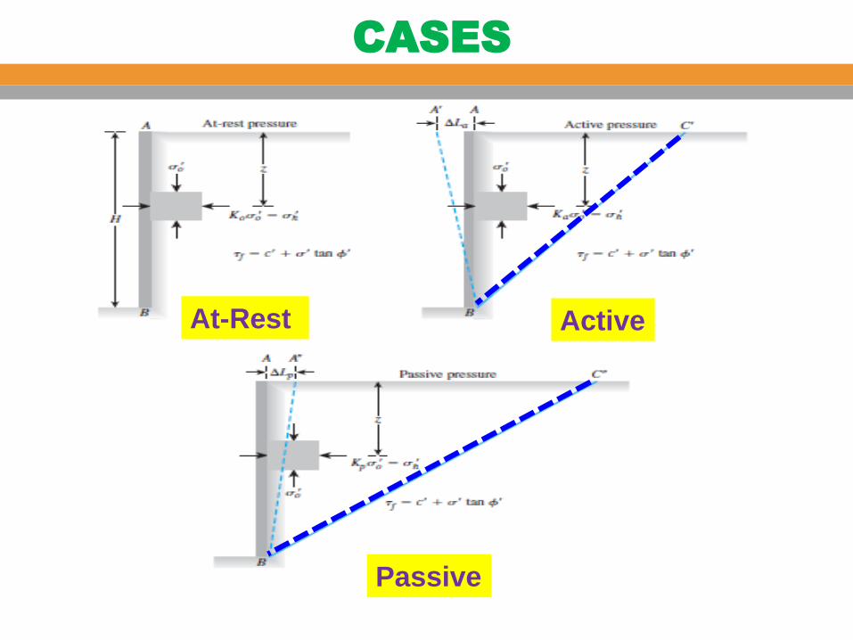
At-Rest Active
Passive
CASES

Lateral Earth Pressure at Rest

Jaky formula For normally consolidated clays and loose sand.
Coefficient of Lateral Earth Pressure K0
Mayne and Kulhawy For Overconsolidated clays

Lateral Earth Pressure at Rest with Water
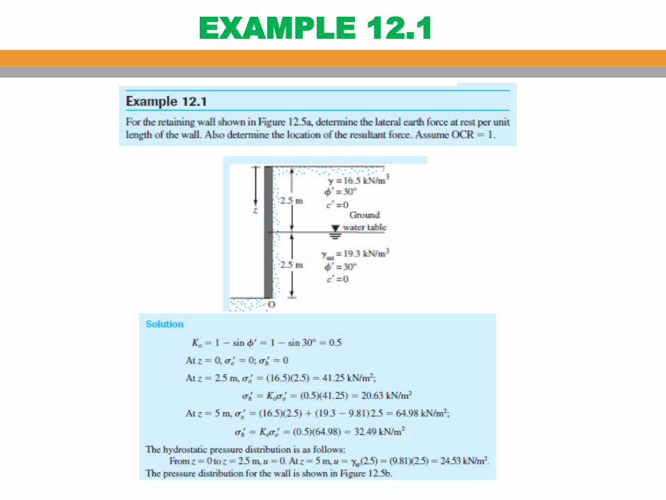
EXAMPLE 12.1

EXAMPLE 12.1

o In the case of active case the soil is the actuating element and in the case of passive the wall is the actuating element.
o If the lateral strain in the soil is ZERO the corresponding lateral pressure is called the earth pressure at-rest. This is the case before construction.
o For either the active or passive states to develop, the wall must MOVE. If the wall does not move, an intermediate stress state exists called earth pressure at rest. (i.e. zero lateral strain).
o For greatest economy, retaining structures are designed only sufficiently strong to resist ACTIVE PRESSURE. They therefore must be allowed to move.
o It may at first seem unlikely that a wall ever would be built to PUSH into the soil and mobilize passive earth pressure.
NOTES

o Typically passive earth pressure is developed by anchor plates or blocks,
embedded in the soil and where the anchor rod or cable tension pulls the anchor into/against the soil to develop passive resistance. Walls are seldom designed for passive pressure.
Active
Wedge
Passive
Wedge
o In most retaining walls of limited height, movement may occur by simple translation or, more frequently, by rotation about the bottom.
NOTES
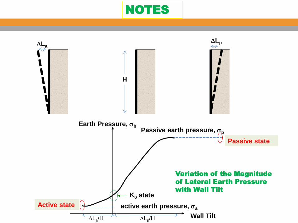
Variation of the Magnitude
of Lateral Earth Pressure
with Wall Tilt
DLa DLp
H
Wall Tilt
Earth Pressure, h
Passive state
Active state
K0 state
Passive earth pressure, p
active earth pressure, a
DLa/H DLp/H
NOTES

Active or passive condition will only be reached if the wall is allowed to yield sufficiently. The amount of wall necessary depends on:-
• Soil type (sand vs. clay) • Soil density (Loose vs. dense) • Pressure (Active vs. passive)
NOTES
1. Rankine’s Theory (No wall friction)
2. Coulomb’s Theory (With wall friction)
o Since late 17th century many theories of earth of earth pressure have been proposed by various investigators. Of the theories the following two are the most popular and used for computation of active and passive earth pressures:.
o Those are usually called the classical lateral earth pressure theories.
o In both theories it is required that the soil mass, or at least certain parts of the mass, is in a state of PLASTIC EQUILIBRIUM. The soil mass is on verge of failure. Failure here is defined to be the state of stress which satisfies the Mohr-Coulomb criterion.
Lateral Earth Pressure Theories

Active vs. Passive Earth Pressures
B
A
Wall moves
towards soil
Wall moves away
from soil
smooth wall
Let’s look at the soil elements A and B during the wall movement.
In most retaining walls of limited height, movement may occur
by simple translation or, more frequently, by rotation about the
bottom.

Assumptions:
o Vertical wall
o Smooth retaining wall
o Horizontal ground surface
o Homogeneous soil
Rankine (1857) investigated the stress condition in a soil at a
state of PLASTIC EQUILIBRIUM.
Developed based on semi infinite “loose granular” soil mass for
which the soil movement is uniform.
Used stress states of soil mass to determine lateral pressures on
a frictionless wall
Rankine’s Earth Pressure Theory

A
v
h
z
• As the wall moves away from the soil,
• Initially, there is no lateral movement.
• v = z
h = K0 v = K0 z
• v remains the same; and
• h decreases till failure occurs.
Active state
wall movement
h
Active
state
K0 state
Active earth pressure
h a
Active Earth Pressure

Sliding surface
Orientation of Failure Planes
(45 + /2)
o From Mohr Circle the failure planes in the soil make (45 + /2)-degree
angles with the direction of the major principal plane—that is, the
horizontal.
o These are called potential slip planes.
The distribution of slip
planes in the soil mass.
o Because the slip planes make angles of (45 + /2) degrees with the
major principal plane, the soil mass in the state of plastic equilibrium is
bounded by the plane BC’. The soil inside the zone ABC’ undergoes the
same unit deformation in the horizontal direction everywhere, which is
equal to DLa/La.

A
v
a 45 + /2
45+/2
Failure plane is at
45 + /2 to horizontal
Active Earth Pressure

Mohr–Coulomb failure envelope defined by the equation
The principal stresses for a Mohr’s circle that touches the Mohr–Coulomb failure
envelope:
active earth
pressure At rest earth
pressure
Decreasing h
Active Earth Pressure
Retaining wall with a vertical back and a horizontal backfill

Active Earth Pressure
Active Earth Pressure
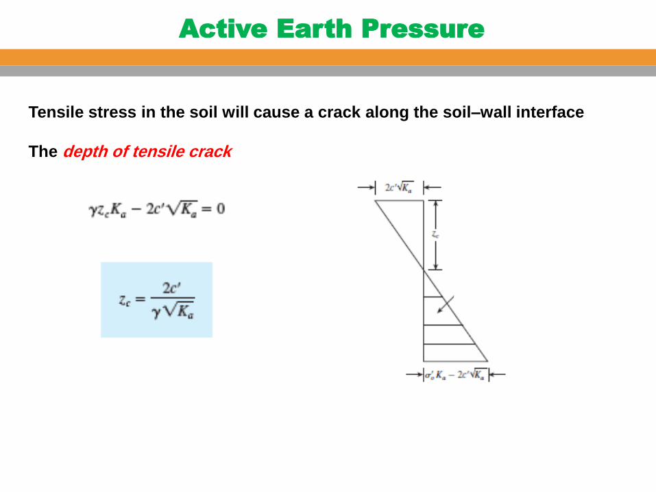
Tensile stress in the soil will cause a crack along the soil–wall interface
The depth of tensile crack

Active Earth Pressure

Active Earth Pressure

Active Earth Pressure
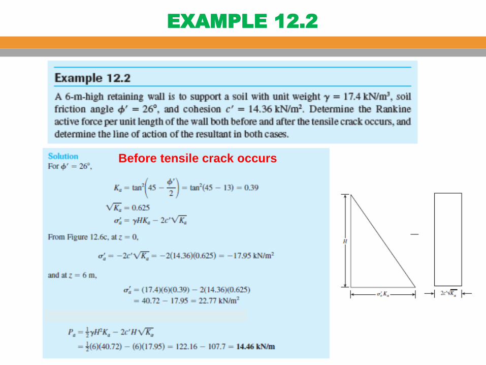
EXAMPLE 12.2
Before tensile crack occurs

EXAMPLE 12.2
After tensile crack occurs

EXAMPLE 12.3
READ EXAMPLE 12.3

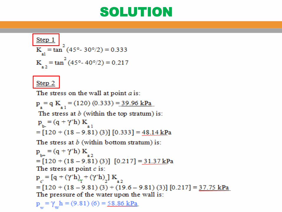
Draw the pressure diagram on the wall in an active pressure condition, and
find the total resultant F on the wall and its location with respect to the
bottom of the wall.
Ka1 = 0.333
Ka2 = 0.217
=(39.96+8.18)/0.333x0.217
=0.333x(18-9.81)x3
=0.217x(19.6-9.81)x3
EXAMPLE
SOLUTION

SOLUTION
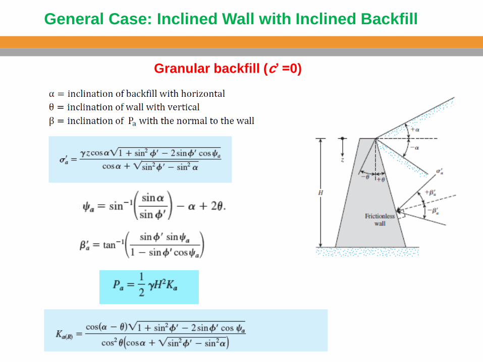
General Case: Inclined Wall with Inclined Backfill
Granular backfill (c’ =0)

Table 12.1 gives the variation of Ka for various values of a, q, and ’
Table 12.2 gives the variation of ba’ for various values of a, q, and
General Case : Inclined Wall with Inclined Backfill
Granular backfill (c’ =0)

Vertical Wall with Inclined Backfill
Granular backfill (c’ =0)
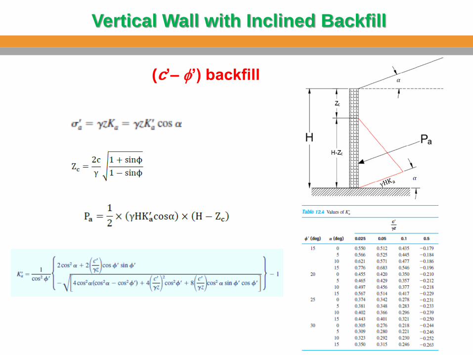
Vertical Wall with Inclined Backfill
(c’– ’) backfill
EXAMPLE 12.4
READ EXAMPLE 12.4
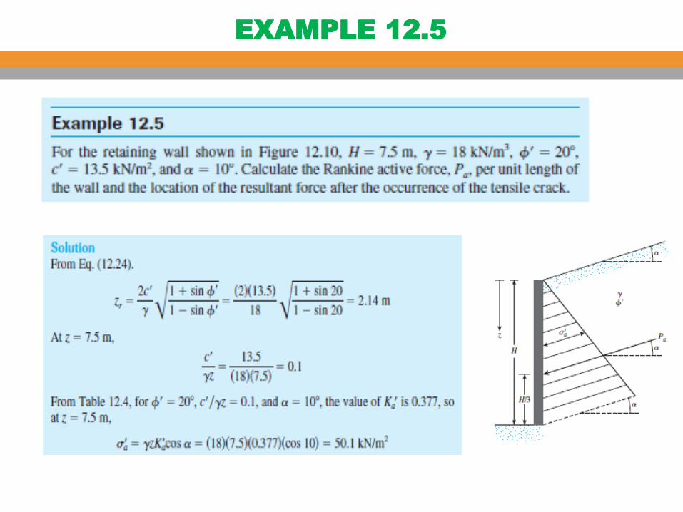
EXAMPLE 12.5

EXAMPLE 12.5

COULOMB’S EARTH PRESSURE

COULOMB’S EARTH PRESSURE

COULOMB’S EARTH PRESSURE

Coulomb’s Active Earth Pressure
Granular backfill (c’ =0)

Coulomb’s Active Earth Pressure
The forces acting on this wedge (per unit length at right
angles to the cross section shown) are as follows:

Coulomb’s Active Earth Pressure
When a = 0o, b =90o, d‘ = 0o, Coulomb’s active earth pressure coefficient
becomes equal to (1-sin ’)/(1+ sin ’), which is the same as Rankine’s active
earth pressure coefficient.

Coulomb’s Active Earth Pressure
The values of the active earth pressure coefficient, Ka for a vertical retaining wall , b =90o
with horizontal backfill a = 0o
are given in Table 12.5

Coulomb’s Active Earth Pressure
The wall friction angle d‘ can be determined in the laboratory by means
of direct shear test. It is assumed to be between ’/2 and 2’/3
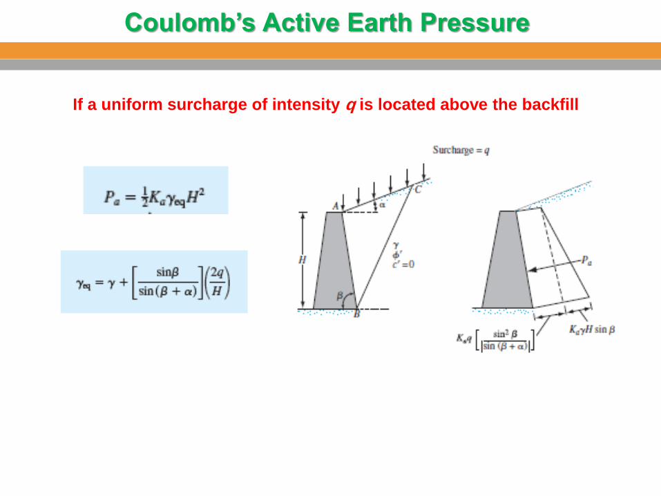
Coulomb’s Active Earth Pressure
If a uniform surcharge of intensity q is located above the backfill

EXAMPLE 12.6
EXAMPLE 12.7
READ EXAMPLE 12.7

Lateral Earth Pressure Due to Surcharge
Line load of intensity q/unit length
Because soil is not a perfectly elastic medium. The modified forms of the
equation above are :
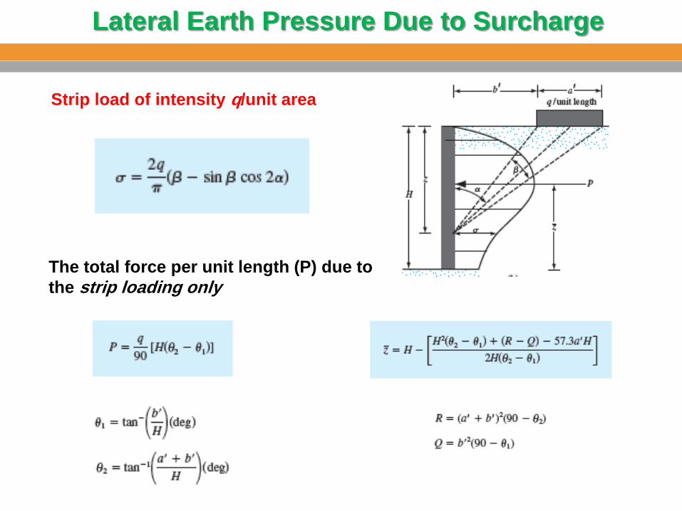
Strip load of intensity q/unit area
The total force per unit length (P) due to
the strip loading only
Lateral Earth Pressure Due to Surcharge

EXAMPLE 12.8

EXAMPLE 12.9

EXAMPLE 12.10

• Initially, soil is in K0 state.
• As the wall moves towards (pushed into) the soil mass,
• v remains the same, and
• h increases till failure occurs.
Passive state
B
v
h
wall movement
h
K0 state
Passive state
Passive earth pressure
h p
Passive Earth Pressure
(45 - /2)
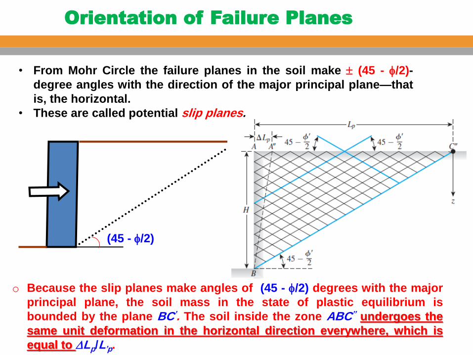
• From Mohr Circle the failure planes in the soil make (45 - /2)-
degree angles with the direction of the major principal plane—that
is, the horizontal.
• These are called potential slip planes.
o Because the slip planes make angles of (45 - /2) degrees with the major
principal plane, the soil mass in the state of plastic equilibrium is
bounded by the plane BC’. The soil inside the zone ABC’’ undergoes the
same unit deformation in the horizontal direction everywhere, which is
equal to DLp/L’p.
Orientation of Failure Planes

v
Initially (K0 state)
Failure (Passive state)
• As the wall moves towards the soil,
increasing h passive earth
pressure
At-rest earth
pressure
p
Rankine’s passive state
Passive Earth Pressure

v p
B
v
p
90+
Failure plane is at
45 - /2 to horizontal
45 - /2
Failure plane
Passive Earth Pressure

C
Passive Earth Pressure
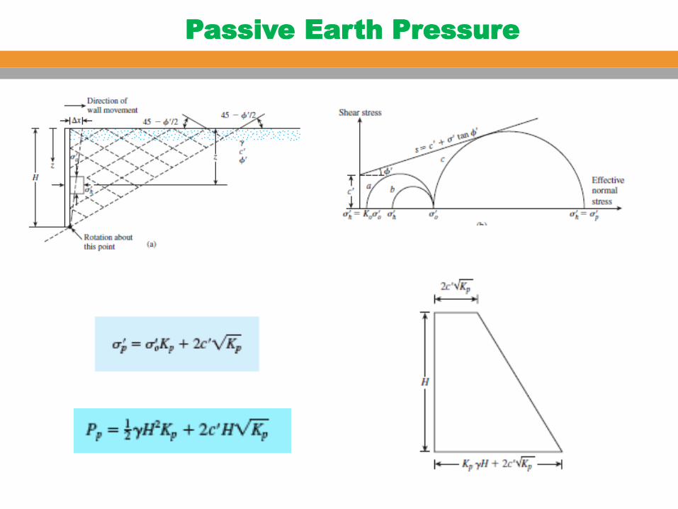
Passive Earth Pressure

EXAMPLE 12.13
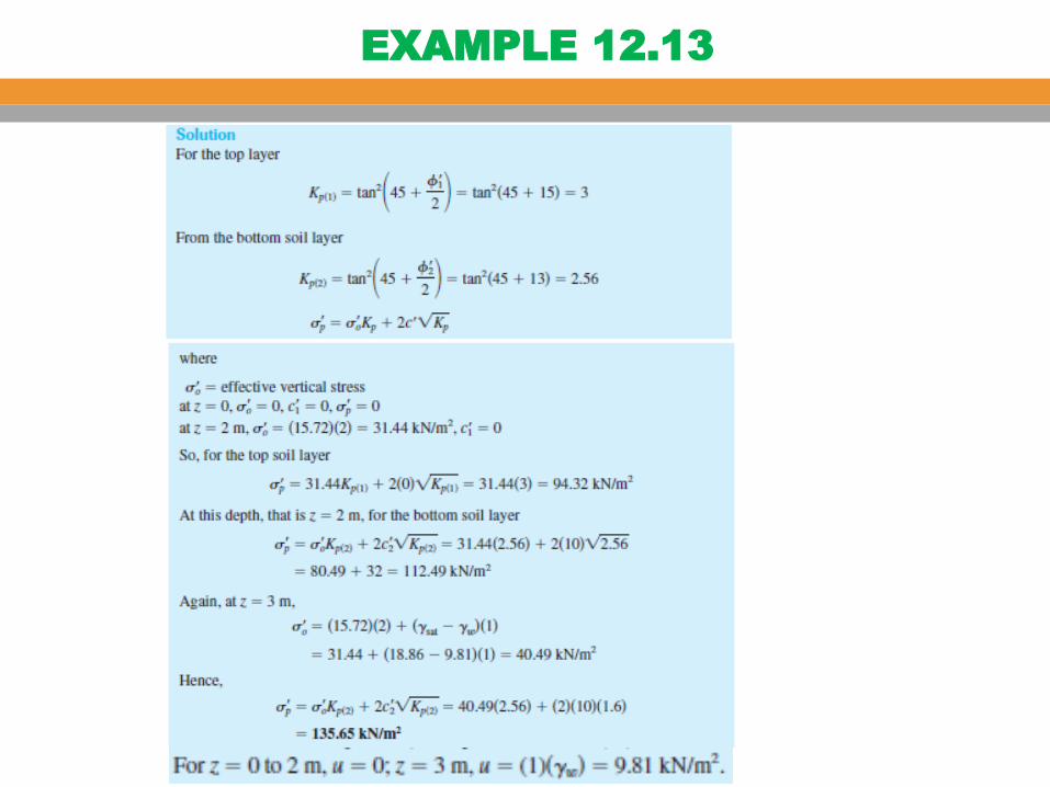
EXAMPLE 12.13

EXAMPLE 12.13

Rankine Passive Earth Pressure
Vertical Wall and Inclined Backfill
Granular backfill c’ = 0
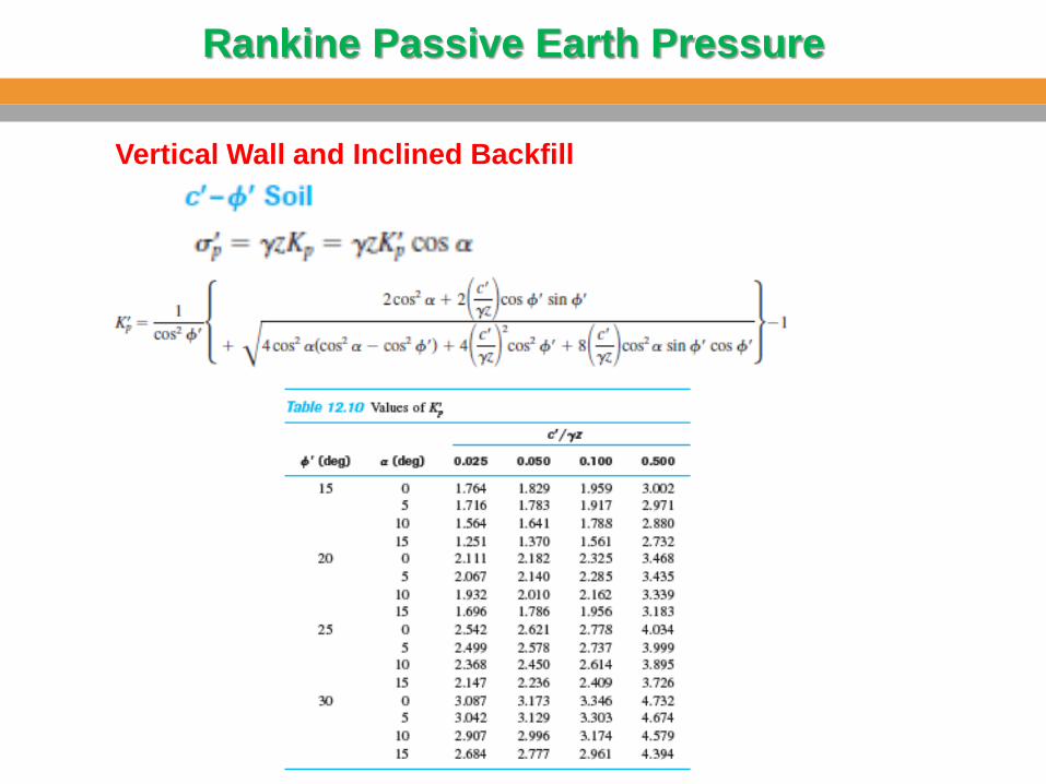
Rankine Passive Earth Pressure
Vertical Wall and Inclined Backfill

Coulomb’s Passive Earth Pressure

Coulomb’s Passive Earth Pressure

Comments on the Failure Surface Assumption
for Coulomb’s Pressure Calculations
The fundamental assumption in Coulomb’s pressure calculation methods for active
and passive pressure is the acceptance of plane failure surface. However, for walls with friction, this assumption does not hold in practice. The nature
of actual failure surface in the soil mass for active and passive pressure is shown in
Figure below, respectively (for a vertical wall with a horizontal backfill).
Note that the failure surface BC is curved and that the failure surface CD is a plane.

Comments on the Failure Surface Assumption
for Coulomb’s Pressure Calculations
Although the actual failure surface in soil for the case of active pressure is
somewhat different from that assumed in the calculation of the Coulomb
pressure, the results are not greatly different.
However, in the case of passive pressure, as the value of d’ increases,
Coulomb’s method of calculation gives increasingly erroneous values of Pp .
This factor of error could lead to an unsafe condition because the values of Pp would become higher than the soil resistance.
Several studies have been conducted to determine the passive force Pp ,
assuming that the curved portion BC in is an arc of a circle, an ellipse, or a
logarithmic spiral (e.g., Caquot and Kerisel, 1948; Terzaghi and Peck, 1967;
Shields and Tolunay,1973; Zhu and Qian, 2000).

Caquot and Kerisel Solution for Passive Earth
Pressure (Granular Backfill)

Caquot and Kerisel Solution for Passive Earth
Pressure (Granular Backfill)
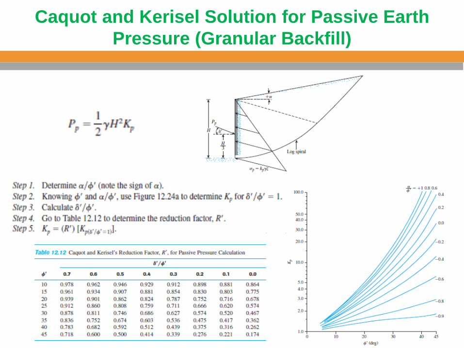
Caquot and Kerisel Solution for Passive Earth
Pressure (Granular Backfill)

EXAMPLE 12.14

The soil conditions adjacent to a sheet pile wall are given in the Figure below. A
surcharge pressure of 50 kN/m2 being carried on the surface behind the wall.
For soil 1, a sand above the water table, c′ = 0 kN/m2 and ′ = 38o and ɣ = 18 KN/m3.
For soil 2, a saturated clay, c′ = 10 kN/m2 and ′ = 28o and ɣsat = 20 KN/m3.
•Calculate Ka and Kp for each of soils (1) and (2).
•Complete the given table for the Rankine active pressure at 6 and 9 m depth behind
the wall shown in the Figure.
•Complete the given table for the Rankine passive pressure at 1.5 and 4.5 m depth
in front of the wall shown in the Figure.
q= 50 kN/m2
kN/m2
W.
T Soil (2)
Soil (1) 6.0
m
3.0
m
1.5
m
EXAM

Depth (meter)
Soil
Active Pressure (kN/m2)
0 1
6 1
6 2
9 2
Passive Pressure (kN/m2)
0 1
1.5 1
1.5 2
4.5 2
Table . Active and passive earth pressures on sheet pile wall

q= 50 kN/m2
kN/m2
Active Passive
W.
T Soil (2)
Soil (1) 6.0
m
3.0
m
1.5
m
SOLUTION
Soil 1: Ka = (1-sin 38)/(1+sin 38) = 0.24
Kp = 1/Ka = 4.17
Soil 2: Ka = (1-sin 28)/1+sin 28) = 0.36
Kp = 1/Ka = 2.78
SOLUTION

Depth (meter)
Soil
Active Pressure (kN/m2)
0 1 0.24 x 50 = 12
6 1 0.24 x (50 + 18 x 6) = 37.9
6 2 = 44.9
9 2 = 85.33
Passive Pressure (kN/m2)
0 1 = 0
1.5 1 4.17 x 18 x 1.5 = 112.6
1.5 2 = 108.4
4.5 2 = 222.93
SOLUTION
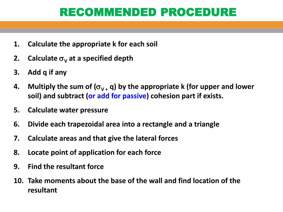
1. Calculate the appropriate k for each soil
2. Calculate V at a specified depth
3. Add q if any
4. Multiply the sum of (V + q) by the appropriate k (for upper and lower soil) and subtract (or add for passive) cohesion part if exists.
5. Calculate water pressure
6. Divide each trapezoidal area into a rectangle and a triangle
7. Calculate areas and that give the lateral forces
8. Locate point of application for each force
9. Find the resultant force
10. Take moments about the base of the wall and find location of the resultant
RECOMMENDED PROCEDURE