
Elastic Lateral-Torsional Buckling Load on Circular Fixed ...

\; -
l'
LATERAL AND LOCAL BUCKLING OF I :BBAMS IN PLASTIC BANGE
(A part from the PhoDo dissertation of Ching Hwm Yang)
/

IIII~'
I.,
55
(5) L.flTERAL AND LOCAL BUCKLING- OF I BEM~1S IN PLAsrrI(; RANGE
Shanley, in his paper on inelastic column theory. (10)
has proved that an ideal column will start to bend e,t a
.load equal to its tangent modulus load. According to the
average stress and strain· diagram of structural steel, the
"'slope of the curve in the plastic range before strain har-
dening is zero. That leaves the criterion of the tangent
modulus load ~~thout real meaning in the limiting case.
In columns loaded with a slight ecC'entrici ty (Dro-
. vided the- columns are made of a material which exhibits the
above-stated zero slope throught the plastic range), the
average compression stress on the column cross section can
never reach the yield point.
Ideally loaded columns made of perfectly plastic
material are actuallyunstablewhEln the average stress
reaches yield point. It may collapse at any instant when
the average stress reaches the yield point .regardless what9
length the column has.
. ,
F J\ r :;, ,".I G. / . ...Y'l)
. I

56
This statement can be demonstrated as follows:
Let Po be the load at which the average compression
stress on the column reaches the yield point
" Po = a CfYll
where "a " equals the total cross section area of the
column.
Suppose the ideal column is loaded with axial load Po'
and we make a virtual displacement along the column as the
dotted lines show aboveo Take a cross s~ctlon A,A. Let
the corresponding displacement at that section be Yo. Then
the section will be under ~otal axial load Po and a
moment IvI = Po "-yo. In order to balance both the mome nt and
the axia.l load, the stress distribution must be chane:;ed from
jk to hi. But the stress cannot be any higher the cry if
the material is perfect~y plastic. The stress distributed
in the shaded area in the. above Fig. 1s therefore impossibleo
The external moment will not be balanced. It is obvious
that the column will" collapse in bending at once.
This would lead to a conclusion that a member shoUld
never carry co~pressive stress to the yield point if it
is made of materials that have perfect plasticity after
yielding.
In simple plastic theory, sections in structural
members at which stresses exceed the yield point are assumed

-
57
to develop "plastic hinges". In the case of "I" sections
there is, from the above discussion, a possibility of
bucklin2, of the compression flange in the region of the
so-called tlplastic hinge". The buckling of the compression
flange would l~turally reduce the value of plastic hinge
moment. Therefore the' problem of instability of structural
steel members becomes very important in the simple pI Bstic
theory of structural design.
Stress and strain curves for ordinary tension or com-• I
pression tests do not give enough information for the
analysis of stability problems. in the plastic range. None
of the metals used in engineering structures are perfectly
plastic 2nd an ordinary stress and strain diagram usually
gives no information of the relation between stress and
strain rate in pIa sti c ranGe. The mechani sm of yielding of
the metal also affects the bucklinc ; strength of the com-
pres sian mera.ber.
Take the previous column; the moment at section Al A2
may be very STIlB.ll at the beginning. If this moment makes
the column bend, then the strain rate at slde .11 will
naturally be higher than at side A2- ~he stress at side
Al wil.l be raised by the higher strain rate that makes the stress
distribution over the cross section possible to balanoe the external
moment, ?nd the column wil] thaD bend and shorten at the same
time until the strain hardening range is reached. I

58
In a si.-rnple tension or compression test of a structur2.1
steel one will find that Luder's lines do not all appear at
onee when the yield point is reached. Yield lines'usually
are initiated in srnne places and then gradually spread over
the whole- spcc:i.meno· While the yield lines are progressing,
the region where the yield lines were initiated might~
have develo:?ed all its plastic strain and reached the strain
hardenin;:=; l'anse 10ca11 yo The specimen can not be considered
as perfectly plastic even though the portion of the stress
•and strain diagram is observed to be parallel to the abscissa.
The co:nprGssion member can therefore be expected to have a
buckling strength of the tanE:ent modulus load in the plastic'
range where the tangent of the stress and strain curve is
chosen at the starting point of the strain hardening range.
E.
F/G~ IV 3/
HoVl does this yieldinL process affect the buckline;
strength of a compression member? It can be demonstrated
by the following analogi cal eX8l!Dle:

.-----.~-l\1\
I I\r-~·--Uy 1\
! i \ rr__________.l.L:.- __
CI. I. I II I, ;.. i: • I II I
, _r-'-J-'--L-~..L-J.t_t ~ ; '1 D
IIIi
!II ,,
A '-r-.-r-.,-,c--.-~,_,__._,.__r_'-,i' .B
n
A 59
(0.) (b)
FIG. IV 32
Suppose the compression member is slightly tapered on one
side, as shown in dotted lines in above Fig. IV.32(a).
Instead of having a uniform cross section throughout the
length, the stress distribution along the member will be as
shown in dotted lines Fig. IV.32(b). The root section
AB will reach the yield point first, and as stress increases
the yielding zones will progress to reach the top section
CD. If t'ne mechanical, properties of the material are homo-
geneous every section will be strain hardened as soon as
the stress exceeds o-yo During this progression of yield.ing
the strain lwrdening zone and elastic zone are separated by
only an inf'in5- te simally thin plane which has peJ'fe ct
plasticity. In this case the cO:':lpression member will,,'
however, have a buckJing strength at ~ast equal to the
tangent :nodulus load. The tangent of the stress and strain
diagram is selected at the point of the ~tartlng of the
strain hardening region as before.

60 .
To summarize the above discussion there may be two
extrer,le case s:
Fil~st, if the, rraterial is perfectly plastic and stressed
to the yield point, the compression member yIill be
and will bend no matter what the L Ir ratio of the
unstable
com-
pres~,ion me;~lber is. Secondly, if thE; ~)last:i.c flow in a
compr8ss1on Yi18mb3:L' is established plane by plane and all
the '018.1188 ,(.:etstrain hardened 3.8 ':)lastic flow oroc-resses~ . ~ G
the CO:',l131"'833ion menber YJill then have a blYJ.ckllng strenc;th
of tangent ~odulus load as defined above.
The practical case may lie between the above two
extremes. Apparently the tangent ~odulus load defined as
above" vJill be come the uppe:r lind t 'of the buckling s tren[.;th-
for the . .co~presslon member. For rectaneular sections the
t[;mgent :nodulus load can be calculated as follows:
t
FIG. IV33-------~----------
•
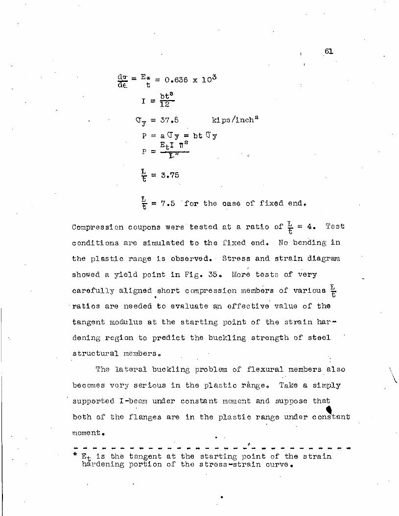
61
x 103E* = 0.636t
btG
I =:rn-~y = 37.5 kips!inch2
P = a cry = bt cryEtI it la
p = ~ 1.:3 •
d~ -dE:'-
~ = 3.75
L~ = 7.5 'for the oase of fixed end.
Compression coupons were tested at a ratio of ~ = 4. Test
conditions al~e simulated to the fixed end. No bending in
the plastic range is observed., Stress and strain diagr~l
showed a yield point in Fig. 35. More tests of very
carefully aligned.short compression members of various ~
ratios are needed to evaluate an effective value of the
tangent modulus at the starting point of the strain har-
dening region to predict the buckling strength of steel
structural mcmbers o
The lateral buckling problem of flexural members also
becomes vOl'y serious in the plastic rangeo Take a simply
\\
\
supperted I-beam under constant mornent and suppose that,both of the flanges are in the plastic range under constant
moment. . .~- - - ~ ~ - - - - - - ~ -- - - ~ ~ - - - - - - - - - - --* Et 1s the tangent at the starting point· of the strain
hardening portion of the stress-strain curve •
•

62
.( ,~----.-----.--.-- ..-..-. -'-"--=='~===:-'=~='::~l \,I I IIJ \:1-'-------.---~·-···-'---··-·-----··-.I I--- "-.--'-H .
FIG. J\/-.' .34-----
According to the first assumption that the yielded part of
the beam is perfectly plastic, it is obvious that the
lateral buckling strength of the beam will be ,equivalent to
a beam considering only the elastic part of the same be.ara
under the same moment. According to the assumption that
the yielded part of the beam will have a tangent modulus
strength, the lateral buckling strength of this beam can be
computed by regarding the beam as n~ving different moduli
in the elastic rErt and plgstic part. The actual lateral
buckling strength of s~c4 a beam is expected between the. above
two val~eso
The central· portion of the tested continuous beams bet·wee·n
the two loading points were all under constant moment. It
is natural that when both flanc;es of this portion enter the
plastic range~ the lateral buckling strength of the beam
will be greatly reduced.~
. I"evel bars were mounted perpendicular to the beam a.xis
to measure the rotatHm of the beam. Curves are shown in
Fig. 3Qo Par 8WF40section it is soen that lateral deformation

63
started bet~veen Vol = 45 kips to W = 50 kips. It was at this
regio~as observed from both t~e white wash and strain
gage~ that, the flanges went to the plastic range. Fig. 37
is a picture of beam B7 taken after the test, wluch shows
that the central span buckled laterally in tvvo half wave
Ie ngths.
Dial gages also were mounted near the supports between
the tension and compression flanges to measure the local
buckling in Beam B4 and B5 as shown ih Fig. 38. Beam B7
has thin..Yler flange thickness than all the rest of the
beams. The compression flange buckled very severely as
shown in FiG- 39 0
(6) SH'~;A!i- FAILURE IN EECTANGULAR BfAIWS OR IN VlEBS OF I-·
SECTIONS Dlffi TO TRANSVERSE LOAD
In the elastic beam theory, when a bending nlember is
under transverse load, maximum shear stress is developed at
the neutral axis. This shear stress is distributed as a
parabolic fun~tion across the section accol"'ding to the
theory. As the beam is loaded to the plastic Fange this
prediction of shear stress by the elastic theory is of
course no' lonGer valid. This shear stress, when its value
becmnes comparatively high, may initiate yielding in the
web of the beam earlier than that of' the normal stress in
the outer fibre of the flange_ The problem is discussed in-
the following three different cases:

(I)
(II)
Table' of Contents,
Synopsis
Introduction
Page
1
1
(III) Description of Experimental Program
(1) Test set-up
(2) Preparation of specimen
(3) Strain gages, deflection gages andlevel bars
(4) Test procedure
3
5
7
10
( IV) Presentation and Analysis of Test Resul ts· 12•
(1) Bending strength of I-sectionsunderpure moment 12
a) M~ relation of bending membors
b) Strain.distributj.on in plasticbending
(2) Initial yield strength of the continuous beams
a) Residual stress
b) Stress concentration
12
17
18
18
24
(3) Ultimate strength of continuous beam~, 31
a) Strain hardening effect of structural steel and the Ultimate strengthof continuous be~s 32
b) The influence of end restraint onthe Ultimate strength of continuousbeams 38
(4) Deflection of.beams in plastic range 41
a) Method of simple plastic theory
b) Method of numerical integration
42
46

0) Method of mathematical integrationfor I-sections 48
d) Simplified method of mathematicalintegration for I-sections 50
(5 )
(6)
Lateral and local buckling of I-beamsin plas ti c radge
Shear failure lin rectangular beams orin webs ofr-sections due to transverse load
55
63
(v)
(\11 )
Conclusi ons
References
73
74
(VrI) Appendixes
A., Coupon test ~esults 77
B. Residual stresses 82
c. Determination of initial yiel~ strengthin experimental load-deflection curves 85
(VIII) Nomenclature 87

... -... -..
Strain in inches per. inch
C COMPRESSION STRESS-STRAIN CURVE FOR AN 8WF40 BEAMFig. 35
I
,'";.,.. ! I
'" 1;). '".. . . .'" I o· I;) 'J v I .
t ?"" "'~
.~I;) u I;) v 1
'"..Ia) "''''
I;)'" '" v I v JJ",(
-I ! f I 1
~. . ,
II
p-.'"
°1, j I J II
~u~ ,
~ I
! If \: It If- .I• I
~
V II ] I , i f,, /
I I
J t! •
I J II
Specimen WI Specimen W2 Specimen W3 Specimen W4 I Specimen W5I' I
.'
1 r ! / !1
I
If I t f II
IrJ
V ~I-
1 .<; I Q J ~ .
f I I II--
t-_..-
! t 10
. I I
{ f f fI
,I I I IJ 9 P ,
il II II IIoI... 0.00\ ~
2.5
5.0
7.5
\0.0
12.5
15.0
27.5
35.0
25.0
32.5
37.5
40.0
30.0
22.5Stress
20.0(kips/in2
)
175

I,
"''''
~~ --0
I u ~v
II I ~(
\ II 0 I
I~ 0
I
II
--- 37.5 ---- I
I ---j--
I
I( I
Ii
I ( I
en i.9- (- . I !~ I
I
25.0 " - . I
.£I
- - I~ I0 I
0 (- - II
.-J I II-p
I I.I I
I I II 12.5 -- ---,.-.----- I ---r- -'I I
I
III
-0.015 -0.01 -0.005 a 0.005 0.0\
Lateral Rotation (Angle in Radians)
Beam 3
0.015
F ro 3CIC)ly ,0

F io ?16 b":J -
0.02
-- -+------~
0.015
----I-------i-----
--II-~~------
37.5 I----t,----- ~------~------------------ -------_:..
III
~ ,I
.9-
~ 25.0~--o--":"'-o--- -- -----~t~-~-~r---~---- -~-
~ I
I
I---12.5
-r------ 50.0
-\
iIII
-IIi---
I
I
- 0.005 0 O.OO? 0.01
Lateral Rotation (Angle In Radians)
Beam 4
i---1---------\II
-0.01

Fiq 36c
.0.0250.02
-------,1-- ------I
I :i . I
---- -1--------- -j-'-- ----.-- --!-.------ --- _. --- ·--1------------I I
i I
--- _. --- -.-_.- - '-j
0.005 0.0I 0.015
Lateral Rotation .,. (Angle in Radians)
Beam 5
o
25.0- 0
'Uoo
...J
o
!------- 37.5 I----h
I·I
-0.005
-----;----50.0f---~
,iiI------1'-- c::.-
II,
I- --- -~--- - ---- -- --- ------ ---1-
,
i
I Iiii -------.-- -._-.------ 12.5 --- -- ------------------~--------- --1------ --- ----.-.-. -1---· -- ----_.-------1.---.---
o 0 I..0
1I!!!
!

vo
-------J------~--- 50.0
·0
o
I-------+-------!---- 37.5 )--+,)-----I-------+--------t------·-+---------'1
S) .
._-----+-----j--
V)
a.~
c - 25.0 I-!-I----+--------+-------+------+---------\
'0oo
...J
1--------~------+------12.5 --------I--------f--------l---------J--------l
Lateral Rotation (Angle in Radians)Beam 7.'
-0.01 -0.005 o 0.005 0.01 0.015 0.02
Fir) 36d

I I
~==o=+=!;;;t~.. ==r=i====r=t=:A77==7F=i=!=b=l
500
Moment(inch -kips)
1000
Deflection in inches
Beam '4
.. ,\
'. '"~
IV(:)
)~ '"o o.It5" v 0
. c· o~~ :>.y: ~
I -.
.~0\.~b c a-
p--
;>~ ..
1. I
I ,I
i II II
,1 t
,.-'. :. ,-
£ .• ---- ~ ... . 1 "_. "} !
)
o~ j0.01
1500
2000
2500
•
Deflection in inches
Beam ~
Fig 36
~ 0
'" a0 , - I
0 "'Uv
0
~0
..:. ...~ .a
(. 9"
~b t\~ aIi
~..
c
IIi
C·
II
-J I
c·
;> - ?
500
0 1_ ---J0.0\
1000
1500
2000
. Moment
(inch -kips)

,
t
J'1g. 39


