
Last Revision: January 2021
20
October 2011 Score Energy Products Inc. 9821 - 41 Avenue Edmonton, Alberta, Canada T6E 0A2 Phone: (780) 466-6782 Fax: (780) 465-6979 www.scorevalves.com January 2021 Last Revision: January 2021
Transcript of Last Revision: January 2021
October 2011Score Energy Products Inc.9821 - 41 AvenueEdmonton, Alberta, Canada T6E 0A2
Phone: (780) 466-6782Fax: (780) 465-6979www.scorevalves.com
January 2021Last Revision: January 2021
33334
444444
555566666666
678
88
88999
1010111112
13
1314141414141414
151516171819
. . . . . 20
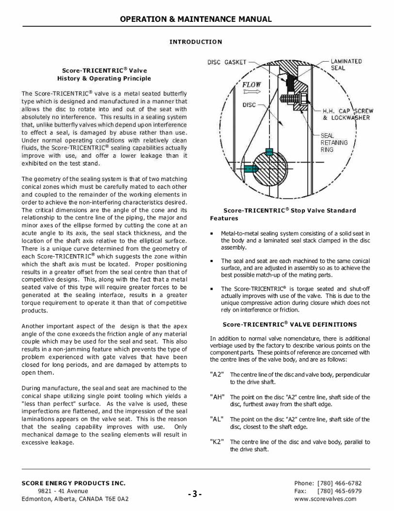
LAMINATED SEAL
N
H.H. CAP CREW & LOCKWA
t
HER
SEAL RETAINING / RING
./
DISC GASKET
FLOW
DISC
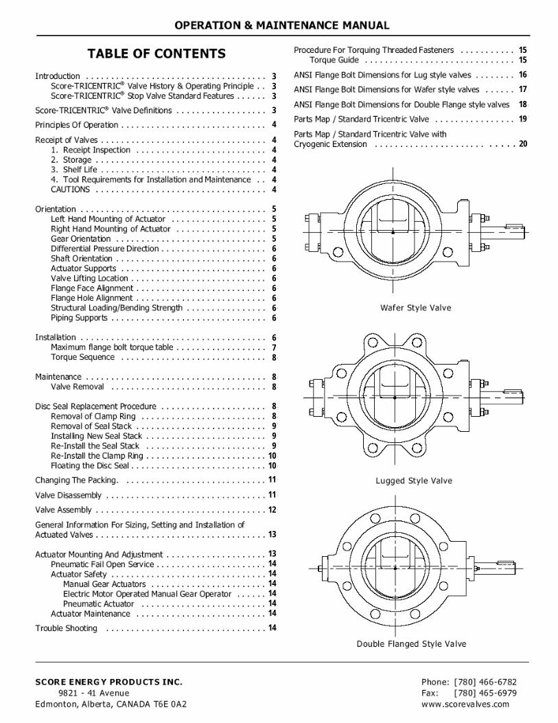
OPERATION & MAINTENANCE MANUAL
INTRODUCTION
Score-TRICENTRIC® Valve History & Operating Principle
The Score-TRICENTRIC® valve is a metal seated butterfly type which is designed and manufactured in a manner that allows the disc to rotate into and out of the seat with absolutely no interference. This results in a sealing system
that, unlike butterfly valves which depend upon interference to effect a seal, is damaged by abuse rather than use. Under normal operating conditions with relatively clean fluids, the Score-TRICENTRIC's sealing capabilities actually improve with use, and offer a lower leakage than it exhibited on the test stand.
The geometry of the sealing system is that of two matching
conical zones which must be carefully mated to each other and coupled to the remainder of the working elements in order to achieve the non-interfering characteristics desired. The critical dimensions are the angle of the cone and its relationship to the centre line of the piping, the major and minor axes of the ellipse formed by cutting the cone at an acute angle to its axis, the seal stack thickness, and the location of the shaft axis relative to the elliptical surface. There is a unique curve determined from the geometry of each Score-TRICENTR IC® which suggests the zone within
which the shaft axis must be located. Proper positioning results in a greater offset from the seal centre than that of competitive designs. This, along with the fact that a metal seated valve of this type will require greater forces to be generated at the sealing interface, results in a greater torque requirement to operate it than that of competitive products.
Another important aspect of the design is that the apex angle of the cone exceeds the friction angle of any material couple which may be used for the seal and seat. This also results in a non-jamming feature which prevents the type of problem experienced with gate valves that have been closed for long periods, and are damaged by attempts to open them.
Duri ng manufacture, the seal and seat are machined to the conical shape utilizing single point tooling which yields a "less than perfect" surface. As the valve is used, these imperfections are flattened, and the impression of the seal laminations appears on the valve seat. This is the reason that the sealing capability improves with use. Only mechanical damage to the sealing elements will result in
excessive leakage.
Score-TRICENTRIC® Stop Valve Standard Features
• Metal-to-metal sealing system consisting of a solid seat in the body and a laminated seal stack clamped in the disc assembly.
• The seal and seat are each machined to the same conical surface, and are adjusted in assembly so as to achieve the best possible match-up of the mating parts.
• The Score-TRICENTRIC° is torque seated and shut-off actually improves with use of the valve. This is due to the unique compressive action during closure which does not rely on interference or friction.
Score-TRICENTRIC® VALVE DEFINITIONS
In addition to normal valve nomenclature, there is additional verbiage used by the factory to describe various points on the component parts. These points of reference are concerned with the centre lines of the valve body, and are as follows:
"A2" The centre line of the disc and valve body, perpendicular to the drive shaft.
"A1-1" The point on the disc "AZ" centre line, shaft side of the disc, furthest away from the shaft edge.
"AL" The point on the disc "A2" centre line, shaft side of the disc, closest to the shaft edge.
"K2" The centre line of the disc and valve body, parallel to the drive shaft.
SCORE ENERGY PRODUCTS INC. 9821 - 41 Avenue
Edmonton, Alberta, CANADA T6E 0A2 - 3 -
Phone: [780] 466-6782 Fax: [780) 465-6979 vv ww .sco re va Ives .com
- 3 -
OPERATION & MAINTENANCE MANUAL
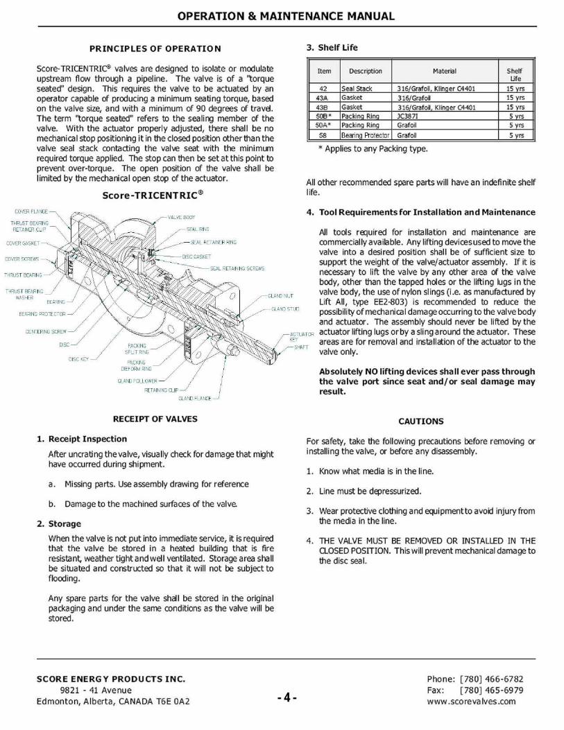
COVER GASKET
COVER SCREWS
THRUST BEARING
THRUST BEARING WASHER
BEARING
THRUST BEARING RETAINER CLIP
COVER FLANGE
BEARING PROTECTOR
CENTERING SCREW
DISC
DISC KEY
GLAND FOLLOWER
RETAINING CLIP
GLAND FLANGE
PACKING SPLIT RING
PACKING DIEFORM RING
VALVE BODY
zA- SEAL RING
SEAL RETAINER RING
DISC GASKET
SEAL RETAINING SCREWS
GLAND NUT
GLAND STUD
ACTUATOR KEY
SHAFT
3. Shelf Life
Item Description Material Shelf Life
42 Seal Stack 316/Grafoil, Klinger C4401 15 yrs
43A Gasket 316/Grafoil 15 yrs
438 Gasket 316/Grafoil, Klinger C4401 15 yrs 508 • Packing Ring 3C3871 5 yrs
50A' Packing Ring Grafoil 5 yrs
58 Bearing Protector Grafoil 5 yrs
- Applies to any Packing type.
All other recommended spare parts will have an indefinite shelf life.
4. Tool Requirements for Installation and Maintenance
All tools required for installation and maintenance are commercially available. Any lifting devices used to move the valve into a desired position shall be of sufficient size to support the weight of the valve/actuator assembly. If it is necessary to lift the valve by any other area of the valve body, other than the tapped holes or the lifting lugs in the valve body, the use of nylon slings (i.e. as manufactured by Lift All, type EE2-803) is recommended to reduce the possibility of mechanical damage occurring to the valve body and actuator. The assembly should never be lifted by the actuator lifting lugs or by a sling around the actuator. These areas are for removal and installation of the actuator to the valve only.
Absolutely NO lifting devices shall ever pass through the valve port since seat and/or seal damage may result.
CAUTIONS
For safety, take the following precautions before removing or installing the valve, or before any disassembly.
1. Know what media is in the line.
2. Line must be depressurized.
3. Wear protective clothing and equipment to avoid injury from the media in the line.
4. THE VALVE MUST BE REMOVED OR INSTALLED IN THE CLOSED POSITION. This will prevent mechanical damage to the disc seal.
PRINCIPLES OF OPERATION
Score-TRICENTRIC5 valves are designed to isolate or modulate upstream flow through a pipeline. The valve is of a "torque seated" design. This requires the valve to be actuated by an operator capable of producing a minimum seating torque, based on the valve size, and with a minimum of 90 degrees of travel. The term "torque seated" refers to the sealing member of the valve. With the actuator properly adjusted, there shall be no mechanical stop positioning it in the closed position other than the valve seal stack contacting the valve seat with the minimum required torque applied. The stop can then be set at this point to prevent over-torque. The open position of the valve shall be limited by the mechanical open stop of the actuator.
Score-TRICENTRIC®
RECEIPT OF VALVES
1. Receipt Inspection
After uncrating the valve, visually check for damage that might have occurred during shipment.
a. Missing parts. Use assembly drawing for reference
b. Damage to the machined surfaces of the valve.
2. Storage
When the valve is not put into immediate service, it is required that the valve be stored in a heated building that is fire resistant, weather tight and well ventilated. Storage area shall be situated and constructed so that it will not be subject to flooding.
Any spare parts for the valve shall be stored in the original packaging and under the same conditions as the valve will be stored.
SCORE ENERGY PRODUCTS INC. 9821 - 41 Avenue
Edmonton, Alberta, CANADA T6E 0A2 - 4 -
Phone: [780] 466-6782 Fax: [780] 465-6979 www .sco reva Ives .com - 4 -
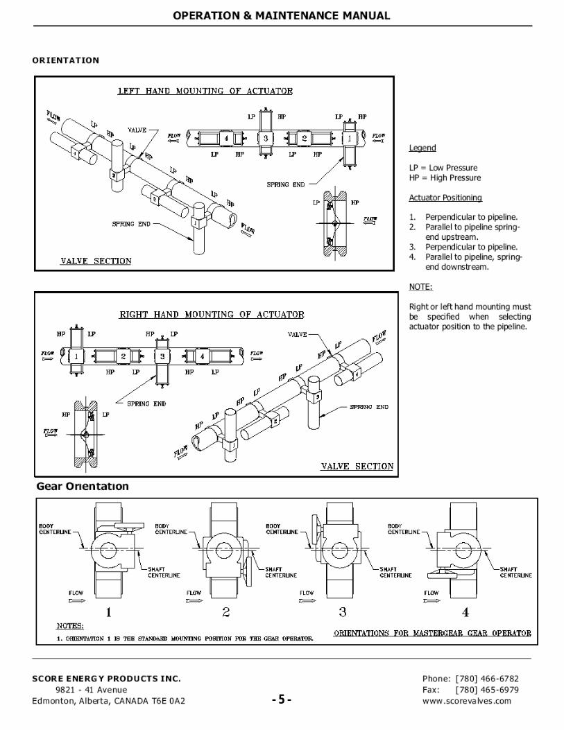
Right or left hand mounting must be specified when selecting actuator position to the pipeline.
Gear Onentation
RIGHT HAND MOUNTING OF ACTUATOR
flow
HP
11
LP HP
—0-
11
MOT 1:=>
now
HP LP
SPRING END
NP
jf SPRING END
NP
VALVE SECTION
VALVE
1 2 3 4
BODY CENTERLINE
SHAFT CENTERLINE
BODY CENTERLINE
SHAFT CENTERLINE
BODY CENTERLINE
SHAFT CENTERLINE
SHAFT CENTERLINE
BODY CENTERLINE
FLOW FLOW FLOW FLOW C7 r=7
NOTES: ORIENTATIONS FOR MASTERCEAR GEAR OPERATOR
1. ORIENTATION 1 15 TEE STANDARD MOUNTING POSITION FOR THE GEAR OPERATOR
OPERATION & MAINTENANCE MANUAL
ORIENTATION
Legend
LP = Low Pressure HP = High Pressure
Actuator Positioning
1. Perpendicular to pipeline. 2. Parallel to pipeline spring-
end upstream. 3. Perpendicular to pipeline. 4. Parallel to pipeline, spring-
end downstream.
NOTE:
SCORE ENERGY PRODUCTS INC. [780] 466-6782 9821 - 41 Avenue
Fax: [780) 465-6979 Edmonton, Alberta, CANADA T6E 0A2
- 5- www.scorevalves.com - 5 -
OPERATION & MAINTENANCE MANUAL
Differential Pressure Direction
The preferred differential pressure direction on installation is such that fluid flow will be in the direction indicated by the flow arrow on the body showing HP and LP side of valve. Special cases of equipment isolation or flow to close control applications may differ.
Shaft Orientation
The preferred shaft orientation is horizontal in order to reduce the deposition of media solids in the valve lower bearing area. If horizontal installation is not possible install as far off vertical as possible.
Actuator Supports
When actuators are used, consideration must be made for the support of the actuator such that the actuator load is not carried through the valve to the piping supports. Score Energy Products requires the use of actuation support in the following
Non-vertical valve shaft orientation with pneumatic, hydraulic or electric actuator. Non-vertical valve shaft orientation with cryogenic or heat extension option.
Contact Score Energy Products for specific exception to actuator sup port requirements.
Valve Lifting Location
Score Energy recommends the following lifting locations:
- For 3" through to 24" valves — Use nylon slings around both body necks as well as actuator (for actuator stabilization).
- For ar and larger valves - use integral valve body lifting
lug/threaded locations as well as actuator lifting lugs
(for actuator stabilization)
Any lifting devices used to move the valve into the desired position must be of sufficient size and type to support the weight of the combined valve and actuator assembly. The assembly should never be lifted by the actuator lifting lugs or by a sling around the actuator only. Absolutely no lifting devices shall ever pass through the valve port since seal/seat damage may result.
Flange Face Alignment
"Use care to provide good alignment of flanges being assembled. It should be recognized that if the flanges are not parallel ... it will be necessary to bend something to make the flange joint tight. Simply forcing the flanges together ... may bend the valve" MSS-SP92.
Score Energy points out that optimum valve sealing and function will result from minimized flange face misalignment. A maximum guideline for misalignment should be based on industry standards and application experience. Contact Score Energy for application specific consideration.
Flange Hole Alignment
All considerations discussed above in flange face alignment are also valid for flange hole alignment. A maximum guideline for misalignment should be based on industry standards and application experience — 1/8" offset maximum per ASME B31.3. Contact Score Energy for application specific considerations.
Structural Loading/Bending Strength
Twisting and bending moments as well as combined axial valve loading cannot be accurately predicted mathematically.
"It is therefore recommended design practice to avoid locating valves at points of large bending loads. Bending loads cause deformation in valve bodies which can be detrimental to valve functional performance." MSS-SP-92
The Score-TRICENTRICs valve should be considered a vessel for piping design. Good piping design practice should be used for stress intensification factors and casting quality factors, per A SME B31.3, in determining allowable piping stresses relative to valve bending loads. Contact Score Energy for application specific considerations.
Piping Supports
Support piping as near to the valve as practicable. Do not hang piping on the valve.
INSTALLATION **Refer to Parts Map for numbers in O.
*** NOTE: READ ALL TAGS THAT ARE ATTACHED TO THE VALVE BEFORE INSTALLATION ! ***
Before installation, all rust preventative should be removed using a commercial solvent.
1. Valve must be installed with the disc in the closed position. Check seat (30A) and disc seal (42) for dirt accumulations and for damage from transit or storage. For proper operation of the valve, the seat and disc seal must be undamaged and free of foreign material. Therefore it is recommended that the valve be cleaned with a suitable solvent and any damage is repaired.
2. If the valve is equipped with a FAIL OPEN actuator, the valve must be closed before installation so that no damage will occur to the disc seal. For more information please refer to page 9.
3. The pipeline should be clean of all foreign particles.
4. Locate the directional arrow on the valve body and install the valve in the pipeline with the flow arrow in the direction of flow.
For optimum performance the shaft side of the disc indicates the high pressure side, install this towards the preferred sealing side of the pipeline. This is extremely important if the valve is to operate as a tight shut off valve.
SCORE ENERGY PRODUCTS INC. 9821 - 41 Avenue
Edmonton, Alberta, CANADA T6E 0A2 - 6 - Phone: [780] 466-6782 Fax: [780] 465-6979 www .sco re va Ives .com - 6 -
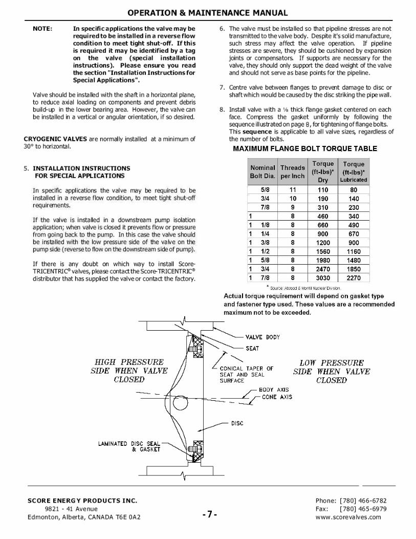
VALVE BODY
HIGH PRESSURE SIDE WHEN VALVE
CLOSED
SEAT
CONICAL TAPER OF SEAT AND SEAL SURFACE
LOW PRESSURE SIDE WHEN VALVE
CLOSED BODY AXIS
CONE AXIS
LAMINATED DISC SEAL & GASKET
OPERATION & MAINTENANCE MANUAL
NOTE: In specific applications the valve may be required to be installed in a reverse flow condition to meet tight shut-off. If this is required it may be identified by a tag on the valve (special installation instructions). Please ensure you read the section "Installation Instructions for Special Applications".
Valve should be installed with the shaft in a horizontal plane, to reduce axial loading on components and prevent debris build-up in the lower bearing area. However, the valve can be installed in a vertical or angular orientation, if so desired.
CRYOGENIC VALVES are normally installed at a minimum of 30° to horizontal.
5. INSTALLATION INSTRUCTIONS FOR SPECIAL APPLICATIONS
In specific applications the valve may be required to be installed in a reverse flow condition, to meet tight shut-off requirements.
If the valve is installed in a downstream pump isolation application; when valve is closed it prevents flow or pressure from going back to the pump. In this case the valve should be installed with the low pressure side of the valve on the pump side (reverse to flow on the downstream side of pump).
If there is any doubt on which way to install Score-TRICENTRIC'') valves, please contactthe Score-TRICENTRIC distributor that has supplied the valve or contact the factory.
6. The valve must be installed so that pipeline stresses are not transmitted to the valve body. Despite it's solid manufacture, such stress may affect the valve operation. If pipeline stresses are severe, they should be cushioned by expansion joints or compensators If supports are necessary for the valve, they.should only support the dead weight of the valve and should not serve as base points for the pipeline.
7. Centre valve between flanges to prevent damage to disc or shaft whic h would be caused by the disc striking the pipe wall.
8. Install valve with a Ye thick flange gasket centered on each face. Compress the gasket uniformly by following the sequence illustrated on page 8, for tighten i ng of flange bolts. This sequence is applicable to all valve sizes regardless of the number of bolts.
MAXIMUM FLANGE BOLT TORQUE TABLE
Nominal Bolt Dia.
Threads per Inch
Torque (ft-lbs)*
Dry
Torque (ft-lbs)*
Lubricated
5/8 11 110 80 3/4 10 190 140 7/8 9 310 230
1 8 460 340 1 1/8 8 660 490 1 1/4 8 900 670 1 3/8 8 1200 900 1 1/2 8 1560 1160 1 5/8 8 1980 1480 1 3/4 8 2470 1850 1 7/8 8 3030 2270
* Source: Atwood & Morrill Nuclear Division.
Actual torque requirement will depend on gasket type and fastener type used. These values are a recommended maximum not to be exceeded.
SCORE ENERGY PRODUCTS INC. 9821 - 41 Avenue
Edmonton, Alberta, CANADA T6E 0A2 - 7 -
Phone: [780] 466-6782 Fax: [780] 465-6979 www .sco reva Ives .com - 7 -
Position C
Position A
OPERATION & MAINTENANCE MANUAL
MAINTENANCE Refer to Parts Map for numbers in ( ).
General routine maintenance consists of tightening down the packing gland (38A) periodically to compensate for packing wear. Do not tighten the packing gland too severely as this will result in excessive gland pressure and reduce the packing service life. Gland studs are to be tightened in an opposing and proportionate manner until no leakage can be detected. For details on tightening live loaded packing, refer to section on "Changing the Packing".
More extensive maintenance such as disc seal, bearing, and packing replacement is described below.
Valve Removal
• Read the cautions section thoroughly! • Valve must be fully closed before removing it from the
pipeline.
CAUTION: Valves equipped with fail-open (air-to-close) actuators must be disconnected from the actuators and then closed, or there must be sufficient air pressure supplied to the actuator to close the valve while removing it from the pipeline. After valve removal, slowly relieve pressure in the actuator. Line pressure should be relieved before removal of actuator.
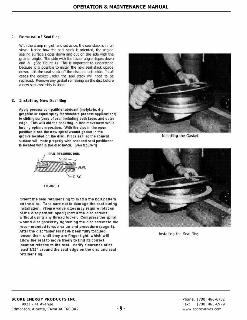
SEAL RING REPLACEMENT PROCEDURE
If the sealing system is suspected of unacceptable leakage, remove the valve from the line and the following simple checks can be made to determine if the disc seal must be replaced.
Check the appearance of the seal: • Are there nicks in the metal laminations? • Are the gasket laminations damaged, torn or broken? • Is the seal stack (the system of the metal gasket
laminations) bent or dented?
If any of the above conditions exist, SCORE recommends that the seal and gasket be replaced. If it has been determined that the seal stack must be replaced, the following steps must be followed. It is not necessary to completely disassemble a Score-T RICENTRIC7') valve to replace the disc seal.
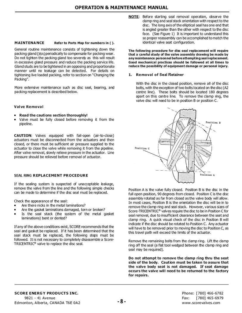
NOTE: Before starting seal removal operation, observe the clamp ring and seal stack orientation with respect to the disc. The long axis of the elliptical seal has one end that is angled greater than the other with respect to the disc face. (See Figure 1) It is important to understand this so proper reassembly can be accomplished to match the identical valve seat configuration.
The following procedure for disc seal replacement will require that a careful study of the valve assembly drawing be made by any maintenance person nel before attempting seal replacement. Good mechanical practices should be followed at all times to reduce the possibility of equipment damage or personal injury.
1. Removal of Seal Retainer
With the disc in the closed position, remove all of the disc bolts, with the exception of two bolts located on the disc (A2 centre line). These bolts should be located 180 degrees apart on this centre line. To remove the clamp ring, the valve disc will need to be in position B or position C.
Position A is the valve fully closed, Position B is the disc in the full open position, 90 degrees from closed. Position C is the disc assembly rotated as far from closed as the valve body will allow. In most cases, Position B is the orientation the disc will be in to remove the clamp ring and seal stack. However, various sizes of Score-TRICENTRIC valves require the disc to be in Position C for seal removal, due to insufficient clearance between the seat and clamp ring. A quick visual check of the disc in Position B will indicate if the disc should be rotated to Position C. Any actuator will have to be removed prior to moving the disc to Position C, as this travel path will exceed the limits of the actuator.
Remove the remaining bolts from the clamp ring. Lift the clamp ring off the seal (a flat tool wedged between the clamp ring and seal may be required).
Do not attempt to remove the clamp ring thru the seat side of the body. Caution must be taken to assure that the valve body seat is not damaged. If seat damage occurs the valve will need to be returned to the factory for repairs.
SCORE ENERGY PRODUCTS INC. 9821 - 11 Avenue
Edmonton, Alberta, CANADA T6E 0A2 - 8 -
Phone: [780] 466-6782
Fax: [780] 465-6979
www .scoreva Ives .com - 8 -
- 9 - - 9 -
- 10 - - 10 -
OPERATION & MAINTENANCE MANUAL
CHANGING THE PACKING.
Changing of the packing can be made without removing the valve actuator.
1. Depressurize the valve.
2. Remove all of the nuts from the studs holding the packing gland.
NOTE - If the valve includes live loaded packing option, then the Belleville washers, flat washers and spacer will also be removed.
3. Pull back the packing gland flange on the shaft. Pry off clip using a flat tool. Pull back packing tube. The packing is now accessible. (A flexible screw hook is needed to pull packing out of the bore, one at a time.)
NOTE - If the rings used are not split, the actuator will have to be removed from the valve.
4. Install new packing, one at a time, rotating the splices at 120° intervals. Use the packing gland to push each layer of packing evenly into bore. Once packing is installed (reverse of the above assembly). the gland can be tightened down with the nuts, using an alternate uniform tightening.
NOTE - If the valve includes live loaded packing option, then reinstall bottom flat washer, Belleville washers, spacer, then top flat washer before installing hex nut. Tighten down the nuts, using an alternate uniform tightening until resistance is felt from "bottoming" out on the spacers, do not tighten beyond "bottoming" out.
VALVE DISASSEMBLY
NOTE - If complete disassembly becomes necessary, replacement of all spare parts is recommended. The valve must be in the closed position during disassembly. See exploded view of valve for recommended spare parts and quantities on the parts map located on the back cover of this leaflet.
Special design - Due to the variety of options and special designs, the valve specific assembly drawing must be referenced for construction details. If no drawing is available, contact the factory for a copy.
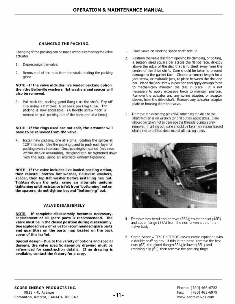
1. Place valve on working space shaft side up.
2. Restrain the valve disc from opening by clamping, or bolting, a suitably sized square bar across the flange face, directly above the edge of the disc that is furthest away from the centre of the drive shaft. Care should be taken to prevent damage to the gasket face. Choose a correct length for a jack screw, or hydraulic jack, to place between the disc and bar. Place the jack screw in position and apply enough force to mechanically maintain the disc in place. It is not necessary to apply excessive force to maintain position. Remove the actuator and any spline adaptor, or adaptor sleeve, from the drive shaft. Remove any actuator adaptor plate or housing from the valve.
3. Remove the centering pin (56A) attaching the disc to the shaft with an alien wrench (or drill out as applicable). Care should be taken not to dam age the threads during screw removal. If drilling out, care should be taken on steam-traced shafts not to drill too deep into s haft trac ing cavity.
4. Remove hex head cap screws (55A), cover gasket (438) and cover flange (37A) from the non-driven side of the valve body.
5. Some Score — TRICENTRIC® valves come equipped with a double stuffing box. If this is the case, remove the hex nuts (53), the gland flange (38A),follower(38L) and retaining clip (51), then remove the packing rings.
SCORE ENERGY PRODUCTS INC. 9821 - 41 Avenue
Edmonton, Alberta, CANADA T6E 0A2 - 11- (780) 466-6782
Fax: (780) 465-6979 www .sco re va Ives .com - 11 -
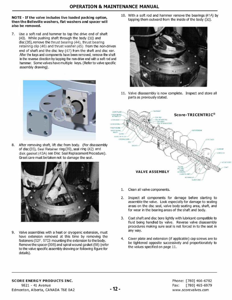
10. With a soft rod and hammer remove the bearings (41A) by tapping them outward from the inside of the body (30).
11. Valve disassembly is now complete. Inspect and store all parts as previously stated.
Score-TRICENTRIC®
HEAT EXTERSION
BORE SPACER
THRUST BEARING -
THRUST BEARING WASHER
BEARING
BEARING PROTECTOR
CENTERI. SCREW
s
-
c
466A 4 •41
-1LVE BODY
k*'N
SEAL RNG
...
-SEAL RETA NER R
DSFSALC G +71,1NG SCREWS
*410,
DISC KEY-,
GLAND NUT
GLAND STUD
ACTUATOR KEY
PACKING SPOT RI.
PACKING DIEFORM RI.
GLAND FOLL OWER
RETAINNG CLIP
GLAND FLANGE
SHAFT
COVER FLA.E
THRUST BEAR. RETAINER CLIP
COVER GASKET
COVER SCREWS -
VALVE ASSEMBLY
1. Clean all valve components.
2. Inspect all components for damage before starting to assemble the valve. Look especially for damage to sealing areas on the disc seal, valve body seating area, shaft, and for wear in the bearing areas of the shaft and body.
3. Coat shaft and disc bore lightly with lubricant compatible to fluid being handled by valve. Reverse valve disassembly procedures making sure seal is not forced in to the seat in any way.
4. Cover plate and extension (if applicable) cap screws are to be tightened opposite successively and proportionately to the values specified on page 11.
OPERATION & MAINTENANCE MANUAL
NOTE - If the valve includes live loaded packing option, then the Belleville washers, flat washers and spacer will also be removed.
7. Use a soft rod and hammer to tap the drive end of shaft (40). While pushing shaft through the body (30) and disc (35), remove the thrust bearing (44), thrust bearing retaining clip (46) and thrust washer (45) from the non-driven end of shaft and the disc key (47) from the shalt and disc ear. After the keys and components have been removed, remove the shaft in the reverse direction by tapping the non-drive end with a soft rod and hammer. Some valves have multiple keys. (Refer to valve specific assembly drawing).
8. After removing shaft, lift disc from body. (For disassembly of disc (35), Seal Retainer ring (36), seal ring (42) and disk gasket (43A) see Disc Seal Replacement Procedure). Great care must betaken not to damage the seal.
9. Valve assemblies with a heat or cryogenic extension, must have extension removed at this time by removing the fasteners (52F, 57D) mounting the extension to the body. Remove the spacer (39B) and spiral wound gasket (58) (refer to the valve specific assembly drawing or following figure for details).
SCORE ENERGY PRODUCTS INC. 9821 - 41 Avenue
Edmonton, Alberta, CANADA T6E 0A2 - 12 -
Phone: [780] 466-6782 Fax: [780] 465-6979 www . scoreva Ives .com - 12 -
OPERATION & MAINTENANCE MANUAL
COVER GASKET
COVER SCREWS
THRUST BEARING
THRUST BEARING RETAINER CUP
VALVE BODY
SEAL RING
SEAL RETAINER RING
DISC GASKET
SEAL RETAINING SCREWS
THRUST BEARING WASHER
BEARING GLAND NUT
GLAND STUD BEARING PROTECTOR
8. When the factory assembles the valve and actuator or gear operator, as required, this information will ensure the valve will operate properly.
9. To ensure proper shut-off specification is obtained the factory always completes the seat leakage test after the actuators or gear operatorsa re installed. When testing the valve it is important to know how the valve is going to be installed and the control conditions it is required to meet.
10. If actuators are being supplied by another vendor it is very important the factory has contact w ith that vendor to ensure proper sizing and adjustments are made and a seat leakage test should then be done to ensure the valve operates to design specifications.
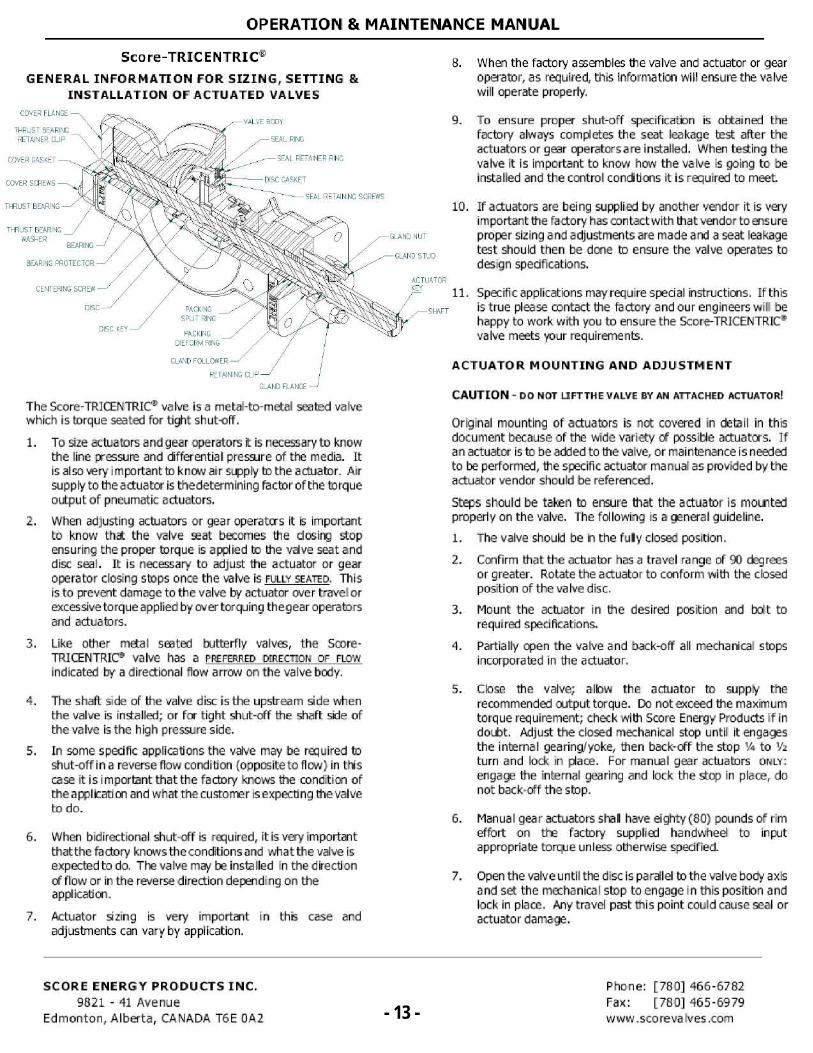
Score-TRICENTRIC
GENERAL INFORMATION FOR SIZING, SETTING & INSTALLATION OF ACTUATED VALVES
COVER FLANGE
CENTERING SCREW ACTUATOR KEY
11.
DISC PACKING SPUT RING
SHAFT
DISC KEY PACKING
DIEFORM RING
Specific applications may require special instructions. If this is true please contact the factory and our engineers will be happy to work with you to ensure the Score-TRICENTRIC® valve meets your requirements.
GLAND FOLLOWER
RETAINING CLIP
GLAND FLANGE
The 5core-TRICENTRIC® valve is a metal-to-metal seated valve which is torque seated for tight shut-off.
1. To size actuators and gear operators it is necessary to know the line pressure and differential pressure of the media. It is also very important to know air supply to the actuator. Air supply to the actuator is thedetermining factor of the torque output of pneumatic actuators.
2. When adjusting actuators or gear operatcrs it is important to know that the valve seat becomes the closing stop ensuring the proper torque is applied to the valve seat and disc seal. It is necessary to adjust the actuator or gear operator closing stops once the valve is FULLY SEATED. This is to prevent damage to the valve by actuator over travel or exces sive to rque ap plied by aver torquing thegear operators and actuators.
3. Like other metal seated butterfly valves, the Score-TRICENTRIC® valve has a PREFERRED DIRECTION OF FLOW
indicated by a directional flow arrow on the valve body.
4. The shaft side of the valve disc is the upstream side when the valve is installed; or for tight shut-off the shaft side of the valve is the high pressure side.
5. In some specific applications the valve may be required to shut-off in a reverse flow condition (opposite to flow) in thi s case it is important that the factory knows the condition of the a pplication and what the customer I s expect ng the valve to do.
6. When bidirectional shut-off is required, it is very important that the factory knows the conditions and what the valve is expected to do. The valve may be insta lied in the direction of flow or in the reverse direction depending on the application.
7. Actuator sizing is very important in this case and adjustments can vary by application.
ACTUATOR MOUNTING AND ADJUSTMENT
CAUTION - DO NOT LIFTTHE VALVE BY AN ATTACHED ACTUATOR!.
Original mounting of actuators is not covered in detail in this document because of the wide variety of possible actuators. If a n actuator is to be added to the valve, or maintenance i s needed to be performed, the specific actuator manual as provided by the actuator vendor should be referenced.
Steps should be taken to ensure that the actuator is mounted properly on the valve. The following is a general guideline.
1. The valve should be in the fully closed position.
2. Confirm that the actuator has a travel range of 90 degrees or greater. Rotate the actuator to conform with the closed position of the valve disc.
3. Mount the actuator in the desired position and bolt to required specifications.
4. Partially open the valve and back-off all mechanical stops incorporated in the actuator.
5. Close the valve; allow the actuator to supply the recommended output torque. Do not exceed the maximum torque requirement; check with Score Energy Products if in doubt. Adjust the closed mechanical stop until it engages the internal gearing/yoke, then back-off the stop Y4 to Y2
turn and lock in place. For manual gear actuators owe: engage the internal gearing and lock the stop in place, do not back-off the stop.
6. Manual gear actuators shall have eighty (80) pounds of rim effort on the factory supplied handwheel to input appropriate torque unless otherwise specified.
7. Open the valve until the disc is pa rale! to the valve body axis and set the mechanical stop to engage in this position and lock in place. Any travel past this point could cause seal or actuator damage.
SCORE ENERGY PRODUCTS INC. 9821 - 41 Avenue
Edmonton, Alberta, CANADA T6 E 0A2 - 13-
[780] 466-6782
Fax: [780] 465-6979
www.sco revs Ives .com - 13 -
OPERATION & MAINTENANCE MANUAL
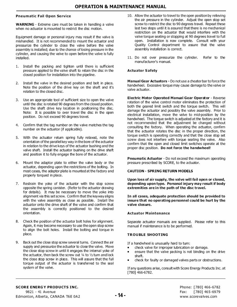
Pneumatic Fail Open Service
WARNING - Extreme care must be taken in handling a valve when no actuator is mounted to restrict the disc motion.
Equipment damage or personal injury may result if the valve is mishandled. It is not recommended to mount the actuator and pressurize the cylinder to close the valve before the valve assembly is installed; due to the chance of losing pressure in the cylinder, and causing the valve to open before the valve is fully installed.
1. Install the packing and tighten until there is sufficient pressure applied to the valve shaft to rain the disc in the dosed position for installation into the pipeline.
2. Install the valve in the desired position and bolt in place. Note the position of the drive key on the shaft and it's relation to the closed disc.
3. Use an appropriate tool of sufficient size to open the valve until the disc is rotated 90 degrees from the closed position. Use the shaft drive key location in positioning the disc. Note: It is possible to over travel the disc in the open position. Do not exceed 90 degrees travel.
4. Confirm that the tag number on the valve matches the tag number on the actuator (if applicable).
5. With the actuator return spring fully relaxed, note the orientation of the parallel key way in the bore of the actuator in relation to the drive keys of the actuator bushing and the valve shaft Install the actuator bushing on the drive shaft and position it to fully engage the bore of the actuator.
6. Mount the adaptor plate to either the valve body or the actuator, depending upon the restrictions of the bolting. In most cases, the adaptor plate is mounted at the factory and properly torqued in place.
7. Restrain the yoke of the actuator with the stop screw opposite the spring canister. (Refer to the actuator drawing for details). It may be necessary to move the yoke into alignment via this setscrew. Confirm that the keyway aligns with the valve assembly as dose as possible. Install the actuator onto the drive shaft of the valve and confirm that the assembly is correctly positioned to the desired orientation.
8. Check the position of the actuator bolt holes for alignment. Again, it may become necessary to use the open stop screw to align the bolt holes. Install the bolting and torque in place.
9. Back out the close stop screw several turns. Connect the air supply and pressurize the actuator to dose the valve. Move the close stop screw in until it engages the internal yoke of the actuator, then back the screw out 1/4 to 1/2 turn and lock the dose stop screw in place. This will assure that the full torque output of the actuator is transferred to the seal system of the valve.
10. Allow the actuator to travel to the open position by relieving the air pressure in the cylinder. Adjust the open stop set screw to restrict the disc to 90 degrees travel. Repeat these last two steps until it is assured that there is no mechanical restriction on the actuator that would interfere with the valve torque seating or stopping at 90 degrees travel to full open. Installation is now complete. Consult with your Quality Control department to assure that the valve assembly installation is correct.
11. Do not over pressurize the cylinder. Refer to the manufacturer's manual.
Actuator Safety
Manual Gear Actuators - Do not use a cheater bar to force the handwheel. Excessive torque may cause damage to the valve or valve actuator.
Electric Motor Operated Manual Gear Operator - Reverse rotation of the valve control motor eliminates the protection of both the geared limit switch and the torque switch. This will damage the actuator and possibly the valve assembly. Prior to electrical installation, move the valve to mid-position by the handwheel. The torque switch is adjusted at the factory and it is not recommended that the adjustment be changed without consulting the factory. When operating the actuator, confirm that the actuator rotates the disc in the proper direction, the torque switch is operating correctly and that the close stop set screw does not interfere with torque seating the valve. Also confirm that the open and closed limit switches operate at the proper disc position. Do not force the handwheel!
Pneumatic Actuator - Do not exceed the maximum operating pressure prescribed by SCORE, to the actuator.
CAUTION - SPRING RETURN MODELS
Upon loss of air supply, the valve will fail open or closed, depending upon type. Personal injury may result if body extremities are in the path of the disc travel.
In all cases, adequate protection should be provided to insure that no operating personnel could be hurt by the valve closure.
Actuator Maintenance
Separate actuator manuals are supplied. Please refer to this manual if maintenance is to be performed.
TROUBLE SHOOTING
If a handwheel is unusually hard to turn: ■ check valve for improper lubrication or damage. ■ ensure that the valve packing is not binding on the drive
shaft. ■ check for faulty or damaged valves parts or obstructions.
If any questions arise, consult with Score Energy Products Inc. at [780] 466-6782.
SCORE ENERGY PRODUCTS INC. 9821 - 41 Avenue
Edmonton, Alberta, CANADA T6E 0A2 - 14-
[780] 466-6782 Fax: [780) 465-6979 www .sco re va Ives .com - 14 -
OPERATION & MAINTENANCE MANUAL
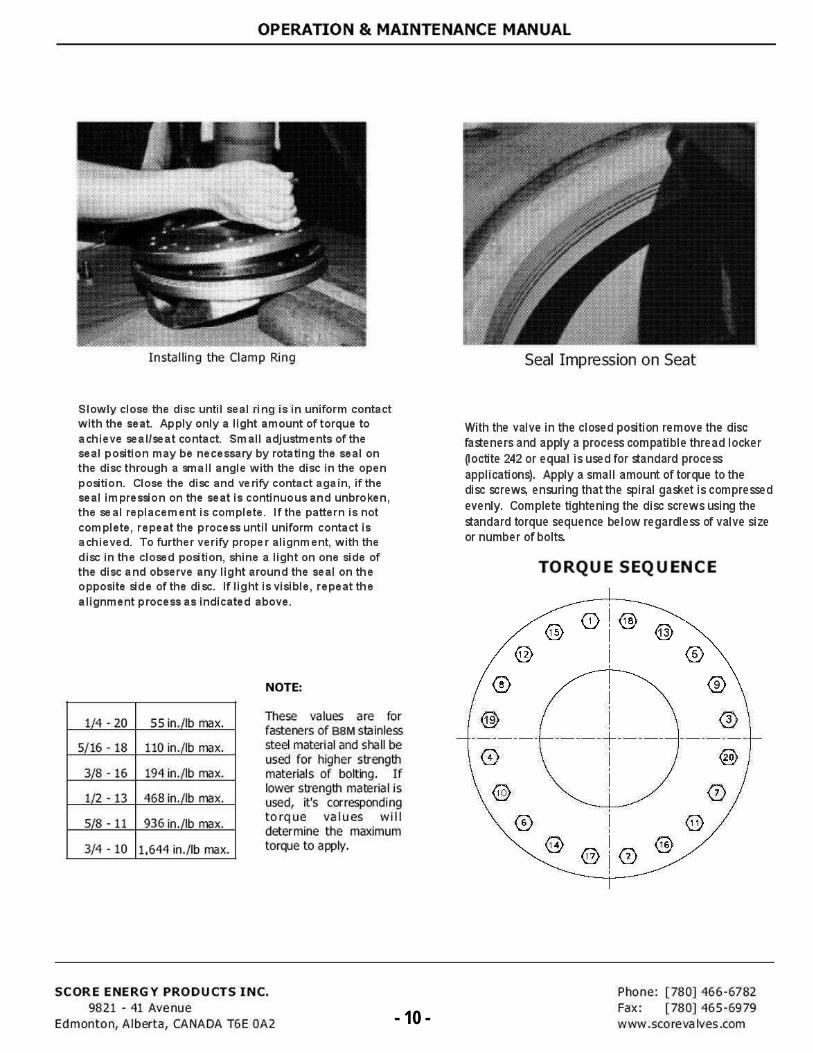
PROCEDURE FOR TORQUING THREADED FASTENERS
E This procedures applies to valves manufactured by Score Energy Products at its Edmonton, Alberta plant.
E This procedure shall be used to verify proper torque application to threaded fasteners used in assembly of valves.
Equipment Required - Torque wrenches. These may be dial indicator type or dick-type and calibrated p& prescribed procedure.
PROCEDURE
Assembly Assemble threaded fasteners to mating parts as indicated on theassembly drawing aid run down to finger tightness. Using a torque wrench apply approximately 75% of the torque specified on the torque chart, in a uniform manner (criss-cross rather than in adjacent sequence), then the balance of the torque in two or three equal increments, also in a uniform manner, to within ± 10 in.lb.
Testing Using a torque wrench in a uniform manner (criss-cross) apply torque to the fastener, within th 5%. Hydro test after completion of torque sequence.
Final Inspection Using a torque wrench in a uniform manner (criss-cross) verify torque requirements within th 5% of tabulated values.
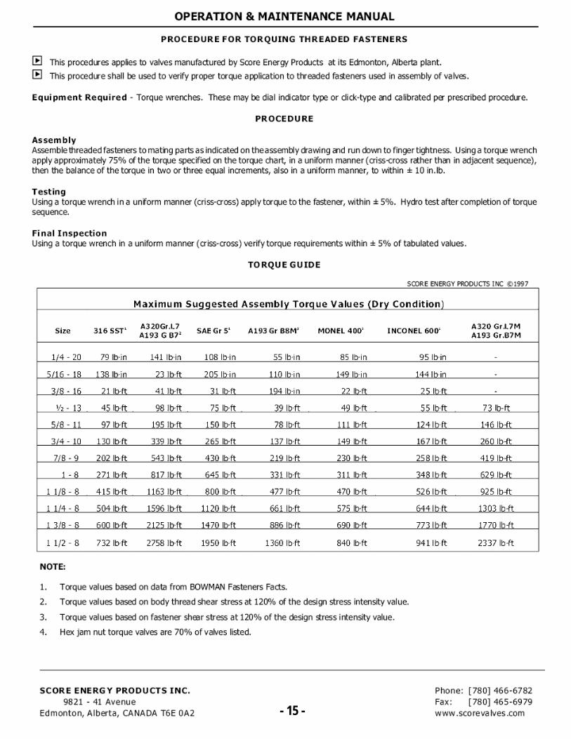
TORQUE GUIDE
SCORE ENERGY PRODUCTS INC ©1997
Maximum Suggested Assembly Torque Values (Dry Condition)
Size 316 SST' A320Gr.L7 11.193 G B72 SAE Gr 5' A193 Gr B8M3 MONEL 400' INCONEL 6-00' A320 Gr.L7M
A193 Gr.B7M
1/4 - 20 79 Ilyin 141 lb•in 108 lb•in 55 Ilyin 85 lb-in 95 bin -
5/16 - 18 138 lbin 23 lbft 205 lb-in 110 lb-in 149 lb-in 144 Ibin
3/8 - 16 21 lb-ft 41 lb-ft 31 lb-ft 194 lb-in 22 lb-ft 25 lb-ft -
1/z - 13 45 lb-ft 98 lb-ft 75 lb-ft 39 lb-ft 49 lb-ft 55 Ibtt 73 lb-ft
5/8 - 11 97 'bit 195 lb•ft 150 lb•ft 78 !bit 111 lb•ft 124 !bit 146 lb-ft
3/4 - 10 130 Iblt 339 lb•ft 265 lb•ft 137 lb•ft 149 tit 167 lb.ft 260 lb-ft
7/8 - 9 202 lb.ft 543 lb.ft 430 lb.ft 219 lb.ft 230 lb.ft 258 ILIA 419 lb-ft
1 - 8 271 lb-ft 817 lb-ft 645 lb-ft 331 lb•ft 311 lb.ft 348 lb-ft 629 lb-ft
1 1/$ - 8 415 Ibit 1163 lb-ft $00 lb-ft 477 lb-ft 470 lb-ft 526 Ibtt 925 lb-ft
1 1/4 - 8 504113.ft 1596113.ft 1120 lb•ft 661 Ilyft 575113.ft 644 !bit 1303 lb-ft
1 3/8 - 8 600 lb-ft 2125 lb•ft 1470 lb-ft 886 lb•ft 690 lb•ft 773 lb-ft 1770 lb-ft
1 1/2 - 8 732 'bit 2758 lb .ft 1950 lb-ft 1360 lb-ft 840 lb•ft 9411b.ft 2337 lb-ft
NOTE:
1. Torque values based on data from BOWMAN Fasteners Facts.
2. Torque values based on body thread shear stress at 120% of the design stress intensity value.
3. Torque values based on fastener sheer stress at 120% of the design stress intensity value.
4. Hex jam nut torque valves are 70% of valves listed.
SCORE ENERGY PRODUCTS INC. 9821 - 41 Avenue
Edmonton, Alberta, CANADA T6E 0A2 - 15 -
Phone: [780] 466-6782 Fax: [780] 465-6979 www .sco re va Ives .com - 15 -
VALVE
SIZE
VALVE
SIZE
QTY. BOLTING DATA QTY. BOLTING DATA QTY. BOLTING DATA QTY.BOLTING
DATA
3 85/8-11 UNC
x 2" LONG- - 3 12
3/4-10 UNC
x 2 1/4" LONG4
3/4-10 UNC
x 2" LONG
4 165/8-11 UNC
x 2 1/8" LONG- - 4 16
3/4-10 UNC
x 2 1/2" LONG- -
6 163/4-10 UNC
x 2 1/4" LONG- - 6 20
3/4-10 UNC
x 2 1/2" LONG4
3/4-10 UNC
x 2 7/16" LONG
8 163/4-10 UNC
x 2 3/8" LONG- - 8 24
7/8-9 UNC
x 2 7/8" LONG- -
10 247/8-9 UNC
x 2 1/2" LONG- - 10 28
1-8 UNC
x 3 1/4" LONG4
1-8 UNC
x 3" LONG
12 247/8-9 UNC
x 2 3/4" LONG- - 12 28
1 1/8-8 UN
x 3 1/2" LONG4
1 1/8-8 UN
x 3 7/16" LONG
14 241-8 UNC
x 3" LONG- - 14 32
1 1/8-8 UN
x 4" LONG8
1 1/8-8 UN
x 3 1/2" LONG
16 321-8 UNC
x 2 7/8" LONG- - 16 32
1 1/4-8 UN
x 4" LONG8
1 1/4-8 UN
x 3 11/16"
18 281 1/8-8 UN
x 3 1/2" LONG4
1 1/8-8 UN
x 3 1/8" LONG18 48
1 1/4-8 UN
x 4" LONG- -
20 361 1/8-8 UN
x 3 3/8" LONG4
1 1/8-8 UN
x 3" LONG20 40
1 1/4-8 UN
x 4 1/2" LONG8
1 1/4-8 UN
x 4 1/8" LONG
24 401 1/4-8 UN
x 3 3/4" LONG- - 24 40
1 1/2-8 UN
x 4 3/4" LONG8
1 1/2-8 UN
x 4 5/16" LONG
30 561 1/4-8 UN
x 4 3/4" LONG- - 30 48
1 3/4-8 UN
x 6 1/2" LONG8
1 3/4-8 UN
x 6" LONG
36 641 1/2-8 UN
x 5 5/8" LONG- - 36 64
2-8 UN
x 6 7/8" LONG- -
42 721 1/2-8 UN
x 6" LONG- - 42 64
1 5/8-8 UN
x 7" LONG- -
48 801 1/2-8 UN
x 6 1/4" LONG8
1 1/2-8 UN
x 6" LONG
54 881 3/4-8 UN
x 7" LONG- -
60 1041 3/4-8 UN
x 7 1/2" LONG- -
64 1041 1/4-8 UN
x 6" LONG- -
72 1161 3/4-8 UN
x 6" LONG4
1 3/4-8 UN
x 5 1/2" LONG
VALVE
SIZE
QTY. BOLTING DATA QTY. BOLTING DATA
- - - - -
- - - - -
6 201-8 UNC
x 3 1/2" LONG4
1-8 UNC
x 3 3/16" LONGNOTES:
8 201 1/8-8 UN
x 4 3/16" LONG4
1 1/8-8 UN
x 3 5/8" LONG
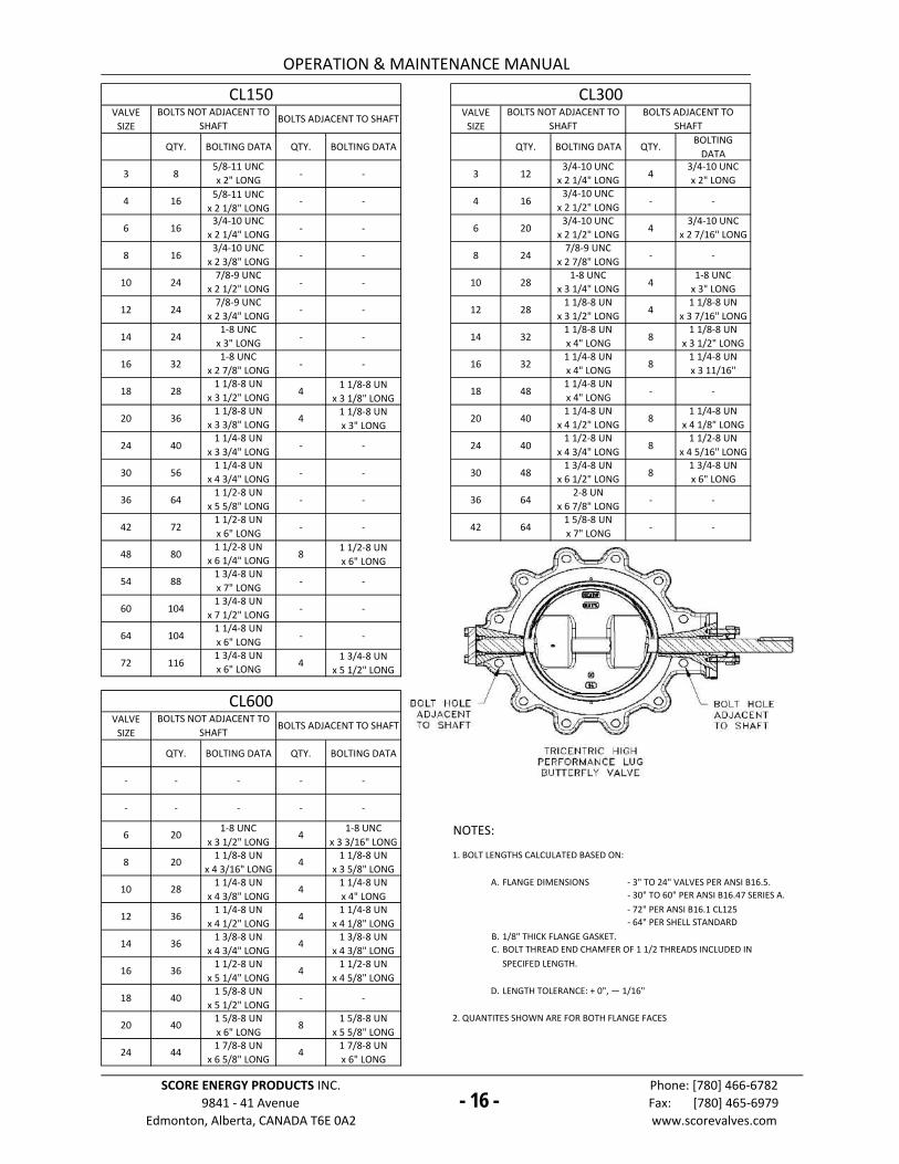
1. BOLT LENGTHS CALCULATED BASED ON:
10 281 1/4-8 UN
x 4 3/8" LONG4
1 1/4-8 UN
x 4" LONG
A.
12 361 1/4-8 UN
x 4 1/2" LONG4
1 1/4-8 UN
x 4 1/8" LONG
14 361 3/8-8 UN
x 4 3/4" LONG4
1 3/8-8 UN
x 4 3/8" LONG
B.
C.
16 361 1/2-8 UN
x 5 1/4" LONG4
1 1/2-8 UN
x 4 5/8" LONG
18 401 5/8-8 UN
x 5 1/2" LONG- -
D.
20 401 5/8-8 UN
x 6" LONG8
1 5/8-8 UN
x 5 5/8" LONG
24 441 7/8-8 UN
x 6 5/8" LONG4
1 7/8-8 UN
x 6" LONG
-16-
Phone: [780] 466-6782
Fax: [780] 465-6979
www.scorevalves.com
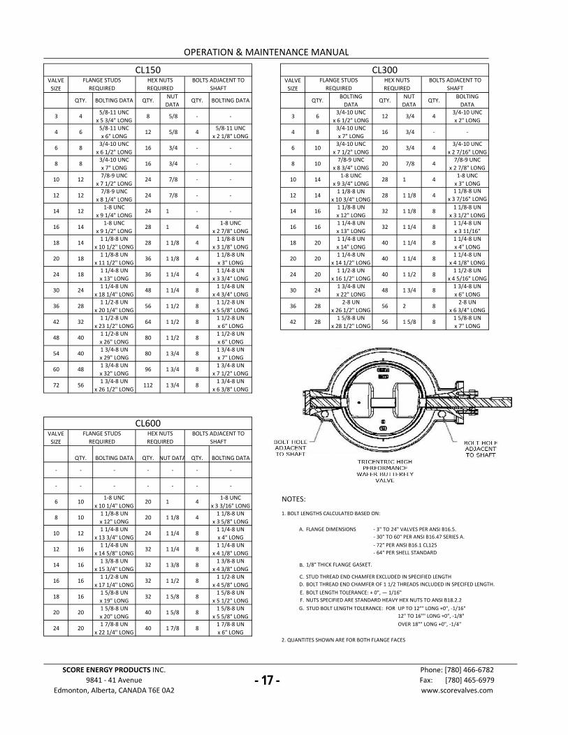
SPECIFED LENGTH.
LENGTH TOLERANCE: + 0", — 1/16"
1/8" THICK FLANGE GASKET.
BOLT THREAD END CHAMFER OF 1 1/2 THREADS INCLUDED IN
SCORE ENERGY PRODUCTS INC.
9841 - 41 Avenue
Edmonton, Alberta, CANADA T6E 0A2
- 3" TO 24" VALVES PER ANSI B16.5.
- 30" TO 60" PER ANSI B16.47 SERIES A.
FLANGE DIMENSIONS
- 72" PER ANSI B16.1 CL125
- 64" PER SHELL STANDARD
2. QUANTITES SHOWN ARE FOR BOTH FLANGE FACES
OPERATION & MAINTENANCE MANUAL
CL600BOLTS NOT ADJACENT TO
SHAFTBOLTS ADJACENT TO SHAFT
CL150 CL300BOLTS NOT ADJACENT TO
SHAFTBOLTS ADJACENT TO SHAFT
BOLTS NOT ADJACENT TO
SHAFT
BOLTS ADJACENT TO
SHAFT
- 16 -
VALVE
SIZE
VALVE
SIZE
QTY. BOLTING DATA QTY.NUT
DATAQTY. BOLTING DATA QTY.
BOLTING
DATAQTY.
NUT
DATAQTY.
BOLTING
DATA
3 45/8-11 UNC
x 5 3/4" LONG8 5/8 - - 3 6
3/4-10 UNC
x 6 1/2" LONG12 3/4 4
3/4-10 UNC
x 2" LONG
4 65/8-11 UNC
x 6" LONG12 5/8 4
5/8-11 UNC
x 2 1/8" LONG4 8
3/4-10 UNC
x 7" LONG16 3/4 - -
6 83/4-10 UNC
x 6 1/2" LONG16 3/4 - - 6 10
3/4-10 UNC
x 7 1/2" LONG20 3/4 4
3/4-10 UNC
x 2 7/16" LONG
8 83/4-10 UNC
x 7" LONG16 3/4 - - 8 10
7/8-9 UNC
x 8 3/4" LONG20 7/8 4
7/8-9 UNC
x 2 7/8" LONG
10 127/8-9 UNC
x 7 1/2" LONG24 7/8 - - 10 14
1-8 UNC
x 9 3/4" LONG28 1 4
1-8 UNC
x 3" LONG
12 127/8-9 UNC
x 8 1/4" LONG24 7/8 - - 12 14
1 1/8-8 UN
x 10 3/4" LONG28 1 1/8 4
1 1/8-8 UN
x 3 7/16" LONG
14 121-8 UNC
x 9 1/4" LONG24 1 - - 14 16
1 1/8-8 UN
x 12" LONG32 1 1/8 8
1 1/8-8 UN
x 3 1/2" LONG
16 141-8 UNC
x 9 1/2" LONG28 1 4
1-8 UNC
x 2 7/8" LONG16 16
1 1/4-8 UN
x 13" LONG32 1 1/4 8
1 1/4-8 UN
x 3 11/16"
18 141 1/8-8 UN
x 10 1/2" LONG28 1 1/8 4
1 1/8-8 UN
x 3 1/8" LONG18 20
1 1/4-8 UN
x 14" LONG40 1 1/4 8
1 1/4-8 UN
x 4" LONG
20 181 1/8-8 UN
x 11 1/2" LONG36 1 1/8 4
1 1/8-8 UN
x 3" LONG20 20
1 1/4-8 UN
x 14 1/2" LONG40 1 1/4 8
1 1/4-8 UN
x 4 1/8" LONG
24 181 1/4-8 UN
x 13" LONG36 1 1/4 4
1 1/4-8 UN
x 3 3/4" LONG24 20
1 1/2-8 UN
x 16 1/2" LONG40 1 1/2 8
1 1/2-8 UN
x 4 5/16" LONG
30 241 1/4-8 UN
x 18 1/4" LONG48 1 1/4 8
1 1/4-8 UN
x 4 3/4" LONG30 24
1 3/4-8 UN
x 22" LONG48 1 3/4 8
1 3/4-8 UN
x 6" LONG
36 281 1/2-8 UN
x 20 1/4" LONG56 1 1/2 8
1 1/2-8 UN
x 5 5/8" LONG36 28
2-8 UN
x 26 1/2" LONG56 2 8
2-8 UN
x 6 3/4" LONG
42 321 1/2-8 UN
x 23 1/2" LONG64 1 1/2 8
1 1/2-8 UN
x 6" LONG42 28
1 5/8-8 UN
x 28 1/2" LONG56 1 5/8 8
1 5/8-8 UN
x 7" LONG
48 401 1/2-8 UN
x 26" LONG80 1 1/2 8
1 1/2-8 UN
x 6" LONG
54 401 3/4-8 UN
x 29" LONG80 1 3/4 8
1 3/4-8 UN
x 7" LONG
60 481 3/4-8 UN
x 32" LONG96 1 3/4 8
1 3/4-8 UN
x 7 1/2" LONG
72 561 3/4-8 UN
x 26 1/2" LONG112 1 3/4 8
1 3/4-8 UN
x 6 3/8" LONG
VALVE
SIZE
QTY. BOLTING DATA QTY. NUT DATA QTY. BOLTING DATA
- - - - - - -
- - - - - - -
6 101-8 UNC
x 10 1/4" LONG20 1 4
1-8 UNC
x 3 3/16" LONGNOTES:
8 101 1/8-8 UN
x 12" LONG20 1 1/8 4
1 1/8-8 UN
x 3 5/8" LONG
1. BOLT LENGTHS CALCULATED BASED ON:
10 121 1/4-8 UN
x 13 3/4" LONG24 1 1/4 8
1 1/4-8 UN
x 4" LONG
A.
12 161 1/4-8 UN
x 14 5/8" LONG32 1 1/4 8
1 1/4-8 UN
x 4 1/8" LONG
14 161 3/8-8 UN
x 15 3/4" LONG32 1 3/8 8
1 3/8-8 UN
x 4 3/8" LONGB.
16 161 1/2-8 UN
x 17 1/4" LONG32 1 1/2 8
1 1/2-8 UN
x 4 5/8" LONG
C.
D.
18 161 5/8-8 UN
x 19" LONG32 1 5/8 8
1 5/8-8 UN
x 5 1/2" LONG
E.
F.
20 201 5/8-8 UN
x 20" LONG40 1 5/8 8
1 5/8-8 UN
x 5 5/8" LONG
G.
24 201 7/8-8 UN
x 22 1/4" LONG40 1 7/8 8
1 7/8-8 UN
x 6" LONG
-17-
OPERATION & MAINTENANCE MANUAL
CL600FLANGE STUDS
REQUIRED
HEX NUTS
REQUIRED
BOLTS ADJACENT TO
SHAFT
CL150 CL300FLANGE STUDS
REQUIRED
HEX NUTS
REQUIRED
BOLTS ADJACENT TO
SHAFT
FLANGE STUDS
REQUIRED
HEX NUTS
REQUIRED
BOLTS ADJACENT TO
SHAFT
FLANGE DIMENSIONS - 3" TO 24" VALVES PER ANSI B16.5.
- 30" TO 60" PER ANSI B16.47 SERIES A.
1/8" THICK FLANGE GASKET.
SCORE ENERGY PRODUCTS INC.
9841 - 41 Avenue
Edmonton, Alberta, CANADA T6E 0A2
Phone: [780] 466-6782
Fax: [780] 465-6979
www.scorevalves.com
2. QUANTITES SHOWN ARE FOR BOTH FLANGE FACES
STUD THREAD END CHAMFER EXCLUDED IN SPECIFIED LENGTH
BOLT THREAD END CHAMFER OF 1 1/2 THREADS INCLUDED IN SPECIFED LENGTH.
BOLT LENGTH TOLERANCE: + 0", — 1/16"
NUTS SPECIFIED ARE STANDARD HEAVY HEX NUTS TO ANSI B18.2.2
OVER 18"" LONG +0", -1/4"
STUD BOLT LENGTH TOLERANCE: FOR UP TO 12"" LONG +0", -1/16"
12" TO 16"" LONG +0", -1/8"
- 72" PER ANSI B16.1 CL125
- 64" PER SHELL STANDARD
- 17 -
VALVE
SIZE
VALVE
SIZE
QTY. STUD DATA QTY.NUT
DATAQTY. BOLTING DATA QTY. STUD DATA QTY.
NUT
DATAQTY. BOLTING DATA
3 85/8-11 UNC
x 3 3/4" LONG16 5/8 - - 3 8
3/4-10 UNC
x 4 1/4" LONG16 3/4 8
3/4-10 UNC
x 2 1/4" LONG
4 85/8-11 UNC
x 3 3/4" LONG16 5/8 8
5/8-11 UNC
x 2" LONG4 8
3/4-10 UNC
x 4 1/2" LONG16 3/4 8
3/4-10 UNC
x 2 3/8" LONG
6 83/4-10 UNC
x 4" LONG16 3/4 8
3/4-10 UNC
x 2 3/16" LONG6 16
3/4-10 UNC
x 5" LONG32 3/4 8
3/4-10 UNC
x 2 1/2" LONG
8 83/4-10 UNC
x 4 1/4" LONG16 3/4 8
3/4-10 UNC
x 2 1/4" LONG8 16
7/8-9 UNC
x 5 1/2" LONG32 7/8 8
7/8-9 UNC
x 2 7/8" LONG
10 167/8-9 UNC
x 4 3/4" LONG32 7/8 8
7/8-9 UNC
x 2 7/16" LONG10 24
1-8 UNC
x 6 1/4" LONG48 1 8
1-8 UNC
x 3 3/8" LONG
12 167/8-9 UNC
x 4 3/4" LONG32 7/8 8
7/8-9 UNC
x 2 1/2" LONG12 24
1 1/8-8 UN
x 6 3/4" LONG48 1 1/8 8
1 1/8-8 UN
x 3 5/8" LONG
14 161-8 UNC
x 5 1/4" LONG32 1 8
1-8 UNC
x 2 3/4" LONG14 32
1 1/8-8 UN
x 7" LONG64 1 1/8 8
1 1/8-8 UN
x 3 7/8" LONG
16 241-8 UNC
x 5 1/2" LONG48 1 8
1-8 UNC
x 2 7/8" LONG16 32
1 1/4-8 UN
x 7 1/2" LONG64 1 1/4 8
1 1/4-8 UN
x 4" LONG
18 241 1/8-8 UN
x 6" LONG48 1 1/8 8
1 1/8-8 UN
x 3" LONG18 40
1 1/4-8 UN
x 7 3/4" LONG80 1 1/4 8
1 1/4-8 UN
x 4 3/8" LONG
20 321 1/8-8 UN
x 6 1/4" LONG64 1 1/8 8
1 1/8-8 UN
x 3 3/16" LONG20 40
1 1/4-8 UN
x 8 1/4" LONG80 1 1/4 8
1 1/4-8 UN
x 4 3/8" LONG
24 321 1/4-8 UN
x 7" LONG64 1 1/4 8
1 1/4-8 UN
x 3 1/2" LONG24 40
1 1/2-8 UN
x 9 1/4" LONG80 1 1/2 8
1 1/2-8 UN
x 5" LONG
30 481 1/4-8 UN
x 9 1/4" LONG96 1 1/4 8
1 1/4-8 UN
x 4 3/4" LONG30 48
1 3/4-8 UN
x 12" LONG96 1 3/4 8
1 3/4-8 UN
x 6" LONG
36 561 1/2-8 UN
x 11" LONG112 1 1/2 8
1 1/2-8 UN
x 5 3/4" LONG36 56
2-8 UN
x 13 1/2" LONG112 2 8
2-8 UN
x 6 7/8" LONG
42 641 1/2-8 UN
x 11 1/2" LONG128 1 1/2 8
1 1/2-8 UN
x 5 3/4" LONG42 56
1 5/8-8 UN
x 14" LONG112 1 5/8 8
1 5/8-8 UN
x 7" LONG
48 801 1/2-8 UN
x 12 1/2" LONG160 1 1/2 8
1 1/2-8 UN
x 6 1/4" LONG
54 801 3/4-8 UN
x 14" LONG160 1 3/4 8
1 3/4-8 UN
x 7" LONG
60 881 3/4-8 UN
x 15" LONG176 1 3/4 16
1 3/4-8 UN
x 8 1/8" LONG
72 1121 3/4-8 UN
x 15" LONG224 1 3/4 8
1 3/4-8 UN
x 6 15/16"LONG
VALVE
SIZE
QTY. STUD DATA QTY.NUT
DATAQTY. BOLTING DATA
- - - - - - -
- - - - - - -
6 161-8 UNC
x 6 3/4" LONG32 1 8
1-8 UNC
x 3 1/2" LONGNOTES:
8 161 1/8-8 UN
x 7 1/2" LONG32 1 1/8 8
1 1/8-8 UN
x 4" LONG
1. BOLT LENGTHS CALCULATED BASED ON:
10 241 1/4-8 UN
x 8 1/2" LONG48 1 1/4 8
1 1/4-8 UN
x 4 1/2" LONG
A.
12 321 1/4-8 UN
x 8 3/4" LONG64 1 1/4 8
1 1/4-8 UN
x 4 5/8" LONG B.
14 321 3/8-8 UN
x 9 1/4" LONG64 1 3/8 8
1 3/8-8 UN
x 4 7/8" LONG
C.
D.
16 321 1/2-8 UN
x 10" LONG64 1 1/2 8
1 1/2-8 UN
x 5 1/4" LONG
E.
F.
18 321 5/8-8 UN
x 10 3/4" LONG64 1 5/8 8
1 5/8-8 UN
x 5 1/2" LONG
G.
20 401 5/8-8 UN
x 11 1/4" LONG80 1 5/8 8
1 5/8-8 UN
x 6" LONG
24 401 7/8-8 UN
x 13" LONG80 1 7/8 8
1 7/8-8 UN
x 6 1/2" LONG
-18-
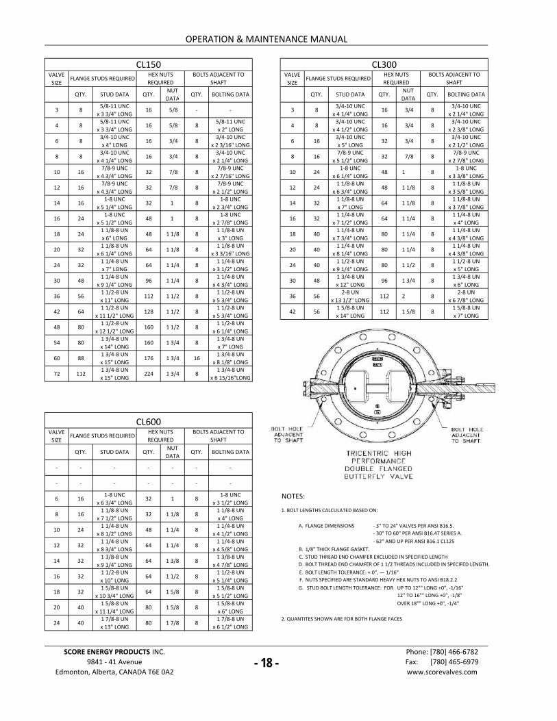
2. QUANTITES SHOWN ARE FOR BOTH FLANGE FACES
SCORE ENERGY PRODUCTS INC.
9841 - 41 Avenue
Edmonton, Alberta, CANADA T6E 0A2
Phone: [780] 466-6782
Fax: [780] 465-6979
www.scorevalves.com
- 3" TO 24" VALVES PER ANSI B16.5.
- 30" TO 60" PER ANSI B16.47 SERIES A.
- 62" AND UP PER ANSI B16.1 CL125
1/8" THICK FLANGE GASKET.
FLANGE DIMENSIONS
OVER 18"" LONG +0", -1/4"
STUD THREAD END CHAMFER EXCLUDED IN SPECIFIED LENGTH
BOLT THREAD END CHAMFER OF 1 1/2 THREADS INCLUDED IN SPECIFED LENGTH.
BOLT LENGTH TOLERANCE: + 0", — 1/16"
NUTS SPECIFIED ARE STANDARD HEAVY HEX NUTS TO ANSI B18.2.2
STUD BOLT LENGTH TOLERANCE: FOR UP TO 12"" LONG +0", -1/16"
12" TO 16"" LONG +0", -1/8"
CL600
FLANGE STUDS REQUIREDHEX NUTS
REQUIRED
BOLTS ADJACENT TO
SHAFT
OPERATION & MAINTENANCE MANUAL
CL150 CL300
FLANGE STUDS REQUIREDHEX NUTS
REQUIRED
BOLTS ADJACENT TO
SHAFTFLANGE STUDS REQUIRED
HEX NUTS
REQUIRED
BOLTS ADJACENT TO
SHAFT
- 18 -
- 19 - - 19 -
40 35
a • 30
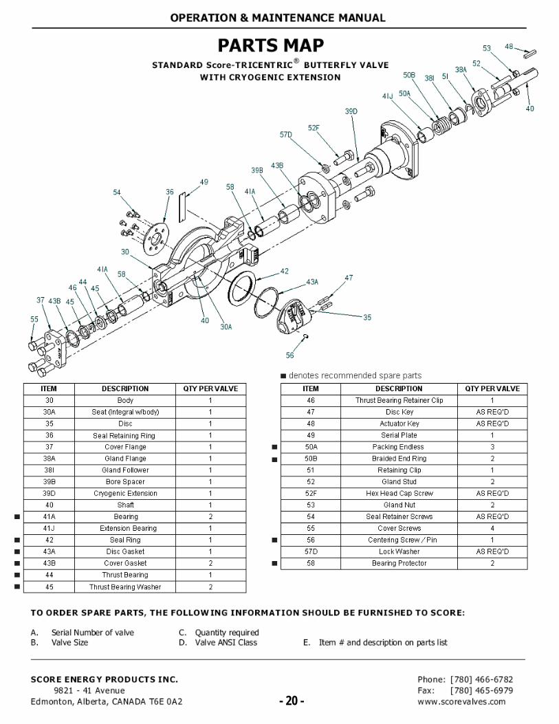
PARTS MAP STANDARD Score-TRICENTRIC® BUTTERFLY VALVE
WITH CRYOGENIC EXTENSION
53
506 381 51 38A
52
41J 50A
39D
52F 57D
398 436
58 41A
40
49 36
4IA
46 44
45
37 436 45
58 43A 47
30A
56
• denotes recommended spare parts
ITEM DESCRIPTION opt PER VALVE
30 Body 1 30A Seat (Integral Ai/body) 1 35 Disc 36 Seal Retaining Ring 37 Cover Flange
38A Gland Flange 1 381 Gland Follower 1 39B Bore Spacer 39D Cryogenic Extension 40 Shaft
41A Bearing 2 41J Extension Bearing
42 Seal Ring 43A Disc Gasket 43B Cover Gasket 2 44 Thrust Bearing
45 Thrust Bearing Washer 2
ITEM DESCRIPTION opt PER VALVE
46 Thrust Bearing Retainer Clip 1 47 Disc Key AS REQ'D 48 Actuator Key AS REQ'D 49 Serial Plate 1 50A Packing Endless 3
50B Braided End Ring 2 51 Retaining Clip 52 Gland Stud 2 52F Hex Head Cap Screw AS REQ'D 53 Gland Nut 2 54 Seal Retainer Screws AS REQ'D 55 Cover Screws 4
56 Centering Screw /Pin 1 57D Lock Washer AS REQ'D 58 Bearing Protector 2
■
■
■
■
■
■
■
OPERATION & MAINTENANCE MANUAL
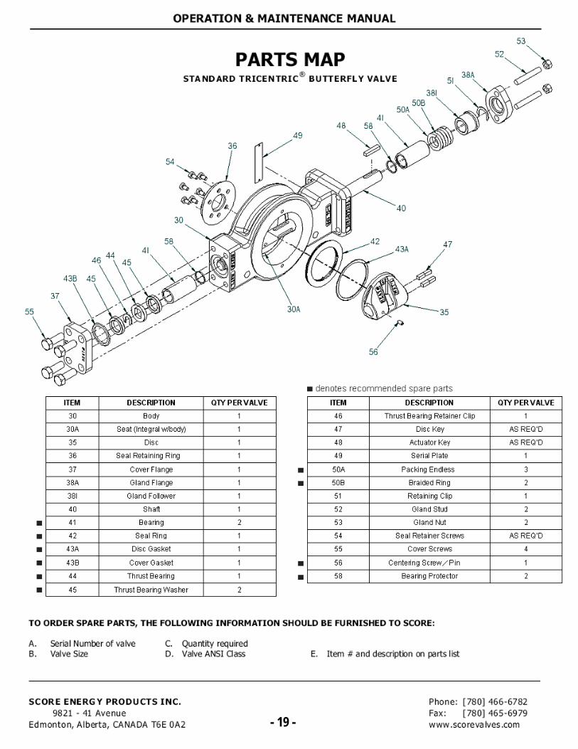
TO ORDER SPARE PARTS, THE FOLLOWING INFORMATION SHOULD BE FURNISHED TO SCORE:
A. Serial Number of valve
C. Quantity required B. Valve Size
D. Valve ANSI Class E. Item # and descriptbn on parts list
SCORE ENERGY PRODUCTS INC. Phone: [780) 466-6782 9821 - 41 Avenue
Fax: [780] 465-6979 Edmonton, Alberta, CANADA T6E 0A2
- 20 - vvww .sco re va Ives .com - 20 -


