LASERMET ICS-6 INSTRUCTION MANUAL - SweetsICS-6 Instruction Manual 01000-53-000 Page 6 of 47 Issue 2...
47
ICS-6 Instruction Manual 01000-53-000 Issue 2 6 May 2014 LASERMET ICS-6 INSTRUCTION MANUAL FAIL SAFE LASER INTERLOCK CONTROL SYSTEM
Transcript of LASERMET ICS-6 INSTRUCTION MANUAL - SweetsICS-6 Instruction Manual 01000-53-000 Page 6 of 47 Issue 2...

ICS-6 Instruction Manual
01000-53-000 Issue 2 6 May 2014
LASERMET ICS-6
INSTRUCTION MANUAL
FAIL SAFE LASER INTERLOCK CONTROL SYSTEM
ICS-6 Instruction Manual
01000-53-000 Page 2 of 47 Issue 2 6 May 2014
Lasermet ICS-6 Instruction Manual
Contents 1 Declaration of Conformity ........................................................................................ 4
2 Concept ................................................................................................................... 5
3 Summary of evaluation of compliance to EN ISO 13849-1:2008 ............................ 7
4 Installation ............................................................................................................... 8
4.1 Positioning ............................................................................................................ 8
5 Wiring .................................................................................................................... 10
5.1 Mains In ......................................................................................................... 10
5.2 ICS-6 Inputs ................................................................................................... 10
5.2.1 Mechanical Interlock Switches ................................................................. 10
5.2.3 Emergency Stop and Break Glass Switches ........................................... 15
5.2.4 Master Control and Connection to Fire Alarm .......................................... 16
5.3 ICS-6 Illuminated Sign Control Output ........................................................... 17
5.3.1 Mains Voltage Warning Signs .................................................................. 17
5.3.2 Low Voltage DC Warning Signs .............................................................. 19
5.4 Interlock Operator Output Contacts ................................................................ 21
5.4.1 Laser Power Supply (6 A max ) .............................................................. 21
5.4.2 Beam Shutters ......................................................................................... 22
5.4.3 Interlock Connectors ................................................................................ 26
5.4.4 Electro Magnetic Door Locks ................................................................... 27
5.5 Override ......................................................................................................... 29
5.5.1 Override / Entry Keypad .......................................................................... 29
5.5.3 Override Switch without Timer ................................................................. 31
5.5.4 Local Override ......................................................................................... 31
5.5.5 Override Alarm ........................................................................................ 32
5.6 Typical Installation .......................................................................................... 33
6 Expansion Boards ................................................................................................. 35
6.1 Introduction......................................................................................................... 35
6.2 Installing Expansion Boards ............................................................................... 35
7 Mismatch Detector ................................................................................................ 38
7.1 Description ..................................................................................................... 38
7.2 Configurable Options for Safety Circuit Mismatch Events .............................. 38
7.3 Clearing a Mismatch Fault Indication ............................................................. 39
7.4 Remote Test and Reset ................................................................................. 40
8 LED Indicators ....................................................................................................... 41
8.1 'Interlock' LED’s .............................................................................................. 41
8.2 ‘EXPN’ LED’s ................................................................................................. 41
8.3 'Safety Circuit Complete' LED’s ...................................................................... 41
8.4 Arm Button (illuminates blue) ......................................................................... 42
8.5 'Override On' LED .......................................................................................... 42
ICS-6 Instruction Manual
01000-53-000 Page 3 of 47 Issue 2 6 May 2014
8.6 ‘Mismatch Fault’ LED ..................................................................................... 42
8.7 'Laser Armed' LED ......................................................................................... 43
9 Operation .............................................................................................................. 44
9.1 Starting Up ..................................................................................................... 44
9.2 Resuming Operation after an Interlock Switch has been opened .................. 44
9.3 Using The Override ........................................................................................ 45
10 Specifications .................................................................................................... 46
11 Contact Details .................................................................................................. 47
ICS-6 Instruction Manual
01000-53-000 Page 4 of 47 Issue 2 6 May 2014
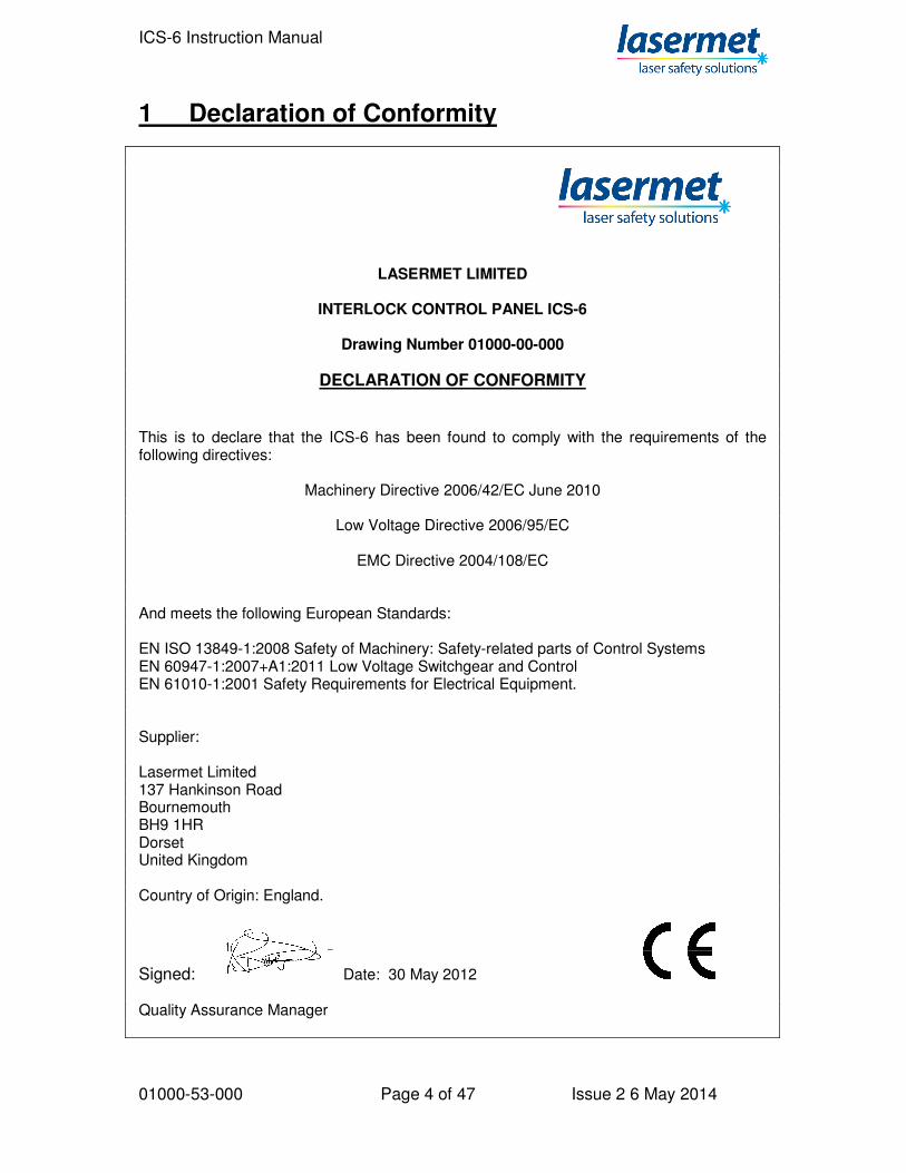
1 Declaration of Conformity
LASERMET LIMITED
INTERLOCK CONTROL PANEL ICS-6
Drawing Number 01000-00-000
DECLARATION OF CONFORMITY
This is to declare that the ICS-6 has been found to comply with the requirements of the following directives:
Machinery Directive 2006/42/EC June 2010
Low Voltage Directive 2006/95/EC
EMC Directive 2004/108/EC And meets the following European Standards: EN ISO 13849-1:2008 Safety of Machinery: Safety-related parts of Control Systems EN 60947-1:2007+A1:2011 Low Voltage Switchgear and Control EN 61010-1:2001 Safety Requirements for Electrical Equipment. Supplier: Lasermet Limited 137 Hankinson Road Bournemouth BH9 1HR Dorset United Kingdom Country of Origin: England.
Signed: Date: 30 May 2012 Quality Assurance Manager
ICS-6 Instruction Manual
01000-53-000 Page 5 of 47 Issue 2 6 May 2014
2 Concept The ICS-6 provides control of an interlock system primarily intended to protect persons from accidental exposure to hazardous lasers. It is able to monitor several doors, windows, curtains etc. fitted with safety interlock switches and disable the laser if any are open. In this manual the term ‘Door Switch’ refers to any interlock switch which may be fitted to a door, cover, window blind etc. The versatile ICS-6 system can be connected to any number of door switches and can indicate the status of up to 4 switches or groups of switches. An Arm Laser button is provided to arm the laser when all the safety requirements are met. A key lock prevents unauthorised use of the system. The ICS-6 has a fully dual channel cross-checked architecture and when correctly wired can realise a system compliant with EN ISO 13849-1 up to performance level ‘e’. Three safety interlock outputs each rated at 6A resistive, 250Vac, are provided to enable the laser, operate door locks etc. The interlock outputs are volt-free contacts which close when the system is armed. Each contact actually comprises two contacts in series. In the event of one contact failing to open, the other contact will open and the system is then disabled, preventing further use and maintaining safety. The contacts can be configured for a variety of options. The ICS-6 is available in enhanced versions which offer the following options:
Nine Interlock Output contacts, seven rated at 8A, 50VDC maximum and two rated at 8A, 250Vac.
Three-pole safety power contactors which may be used to switch single or three-phase laser mains supplies.
A separate changeover contact is provided for operating one or two-way illuminated warning signs. The ICS-6 is able to monitor output devices such as contactors and shutters with feedback (such as Lasermet’s LS-20 beam shutter) and the signs will display a danger indication in the event of a monitored output device failing or partly failing to assume the safe state when the system is disarmed. A remote master switch or master interlock system may be connected such that one or more ICS-6’s can be controlled by one central point. The master system can prevent the ICS-6 and it’s associated laser from being armed. The ICS-6 can be linked to a fire alarm so that the laser is disarmed and any controlled doors are unlocked in the event of an alarm. Other features include emergency stop control with indication, and provision for an entry/exit timed override option with pushbutton or coded keypad entry. The system may be interconnected with site access control systems.

ICS-6 Instruction Manual
01000-53-000 Page 6 of 47 Issue 2 6 May 2014
The ICS-6 has a mismatch detector which when wired to a full dual-channel system disables the system in the event of a mismatch between the two safety circuits. This provides protection against the failure of a door switch etc. The ICS-6 can accommodate expansion modules internally, and Lasermet have a range of modules either available or in development including: Uncommitted Relays; Active Beamguard; Safety Logic Plus; Network Interface. Lasermet provides a full range of equipment including interlock switches, illuminated warning signs, laser shutters, entry keypads with built-in fail-safe override timer, door locks, external power supplies etc. which can be connected to the ICS-6 to provide a complete system. Full support, design and installation is available from Lasermet, please contact us for any queries. Contact details are given at the end of this manual.

ICS-6 Instruction Manual
01000-53-000 Page 7 of 47 Issue 2 6 May 2014
3 Summary of evaluation of compliance to EN ISO 13849-1:2008
Note that this summary relates to the ICS-6 controller only. To achieve a complete system performance level ‘e’ the system must be wired as described in this manual using suitably rated door sensors and measures taken to minimise the effects of common cause failures in the sensors and wiring which may be connected to the unit. Required characteristics:- Architecture Category 3/4 Performance Level Required (PLr) PLr = e Application Demand base:- In service operation 365 days/year Functional demand on the controller once per hour Achieved characteristics:- Architecture Category 4 Performance Level (PL) PL = e PFH [1/h] 2.47xE-8 MTTFd 100 years Mission time 20 years.
ICS-6 Instruction Manual
01000-53-000 Page 8 of 47 Issue 2 6 May 2014
4 Installation The ICS-6 is designed to be permanently attached to a wall or other fixed vertical surface.
4.1 Positioning The ICS-6 should be mounted in a convenient position for use and wiring. During use it will be necessary for operators to access the controls and to observe the indications. For rooms where personnel may work inside while the laser is operating this is often near the main entry door but it can be near the working position within the room if preferred. For enclosures which personnel leave before activating the laser, the ICS-6 may be fitted on the outside of the enclosure itself or somewhere convenient nearby. During installation, wired connections will need to be made from the ICS-6 to all the interlocked doors, warning signs, laser interlocks, shutters and other equipment as required by the system, and allowance should be made for the installation of electrical conduits, trunking etc. to make entry to the unit. There should be adequate clearance beneath the unit to allow the front door to be fully opened downwards. Installation will be impaired if the door cannot be fully opened. Care should be taken that any conduit or trunking beneath the unit will allow the door to open sufficiently. To open the unit, unlock the catch by turning the lock with a flat screwdriver until the slot is horizontal. Press the release bar downwards and the cover will unlock. It can then be hinged downwards and will snap into the upright position. Four Ø5mm fixing holes are provided in the four corners of the case for mounting purposes. The cables for mains supply, door switches, laser control etc. are usually fed to the unit through plastic trunking or 22mm diameter plastic conduit, and holes are required to be made in the case to accommodate the entry points. An electrician’s conduit hole cutter is the ideal tool for this purpose. The conduit may be surface mounted or buried in the wall, and should be arranged to ensure that holes can be made in the enclosure in the required positions. If surface-mounted conduit is used the top and bottom faces of the case will usually be found to provide the most convenient entry points. All connections are made on the narrow circuit board located in the bottom of the case. All of the terminals are identified on the circuit board. The connection circuit board may be temporarily removed during installation. With the exception of the 9-way Interlock option in the shallow case, the board can also be refitted in any of three different locations in the case to suit the cable entry points.
ICS-6 Instruction Manual
01000-53-000 Page 9 of 47 Issue 2 6 May 2014
Care should be taken in the running of conduits that the proposed entry position in the ICS-6 can be accommodated and that the front cover of the ICS-6 can be opened.
ICS-6 Instruction Manual
01000-53-000 Page 10 of 47 Issue 2 6 May 2014
5 Wiring Warning This unit operates from mains electricity. There is mains voltage on the circuit boards and some of the terminals. Always disconnect the mains power supply before opening the unit or attempting any wiring alterations. The ICS-6 is a versatile interlock system and there are a variety of ways in which it can be used. Be sure you know which configuration you require before you attempt to wire the unit. If you require further assistance please call Lasermet technical help. Contact details are at the end of this manual. All connections are made to plug-in terminals on the narrow circuit board located in the bottom half of the case. It is usually easiest to unplug the terminals while the connections are being made. A 2.5mm slotted screwdriver will be needed to access the smaller terminals.
5.1 Mains In (110V to 240V ac 50-60Hz) The ICS-6 has a universal mains voltage input and does not need setting for different supply voltages. It is recommended that a fused switched spur or equivalent is provided for the mains supply to the unit, fused between 3A and 8A, depending on the amount of additional equipment connected to the ICS-6. We recommend that a switched fused spur with neon indicator is provided. In all cases the supply must be protected by an overcurrent device not exceeding 8A. Wire the incoming mains power to the following terminals on the narrow circuit board in the bottom of the case: Live - L IN Neutral - N IN Earth - E
5.2 ICS-6 Inputs 5.2.1 Mechanical Interlock Switches Up to four door interlock switches may be directly wired to the ICS-6. By making external connections, more switches can be added and arranged in groups for indication purposes. The interlock switches are wired to the terminals labelled INTERLOCK 1 through to
ICS-6 Instruction Manual
01000-53-000 Page 11 of 47 Issue 2 6 May 2014
INTERLOCK 4. Each interlock switch should have two safety contacts which are closed when the door is closed. Some door contacts such as Lasermet’s IS-MECH switches have an additional monitor contact which closes when the door is opened. This is not used in ICS-6. A 4-way terminal block is provided for each door interlock switch. One of the safety contacts which are closed when the door is closed is wired to the ‘A’ terminals. The other safety contact is wired to the ‘B’ terminals. If the system is required to perform to ISO 13849 performance level ‘e’, two switches are usually required to be fitted to each door, with the safety contact of one switch wired to the ‘A’ terminals and the safety contact from the second switch wired in a separate cable to the ‘B’ terminals. If there is any possibility of both cables being damaged for the same reason simultaneously it may also be necessary to route the cables in different paths. If the laser hazard is considered low it is possible to use switches with only one safety contact. In this case connect the switch across the ‘A’ terminals. Fit a wire link across the ‘B’ terminals. The Mismatch Detector cannot be used and must be disabled, see the Mismatch Detector section below. It is usual to use low voltage 4-core flexible cable for these connections and Lasermet can supply suitable cable in standard pvc or low smoke zero halogen (LSZH) types. If an Interlock input is not used, one wire link should be fitted to connect the ‘A’ terminals together, and a second wire link to connect the ‘B’ terminals on each unused terminal block. The example diagram below shows a system with two doors wired for ISO 13849 performance level ‘e’. Each door has two switches.

ICS-6 Instruction Manual
01000-53-000 Page 12 of 47 Issue 2 6 May 2014
A
B
B
A
INTERLOCK
1
INTERLOCK
2
INTERLOCK
3
INTERLOCK
4
Door
Interlock
Switch 1A
Wire
Links
Wire
Links
NOTE:
Door Interlock Switches
shown with door closed.
Door
Interlock
Switch 1B
Door 1
Door
Interlock
Switch 2A
Door
Interlock
Switch 2B
Door 2
A
B
B
A
A
B
B
A
A
B
B
A
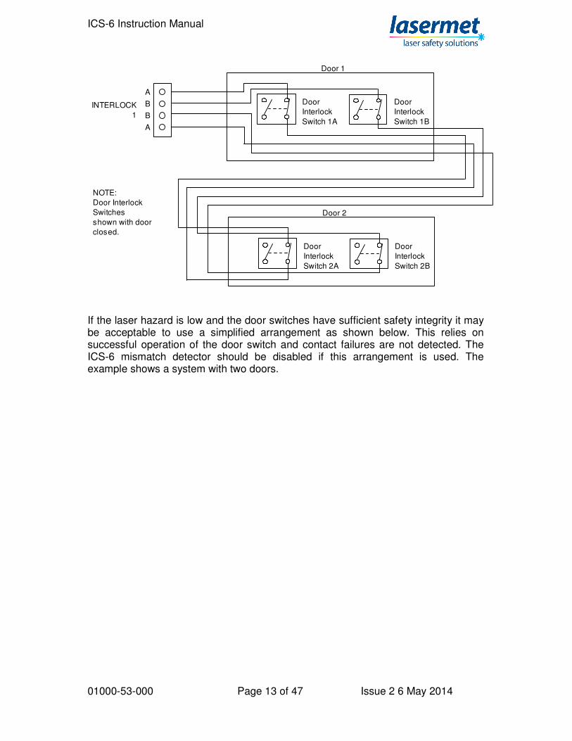
If you have more than four doors you can wire them in groups. A common situation is where there are double doors. Interlock switches need to be fitted to both, and the two doors can then be wired together so that a single monitor indication light will illuminate on the front panel of the ICS-6 if either of the doors is open. The switches in a group should be wired with their safety contacts in series. Each group may have several switches. An example diagram for two door interlock switches wired in a group is shown below.
ICS-6 Instruction Manual
01000-53-000 Page 13 of 47 Issue 2 6 May 2014
A
B
B
A
INTERLOCK
1
Door
Interlock
Switch 1A
Door
Interlock
Switch 1B
Door 1
Door
Interlock
Switch 2A
Door
Interlock
Switch 2B
Door 2
NOTE:
Door Interlock
Switches
shown with door
closed.
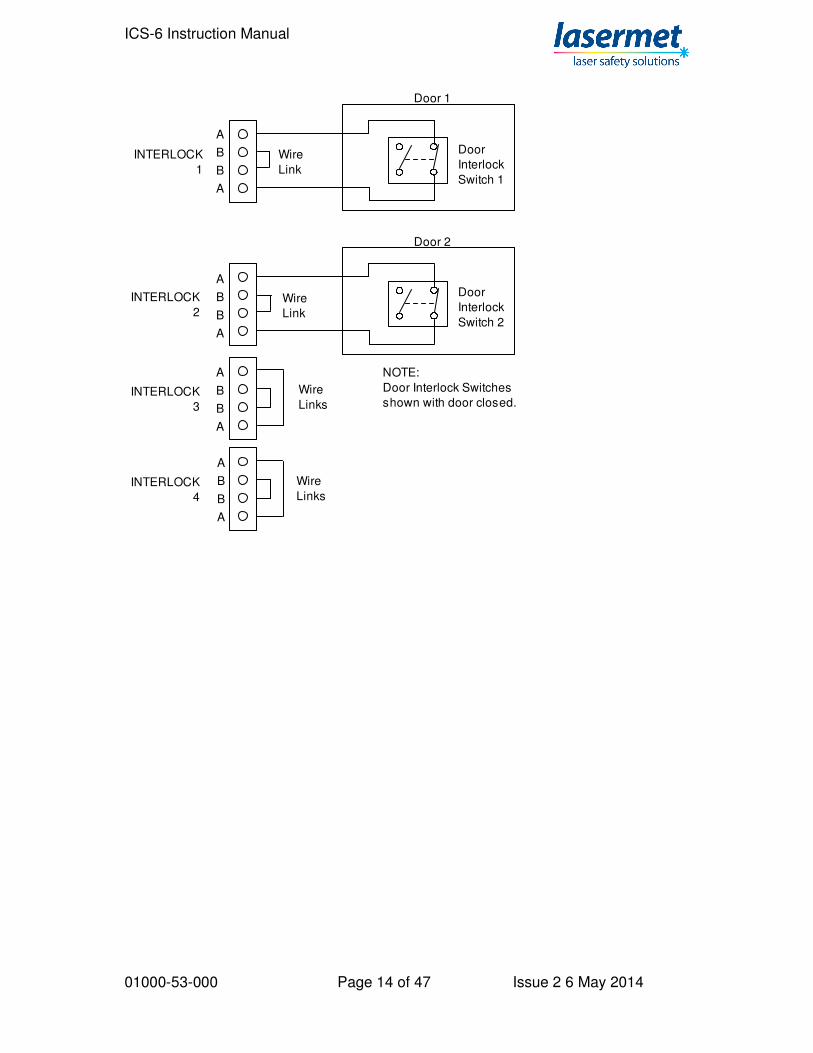
If the laser hazard is low and the door switches have sufficient safety integrity it may be acceptable to use a simplified arrangement as shown below. This relies on successful operation of the door switch and contact failures are not detected. The ICS-6 mismatch detector should be disabled if this arrangement is used. The example shows a system with two doors.
ICS-6 Instruction Manual
01000-53-000 Page 14 of 47 Issue 2 6 May 2014
A
B
B
A
INTERLOCK
1
INTERLOCK
2
INTERLOCK
3
INTERLOCK
4
Door
Interlock
Switch 1
Wire
Links
Wire
Links
NOTE:
Door Interlock Switches
shown with door closed.
Door 1
Door
Interlock
Switch 2
Door 2
A
B
B
A
A
B
B
A
A
B
B
A
Wire
Link
Wire
Link
ICS-6 Instruction Manual
01000-53-000 Page 15 of 47 Issue 2 6 May 2014
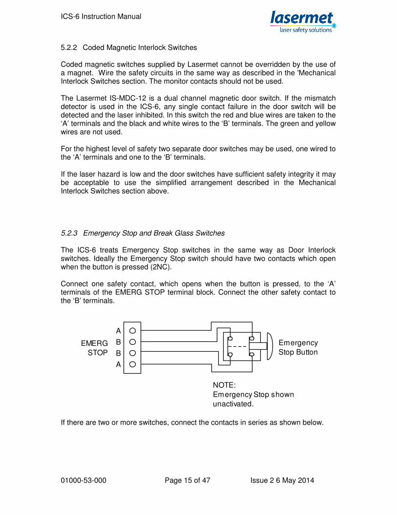
5.2.2 Coded Magnetic Interlock Switches Coded magnetic switches supplied by Lasermet cannot be overridden by the use of a magnet. Wire the safety circuits in the same way as described in the 'Mechanical Interlock Switches section. The monitor contacts should not be used. The Lasermet IS-MDC-12 is a dual channel magnetic door switch. If the mismatch detector is used in the ICS-6, any single contact failure in the door switch will be detected and the laser inhibited. In this switch the red and blue wires are taken to the ‘A’ terminals and the black and white wires to the ‘B’ terminals. The green and yellow wires are not used. For the highest level of safety two separate door switches may be used, one wired to the ‘A’ terminals and one to the ‘B’ terminals. If the laser hazard is low and the door switches have sufficient safety integrity it may be acceptable to use the simplified arrangement described in the Mechanical Interlock Switches section above. 5.2.3 Emergency Stop and Break Glass Switches The ICS-6 treats Emergency Stop switches in the same way as Door Interlock switches. Ideally the Emergency Stop switch should have two contacts which open when the button is pressed (2NC). Connect one safety contact, which opens when the button is pressed, to the ‘A’ terminals of the EMERG STOP terminal block. Connect the other safety contact to the ‘B’ terminals.
A
B
B
A
EMERG
STOP
Emergency
Stop Button
NOTE:
Emergency Stop shown
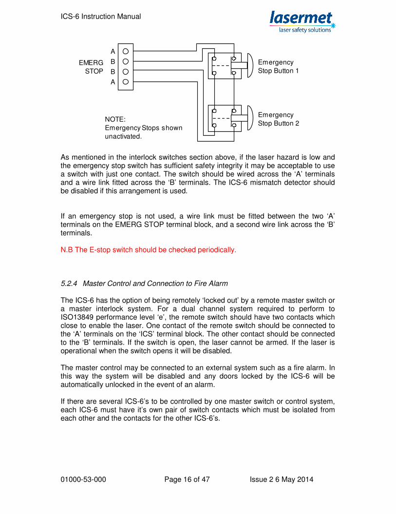
unactivated. If there are two or more switches, connect the contacts in series as shown below.
ICS-6 Instruction Manual
01000-53-000 Page 16 of 47 Issue 2 6 May 2014
A
B
B
A
EMERG
STOP
Emergency
Stop Button 1
NOTE:
Emergency Stops shown
unactivated.
Emergency
Stop Button 2
As mentioned in the interlock switches section above, if the laser hazard is low and the emergency stop switch has sufficient safety integrity it may be acceptable to use a switch with just one contact. The switch should be wired across the ‘A’ terminals and a wire link fitted across the ‘B’ terminals. The ICS-6 mismatch detector should be disabled if this arrangement is used. If an emergency stop is not used, a wire link must be fitted between the two ‘A’ terminals on the EMERG STOP terminal block, and a second wire link across the ‘B’ terminals. N.B The E-stop switch should be checked periodically. 5.2.4 Master Control and Connection to Fire Alarm The ICS-6 has the option of being remotely ‘locked out’ by a remote master switch or a master interlock system. For a dual channel system required to perform to ISO13849 performance level ‘e’, the remote switch should have two contacts which close to enable the laser. One contact of the remote switch should be connected to the ‘A’ terminals on the ‘ICS’ terminal block. The other contact should be connected to the ‘B’ terminals. If the switch is open, the laser cannot be armed. If the laser is operational when the switch opens it will be disabled. The master control may be connected to an external system such as a fire alarm. In this way the system will be disabled and any doors locked by the ICS-6 will be automatically unlocked in the event of an alarm. If there are several ICS-6’s to be controlled by one master switch or control system, each ICS-6 must have it’s own pair of switch contacts which must be isolated from each other and the contacts for the other ICS-6’s.
ICS-6 Instruction Manual
01000-53-000 Page 17 of 47 Issue 2 6 May 2014
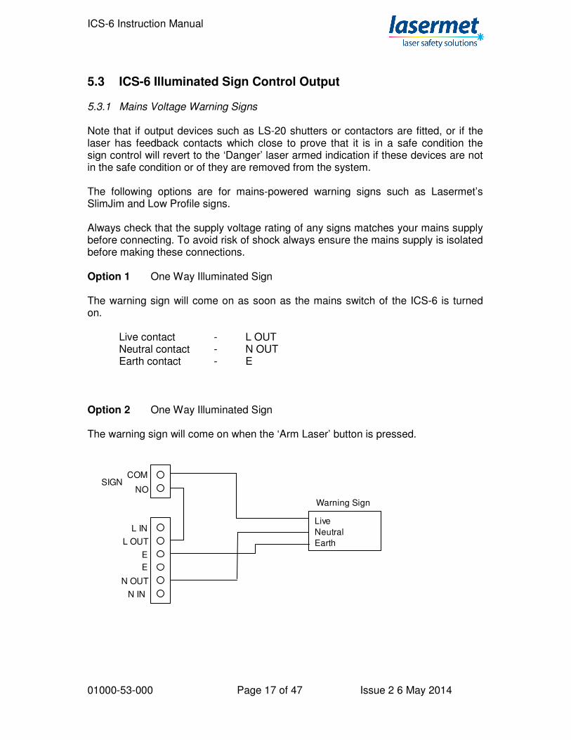
5.3 ICS-6 Illuminated Sign Control Output 5.3.1 Mains Voltage Warning Signs Note that if output devices such as LS-20 shutters or contactors are fitted, or if the laser has feedback contacts which close to prove that it is in a safe condition the sign control will revert to the ‘Danger’ laser armed indication if these devices are not in the safe condition or of they are removed from the system. The following options are for mains-powered warning signs such as Lasermet’s SlimJim and Low Profile signs. Always check that the supply voltage rating of any signs matches your mains supply before connecting. To avoid risk of shock always ensure the mains supply is isolated before making these connections. Option 1 One Way Illuminated Sign The warning sign will come on as soon as the mains switch of the ICS-6 is turned on. Live contact - L OUT Neutral contact - N OUT Earth contact - E Option 2 One Way Illuminated Sign The warning sign will come on when the ‘Arm Laser’ button is pressed.
Warning Sign
Live
Neutral
Earth
L IN
L OUT
E
E
N IN
N OUT
SIGNCOM
NO
ICS-6 Instruction Manual
01000-53-000 Page 18 of 47 Issue 2 6 May 2014
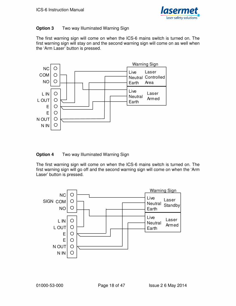
Option 3 Two way Illuminated Warning Sign The first warning sign will come on when the ICS-6 mains switch is turned on. The first warning sign will stay on and the second warning sign will come on as well when the ‘Arm Laser’ button is pressed.
Warning Sign
Live
Neutral
Earth
Live
Neutral
Earth
Laser
Controlled
Area
Laser
ArmedL IN
L OUT
E
E
N IN
N OUT
COM
NO
NC
Option 4 Two way Illuminated Warning Sign The first warning sign will come on when the ICS-6 mains switch is turned on. The first warning sign will go off and the second warning sign will come on when the ‘Arm Laser’ button is pressed.
Warning Sign
Live
Neutral
Earth
L IN
L OUT
E
E
N IN
N OUT
Live
Neutral
Earth
Laser
Standby
Laser
Armed
SIGN COM
NO
NC
ICS-6 Instruction Manual
01000-53-000 Page 19 of 47 Issue 2 6 May 2014
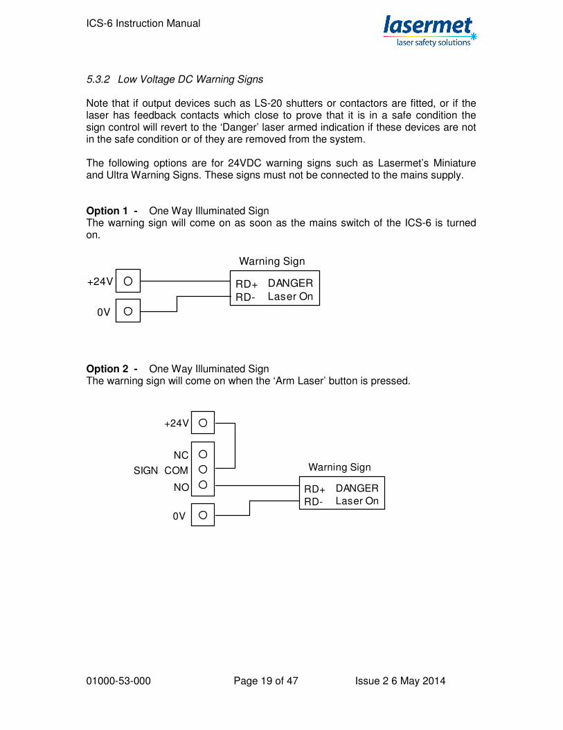
5.3.2 Low Voltage DC Warning Signs Note that if output devices such as LS-20 shutters or contactors are fitted, or if the laser has feedback contacts which close to prove that it is in a safe condition the sign control will revert to the ‘Danger’ laser armed indication if these devices are not in the safe condition or of they are removed from the system. The following options are for 24VDC warning signs such as Lasermet’s Miniature and Ultra Warning Signs. These signs must not be connected to the mains supply. Option 1 - One Way Illuminated Sign The warning sign will come on as soon as the mains switch of the ICS-6 is turned on.
Warning Sign
RD+
RD-
+24V
0V
DANGER
Laser On
Option 2 - One Way Illuminated Sign The warning sign will come on when the ‘Arm Laser’ button is pressed.
Warning Sign
RD+
RD-
+24V
0V
DANGER
Laser On
SIGN COM
NO
NC
ICS-6 Instruction Manual
01000-53-000 Page 20 of 47 Issue 2 6 May 2014
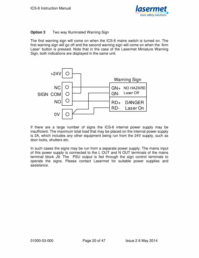
Option 3 Two way Illuminated Warning Sign The first warning sign will come on when the ICS-6 mains switch is turned on. The first warning sign will go off and the second warning sign will come on when the ‘Arm Laser’ button is pressed. Note that in the case of the Lasermet Miniature Warning Sign, both indications are displayed in the same unit.
Warning Sign
RD+
RD-
+24V
0V
DANGER
Laser On
SIGN COM
NO
GN+
GN-
NO HAZARD
Laser Off
NC
If there are a large number of signs the ICS-6 internal power supply may be insufficient. The maximum total load that may be placed on the internal power supply is 2A, which includes any other equipment being run from the 24V supply, such as door locks, shutters etc. In such cases the signs may be run from a separate power supply. The mains input of this power supply is connected to the L OUT and N OUT terminals of the mains terminal block J9. The PSU output is fed through the sign control terminals to operate the signs. Please contact Lasermet for suitable power supplies and assistance.
ICS-6 Instruction Manual
01000-53-000 Page 21 of 47 Issue 2 6 May 2014
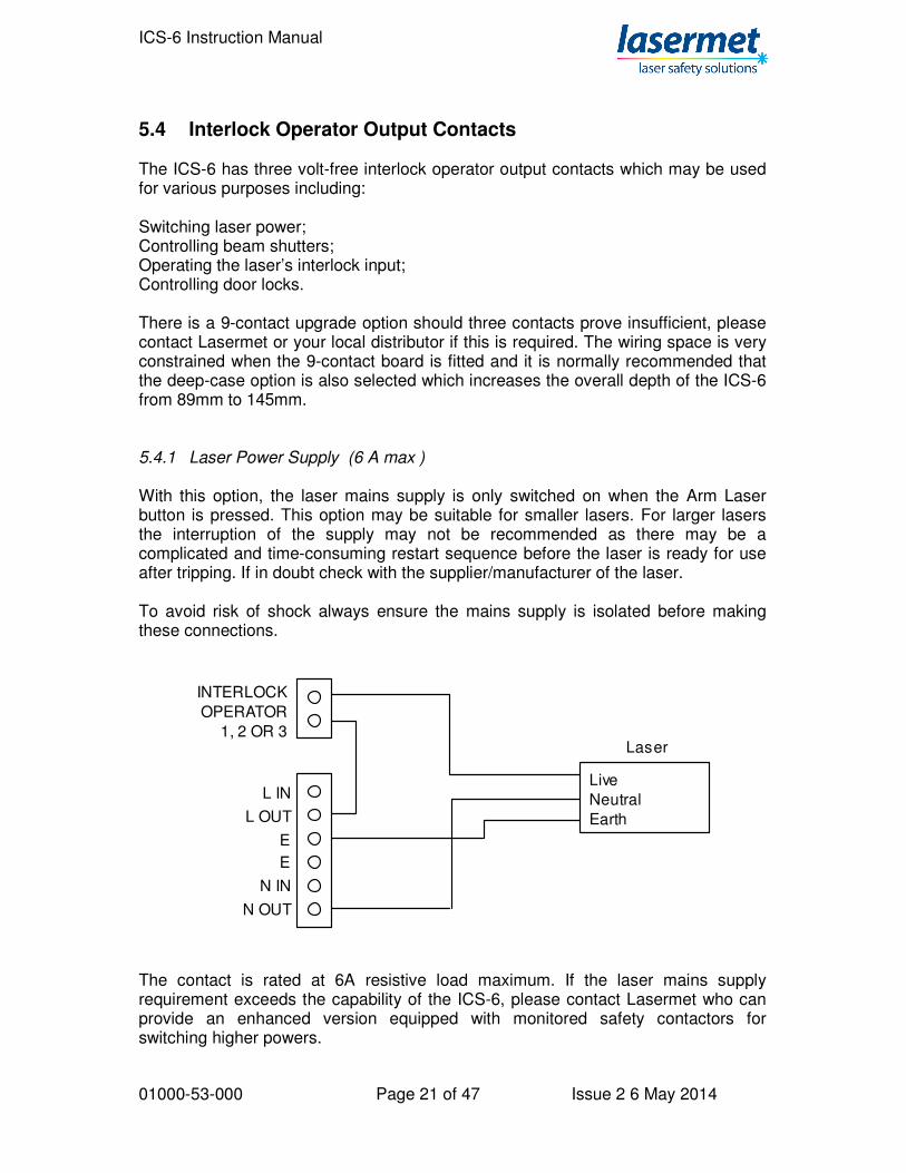
5.4 Interlock Operator Output Contacts The ICS-6 has three volt-free interlock operator output contacts which may be used for various purposes including: Switching laser power; Controlling beam shutters; Operating the laser’s interlock input; Controlling door locks. There is a 9-contact upgrade option should three contacts prove insufficient, please contact Lasermet or your local distributor if this is required. The wiring space is very constrained when the 9-contact board is fitted and it is normally recommended that the deep-case option is also selected which increases the overall depth of the ICS-6 from 89mm to 145mm. 5.4.1 Laser Power Supply (6 A max ) With this option, the laser mains supply is only switched on when the Arm Laser button is pressed. This option may be suitable for smaller lasers. For larger lasers the interruption of the supply may not be recommended as there may be a complicated and time-consuming restart sequence before the laser is ready for use after tripping. If in doubt check with the supplier/manufacturer of the laser. To avoid risk of shock always ensure the mains supply is isolated before making these connections.
Laser
Live
Neutral
Earth
L IN
L OUT
E
E
N IN
N OUT
INTERLOCK
OPERATOR
1, 2 OR 3
The contact is rated at 6A resistive load maximum. If the laser mains supply requirement exceeds the capability of the ICS-6, please contact Lasermet who can provide an enhanced version equipped with monitored safety contactors for switching higher powers.

ICS-6 Instruction Manual
01000-53-000 Page 22 of 47 Issue 2 6 May 2014
5.4.2 Beam Shutters The ICS-6 may operate one or more beam shutters and one or more laser interlocks. For permanent fixed installations these may be directly wired to the ICS-6. Where there is any possibility of the equipment being changed or moved it is often most convenient to be able to unplug the equipment. Lasermet provide a range of small distribution boxes which allow for convenient positioning of wall or surface-mounted plugs for laser interlocks and sockets for shutters. The boxes are available with different combinations of plugs and sockets. Most lasers only have a single channel interlock input which can present problems if the safety system has to comply with ISO 13849 performance level ‘e’ since two methods of control are usually required. Some lasers have internal beam shutters which may be controlled by the ICS-6. If the laser has two means of disabling e.g. interlock and internal shutter it is recommended that both are used. Otherwise it may be necessary to consider having an external shutter in addition to the laser’s own interlock if a high safety integrity is required. Lasermet’s beam shutters are supplied with suitable leads to plug into the distribution boxes. Open-ended leads are provided for laser interlocks allowing the customer to fit the correct plug for his laser. Laser Shutter Supply (12 VDC 0.8 A maximum or 24 VDC, 1.5 A maximum) The ICS-6 has a built-in DC supply for operating laser shutters, and is able to provide both continuous and switched supplies using one of the Interlock Operator outputs. Several shutters of the same type may all be powered from one Interlock Operator contact, please contact Lasermet for details if required. NOTE: The selected Interlock Operator used for switching shutters must not be used for any other purpose. If your shutter power requirements exceed 0.8 A at 12V or 1.5A at 24VDC, or if there is additional equipment such as low voltage warning signs or door locks powered by the ICS-6, the ICS-6 internal power supply may be insufficient. The maximum total load that may be placed on the internal power supply is 2A, which includes any other equipment being run from the 24V supply, such as door locks, signs etc. In such cases the shutter may be run from a separate power supply. The mains input of this power supply is connected to the L OUT and N OUT terminals of the mains terminal block J9. The PSU output is fed through the interlock operator terminals to operate the shutter. Please contact Lasermet for suitable power supplies and assistance.

ICS-6 Instruction Manual
01000-53-000 Page 23 of 47 Issue 2 6 May 2014
Shutter
Continuous Supply
Sw itched Supply
0V
+24V
+24V
+12V
+12V
0V
0V
INTERLOCKOPERATOR
1, 2 OR 3
DCPOWER
OUT
Select appropriate supply voltage
LS-10 uses 12 or 24V.
LS-100 uses 12V.
12
3
12
3
Plug
Distribution
Box
Viewed from
front
Lead
Socket
LS-10 Shutter Use the above circuit set to 24VDC. The Continuous Supply wire (pin 3) may be omitted for standard LS-10 shutters. LS-100 Shutter Use this circuit set to 12VDC. The Continuous Supply wire must be included to allow the cooling fan of LS-100 to operate. LS-20 Shutter The LS-20 Shutter can use the above circuit set to 24VDC, however it is recommended that the monitoring circuit shown below is included to allow the ICS-6 to monitor the shutter and to detect any faults. If using the LS-20 SIL3 twin shutter the circuit below must be used to achieve the SIL3 / PL ‘e’ rating.

ICS-6 Instruction Manual
01000-53-000 Page 24 of 47 Issue 2 6 May 2014
InterlockOutput
+24V
+24V
+12V
+12V
0V
0V
DCPOWER
OUT
Interlock System ICS-6
Control Supply +24V
Monitor Supply +24V
0V
LS-20 Shutter
OUTPUTMONITOR
1
1
2
2
Monitor Contact 1 ‘Closed’
Monitor Contact 1 Common
Monitor Contact 2 ‘Closed’
Monitor Contact 2 Common
The LS-20 Shutter has it’s own distribution socket. The wiring connections inside the distribution box are shown below:
1
6
J3
J2
CONTROL +24V SUPPLY
0V
MONITOR +24V SUPPLY
REMOTE OPEN 24V INPUT
OPEN STATUS 24V OUTPUT
CLOSED STATUS 24V OUTPUT
MONITOR CONTACT 1 OPEN
MONITOR CONTACT 1 COMMON
MONITOR CONTACT 1 CLOSED
MONITOR CONTACT 2 OPEN
MONITOR CONTACT 2 COMMON
MONITOR CONTACT 2 CLOSED

ICS-6 Instruction Manual
01000-53-000 Page 25 of 47 Issue 2 6 May 2014
Laser Shutter - with own power supply If your shutters have their own power supply or are to be run from an existing supply, you can use an Interlock Operator contact to operate them. The connections should be arranged so that the shutter closes when the Interlock Operator contact opens. If an Interlock Operator is used for this purpose it must not be connected to any other circuit. The contact is limited to 6A resistive load. If your shutter is solenoid-based it may need a protection diode fitted to prevent possible damage to the contact.

ICS-6 Instruction Manual
01000-53-000 Page 26 of 47 Issue 2 6 May 2014
5.4.3 Interlock Connectors Any of the interlock operator contacts may be used to operate a laser’s interlock control, provided they haven’t been used for any other purpose. The contacts are closed when the ICS-6 Arm Laser button is pressed. If there is more than one laser each must have it’s own contact. Interlock sockets of several lasers must not be connected together. A Lasermet Distribution Box is usually used to provide a connection point convenient to the laser. In this case the interlock operator contact is connected to pins 1 and 2 of the plug of the distribution box. Leads are available in various lengths to plug into the distribution box. The other end of the lead is unconnected to allow fitment of a plug suitable for the laser.
Laser
Interlock
Connector
INTERLOCKOPERATOR
1, 2 OR 3
12
3
12
3Socket
Distribution
Box
Viewed from
front
Lead
Plug
Some lasers are now being designed to be compliant with EN 13849-1 and feature two interlock inputs. This will require two ICS-6 interlock operator contacts and a ideally a distribution plug and socket with more connections. Furthermore some lasers also include one or two ‘laser safe’ contacts which can be monitored by the ICS-6. In this instance if either or both ‘laser safe’ contacts are not closed the ICS-6 will set illuminated warning signs to the danger indication and inhibit arming of the laser. Depending on the safety performance of the laser itself such a system could meet EN 13849-1 performance level ‘e’. The wiring of such a laser is shown below. Please contact Lasermet for assistance with distribution boxes, connectors and leads if required. If other devices are using the Output Monitor terminals, for example an LS-20 shutter, all the safe proving contacts for each channel should be wired in series to the Output Monitor connector such that the circuit is complete when all devices are in the safe condition.

ICS-6 Instruction Manual
01000-53-000 Page 27 of 47 Issue 2 6 May 2014
LASER
Interlock
Input 1INTERLOCK
OPERATORS
Distribution
Box
8-Core
LeadPlug
OUTPUT
MONITOR
J14
A
A
B
B
Interlock
Input 2
Laser Safe
Contact 1
Laser Safe
Contact 2
ICS-6
5.4.4 Electro Magnetic Door Locks Use only fail safe door locks provided by Lasermet (electric door strikes or maglocks). These will prevent access to the room while the laser is on while always allowing people to enter or leave the room in the event of a power loss. In order to ensure that people can always enter or leave the room in the event of an emergency it will be necessary to put an emergency stop or break glass switch near each door. If in doubt call Lasermet technical help. The door should be fitted with interlock switches (see section 5.2) so that the laser is disabled if a door is opened using the breakglass switch.
Magnetic Door Lock
set to 24VDC
Supply
+24V
+24V
+12V
+12V
0V
0V
INTERLOCK
OPERATOR
1, 2 OR 3
DC
POWER
OUT
Internal
Emergency
Door Release
Breakglass
Protection Diode,
see text.
External
Emergency
Door Release
Breakglass
-
+

ICS-6 Instruction Manual
01000-53-000 Page 28 of 47 Issue 2 6 May 2014
Note that the total combined current available from the 24V and 12V outputs from the ICS-6 is 2A, and the maximum current from the 12V output is 1A, so whilst both shutters and door locks may be used at the same time, care should be taken not to exceed this rating in total. The locks supplied by Lasermet can be configured for 12V or 24V supply. They should be set for 24V operation to reduce the current consumption to 0.25A per lock. To set the Maglock for 24V operation, open the terminal access cover on the lock. Remove the two black links from the circuit board and refit one of them across the middle two pins. Park the spare link with one side on one of the empty end pins so it is not lost. If in doubt, refer to the instructions supplied with the maglock. If the ICS Power Output is not compatible or sufficient for the door locks, the door locks should be powered by an external power supply with it’s live main terminal connected through one of the Interlock Operators. Laermet can supply such power supplies on request. In all cases a diode rated at 1A 50V or more must be wired directly across the terminals of each door lock. Lasermet’s Maglocks usually have the diode fitted as standard, in which case it is essential that the supply is connected the right way round. Refer also to the keypad section below if an ICS-KP12 keypad is being fitted.
ICS-6 Instruction Manual
01000-53-000 Page 29 of 47 Issue 2 6 May 2014
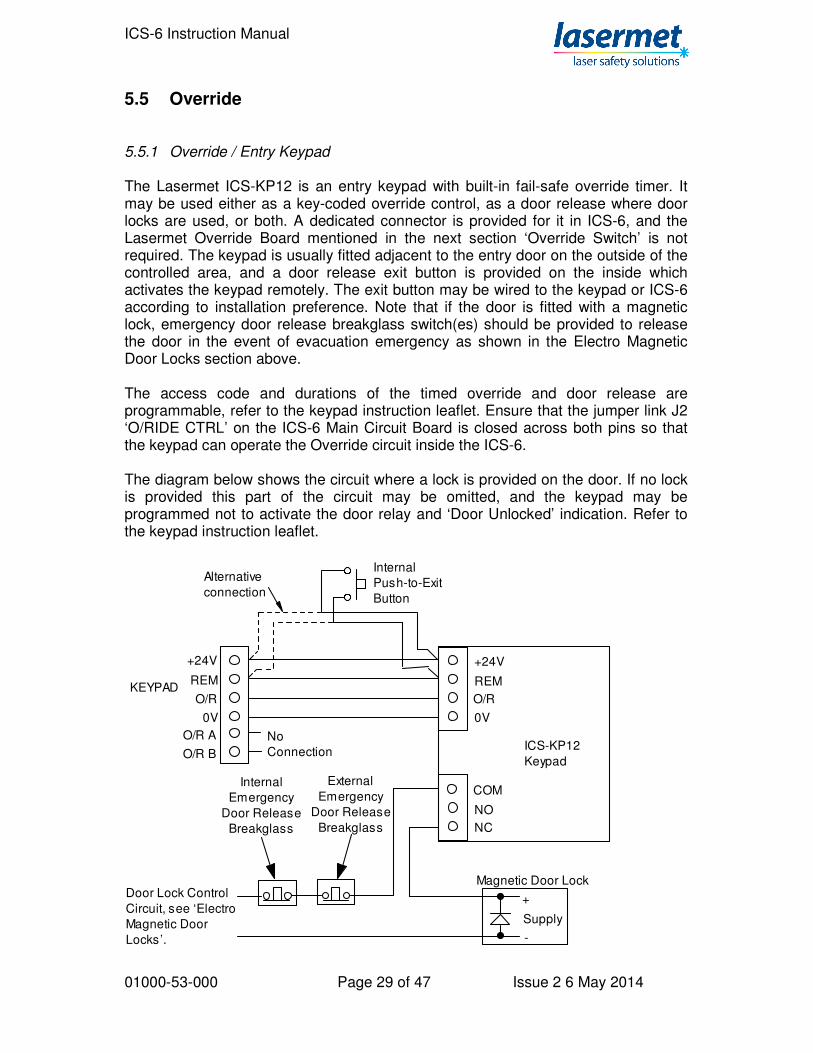
5.5 Override 5.5.1 Override / Entry Keypad The Lasermet ICS-KP12 is an entry keypad with built-in fail-safe override timer. It may be used either as a key-coded override control, as a door release where door locks are used, or both. A dedicated connector is provided for it in ICS-6, and the Lasermet Override Board mentioned in the next section ‘Override Switch’ is not required. The keypad is usually fitted adjacent to the entry door on the outside of the controlled area, and a door release exit button is provided on the inside which activates the keypad remotely. The exit button may be wired to the keypad or ICS-6 according to installation preference. Note that if the door is fitted with a magnetic lock, emergency door release breakglass switch(es) should be provided to release the door in the event of evacuation emergency as shown in the Electro Magnetic Door Locks section above. The access code and durations of the timed override and door release are programmable, refer to the keypad instruction leaflet. Ensure that the jumper link J2 ‘O/RIDE CTRL’ on the ICS-6 Main Circuit Board is closed across both pins so that the keypad can operate the Override circuit inside the ICS-6. The diagram below shows the circuit where a lock is provided on the door. If no lock is provided this part of the circuit may be omitted, and the keypad may be programmed not to activate the door relay and ‘Door Unlocked’ indication. Refer to the keypad instruction leaflet.
+24V
REM
O/R
0V
KEYPAD
+24V
REM
O/R
0V
COM
NO
NC
Internal
Push-to-Exit
Button
ICS-KP12
Keypad
Alternative
connection
Magnetic Door LockDoor Lock Control
Circuit, see ‘Electro
Magnetic Door
Locks’.
Internal
Emergency
Door Release
Breakglass
External
Emergency
Door Release
Breakglass
Supply
-
+
O/R A
O/R B
No
Connection
ICS-6 Instruction Manual
01000-53-000 Page 30 of 47 Issue 2 6 May 2014
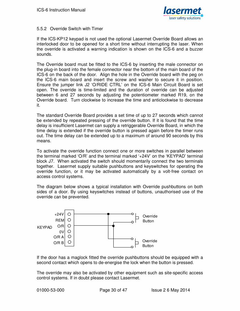
5.5.2 Override Switch with Timer If the ICS-KP12 keypad is not used the optional Lasermet Override Board allows an interlocked door to be opened for a short time without interrupting the laser. When the override is activated a warning indication is shown on the ICS-6 and a buzzer sounds. The Override board must be fitted to the ICS-6 by inserting the male connector on the plug-in board into the female connector near the bottom of the main board of the ICS-6 on the back of the door. Align the hole in the Override board with the peg on the ICS-6 main board and insert the screw and washer to secure it in position. Ensure the jumper link J2 ‘O/RIDE CTRL’ on the ICS-6 Main Circuit Board is set open. The override is time-limited and the duration of override can be adjusted between 6 and 27 seconds by adjusting the potentiometer marked R19, on the Override board. Turn clockwise to increase the time and anticlockwise to decrease it. The standard Override Board provides a set time of up to 27 seconds which cannot be extended by repeated pressing of the override button. If it is found that the time delay is insufficient Lasermet can supply a retriggerable Override Board, in which the time delay is extended if the override button is pressed again before the timer runs out. The time delay can be extended up to a maximum of around 90 seconds by this means. To activate the override function connect one or more switches in parallel between the terminal marked ‘O/R’ and the terminal marked ‘+24V’ on the ‘KEYPAD’ terminal block J7. When activated the switch should momentarily connect the two terminals together. Lasermet supply suitable pushbuttons and keyswitches for operating the override function, or it may be activated automatically by a volt-free contact on access control systems. The diagram below shows a typical installation with Override pushbuttons on both sides of a door. By using keyswitches instead of buttons, unauthorised use of the override can be prevented.
Override
Button
Override
Button
+24V
REM
O/R
0VKEYPAD
O/R A
O/R B
If the door has a maglock fitted the override pushbuttons should be equipped with a second contact which opens to de-energise the lock when the button is pressed. The override may also be activated by other equipment such as site-specific access control systems. If in doubt please contact Lasermet.

ICS-6 Instruction Manual
01000-53-000 Page 31 of 47 Issue 2 6 May 2014
5.5.3 Override Switch without Timer It is possible to configure the ICS-6 to give an unlimited override. This may be useful for maintenance purposes or when the access door may be open for some time. In general such an arrangement may require additional site procedures to ensure safety while the interlock is overridden. The override device may be a switch or other contact which remains closed for the duration of the override. A key-operated switch may be preferable to prevent unauthorised use. If a maglock is fitted to the door the override switch needs an additional contact which opens when activated, so that the lock is disabled allowing the door to be opened. The override control contact is wired as shown in the section ‘Override Switch with Timer’ above. The Lasermet Override Timer board is not fitted. The link ‘J6 Override Control’ is fitted to allow the override switch to directly control the override function. The buzzer may be unnecessarily annoying in this mode of operation so it may be disabled as shown in section 5.5.5. 5.5.4 Local Override Where there are several entrances to the laser enclosure it may be desirable for the override to be only applied to a particular entrance, such that the laser will be disarmed if another entrance is opened while the override is active. To achieve this, the overriding device needs to have two isolated contacts which close to bypass the safety contacts of the relevant door switch, and a third contact to activate the override indications on the ICS-6. If a maglock is fitted to the door the overriding device needs a fourth contact which opens when activated, so that the lock is disabled allowing the overridden door to be opened. The third contact is connected between the terminal marked ‘O/R’ and the terminal marked ‘+24V’ on the ‘KEYPAD’ terminal block J7. An Override Timer Board must not be fitted to the ICS-6, and the link ‘J6 Override Control’ must be removed to prevent the non-overidden door contacts from being defeated.

ICS-6 Instruction Manual
01000-53-000 Page 32 of 47 Issue 2 6 May 2014
5.5.5 Override Alarm There is an audible Override alarm inside the ICS-6 which is enabled when the BUZZER CTRL link J4 is closed on the main PCB. There is also an audible alarm on the Override board (if fitted) which is enabled by closing link 10. A red lamp illuminates on the front of the ICS-6 to indicate when the override is in operation.
ICS-6 Instruction Manual
01000-53-000 Page 33 of 47 Issue 2 6 May 2014
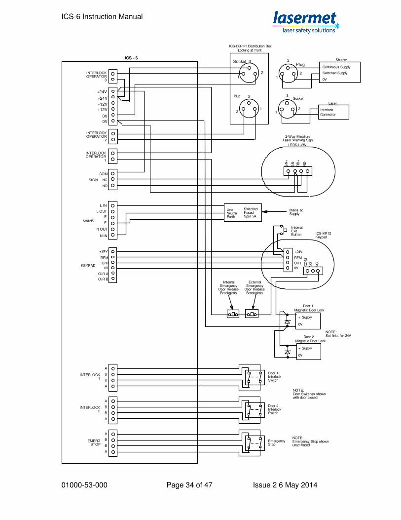
5.6 Typical Installation The diagram on the next page shows the full wiring of a typical installation using Lasermet equipment, with a set of interlocked double doors with magnetic door locks, control of one laser interlock and one shutter, two-way miniature warning sign and override to allow time-limited entry/exit by authorised persons.
ICS-6 Instruction Manual
01000-53-000 Page 34 of 47 Issue 2 6 May 2014
L IN
L OUT
E
E
N IN
N OUT
INTERLOCKOPERATOR
1
INTERLOCK2
EMERGSTOP
Emergency Stop
NOTE:Emergency Stop shownunactivated.
INTERLOCKOPERATOR
2
LiveNeutralEarth
SwitchedFusedSpur 5A
Mains acSupply
ICS - 6
+24V
REM
O/R
0VKEYPAD
+24V
REM
O/R
0V
CO
M
NO
NC
InternalExitButton ICS-KP12
Keypad
Magnetic Door Lock
+ Supply
0V
Magnetic Door Lock
+ Supply
0V
A
B
B
A
INTERLOCK1
Door 1InterlockSwitch
INTERLOCKOPERATOR
3
+24V
+24V
+12V
+12V
0V
0V
NOTE:Door Switches shownwith door closed.
NOTE:Set links for 24V
Shutter
Continuous Supply
Switched Supply
0V1
2
3
12
3Plug
Socket
Looking at front
Laser
Interlock
Connector
12
3
12
3Socket
ICS-DB-1/1 Distribution Box
Plug
O/R A
O/R BInternal
EmergencyDoor ReleaseBreakglass
ExternalEmergency
Door ReleaseBreakglass
A
B
B
A
Door 2InterlockSwitch
A
B
B
A
SIGN
NO
COM
NC
MAINS
RD
+
RD
-
GN
+
GN
-
LEDS-L-2W
2-Way MiniatureLaser Warning Sign
Door 1
Door 2

ICS-6 Instruction Manual
01000-53-000 Page 35 of 47 Issue 2 6 May 2014
6 Expansion Boards
6.1 Introduction The ICS-6 can accommodate one or more Lasermet Interlock Expansion Boards which provide extra functionality. Boards which are currently available include: Active Beamguard Interface Lasermet’s Active Beamguard system is intended to be used with lasers which are potentially capable of damaging or burning through their enclosures. The enclosure is lined with replaceable active detection tiles. If the laser burns through the tile it is shut down before it burns through the enclosure. The fail-safe Interface is able to monitor up to 1000 tiles and the ICS-6 is able to automatically test the operation of the tiles and the interface each time the system is armed. Safety Logic Plus Interface Safety Logic Plus consists of a range of fail-safe logic function blocks which can be hardwired to realise a complex safety interlock. Each block is dual-channel cross-checked and does not use processors or software. Programming is achieved through hardwiring. This means obsolescence is minimised and the system is maintainable for a long service life. The Interface Board allows ICS-6 to read the output of a Safety Logic Plus system whilst automatically testing it and providing fault protection. Network Communications Interface The Network Board allows the ICS-6 to be plugged into an ethernet network such that it may be monitored and optionally armed remotely. The Interface provides monitoring of the ICS-6 inputs so that the status of the ICS-6 and connected interlock signals may be monitored. Relay Expansion Card This module contains a number of uncommitted relays which may be connected as required to provide extra functionality or for interfacing to alarm, security or process control systems. Other types of expansion boards are under development.
6.2 Installing Expansion Boards It is possible to install one expansion board into a standard ICS-6, however the space for wiring is fairly restricted so a deep case option is available for ICS-6 which increases the depth of the unit from 89mm to 145mm, which gives ample space for three or four expansion boards.
ICS-6 Instruction Manual
01000-53-000 Page 36 of 47 Issue 2 6 May 2014
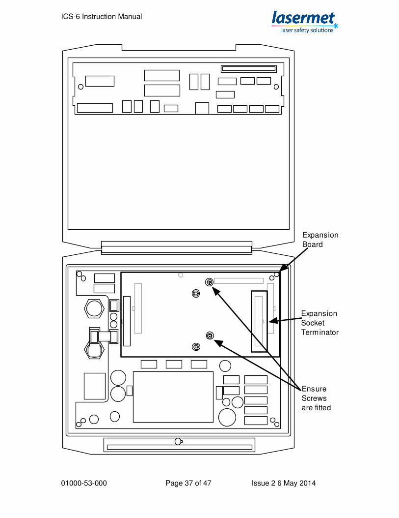
Note that the O-PCB override timer cannot be fitted at the same time as an expansion board. To fit an expansion board, turn off and isolate the mains supply and open the ICS-6. On the large circuit board on the inside of the ICS-6 cover, remove the ICS Expansion Control Socket Terminator near the top right corner. Do not discard it as it will be needed shortly. Locate the Expansion board onto the sockets on the large circuit board on the back of the door, such that the holes in the expansion board align with the screw pillars in the circuit board behind. It is most important that the holes are aligned with the pillars behind. Insert two M3 screws with shakeproof washers through the holes in the expansion board to secure it to the pillars. It is essential that the expansion board is fitted the right way round and secured with the screws as it may otherwise fall off, disabling the system. Refer to the diagram on the next page. Make the necessary electrical connections to the expansion board according to it’s specific instructions. If further expansion boards are required, fit each one on top of the previous one using the same method and ensuring that each is secured to the one below using the screws. It is usually easiest to wire each one before fitting the next one on top. Refit the ICS Expansion Control Socket Terminator to the socket in the top right corner on the topmost expansion board as shown on the next page.
ICS-6 Instruction Manual
01000-53-000 Page 37 of 47 Issue 2 6 May 2014
Expansion
Board
Ensure
Screws
are fitted
Expansion
Socket
Terminator
ICS-6 Instruction Manual
01000-53-000 Page 38 of 47 Issue 2 6 May 2014
7 Mismatch Detector
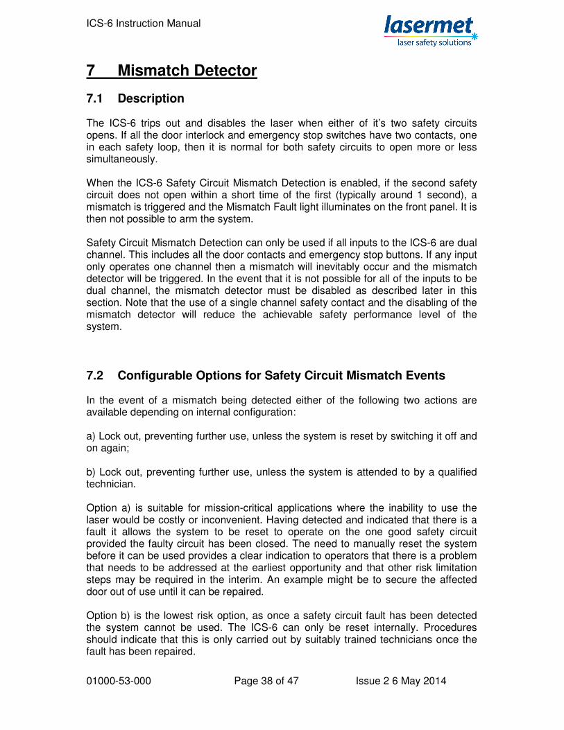
7.1 Description The ICS-6 trips out and disables the laser when either of it’s two safety circuits opens. If all the door interlock and emergency stop switches have two contacts, one in each safety loop, then it is normal for both safety circuits to open more or less simultaneously. When the ICS-6 Safety Circuit Mismatch Detection is enabled, if the second safety circuit does not open within a short time of the first (typically around 1 second), a mismatch is triggered and the Mismatch Fault light illuminates on the front panel. It is then not possible to arm the system. Safety Circuit Mismatch Detection can only be used if all inputs to the ICS-6 are dual channel. This includes all the door contacts and emergency stop buttons. If any input only operates one channel then a mismatch will inevitably occur and the mismatch detector will be triggered. In the event that it is not possible for all of the inputs to be dual channel, the mismatch detector must be disabled as described later in this section. Note that the use of a single channel safety contact and the disabling of the mismatch detector will reduce the achievable safety performance level of the system.
7.2 Configurable Options for Safety Circuit Mismatch Events In the event of a mismatch being detected either of the following two actions are available depending on internal configuration: a) Lock out, preventing further use, unless the system is reset by switching it off and on again; b) Lock out, preventing further use, unless the system is attended to by a qualified technician. Option a) is suitable for mission-critical applications where the inability to use the laser would be costly or inconvenient. Having detected and indicated that there is a fault it allows the system to be reset to operate on the one good safety circuit provided the faulty circuit has been closed. The need to manually reset the system before it can be used provides a clear indication to operators that there is a problem that needs to be addressed at the earliest opportunity and that other risk limitation steps may be required in the interim. An example might be to secure the affected door out of use until it can be repaired. Option b) is the lowest risk option, as once a safety circuit fault has been detected the system cannot be used. The ICS-6 can only be reset internally. Procedures should indicate that this is only carried out by suitably trained technicians once the fault has been repaired.

ICS-6 Instruction Manual
01000-53-000 Page 39 of 47 Issue 2 6 May 2014
To enable the Safety Circuit Mismatch Detection, remove the link Disable link ‘DIS’ J1 on the Control circuit board on the back of the ICS-6 door. To allow the detector to be reset by turning the power off and on again, fit the Auto-Reset link ‘AUTO RST’ J2. The power must be turned off for at least ten seconds for this to work.
Reset Header
Auto-Reset Link
Test Header
Disable Link
Reset Button
7.3 Clearing a Mismatch Fault Indication In all cases the fact that a Mismatch Fault has been indicated warns users that the safety of the system may be compromised. Site-specific instructions should indicate the actions to be taken by users in such an event. Depending on the internal settings made above, the system may or may not be temporarily cleared by turning the mains switch off, waiting for ten seconds, then turning it back on again. In this case the system should be attended to by a suitably qualified technician to identify and repair the fault at the earliest opportunity. If the ICS-6 has been configured to permanently lock out, it can only be reset by opening the unit, turning on the power and pressing the ‘RESET’ button SW1 on the Control Board. This should only be undertaken by suitably qualified technicians once the fault has been identified and repaired as otherwise the unit will just lock out again.

ICS-6 Instruction Manual
01000-53-000 Page 40 of 47 Issue 2 6 May 2014
7.4 Remote Test and Reset Headers are provided that allow for remote testing and resetting of the mismatch detector. For example, a key-operated switch could be connected to the headers so that when it is set one way it tests the mismatch detector, and when set the other way resets it. The key is then returned to the mid position and removed to allow normal operation to resume. The two headers are shown on the diagram above. For convenience, a single four-way 0.1” pitch connector can be connected across the two headers so that a four-core cable can be run to the remote switch unit. The ‘test’ switch should have a contact which is normally closed and which opens to perform the test. The ‘reset’ switch should have a contact which closes to reset the detector. Contact Lasermet or your local distributor for assistance if you wish to use these features.
ICS-6 Instruction Manual
01000-53-000 Page 41 of 47 Issue 2 6 May 2014
8 LED Indicators
8.1 'Interlock' LED’s Two LED’s are provided for each of the four Interlock Monitors. Each pair refers to an interlock switch or group of switches, depending on how the system has been wired up. For each Interlock, a pair of yellow LED’s indicate that the interlock is open. The left hand LED indicates the ‘A’ contact, the right hand LED indicates the ‘B’ contact. If the contact is not used and a wire link has been fitted, the corresponding LED will not illuminate. If both ‘A’ and ‘B’ contacts are fitted and it is observed that one LED is on and the other off, this indicates a fault which will be detected by the mismatch detector if it is enabled. In this event operation of the unit will be inhibited. Please see the ‘Mismatch Detector’ section.
8.2 ‘EXPN’ LED’s The ICS-6 may have one or more expansion boards fitted internally (see section 6), and the status of the board(s) is indicated. The LED’s are illuminated yellow if an expansion board has opened the ICS-6 safety circuits. The left hand LED indicates the ‘A’ contact, the right hand LED indicates the ‘B’ contact. The ICS-6 cannot be armed if either or both lights are lit. These lights will also be lit if the Expansion Socket Terminator has not been fitted as described in section 6. If an expansion board is fitted these lights will illuminate briefly when the system is armed, as the ICS-6 checks the operation of the expansion board.
8.3 'Safety Circuit Complete' LED’s These LED’s will light green when both safety circuits are complete. The system will not arm if either or both LED’s are unlit. This may be due to any of the following: a) The 'Enable' key switch is set to ‘Disable’.
b) A door interlock switch is open, indicated by the ‘Interlock’ lights on the front panel.
c) The emergency stop switch (if present) is activated, indicated by the ‘Emergency Stop’ lights on the front panel. Reset the switch to enable
ICS-6 Instruction Manual
01000-53-000 Page 42 of 47 Issue 2 6 May 2014
the system. d) The system has been disabled by a master control switch or other remote system. e) The expansion board, if fitted, is not ready, or the termination header
has not been fitted. f) The safety circuit is faulty.
8.4 Arm Button (illuminates blue) The Arm button will illuminate when both safety circuits are complete and all output devices are detected as being in the safe condition. This indicates that the ICS-6 is ready to be armed. If both Safety Circuit Complete lights are lit but the button is not illuminated, this indicates that one or more output devices are not detected in the safe condition. This may include:
a) An LS-20 shutter is missing or not closed, or a dummy plug has not been fitted to an empty LS-20 socket.
b) There is a problem associated with an expansion board, if fitted. c) There is a faulty relay or contactor, if they are fitted. d) If the laser has ‘laser safe’ proving contacts (see section 5.4.3), the laser is
not detected in the safe condition or is unplugged.
8.5 'Override On' LED When the override is in operation this LED will light red to warn that the interlocks are temporarily defeated.
8.6 ‘Mismatch Fault’ LED If the system is wired as a fully dual-channel system the Mismatch Detector is usually enabled as described in section 7. The ICS-6 continually monitors both safety circuits. If a mismatch occurs that lasts for more than about a second, the Mismatch Detector is triggered, which disables the system and illuminates a red ‘Mismatch Fault’ light on the front panel. Site-specific procedures may be applicable in such an event, which cover actions to be taken to determine the cause of the fault, to have it rectified and to restore the system to operation. There may also be procedures to allow operation in degraded mode until normal operation can be restored. Section 7 describes the mismatch detector and how it is reset.
ICS-6 Instruction Manual
01000-53-000 Page 43 of 47 Issue 2 6 May 2014
8.7 'Laser Armed' LED When the 'Safety Circuit Complete' LED has lit and the Arm Laser button has been pressed, the 'Laser Armed' LED will light orange to warn that the ICS-6 has enabled the laser. If the ‘Safety Circuit Complete’ LED is illuminated but the ‘Laser Armed’ LED does not illuminate when the Arm Laser button is pressed, this could indicate that the internal checking circuitry of the ICS-6 has detected a fault condition.
ICS-6 Instruction Manual
01000-53-000 Page 44 of 47 Issue 2 6 May 2014
9 Operation Once correctly wired the ICS-6 is extremely easy to use. The following instructions cover the most common arrangements. For more complex customer-specific systems additional procedures may apply.
9.1 Starting Up 1) Set the mains switch on the unit to ‘1’. 2) Insert the key into the interlock keyswitch and turn to the right, ‘Enable’. 3) Close all interlocked doors. The LED’s on the front panel will indicate yellow if the corresponding door is open. 4) Check any Emergency Stop buttons are released- if any have been pressed the Emergency Stop lights will illuminate yellow. 4) The 'Safety Circuit Complete' LED’s will light green and the Arm laser illuminates blue. 5) When you are ready to operate the laser, press the Arm Laser button. N.B. Be aware that this action restores power to the shutters or the laser, and may result in accessible laser beams, depending on your system set up. This button should only be pressed when everyone is ready and the necessary safety precuations have been taken e.g. protective eyewear etc.
9.2 Resuming Operation after an Interlock Switch has been opened
When any interlocked door is opened or the emergency stop button is activated, the ICS-6 will cut the power to the laser or the shutters. To resume laser operation: 1) Close all interlocked doors (where necessary). Note LED state on front panel. 2) Reset the emergency stop button (where necessary). 3) When ready to restart, press the ICS-6 Arm Laser button. N.B. Be aware that this action restores power to the shutters or the laser, and may result in accessible laser beams, depending on your system set up. This button should only be pressed when everyone is ready and the necessary safety precuations have been taken e.g. protective eyewear etc.

ICS-6 Instruction Manual
01000-53-000 Page 45 of 47 Issue 2 6 May 2014
9.3 Using The Override The override facility, where fitted, allows interlocked doors to be opened for a short time without the laser being interrupted. 1) To activate the override with a push button, simply press the button on the push-to-exit switch. The system will now go into override mode for a short time, and a buzzer will sound. N.B If any of the interlock switches are still open when the timed override expires, the ICS-6 will cut the power to the laser or shutters. 2) To activate the override externally with the use of an ICS-KP12 keypad simply type in the user 4 digit code ( default is 3333 ) the system will now go into override mode for typically about 15 seconds. If there is a magnetic lock on the door this will be released for typically 5 seconds. The access codes and times are may be adjusted by authorised persons by reference to the keypad instruction leaflet. N.B As with the push button if any of the interlock switches are still open when the timed override expires, the ICS-6 will cut the power to the laser or shutters. 3) If the override is activated by a keyswitch: a) Place the key in the override switch b) Turn the key. The timed override begins from this moment. The red LED will light on the ICS-6 panel, and the override alarm will sound. c) Remove the key. Any of the doors can now be opened without the laser or shutter power supply being interrupted. d) Close all doors before the timed override has finished.
ICS-6 Instruction Manual
01000-53-000 Page 46 of 47 Issue 2 6 May 2014
10 Specifications Safety Performance Upto PL’e’ to EN ISO 13849-1:2008 see section 3. Shutdown Time 6ms typical. Measured from opening of safety circuits to
opening of interlock operator contacts. Supply Voltage 96-264V ac 50-60Hz universal input. Power Consumption 15W typical (ICS-6 only). No. of Output Contacts 3 (standard) 9 (9-way upgrade option) Output Contact Rating 6A 240Vac / 50VDC resistive load (standard)
8A, two at 240Vac/50VDC, seven at 50V ac/dc (9-way option)
Ingress Protection IP50 Operating Conditions 0° to 55°C, 0% - 95% relative humidity non-condensing. Size 263mm wide X 233mm high X 89mm deep (standard)
263mm wide X 233mm high X 145mm deep (deep box) Weight 1.7kg (standard)

ICS-6 Instruction Manual
01000-53-000 Page 47 of 47 Issue 2 6 May 2014
11 Contact Details For sales and technical support: Lasermet Ltd. Lasermet House, 137 Hankinson Road, Bournemouth BH9 1HR United Kingdom. Tel.: +44 (0) 1202 770740 Fax: +44 (0) 1202 770730 E-mail: [email protected] Website: www.lasermet.com