Laser Systems and Applications - fisica.edu.uycris/teaching/lsa_Masoller_part2_2014_2015.pdf ·...
60
Laser Systems and Applications Cristina Masoller Research group on Dynamics, Nonlinear Optics and Lasers (DONLL) Departament de Física i Enginyeria Nuclear Universitat Politècnica de Catalunya [email protected] www.fisica.edu.uy/~cris MSc in Photonics & Europhotonics
-
Upload
truongtuyen -
Category
Documents
-
view
221 -
download
0
Transcript of Laser Systems and Applications - fisica.edu.uycris/teaching/lsa_Masoller_part2_2014_2015.pdf ·...

Laser Systems and Applications
Cristina Masoller Research group on Dynamics, Nonlinear Optics and Lasers (DONLL)
Departament de Física i Enginyeria Nuclear Universitat Politècnica de Catalunya
[email protected] www.fisica.edu.uy/~cris
MSc in Photonics & Europhotonics

Outline Block 1: Low power laser systems
Introduction
Photons in semiconductors
Semiconductor light sources
Models
Dynamical effects
Applications
SEMICONDUCTOR LIGHT SOURCES LEDS, AMPLIFIERS AND DIODE LASERS
10/12/2014 3

Outline
• Fabrication
• LI curve (efficiency, threshold)
• Characteristics (optical spectrum, thermal effects)
• Single-mode lasers
• Novel types of lasers
10/12/2014 4
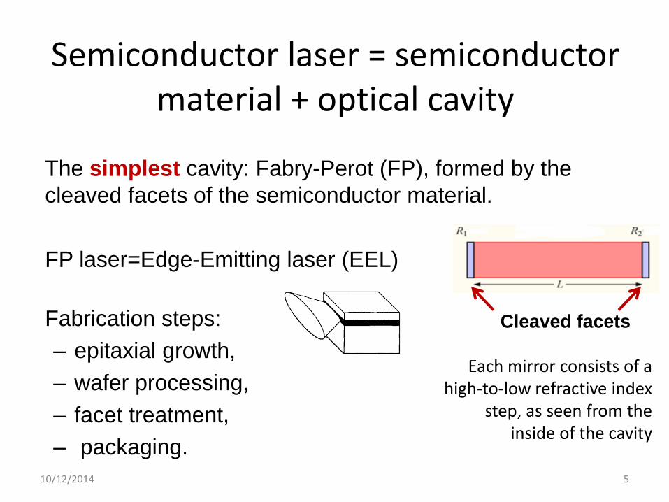
The simplest cavity: Fabry-Perot (FP), formed by the
cleaved facets of the semiconductor material.
FP laser=Edge-Emitting laser (EEL)
Fabrication steps:
– epitaxial growth,
– wafer processing,
– facet treatment,
– packaging.
10/12/2014 5
Semiconductor laser = semiconductor material + optical cavity
Cleaved facets
Each mirror consists of a high-to-low refractive index
step, as seen from the inside of the cavity
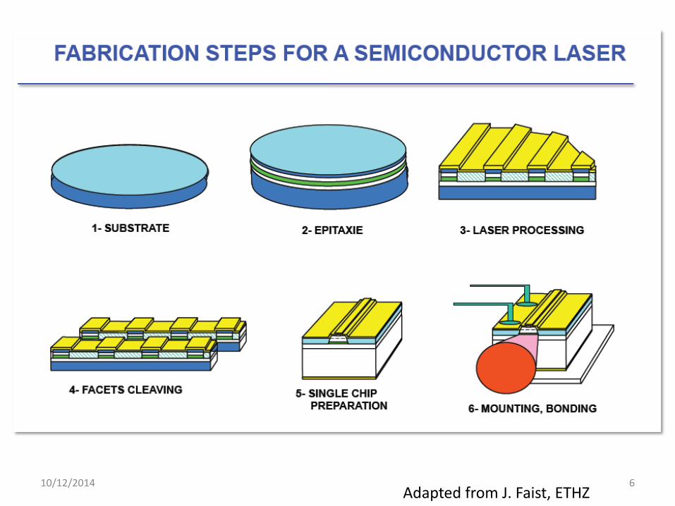
10/12/2014 6 Adapted from J. Faist, ETHZ
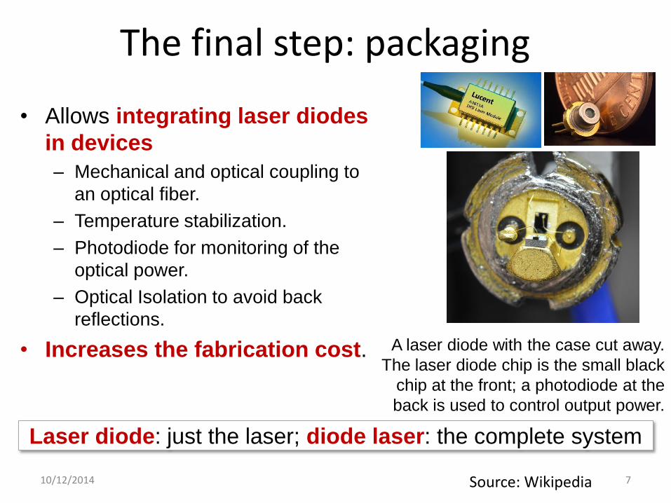
The final step: packaging
• Allows integrating laser diodes
in devices
– Mechanical and optical coupling to
an optical fiber.
– Temperature stabilization.
– Photodiode for monitoring of the
optical power.
– Optical Isolation to avoid back
reflections.
• Increases the fabrication cost.
10/12/2014 7
A laser diode with the case cut away.
The laser diode chip is the small black
chip at the front; a photodiode at the
back is used to control output power.
Source: Wikipedia
Laser diode: just the laser; diode laser: the complete system

Diode lasers vs LEDs
10/12/2014 8
Diode laser LED
Note the different scales

Resonator losses and optical confinement factor
10/12/2014 9
r = i - ln(R1R2)/2L
Laser threshold condition: net gain = losses (mirror + other) the laser
threshold is above transparency.
Losses caused by optical spread are accounted for, phenomenologically,
by the optical confinement factor < 1 that either increases the losses or
reduces the net gain:
= r/
a = p (gain coefficient)
i represents other sources of loss (the absorption in the
semiconductor material is accounted for by the net gain coefficient)
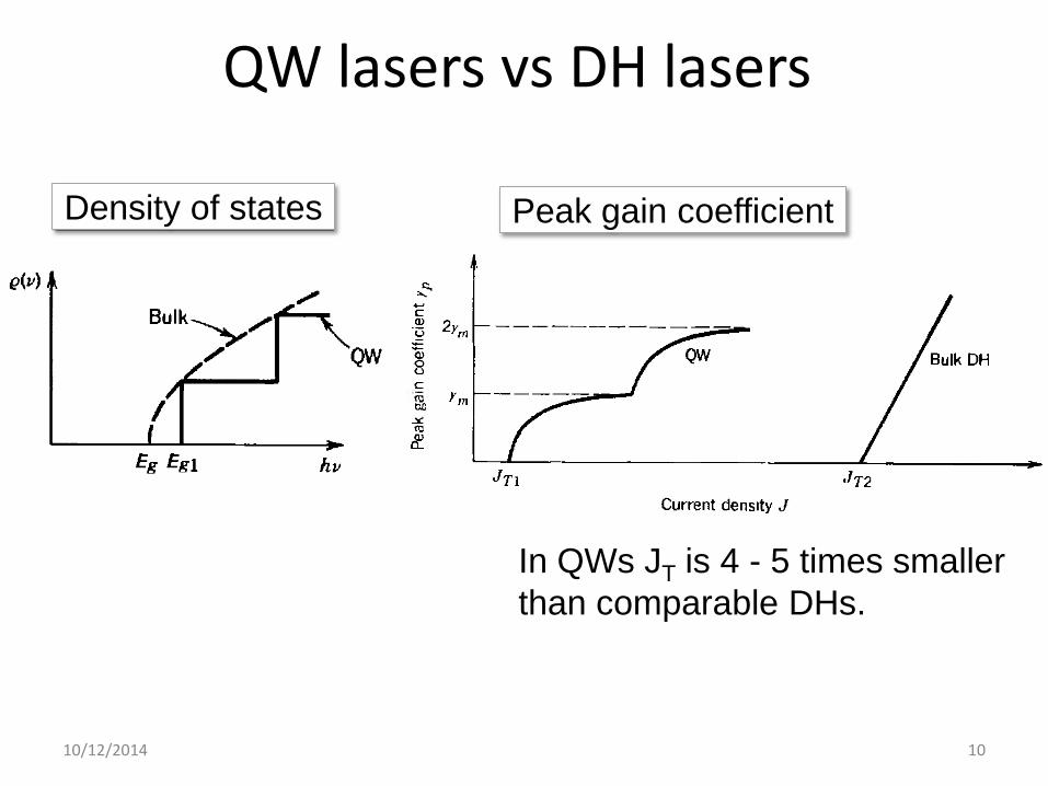
QW lasers vs DH lasers
Density of states
10/12/2014 10
Peak gain coefficient
In QWs JT is 4 - 5 times smaller
than comparable DHs.

Quantum dot lasers (QDLs)
• While QWs are thin layers of semiconductor material,
quantum dots are (as the name suggests), dots or islands of
a material surrounded by another material.
• The dots have a lower-energy bandgap than the surrounding
material.
• The lasing wavelength is determined by the size and shape
of the QDs.
• By controlling the size and shape of the QDs, QDLs can
span a large range of wavelengths.
10/12/2014 11
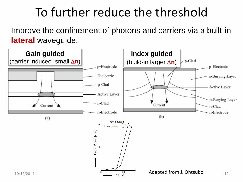
To further reduce the threshold
10/12/2014 12 Adapted from J. Ohtsubo
Gain guided (carrier induced small n)
Index guided
(build-in larger n)
Improve the confinement of photons and carriers via a built-in
lateral waveguide.

The lasing threshold: a long way from the beginning
10/12/2014 13 Adapted from H. Jäckel, ETHZ
4 orders of
magnitude
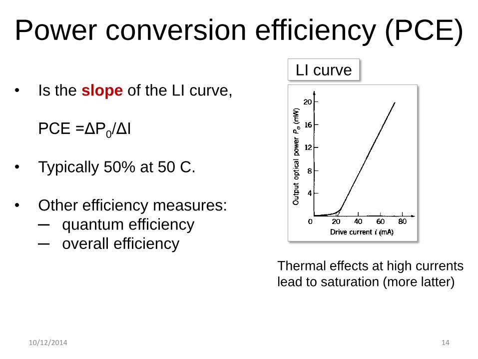
Power conversion efficiency (PCE)
10/12/2014 14
• Is the slope of the LI curve,
PCE =ΔP0/ΔI
• Typically 50% at 50 C.
• Other efficiency measures:
─ quantum efficiency
─ overall efficiency
LI curve
Thermal effects at high currents
lead to saturation (more latter)

Quantum efficiency • Laser optical power: P= h (in Watts)
: flux of emitted photons (photons per unit time).
• = d (I-Ith)/e (I, Ith in amperes)
d : quantum efficiency. It accounts for the fact that only a
fraction of the electron-hole recombinations are radiative
(internal efficiency) + only part of the emitted photons are
useful (emission efficiency)
P = h d (I-Ith)/e =1.24 d (I-Ith)/
10/12/2014 15
Example:
• Ith= 21 mA
• =1.3 m (InGaAsP)
• d =( /1.24) P/(I-Ith)=0.4

Overall efficiency
• Ratio optical power to electrical power, = P/IV
• P = (h/e) d (I-Ith)
• V = Vk + RdI
Vk is the kink voltage (related to the separation of quasi-
Fermi energies)
Rd = dV/dI is the differential resistance
• = (h/e) d (I-Ith) /I(Vk + RdI)
• The efficiency is maximum when the injected current is
10/12/2014 16

Optical spectrum: how many modes?
10/12/2014 17
(free-space wavelength
spacing, measured with an
Optical Spectrum Analyzer)
n = 3.5, L = 1 mm:
Δλ = 0.05 nm @ 635 nm
Δλ = 0.3 nm @ 1550 nm
Δ = c/(2nL)
Δλ = (λo)2/(2nL)
m = m (c/n)/(2L)
(mirrors)
• The semiconductor gain spectrum is broad
supports many longitudinal modes.
Exercise
10/12/2014 18
Consider a InGaAsP (n=3.5) laser with a FP cavity of length
L = 400 m. If the gain spectral width is 1.2 THz, how many
longitudinal modes may oscillate? If the central wavelength is
1.3 m, which is the wavelength spacing?

10/12/2014 19
Gain + cavity determine the optical spectrum
• The number of lasing
modes and their
relative power depends
on gain (current and
temperature) and on
the type of laser.
• It is often possible to
adjust I and T for
single-mode operation,
but it can be achieved
over a limited I and T
range.
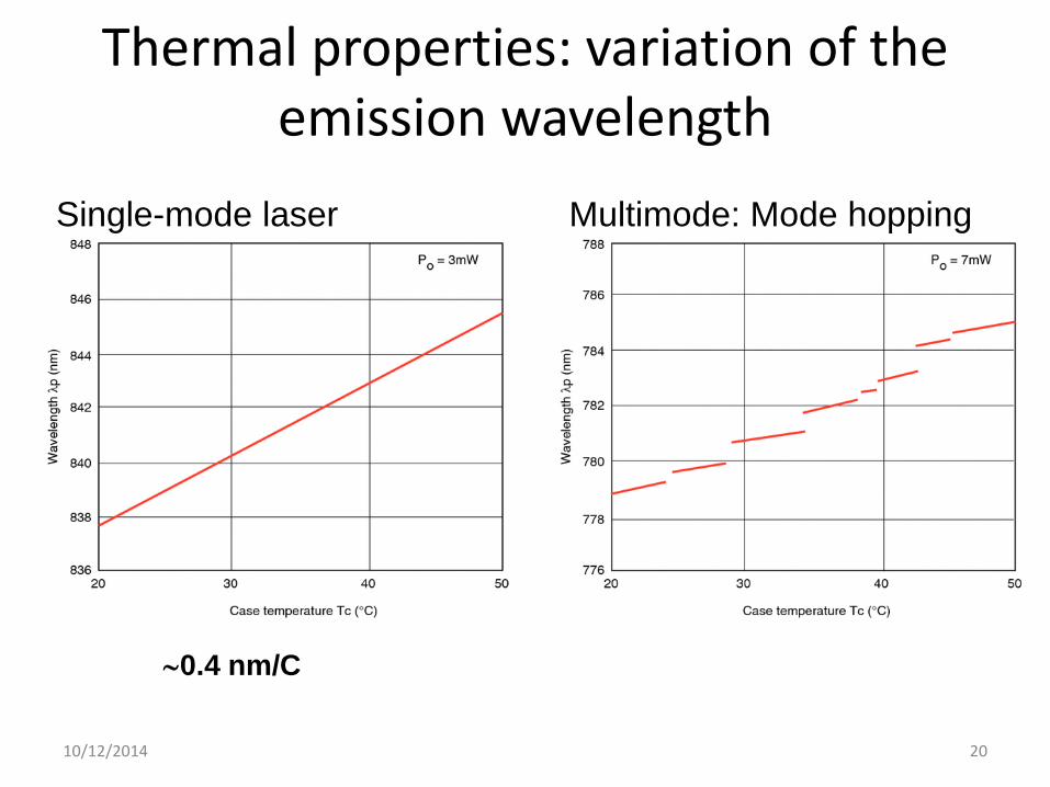
Thermal properties: variation of the emission wavelength
10/12/2014 20
Multimode: Mode hopping Single-mode laser
0.4 nm/C

Thermal effects in the LI curve
10/12/2014 21
Thermal variation of threshold current
Thermal
saturation
Why?
10/12/2014 22
With increasing current, increasing temperature (Joule
heating).
Temperature affects:
• the gain (the peak and the width)
• the refractive index
Kramers-Kronig: gain ─ Im(), n Re()
The temperature modifies n which in turn modifies the
cavity resonance.
Compensation: engineered gain off-set

Single-mode emission is important
Low power lasers:
• High-data-rate optical fiber transmission requires lasers that
emit single mode.
• This is because each mode travels with its own group velocity.
Optical pulses emitted by a multimode laser broaden with
propagation distance (and the distinction between 'zero' and
'one' is gradually lost).
High power lasers:
• Single-mode emission is needed in applications that require
high-quality beam (multimode emission results in low beam
quality).
10/12/2014 23
Can we fabricate single-mode lasers?
Dynamically stable?
Yes! By using a mode-selective cavity
• An External mirror – External Cavity Laser (ECL)
• A Bragg-Grating (BG) mirror
– Distributed Feedback (DFB)
– Distributed Bragg Reflector (DBR)
– Vertical Cavity Surface Emitting Lasers (VCSEL)
10/12/2014 24

External Cavity Laser
10/12/2014 25
• With controlled feedback conditions the laser emission
“locks” to one of the modes of the “compound” cavity.
Advantage: decrease of the threshold current (reduced
cavity loss) and reduced line-width.
• Drawback: uncontrolled feedback conditions can lead to
instabilities and chaotic output (more latter).
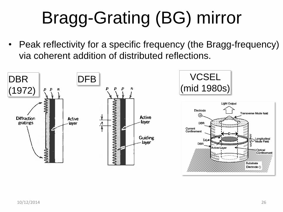
Bragg-Grating (BG) mirror
10/12/2014 26
DBR
(1972)
DFB
• Peak reflectivity for a specific frequency (the Bragg-frequency)
via coherent addition of distributed reflections.
VCSEL
(mid 1980s)
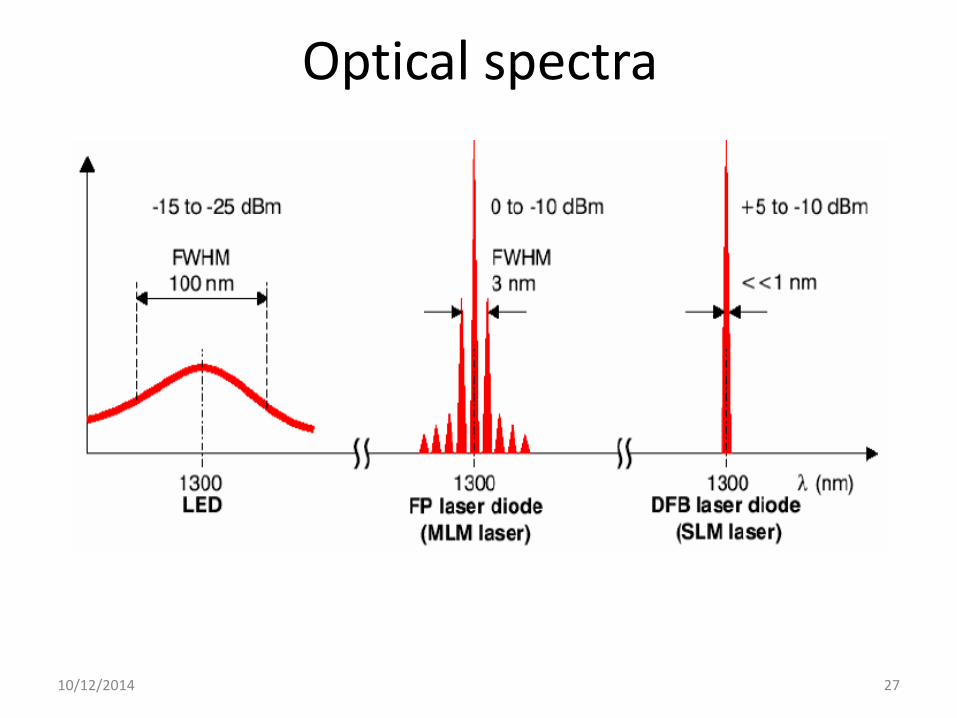
Optical spectra
10/12/2014 27
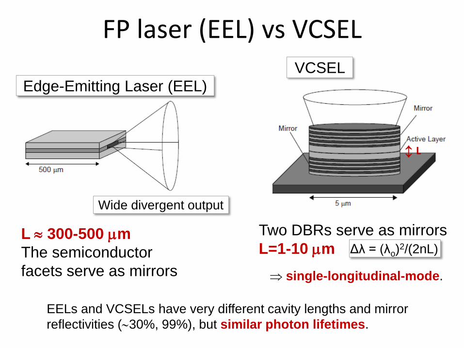
FP laser (EEL) vs VCSEL
L 300-500 m
The semiconductor
facets serve as mirrors
Two DBRs serve as mirrors
L=1-10 m
Edge-Emitting Laser (EEL)
VCSEL
Wide divergent output
Δλ = (λo)2/(2nL)
EELs and VCSELs have very different cavity lengths and mirror
reflectivities (30%, 99%), but similar photon lifetimes.
single-longitudinal-mode.
L
Exercise
10/12/2014 29
InGaAsP (n=3.5) VCSEL laser with L = 5 m. If the gain
spectral width is 1.2 THz, how many longitudinal modes may
oscillate? If the DBRs reflectivity is 99%, what is the photon
lifetime? Compare with an EEL of L = 400 m.
VCSELs
• First demonstrated by K. Iga et al. in late 70s, cw operation in late 80s.
• VCSELs nowadays used in optical computer mouse (but also LEDs). The
low power consumption of VCSELs is attractive for cordless, battery-
driven mice.
• VCSELs have replaced EELs for use in multimode fiber-based Gbit/s
speed optical data transmission for the interconnection of data centers
and computer clusters.
• Arrays of individually addressable VCSELs are used in laser printers, to
simultaneously improve resolution and speed.
• Early GaAs-based VCSELs (850 nm) used metal and dielectric mirrors.
• Next development: full monolithic InGaAs–GaAs lasers (960 nm)
incorporating epitaxial distributed Bragg reflectors (DBRs).
• The production volume nowadays is about 100 million lasers per year.
C. Masoller, LSA 2013 30
Advantages
• single-longitudinal-mode emission
• low threshold currents (< 1mA), high efficiency (> 50%)
• circular beam profiles with small divergence angles, simplifying the design
of beam-shaping optics.
• Wide temperature operation (+125◦C); long lifetimes (>106 hours at RT).
• High data transmission speed (850 nm, 40 Gbit/s up to 80 C –Sep. 2014).
• The active diameter of the VCSEL can be reduced to just a few μms in
order to obtain single-transverse-mode operation together with lowest
threshold currents in the sub-100 μA range.
• It can also exceed 100 μm to get high output powers beyond 100 mW.
• Can be designed for continuous wavelength tuning for gas sensing
applications.
• Device testing at the wafer level, reducing fabrication cost.
• Straightforward fabrication of homogeneous 1D and 2D laser arrays for
compact space division multiplexed data transmission,
31
10/12/2014 32

The cost of manufacturing optics
10/12/2014 33 Source: OPN Oct. 2014
In absolute terms, however, wafer fabrication costs just as
much for integrated photonics as for conventional
electronics—the high cost of assembly is in addition to that.
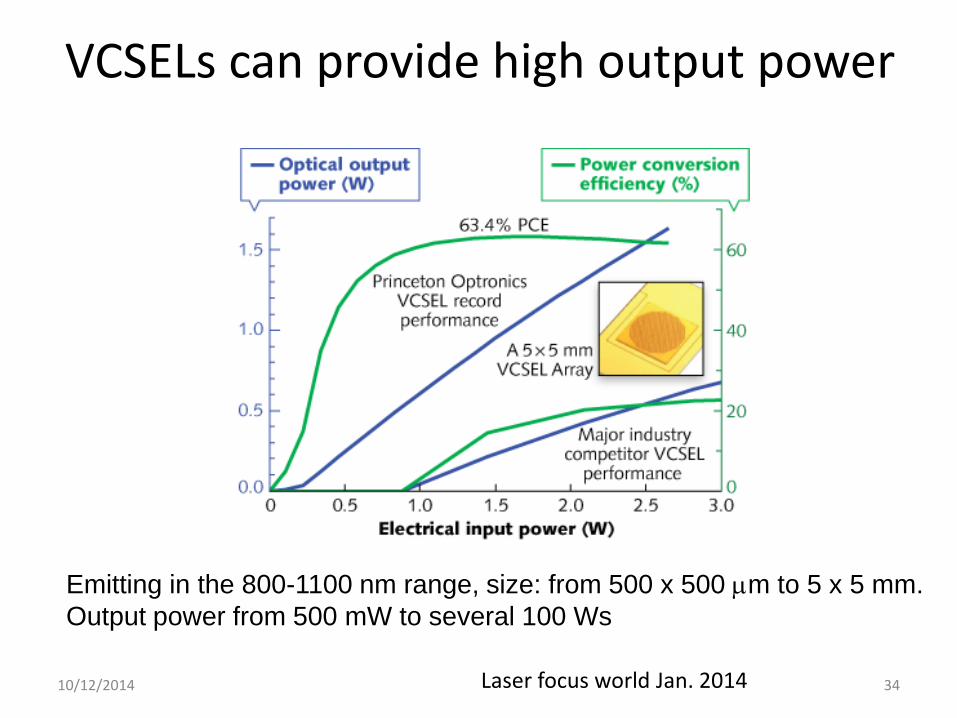
10/12/2014 34 Laser focus world Jan. 2014
Emitting in the 800-1100 nm range, size: from 500 x 500 m to 5 x 5 mm.
Output power from 500 mW to several 100 Ws
VCSELs can provide high output power

Scalability
10/12/2014 35
Chip with an array of
thousands of
VCSELs
Building blocks of increasing power and size.
Submodule with 12 x 14
chips on sub-mounts on
a micro-channel cooler
System of 3.5 kW
consisting of 24
sub-modules.
Kolb et al 2013

10/12/2014 36
Lateral/transverse modes
Edge-Emitting Lasers: VCSELs:
• The circular
profile allows
easy coupling to
an optical fiber.
• But single-
transverse mode
emission limited
to few mW.
Solutions of the
Helmholz equation
Adapted from A. Larsson, JSTQE 2011
Fundamental mode operation can be achieved by
matching the mode area to the active gain area.

Complex transverse patterns
10/12/2014 37
Near-field intensity distributions at different injection currents (9 mA 15
mA 20 mA and 25 mA).
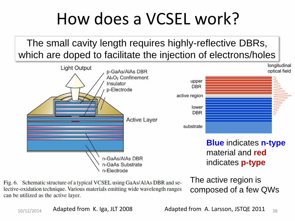
How does a VCSEL work?
10/12/2014 38 Adapted from K. Iga, JLT 2008
Blue indicates n-type
material and red
indicates p-type
Adapted from A. Larsson, JSTQE 2011
The small cavity length requires highly-reflective DBRs,
which are doped to facilitate the injection of electrons/holes
The active region is
composed of a few QWs
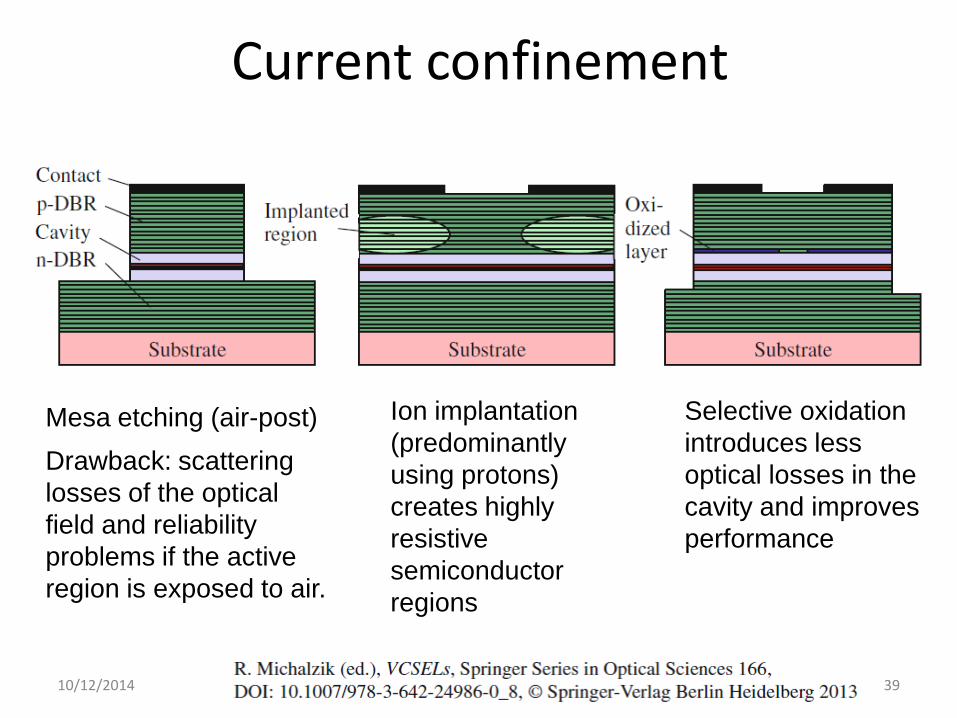
Current confinement
Mesa etching (air-post)
Drawback: scattering
losses of the optical
field and reliability
problems if the active
region is exposed to air.
10/12/2014 39
Selective oxidation
introduces less
optical losses in the
cavity and improves
performance
Ion implantation
(predominantly
using protons)
creates highly
resistive
semiconductor
regions
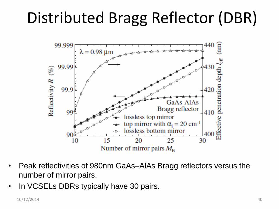
Distributed Bragg Reflector (DBR)
• Peak reflectivities of 980nm GaAs–AlAs Bragg reflectors versus the
number of mirror pairs.
• In VCSELs DBRs typically have 30 pairs.
10/12/2014 40

DBR reflectivity vs wavelength
10/12/2014 41
• Intensity reflection coefficient R and the phase of the
amplitude reflection coefficient vs (MB =16).
• The outer left-hand ordinate presents details in the center,
revealing substantial curvature of R(λ)

Combined effect of two DBRs
• 980nm VCSEL with 16 top and
22.5 bottom GaAs–AlAs Bragg
mirror pairs.
10/12/2014 42
Cavity resonance
• Optical mode.
DBRs drawbacks for long wavelength VCSELs
• GaAs-based devices benefit from a large index difference
between GaAs and AlAs that allows to fabricate high-
reflective Bragg mirrors even with small numbers of layers.
• Long-wavelength VCSELs based on InP suffer from almost
a factor of two smaller index contrast of the InGaAsP or
InGaAlAs mirror layers. Thus, larger numbers of layer pairs
are required for reasonable mirror reflectivity.
• Also a problem: larger layer thicknesses (due to the longer
wavelength), the epitaxial mirror stacks of the InP-based
VCSELs become rather thick.
• Also a problem: heat due to the high thermal resistance of
DBRs.
10/12/2014 43
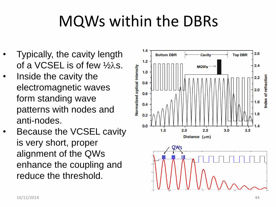
MQWs within the DBRs
10/12/2014 44
• Typically, the cavity length
of a VCSEL is of few ½s.
• Inside the cavity the
electromagnetic waves
form standing wave
patterns with nodes and
anti-nodes.
• Because the VCSEL cavity
is very short, proper
alignment of the QWs
enhance the coupling and
reduce the threshold.
QWs
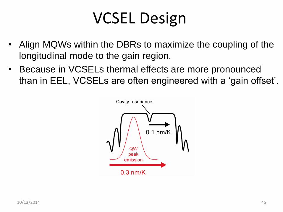
VCSEL Design
• Align MQWs within the DBRs to maximize the coupling of the
longitudinal mode to the gain region.
• Because in VCSELs thermal effects are more pronounced
than in EEL, VCSELs are often engineered with a ‘gain offset’.
10/12/2014 45

Alternative solution: MEMs (micro-electro-mechanical systems)
10/12/2014 46 Adapted from K. Iga, JLT 2008
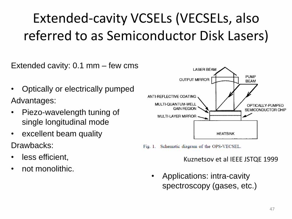
Extended-cavity VCSELs (VECSELs, also referred to as Semiconductor Disk Lasers)
Extended cavity: 0.1 mm – few cms
• Optically or electrically pumped
Advantages:
• Piezo-wavelength tuning of
single longitudinal mode
• excellent beam quality
Drawbacks:
• less efficient,
• not monolithic.
47
Kuznetsov et al IEEE JSTQE 1999
• Applications: intra-cavity
spectroscopy (gases, etc.)

10/12/2014 48
Another type of cavity: Ring
• “whispering-gallery” modes, discovered by Raman in
1920 while visiting London Cathedral.
OPN July 2013

10/12/2014 49 Adapted from Sorel et al, JQE 2003
Semiconductor ring lasers Two “whispering-gallery” modes

10/12/2014 50
• Like a whispering gallery mode, the light
propagates around the edges of the
pillars, but in a helix rather than a circle.
• Although light propagating downward is
absorbed by the substrate, there was
enough gain in the upward propagating
light to provide lasing.
• The semiconductor cavity mode alone
provides enough confinement (no need
of metal cavity).
• sub-wavelength lasing: the pillars are
smaller on a side than the wavelength
they emit.
See also OPN May 2011

10/12/2014 51
Optically pumped by using a mode-locked Ti:sapphire laser
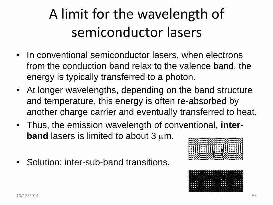
A limit for the wavelength of semiconductor lasers
• In conventional semiconductor lasers, when electrons
from the conduction band relax to the valence band, the
energy is typically transferred to a photon.
• At longer wavelengths, depending on the band structure
and temperature, this energy is often re-absorbed by
another charge carrier and eventually transferred to heat.
• Thus, the emission wavelength of conventional, inter-
band lasers is limited to about 3 m.
• Solution: inter-sub-band transitions.
10/12/2014 52

10/12/2014 53
Cascade: one electron
generates many photons

10/12/2014 54
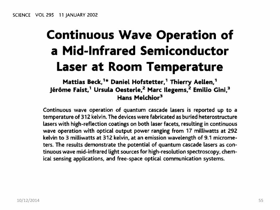
10/12/2014 55
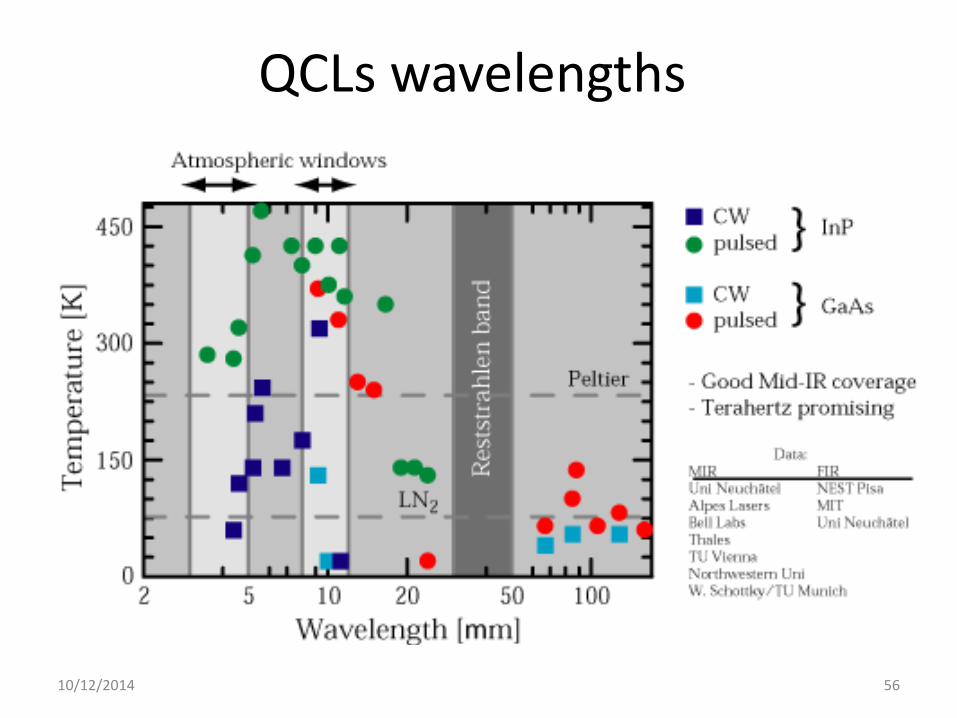
QCLs wavelengths
10/12/2014 56

10/12/2014 57
Optics and Photonics News, July/August 2008
QCLs applications

Summarizing, the design goals of semiconductor light sources are
To optimize carrier injection properties
To optimize optical confinement
To minimize optical loss and heating
To obtain maximum gain at a given injection power
To obtain high-quality spatial profile and spectral purity
To cover a wide range of wavelengths
10/12/2014 58

TF test In EELs the Fabry-Perot cavity is formed by the cleaved facets of
the semiconductor material.
EELs and VCSELs have active regions of comparable sizes.
Bragg-Grating lasers (DFBs and DBRs) emit a multimode
spectrum.
The goal of diode laser design is to improve the confinement of
photons and carriers, which allows lowering the threshold current.
The threshold of diode lasers and amplifiers is at transparency,
when the rate of stimulated emission is equal to absorption.
Thermal heating is responsible for the saturation of the LI curve and
the shift of the emission wavelength with increasing current.
Bulk lasers are as efficient as QW lasers.
Quantum cascade lasers operate on inter-sub-band transitions.
10/12/2014 59
THANK YOU FOR YOUR ATTENTION !
Universitat Politecnica de Catalunya
http://www.fisica.edu.uy/~cris/