Laser Speckle Extensometer ME53 - MESSPHYSIK · Laser Speckle Extensometer ME53 ALTENMARKT 180,...
16
Laser Speckle Extensometer ME53 ALTENMARKT 180, 8280 FÜRSTENFELD TEL.: +43 3382-54060-0 FAX: -27 AUSTRIA, EUROPE WWW.MESSPHYSIK.COM PDS 161 J en
Transcript of Laser Speckle Extensometer ME53 - MESSPHYSIK · Laser Speckle Extensometer ME53 ALTENMARKT 180,...
Laser Speckle Extensometer
ME53
ALTENMARKT 180, 8280 FÜRSTENFELDTEL.: +43 3382-54060-0 FAX: -27
AUSTRIA, EUROPEWWW.MESSPHYSIK.COM
PDS 161 J en
- 2 -
INTRODUCTION
When establishing the mechanical properties of today’s diverse range of materials and components it isnecessary to use accurate testing machines and instrumentation that do not influence the results.
Stress and strain are the two main parameters from which most mechanical properties are calculatedduring uniaxial testing. Stress is normally obtained by fixing a test specimen in grips or adapters andloading via a calibrated load cell. Care must be taken to ensure that neither the fixation method, noralignment, nor specimen shape influence the results obtained.
For rigid materials, strain can be measured using conventional ‘clip-on’ mechanical extensometers or bybonding foil gauges to the specimen. These devices however are not usually suitable when testing delicatespecimens such as fibres, films, foils, foams or soft plastics as their weight and method of attachment caninfluence both the results obtained and the point of rupture.
In many instances it is necessary to establish the material properties over large strain ranges up to thepoint of rupture and most mechanical devices have a limited travel and require removal from the specimenprior to fracture. If a specimen is to be tested at elevated temperature within a confined chamber, then thiscan restrict the use of many mechanical units.
Various non-contacting extension measuring systems e.g. mechanically driven followers and laserextensometers have been available over latter years, but these systems do not have the necessaryresolution to accurately determine the material properties at low strain levels. Also as the devices operateon a single measuring line between targets a second unit would be required if the transverse strain had tobe simultaneously measured.
In order to overcome these limitations, the ME-53 Laser Speckle Extensometer was developed by theAustrian company Messphysik GmbH, on the basis that “If it can be seen, then it can be measured”. It's aneasy to use class 1 measurement system, having the capability to measure very small strains and highstrains, completely contact-free.
This enables the usage in a wide range of applications, including applications using elevatedtemperatures.
- 3 -
MEASUREMENT PRINCIPLE
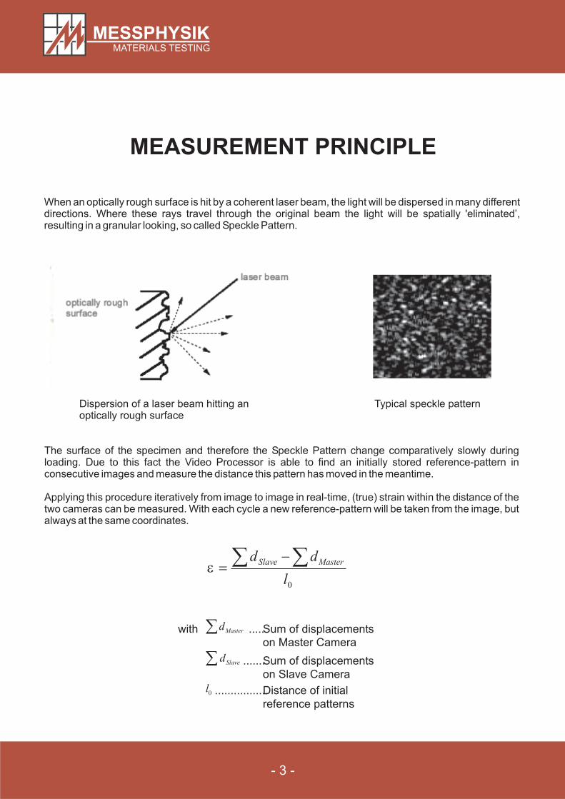
0l
dd MasterSlave �� ���
with .....Sum of displacements
on Master Camera
.......Sum of displacements
on Slave Camera
.................Distance of initial
reference patterns
� Masterd
� Slaved
0l
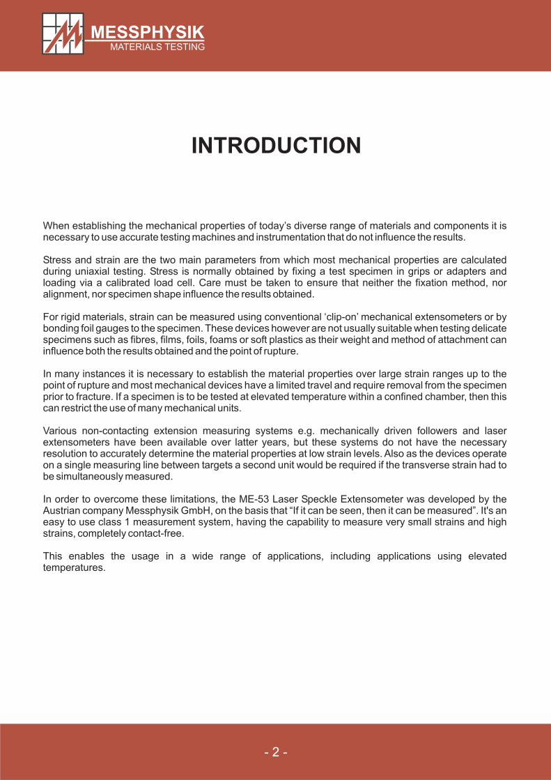
When an optically rough surface is hit by a coherent laser beam, the light will be dispersed in many differentdirections. Where these rays travel through the original beam the light will be spatially 'eliminated’,resulting in a granular looking, so called Speckle Pattern.
The surface of the specimen and therefore the Speckle Pattern change comparatively slowly duringloading. Due to this fact the Video Processor is able to find an initially stored reference-pattern inconsecutive images and measure the distance this pattern has moved in the meantime.
Applying this procedure iteratively from image to image in real-time, (true) strain within the distance of thetwo cameras can be measured. With each cycle a new reference-pattern will be taken from the image, butalways at the same coordinates.
Dispersion of a laser beam hitting anoptically rough surface
Typical speckle pattern
The fundamental task of the Laser Speckle Extensometer’s software is to recognize a complex pattern (i.e.region of the video image) in consecutive images. To accomplish these highly intensive calculations state-of-the-art computers are used for Video Processors on one hand and carefully programmed algorithmsemployed on the other hand. First the analogue video images have to be transformed into digital images bymeans of a so called Frame Grabber. Built into the Video Processor this special hardware translates thevideo signal into a two-dimensional matrix with 756x576 elements (pixels) with 256 grey shades each at arate of 25 frames per second. But it is neither necessary nor possible to analyse the entire video image inreal-time a region of variable position and size is sufficient enough.
These regions also function as virtual markers, between which strain is measured as explained earlier.This involves the calculation of the displacements of these markers from frame to frame.
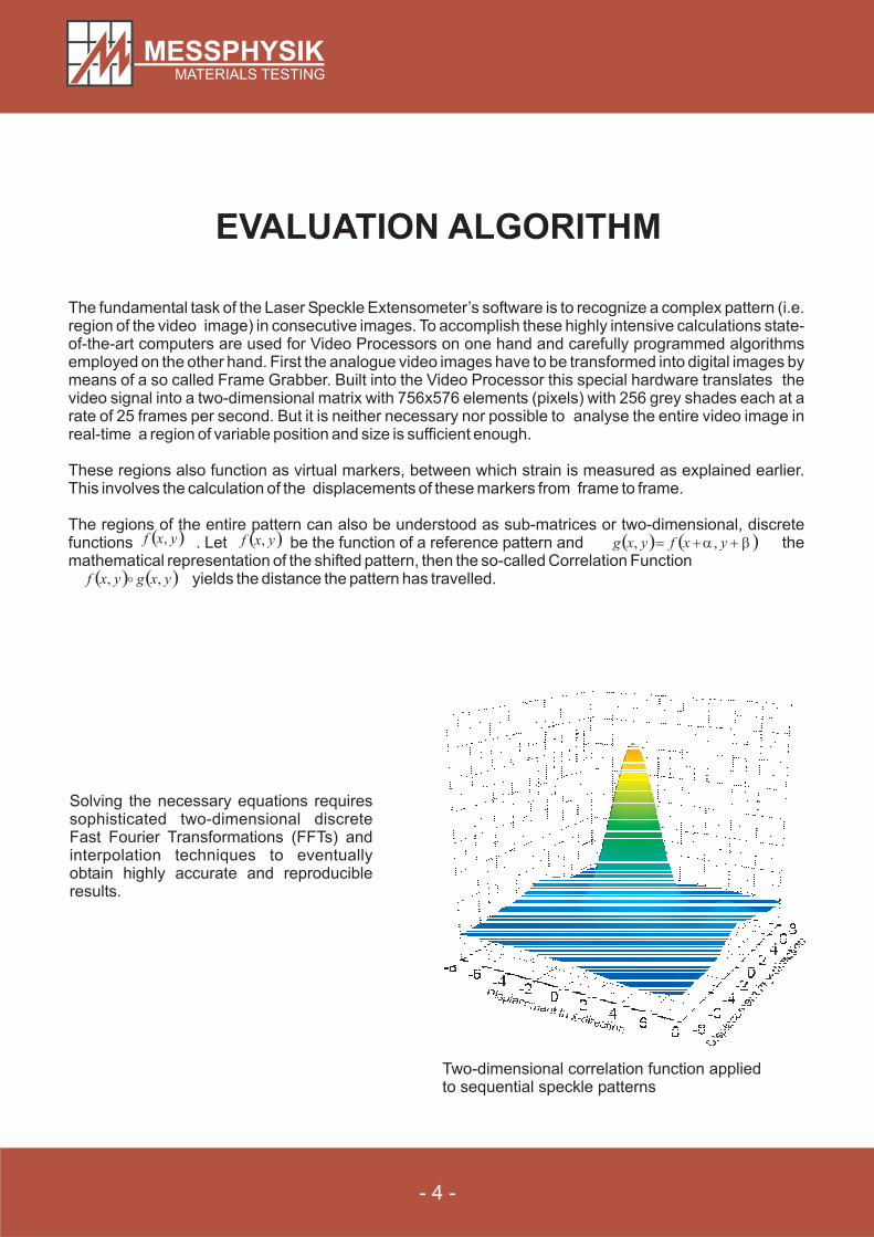
The regions of the entire pattern can also be understood as sub-matrices or two-dimensional, discretefunctions . Let be the function of a reference pattern and themathematical representation of the shifted pattern, then the so-called Correlation Function
yields the distance the pattern has travelled.
- 4 -
EVALUATION ALGORITHM
� �yxf , � �yxf , � � � ��� � yxfyxg ,,
� � � �yxgyxf ,, �
Solving the necessary equations requiressophisticated two-dimensional discreteFast Fourier Transformations (FFTs) andinterpolation techniques to eventuallyobtain highly accurate and reproducibleresults.
Two-dimensional correlation function appliedto sequential speckle patterns
- 5 -
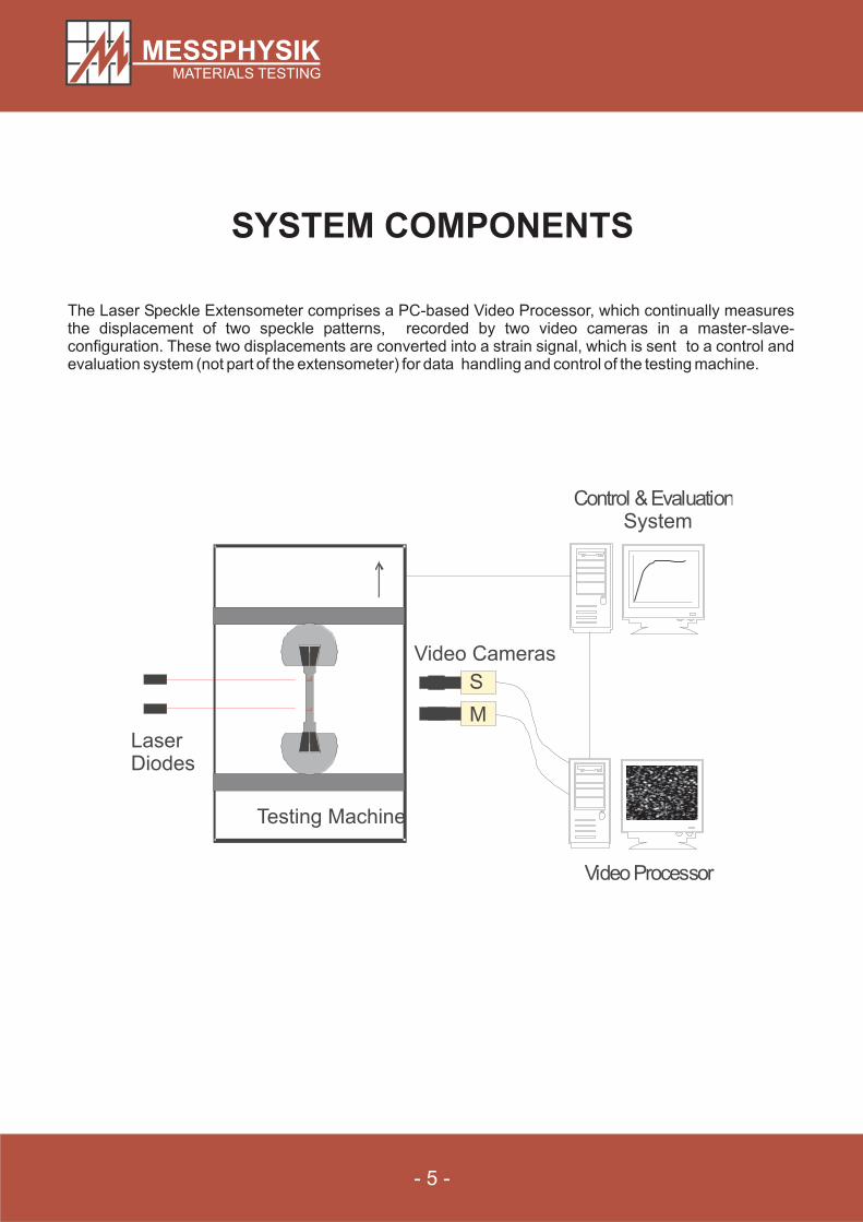
SYSTEM COMPONENTS
M
S
Testing Machine
LaserDiodes
System
Video Cameras
The Laser Speckle Extensometer comprises a PC-based Video Processor, which continually measuresthe displacement of two speckle patterns, recorded by two video cameras in a master-slave-configuration. These two displacements are converted into a strain signal, which is sent to a control andevaluation system (not part of the extensometer) for data handling and control of the testing machine.
- 6 -
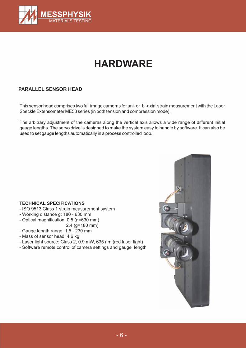
PARALLEL SENSOR HEAD
HARDWARE
TECHNICAL SPECIFICATIONS
-- ISO 9513 Class 1 strain measurement system
Working distance g: 180 - 630 mm
- Optical magnification: 0.5 (g=630 mm)
2.4 (g=180 mm)
- Gauge length range: 1.5 - 230 mm
- Mass of sensor head: 4.6 kg
- Laser light source: Class 2, 0.9 mW, 635 nm (red laser light)
- Software remote control of camera settings and gauge length
This sensor head comprises two full image cameras for uni- or bi-axial strain measurement with the Laser
Speckle Extensometer ME53 series (in both tension and compression mode).
The arbitrary adjustment of the cameras along the vertical axis allows a wide range of different initial
gauge lengths. The servo drive is designed to make the system easy to handle by software. It can also be
used to set gauge lengths automatically in a process controlled loop.
- 7 -
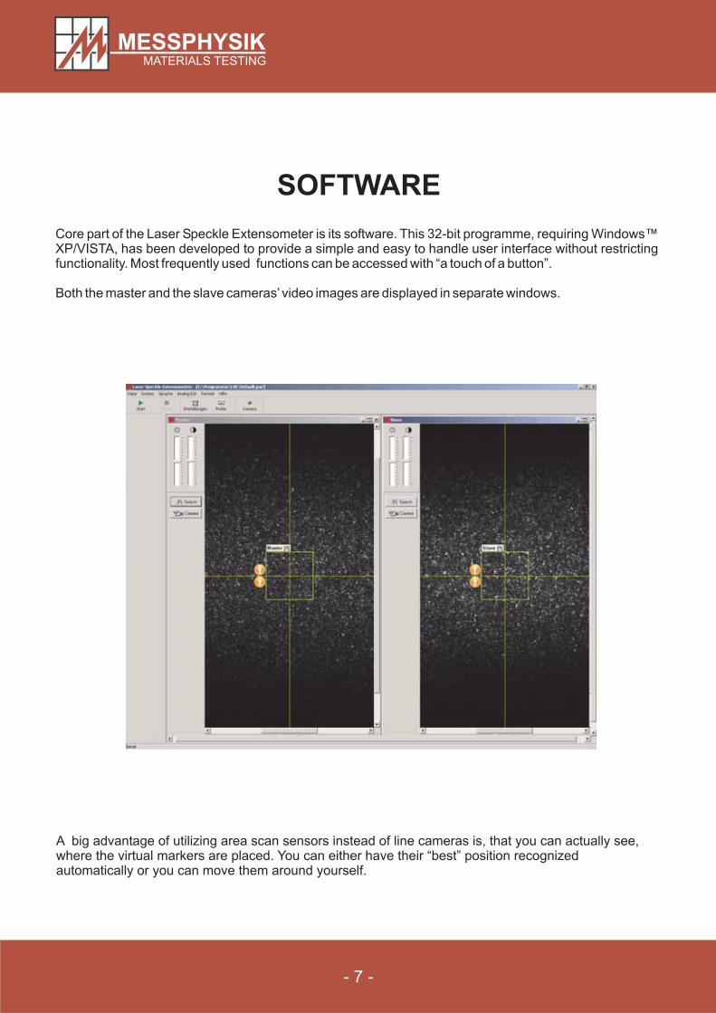
SOFTWARE
Core part of the Laser Speckle Extensometer is its software. This 32-bit programme, requiring Windows™XP/VISTA, has been developed to provide a simple and easy to handle user interface without restrictingfunctionality. Most frequently used functions can be accessed with “a touch of a button”.
Both the master and the slave cameras’video images are displayed in separate windows.
A big advantage of utilizing area scan sensors instead of line cameras is, that you can actually see,where the virtual markers are placed. You can either have their “best” position recognizedautomatically or you can move them around yourself.
SYSTEM INTEGRATION
- 8 -
In many cases the Laser Speckle Extensometer will be integral part of an entirely new MessphysikMaterials Testing system. But the capability to integrate it into virtually any existing third party system,enables you to work with this exciting new technology without having to purchase a new loading frame orcontroller.
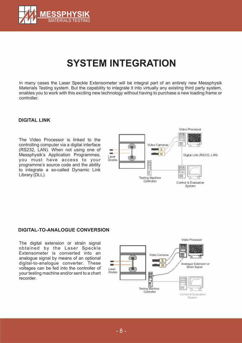
The Video Processor is linked to thecontrolling computer via a digital interface(RS232, LAN). When not using one ofMessphysik’s Application Programmes,you must have access to yourprogramme’s source code and the abilityto integrate a so-called Dynamic LinkLibrary (DLL).
DIGITAL LINK
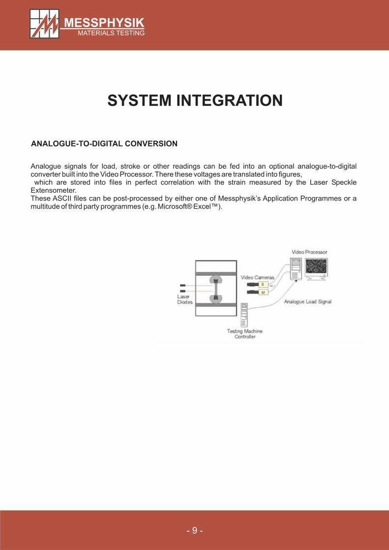
DIGITAL-TO-ANALOGUE CONVERSION
The digital extension or strain signalobta ined by the Laser SpeckleExtensometer is converted into ananalogue signal by means of an optionaldigital-to-analogue converter. Thesevoltages can be fed into the controller ofyour testing machine and/or sent to a chartrecorder.
- 9 -
SYSTEM INTEGRATION
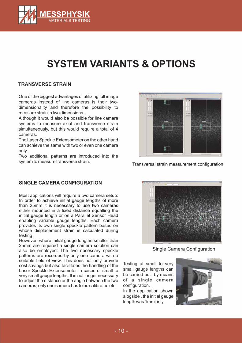
ANALOGUE-TO-DIGITAL CONVERSION
Analogue signals for load, stroke or other readings can be fed into an optional analogue-to-digitalconverter built into the Video Processor. There these voltages are translated into figures,which are stored into files in perfect correlation with the strain measured by the Laser Speckle
Extensometer.These ASCII files can be post-processed by either one of Messphysik’s Application Programmes or amultitude of third party programmes (e.g. Microsoft® Excel™).
- 10 -
SYSTEM VARIANTS & OPTIONS
Transversal strain measurement configuration
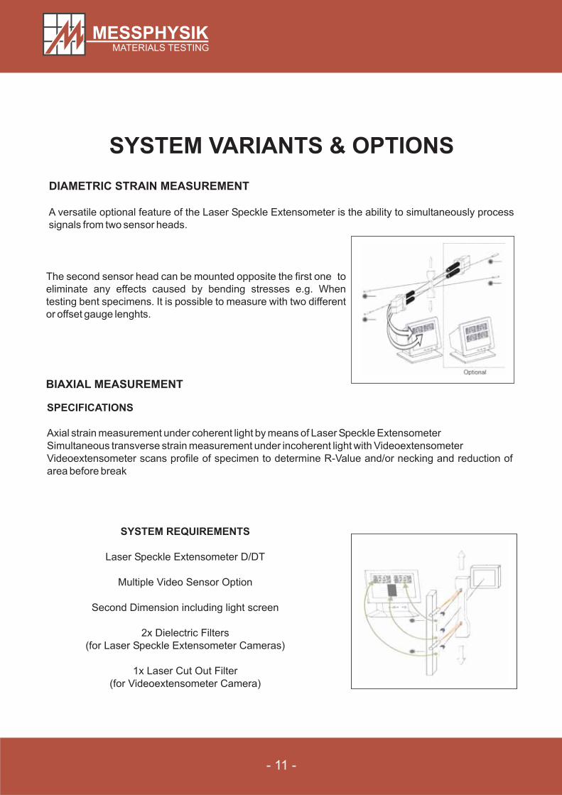
TRANSVERSE STRAIN
One of the biggest advantages of utilizing full image
cameras instead of line cameras is their two-
dimensionality and therefore the possibility to
measure strain in two dimensions.
Although it would also be possible for line camera
systems to measure axial and transverse strain
simultaneously, but this would require a total of 4
cameras.
The Laser Speckle Extensometer on the other hand
can achieve the same with two or even one camera
only.
Two additional patterns are introduced into the
system to measure transverse strain.
SINGLE CAMERA CONFIGURATION
Single Camera Configuration
Most applications will require a two camera setup:In order to achieve initial gauge lengths of morethan 25mm it is necessary to use two cameraseither mounted in a fixed distance equalling theinitial gauge length or on a Parallel Sensor Headenabling variable gauge lengths. Each cameraprovides its own single speckle pattern based onwhose displacement strain is calculated duringtesting.However, where initial gauge lengths smaller than25mm are required a single camera solution canalso be employed: The two necessary specklepatterns are recorded by only one camera with asuitable field of view. This does not only providecost savings but also facilitates the handling of theLaser Speckle Extensometer in cases of small tovery small gauge lengths: It is not longer necessaryto adjust the distance or the angle between the twocameras, only one camera has to be calibrated etc.
Testing at small to very
small gauge lengths can
be carried out by means
of a single camera
configuration.
In the application shown
alogside , the initial gauge
length was 1mm only.
- 11 -
SYSTEM VARIANTS & OPTIONS
DIAMETRIC STRAIN MEASUREMENT
A versatile optional feature of the Laser Speckle Extensometer is the ability to simultaneously process
signals from two sensor heads.
The second sensor head can be mounted opposite the first one to
eliminate any effects caused by bending stresses e.g. When
testing bent specimens. It is possible to measure with two different
or offset gauge lenghts.
BIAXIAL MEASUREMENT
SYSTEM REQUIREMENTS
Laser Speckle Extensometer D/DT
Multiple Video Sensor Option
Second Dimension including light screen
2x Dielectric Filters
(for Laser Speckle Extensometer Cameras)
1x Laser Cut Out Filter
(for Videoextensometer Camera)
SPECIFICATIONS
Axial strain measurement under coherent light by means of Laser Speckle Extensometer
Simultaneous transverse strain measurement under incoherent light with Videoextensometer
Videoextensometer scans profile of specimen to determine R-Value and/or necking and reduction of
area before break
- 12 -
APPLICATIONS
Because of the non-contacting nature of the Laser Speckle Extensometer and due to the fact that it makesmarkings unnecessary, this new type of extensometer allows direct strain measurement on materials or inenvironments never possible before.
Measuring E-Moduli of delicate materials such as thin films or metal foils do no longer pose problems norwill elevated or high temperatures - the Laser Speckle Extensometer is the ultimate solution.
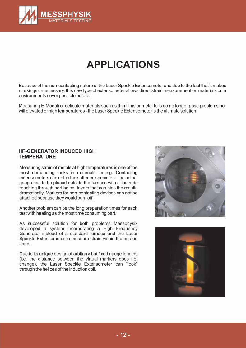
HF-GENERATOR INDUCED HIGHTEMPERATURE
Measuring strain of metals at high temperatures is one of themost demanding tasks in materials testing. Contactingextensometers can notch the softened specimen. The actualgauge has to be placed outside the furnace with silica rodsreaching through port holes levers that can bias the resultsdramatically. Markers for non-contacting devices can not beattached because they would burn off.
Another problem can be the long preparation times for eachtest with heating as the most time consuming part.
As successful solution for both problems Messphysikdeveloped a system incorporating a High FrequencyGenerator instead of a standard furnace and the LaserSpeckle Extensometer to measure strain within the heatedzone.
Due to its unique design of arbitrary but fixed gauge lengths(i.e. the distance between the virtual markers does notchange), the Laser Speckle Extensometer can “look”through the helices of the induction coil.
- 13 -
APPLICATIONS
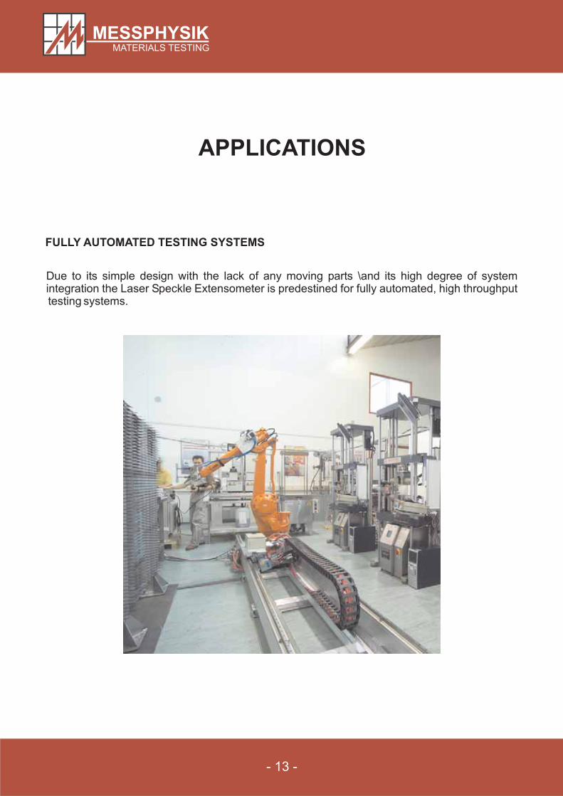
FULLY AUTOMATED TESTING SYSTEMS
Due to its simple design with the lack of any moving parts \and its high degree of systemintegration the Laser Speckle Extensometer is predestined for fully automated, high throughputtesting systems.
- 14 -
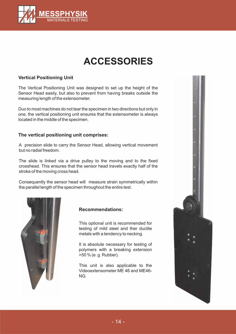
Vertical Positioning Unit
ACCESSORIES
The Vertical Positioning Unit was designed to set up the height of the
Sensor Head easily, but also to prevent from having breaks outside the
measuring length of the extensometer.
Duo to most machines do not tear the specimen in two directions but only in
one, the vertical positioning unit ensures that the extensometer is always
located in the middle of the specimen.
The vertical positioning unit comprises:
A precision slide to carry the Sensor Head, allowing vertical movement
but no radial freedom.
The slide is linked via a drive pulley to the moving and to the fixed
crosshead. This ensures that the sensor head travels exactly half of the
stroke of the moving cross head.
Consequently the sensor head will measure strain symmetrically within
the parallel length of the specimen throughout the entire test.
Recommendations:
This optional unit is recommended for
testing of mild steel and ther ductile
metals with a tendency to necking.
It is absolute necessary for testing of
polymers with a breaking extension
>50 % (e. g. Rubber).
This unit is also applicable to the
Videoextensometer ME 46 and ME46-
NG.
- 15 -
SPECIFICATIONS
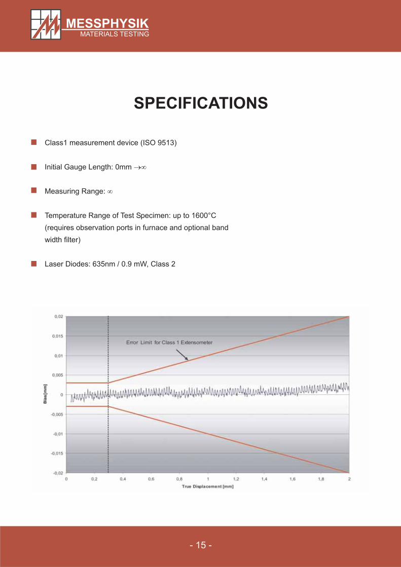
Class1 measurement device (ISO 9513)
Initial Gauge Length: 0mm
Measuring Range:
Temperature Range of Test Specimen: up to 1600°C
(requires observation ports in furnace and optional band
width filter)
Laser Diodes: 635nm / 0.9 mW, Class 2
�
�
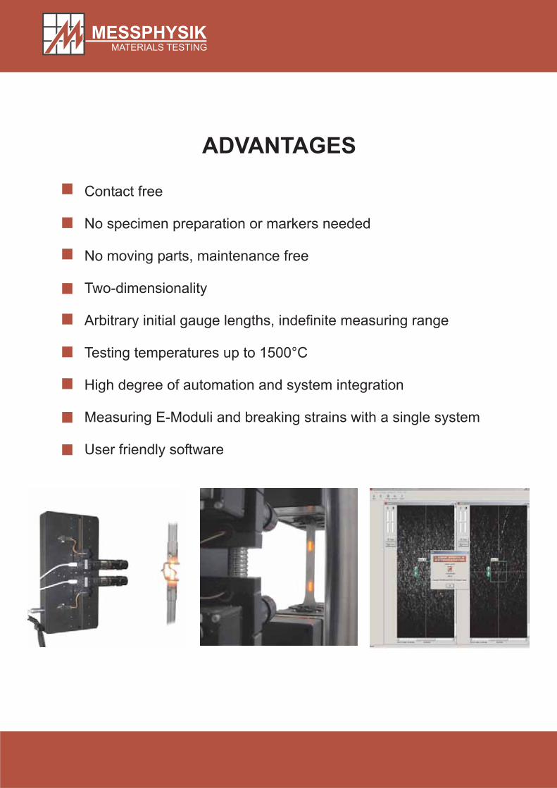
ADVANTAGES
Contact free
No specimen preparation or markers needed
No moving parts, maintenance free
Two-dimensionality
Arbitrary initial gauge lengths, indefinite measuring range
Testing temperatures up to 1500°C
High degree of automation and system integration
Measuring E-Moduli and breaking strains with a single system
User friendly software