Xerox 4635 Laser Printing System PC User Interface Reference
JlMN-Journal of Laser Micro/Nanoengineering Vol.1, No.2, 2006
Laser Precision Micro Fabrication in the Printing Industry Guido HENNIG, Karl Heinz SELBMANN, Stefan MATTHEUS, Ralph KECKE, Stephan BRÜNING*
MDC Max Daetwyler AG , Flugplatz, CH - 3368 Bleienbach, Switzerland *MDC Schepers, Karl Benzstrasse. 7, Vreden, Germany
e-mail: g.hennig @daetwyler-graphics.ch
The printing industry is a growing market for laser applications with a wide spectrum of different kinds of lasers having been established. This paper focuses on the precise micro structuring of gravure, flexo, and embossing print forms by direct laser ablation. The principle of gravure printing is the direct ink transfer from an ink source to the print substrate by small 3-dimensional cells engraved into the surface of a cylinder. Direct laser engraving into metallic cylinders is performed with a high power Q-switched Nd:YAG laser system tuned for high reproducibility and stability of the mean pulse energy (σ2< 1%). An exact modulation technique allows fast variation and precise calibration of the energy of each single laser pulse as well as active modulation of the intensity profile of the beam. This method permits to set diameter and depth of each cell independently from pulse to pulse at a rate of 70 kHz. The aspect ratio and the shape of each single cell can therefore be defined freely for each laser pulse controlled by digital image data. Thus the cell shape can be optimized for the best ink transfer characteristic on different print substrates.
e e
Keywords: Gravure Printing, Ablation, High Power Q-switched Nd:YAG Laser, Reproducibility Beam Profile Modulation, Ink Transfer Characteristic
1. Printing Technologies The traditional ways of print form fabrication using
analog copying methods based on films have been replaced effectively by modern digital imaging processes. Computer to Plate (CTP) or even directly Computer to Press are keywords for these new technologies, with improvements in quality and efficiency of many prepress and printing workflows. In this environment the application of lasers for print form fabrication plays an increasingly important role because of the high spatial resolution, the ability of fine focusing, the achievable high energy densities and the digital modulation.
The printing market is dominated by three main technologies: Gravure, Flexography and Offset Printing. The domains of Gravure are for the publication and packaging markets using all kinds of substrate materials like paper, plastics, or aluminum foil. The commonly used metallic print cylinder permits the highest numbers of runs in the press (Table 1, [1]). Flexography serves mainly the packaging market for all kind of consumables. The print form is made of hardened polymer or rubber and the maximum achievable number of runs is much lower than in Gravure. Daily newspapers are printed with offset because
of the low costs for the print form and high print runs. Other technologies like screen printing or new plateless methods, i.e. inkjet processes, or direct form writing inside the press cover the rest of the market. In the future especially the Direct Digital Printing (plateless technologies) will claim increased market share most likely at the expense of offset. Both serve the same market segments for low numbers of runs in the press, for example the ”print on demand jobs”. Specific and different print forms characterize each of the printing technologies.
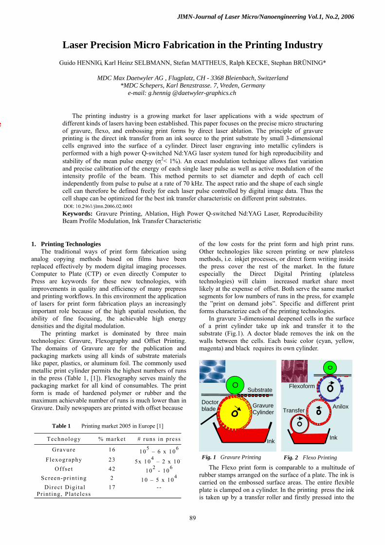
In gravure 3-dimensional deepened cells in the surface of a print cylinder take up ink and transfer it to the substrate (Fig.1). A doctor blade removes the ink on the walls between the cells. Each basic color (cyan, yellow, magenta) and black requires its own cylinder.
The Flexo print form is comparable to a multitude of
rubber stamps arranged on the surface of a plate. The ink is carried on the embossed surface areas. The entire flexible plate is clamped on a cylinder. In the printing press the ink is taken up by a transfer roller and firstly pressed into the
Table 1 Printing market 2005 in Europe [1]
Technology % marke t # runs in press
Gravure 16 105 – 6 x 10⁶
Flexography 23 5x 10⁴ – 2 x 10⁵
Offse t 42 102 - 106
Screen-pr in t ing 2 10 – 5 x 10⁴
Di rec t Digi ta l Pr in t ing , Pla te less
17 - -
Fig. 1 Gravure Printing Fig. 2 Flexo Printing
Gravure Cylinder
Ink
Doctor blade
Anilox
Flexoform
Ink
Substrate
Transfer
89
JlMN-Journal of Laser Micro/Nanoengineering Vol.1, No.2, 2006
uniform gravure cells of an Anilox cylinder, a ceramic gravure roller with a homogeneous cell screen for equal ink or glue transfer. The Anilox transfers the ink evenly to the raised surface parts of the flexo form which prints directly on the substrate (Fig.2).
In screen-printing textile webs and metallic stencils are used. The ink is pressed through a web or a pattern of tiny holes which particularly in case of metallic stencils can be drilled by laser.
In contrast to those 3-dimensional structured forms in Gravure and Screen Printing the Offset plate has a flat 2-dimensional surface with binary properties: Ink repelling areas and ink adhesive dots lay in the same plane (< 1 μm difference of levels). Greyscale values are achieved through different amounts of ink per pixel of an image as a result of different diameters of the individual ink dots (different area coverage). The process is therefore defined as area variable or autotypical.
2. Lasers in Print Form Manufacturing
The traditional imaging processes of the Offset plate, Flexoprint and Anilox roller as well as the Gravure cylinder have recently been replaced by laser micro structuring.
2.1 Imaging of Offset Plates The goal is to generate the ink repelling and ink
adhesive areas of an offset plate. Starting point is an aluminum base plate coated with a photopolymer and covered with a protection layer against scratches (Fig.3). The Polymer is modified locally by exposing with a scanning laser beam controlled with the data of a digital image. At the following chemical development the hardened polymer areas remain as a thin layer on the base plate repelling water, but binding silicon.
Further processing with hydration and silicon coating
enhances the hydrophilic and hydrophobic properties of the surface. The thickness of the silicon/photopolymer areas is less than 1 μm. For very high numbers of runs the photopolymer can „burned into“ the aluminium plate before chemical development. This enables up to 1 Million revolutions in the press, whereas without heat treatment the maximum runs are about 3x10⁵.
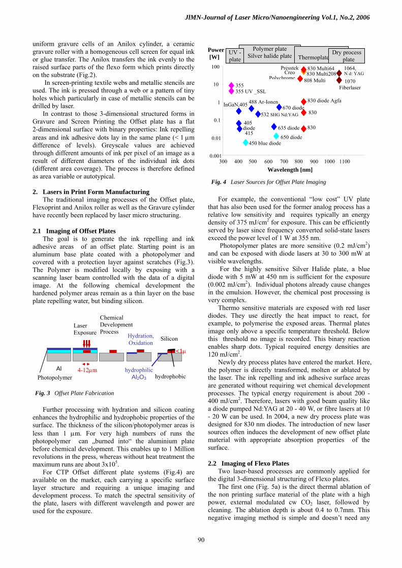
For CTP Offset different plate systems (Fig.4) are available on the market, each carrying a specific surface layer structure and requiring a unique imaging and development process. To match the spectral sensitivity of the plate, lasers with different wavelength and power are used for the exposure.
For example, the conventional “low cost” UV plate
that has also been used for the former analog process has a relative low sensitivity and requires typically an energy density of 375 mJ/cm2 for exposure. This can be efficiently served by laser since frequency converted solid-state lasers exceed the power level of 1 W at 355 nm.
Photopolymer plates are more sensitive (0.2 mJ/cm2) and can be exposed with diode lasers at 30 to 300 mW at visible wavelengths.
For the highly sensitive Silver Halide plate, a blue diode with 5 mW at 450 nm is sufficient for the exposure (0.002 mJ/cm2). Individual photons already cause changes in the emulsion. However, the chemical post processing is very complex.
Thermo sensitive materials are exposed with red laser diodes. They use directly the heat impact to react, for example, to polymerise the exposed areas. Thermal plates image only above a specific temperature threshold. Below this threshold no image is recorded. This binary reaction enables sharp dots. Typical required energy densities are 120 mJ/cm2.
Newly dry process plates have entered the market. Here, the polymer is directly transformed, molten or ablated by the laser. The ink repelling and ink adhesive surface areas are generated without requiring wet chemical development processes. The typical energy requirement is about 200 - 400 mJ/cm2. Therefore, lasers with good beam quality like a diode pumped Nd:YAG at 20 - 40 W, or fibre lasers at 10 - 20 W can be used. In 2004, a new dry process plate was designed for 830 nm diodes. The introduction of new laser sources often induces the development of new offset plate material with appropriate absorption properties of the surface.
830
830
830 Multi208
355 355 UV _SSL
405 diode 415
450 blue diode
488 Ar-Ionen
532 SHG Nd:YAG
InGaN,405 830 diode Agfa
808 Multi
670 diode
635 diode
650 diode
0.001
0.01
0.1
1
10
100
400 500 600 700 800 900 1000 1100Wavelength [nm]
Power [W
2.2 Imaging of Flexo Plates Two laser-based processes are commonly applied for
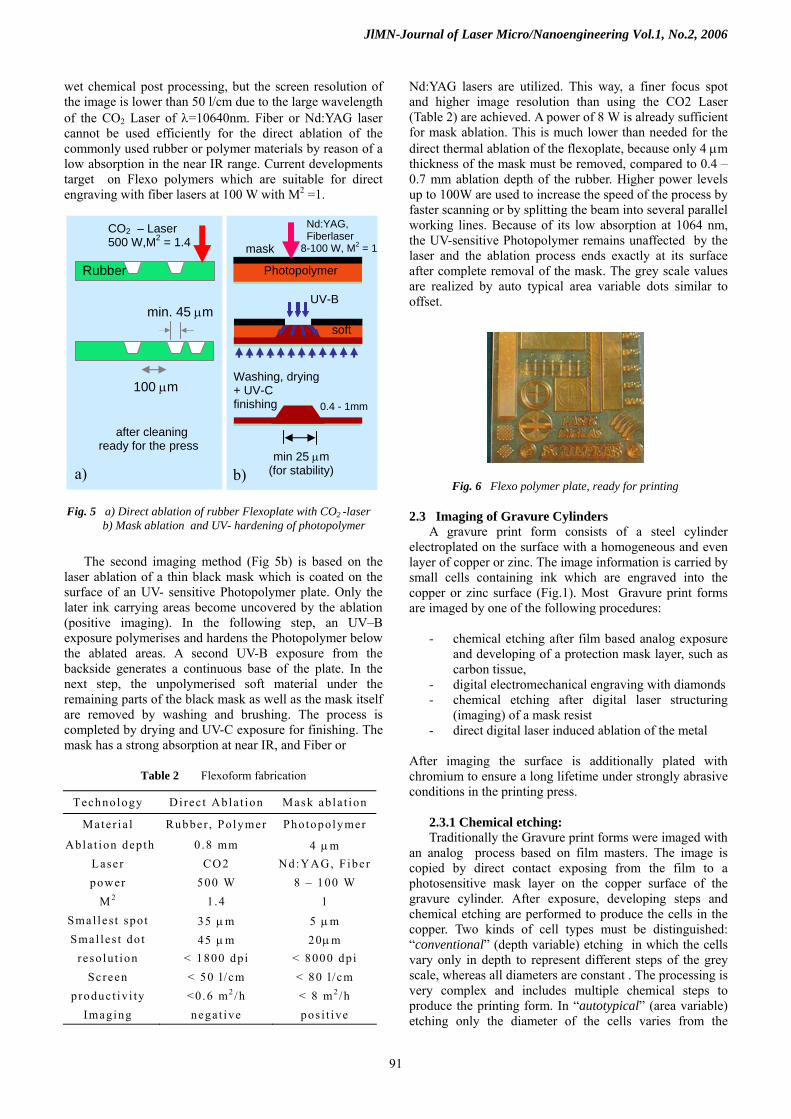
the digital 3-dimensional structuring of Flexo plates. The first one (Fig. 5a) is the direct thermal ablation of
the non printing surface material of the plate with a high power, external modulated cw CO2 laser, followed by cleaning. The ablation depth is about 0.4 to 0.7mm. This negative imaging method is simple and doesn’t need any
Fig. 3 Offset Plate Fabrication
Photopolymer
Chemical Development Process
Hydration, Oxidation
Silicon
<1μ
hydrophilic Al2O3 hydrophobic
4-12μm
Laser Exposure
Al
Fig. 4 Laser Sources for Offset Plate Imaging
300
]
Creo Polychrome
830 Multi64 Presstek
Polymer plate Silver halide plate
Thermoplate
UV - plate
Dry process plate
1070 Fiberlaser
1064, N d: YAG
90
JlMN-Journal of Laser Micro/Nanoengineering Vol.1, No.2, 2006
wet chemical post processing, but the screen resolution of the image is lower than 50 l/cm due to the large wavelength of the CO2 Laser of λ=10640nm. Fiber or Nd:YAG laser cannot be used efficiently for the direct ablation of the commonly used rubber or polymer materials by reason of a low absorption in the near IR range. Current developments target on Flexo polymers which are suitable for direct engraving with fiber lasers at 100 W with M2 =1.
The second imaging method (Fig 5b) is based on the
laser ablation of a thin black mask which is coated on the surface of an UV- sensitive Photopolymer plate. Only the later ink carrying areas become uncovered by the ablation (positive imaging). In the following step, an UV–B exposure polymerises and hardens the Photopolymer below the ablated areas. A second UV-B exposure from the backside generates a continuous base of the plate. In the next step, the unpolymerised soft material under the remaining parts of the black mask as well as the mask itself are removed by washing and brushing. The process is completed by drying and UV-C exposure for finishing. The mask has a strong absorption at near IR, and Fiber or
Nd:YAG lasers are utilized. This way, a finer focus spot and higher image resolution than using the CO2 Laser (Table 2) are achieved. A power of 8 W is already sufficient for mask ablation. This is much lower than needed for the direct thermal ablation of the flexoplate, because only 4 μm thickness of the mask must be removed, compared to 0.4 – 0.7 mm ablation depth of the rubber. Higher power levels up to 100W are used to increase the speed of the process by faster scanning or by splitting the beam into several parallel working lines. Because of its low absorption at 1064 nm, the UV-sensitive Photopolymer remains unaffected by the laser and the ablation process ends exactly at its surface after complete removal of the mask. The grey scale values are realized by auto typical area variable dots similar to offset.
CO2 – Laser 500 W,M2 = 1.4
Rubber
100 μm
min. 45 μm
after cleaning ready for the press
a)
Photopolymer
UV-B
soft
Washing, drying + UV-C finishing
mask
0.4 - 1mm
min 25 μm (for stability)b)
Nd:YAG, Fiberlaser 8-100 W, M2 = 1
Fig. 6 Flexo polymer plate, ready for printing
Fig. 5 a) Direct ablation of rubber Flexoplate with CO2 -laser 2.3 Imaging of Gravure Cylinders A gravure print form consists of a steel cylinder
electroplated on the surface with a homogeneous and even layer of copper or zinc. The image information is carried by small cells containing ink which are engraved into the copper or zinc surface (Fig.1). Most Gravure print forms are imaged by one of the following procedures:
b) Mask ablation and UV- hardening of photopolymer
- chemical etching after film based analog exposure and developing of a protection mask layer, such as carbon tissue,
- digital electromechanical engraving with diamonds - chemical etching after digital laser structuring
(imaging) of a mask resist - direct digital laser induced ablation of the metal
After imaging the surface is additionally plated with chromium to ensure a long lifetime under strongly abrasive conditions in the printing press.
Table 2 Flexoform fabrication
Technology Di rec t Abla t ion Mask abla t ion 2.3.1 Chemical etching: Mater ia l Rubber , Polymer PhotopolymerTraditionally the Gravure print forms were imaged with
an analog process based on film masters. The image is copied by direct contact exposing from the film to a photosensitive mask layer on the copper surface of the gravure cylinder. After exposure, developing steps and chemical etching are performed to produce the cells in the copper. Two kinds of cell types must be distinguished: “conventional” (depth variable) etching in which the cells vary only in depth to represent different steps of the grey scale, whereas all diameters are constant . The processing is very complex and includes multiple chemical steps to produce the printing form. In “autotypical” (area variable) etching only the diameter of the cells varies from the
Abla t ion dep th 0 .8 mm 4 μm Laser CO2 Nd:YAG, F iberpower 500 W 8 – 100 W
M 2 1 .4 1 Smal les t spo t 35 μm 5 μm Smal les t do t 45 μm 20μm
resolut ion < 1800 dpi < 8000 dpi Sc reen < 50 l /cm < 80 l /cm
produc t iv i ty <0.6 m2 /h < 8 m 2 /h Imaging negat ive pos i t ive
91
JlMN-Journal of Laser Micro/Nanoengineering Vol.1, No.2, 2006
highlights to the shadows of the greyscale and all cells are equal in depth. This processing is easy to control by the exposed areas of the mask and by the time of etching. These definitions are also valid to distinguish different types of laser engraved cells.
2.3.2 Electromechanical Gravure: The electromechanical engraving method allows the
realisation of digital imaging in Gravure. An oscillating diamond stylus cuts the cells directly into the Copper or zinc surface of the slowly revolving Gravure cylinder. The diamond draws a helical or circular line of cells as the engraving head moves continuously or by stepping along the axis of the cylinder. At common screens each oscillation generates one cell. The volume of the cell depends on the amplitude of the diamonds oscillation and is controlled by digital image data. The maximum frequency of the oscillation is about 8-10 kHz restricted by mechanical resonance of the diamonds holder and thermal heat dissipation capacities of the electromagnetic drive.
According to the tonal values, the diamond stylus cuts into the Cu surface producing cells with variable diameter and variable depth, but always with the fixed aspect ratio defined by the diamonds geometry (Fig. 7). This is described as “halfautotypical cell type”.
2.3.3 Digital laser structuring of a mask resist The mask ablation for Gravure is similar to the one
used for the flexo form. Therefore, flexo and gravure forms can be micro-structured with the same laser source and the same machine (for example, the Digilas of MDC – Schepers). Even the lacquer for the mask can be the same. However, the base material of the form is copper and the pre- and post-processing steps are different. The complete workflow cycle for the gravure cylinder processing with the mask ablation / etching method is shown in Fig. 8. When the cylinder comes back from the printing press, the previous image has to be removed by chemical deplating of the chromium and the imaged upper layer of the copper. The next step is the new electroplating with copper and a mechanical polishing of the surface. The black mask is applied by immersion or spray coating. The laser imaging removes the mask by thermal ablation at the areas that later will print (positive imaging, Fig. 9). The copper is not
Deplating of used Cr, Cu
Cu Plating, Finishing Mask Coating Laser processing
Etching
Cleaning Cr - Plating Printing Fig.8 Gravure, Complete Workflow Mask Resist Ablation
affected by the laser process because the ablation threshold for Cu is much higher than for the mask. Time controlled chemical etching generates about 10 to 50 μm deep gravure cells in the copper surface. The cells are autotypical, having all the same depth, but different diameter for different grey steps. After cleaning the cylinder is electroplated with a 5 μm thick chromium layer to guarantee a long stability of the form in the press.
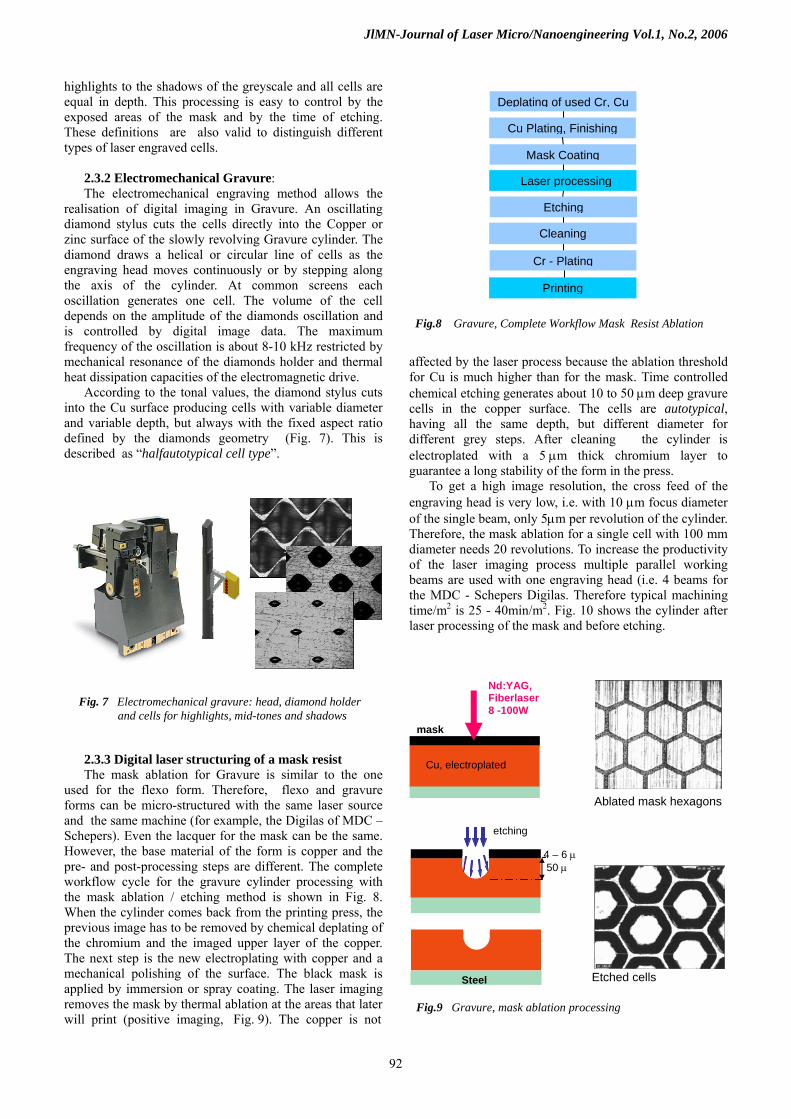
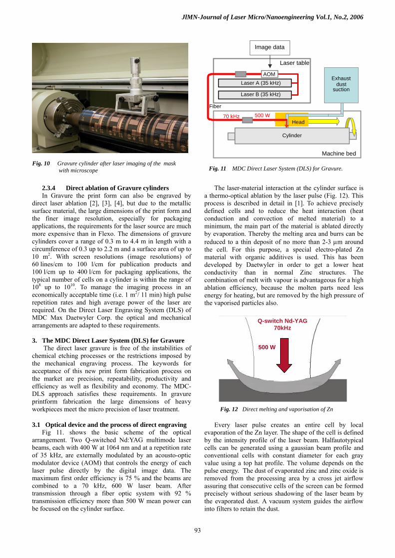
To get a high image resolution, the cross feed of the engraving head is very low, i.e. with 10 μm focus diameter of the single beam, only 5μm per revolution of the cylinder. Therefore, the mask ablation for a single cell with 100 mm diameter needs 20 revolutions. To increase the productivity of the laser imaging process multiple parallel working beams are used with one engraving head (i.e. 4 beams for the MDC - Schepers Digilas. Therefore typical machining time/m2 is 25 - 40min/m2. Fig. 10 shows the cylinder after laser processing of the mask and before etching.
Fig. 7 Electromechanical gravure: head, diamond holder and cells for highlights, mid-tones and shadows
etching
Steel
Cu, electroplated
Nd:YAG, Fiberlaser 8 -100W
mask
4 – 6 μ 50 μ
Ablated mask hexagons
Etched cells
Fig.9 Gravure, mask ablation processing
92
JlMN-Journal of Laser Micro/Nanoengineering Vol.1, No.2, 2006
2.3.4 Direct ablation of Gravure cylinders In Gravure the print form can also be engraved by
direct laser ablation [2], [3], [4], but due to the metallic surface material, the large dimensions of the print form and the finer image resolution, especially for packaging applications, the requirements for the laser source are much more expensive than in Flexo. The dimensions of gravure cylinders cover a range of 0.3 m to 4.4 m in length with a circumference of 0.3 up to 2.2 m and a surface area of up to 10 m2. With screen resolutions (image resolutions) of 60 lines/cm to 100 l/cm for publication products and 100 l/cm up to 400 l/cm for packaging applications, the typical number of cells on a cylinder is within the range of 108 up to 1010. To manage the imaging process in an economically acceptable time (i.e. 1 m2/ 11 min) high pulse repetition rates and high average power of the laser are required. On the Direct Laser Engraving System (DLS) of MDC Max Daetwyler Corp. the optical and mechanical arrangements are adapted to these requirements.
3. The MDC Direct Laser System (DLS) for Gravure
The direct laser gravure is free of the instabilities of chemical etching processes or the restrictions imposed by the mechanical engraving process. The keywords for acceptance of this new print form fabrication process on the market are precision, repeatability, productivity and efficiency as well as flexibility and economy. The MDC-DLS approach satisfies these requirements. In gravure printform fabrication the large dimensions of heavy workpieces meet the micro precision of laser treatment.
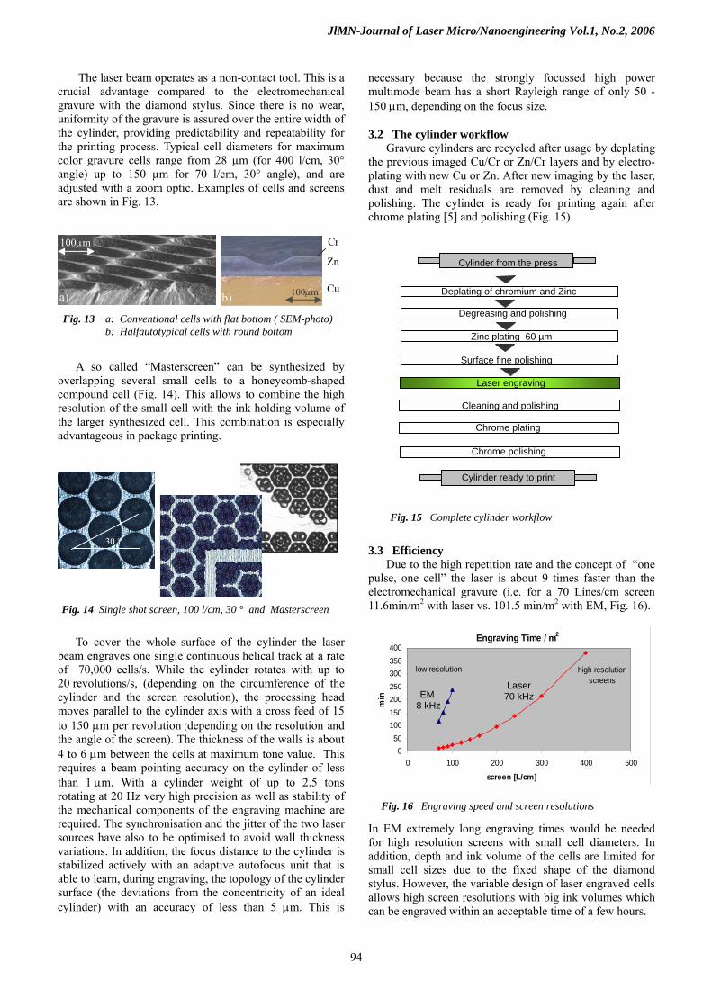
3.1 Optical device and the process of direct engraving Fig 11. shows the basic scheme of the optical
arrangement. Two Q-switched Nd:YAG multimode laser beams, each with 400 W at 1064 nm and at a repetition rate of 35 kHz, are externally modulated by an acousto-optic modulator device (AOM) that controls the energy of each laser pulse directly by the digital image data. The maximum first order efficiency is 75 % and the beams are combined to a 70 kHz, 600 W laser beam. After transmission through a fiber optic system with 92 % transmission efficiency more than 500 W mean power can be focused on the cylinder surface.
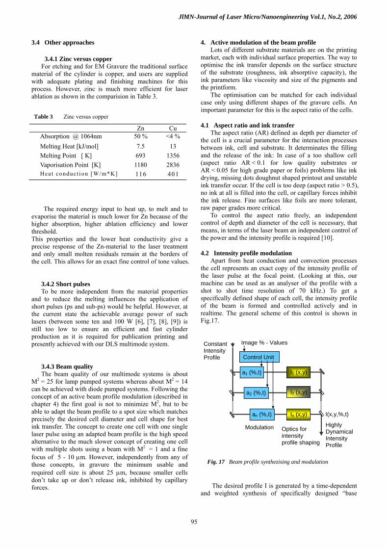
The laser-material interaction at the cylinder surface is
a thermo-optical ablation by the laser pulse (Fig. 12). This process is described in detail in [1]. To achieve precisely defined cells and to reduce the heat interaction (heat conduction and convection of melted material) to a minimum, the main part of the material is ablated directly by evaporation. Thereby the melting area and burrs can be reduced to a thin deposit of no more than 2-3 μm around the cell. For this purpose, a special electro-plated Zn material with organic additives is used. This has been developed by Daetwyler in order to get a lower heat conductivity than in normal Zinc structures. The combination of melt with vapour is advantageous for a high ablation efficiency, because the molten parts need less energy for heating, but are removed by the high pressure of the vaporised particles also.
Every laser pulse creates an entire cell by local
evaporation of the Zn layer. The shape of the cell is defined by the intensity profile of the laser beam. Halfautotypical cells can be generated using a gaussian beam profile and conventional cells with constant diameter for each gray value using a top hat profile. The volume depends on the pulse energy. The dust of evaporated zinc and zinc oxide is removed from the processing area by a cross jet airflow assuring that consecutive cells of the screen can be formed precisely without serious shadowing of the laser beam by the evaporated dust. A vacuum system guides the airflow into filters to retain the dust.
Fig. 10 Gravure cylinder after laser imaging of the mask with microscope Fig. 11 MDC Direct Laser System (DLS) for Gravure.
Fiber
Laser A (35 kHz)
Laser B (35 kHz)
Exhaust dust
suction
70 kHz
AOM
Head
Cylinder
Machine bed
Laser table
Image data
500 W
Q-switch Nd-YAG 70kHz
500 W
Fig. 12 Direct melting and vaporisation of Zn
93
JlMN-Journal of Laser Micro/Nanoengineering Vol.1, No.2, 2006
The laser beam operates as a non-contact tool. This is a crucial advantage compared to the electromechanical gravure with the diamond stylus. Since there is no wear, uniformity of the gravure is assured over the entire width of the cylinder, providing predictability and repeatability for the printing process. Typical cell diameters for maximum color gravure cells range from 28 µm (for 400 l/cm, 30° angle) up to 150 µm for 70 l/cm, 30° angle), and are adjusted with a zoom optic. Examples of cells and screens are shown in Fig. 13.
A so called “Masterscreen” can be synthesized by
overlapping several small cells to a honeycomb-shaped compound cell (Fig. 14). This allows to combine the high resolution of the small cell with the ink holding volume of the larger synthesized cell. This combination is especially advantageous in package printing.
To cover the whole surface of the cylinder the laser
beam engraves one single continuous helical track at a rate of 70,000 cells/s. While the cylinder rotates with up to 20 revolutions/s, (depending on the circumference of the cylinder and the screen resolution), the processing head moves parallel to the cylinder axis with a cross feed of 15 to 150 μm per revolution (depending on the resolution and the angle of the screen). The thickness of the walls is about 4 to 6 μm between the cells at maximum tone value. This requires a beam pointing accuracy on the cylinder of less than 1 μm. With a cylinder weight of up to 2.5 tons rotating at 20 Hz very high precision as well as stability of the mechanical components of the engraving machine are required. The synchronisation and the jitter of the two laser sources have also to be optimised to avoid wall thickness variations. In addition, the focus distance to the cylinder is stabilized actively with an adaptive autofocus unit that is able to learn, during engraving, the topology of the cylinder surface (the deviations from the concentricity of an ideal cylinder) with an accuracy of less than 5 μm. This is
necessary because the strongly focussed high power multimode beam has a short Rayleigh range of only 50 - 150 μm, depending on the focus size.
3.2 The cylinder workflow Gravure cylinders are recycled after usage by deplating
the previous imaged Cu/Cr or Zn/Cr layers and by electro-plating with new Cu or Zn. After new imaging by the laser, dust and melt residuals are removed by cleaning and polishing. The cylinder is ready for printing again after chrome plating [5] and polishing (Fig. 15).
Deplating of chromium and Zinc
Degreasing and polishing
Zinc plating 60 µm
Surface fine polishing
Laser engraving
Cleaning and polishing
Chrome plating
Chrome polishing
Cylinder from the press
Cylinder ready to print
100μm Cr
Zn
Cu100μma) b)
Fig. 13 a: Conventional cells with flat bottom ( SEM-photo) b: Halfautotypical cells with round bottom
Fig. 15 Complete cylinder workflow
30 ° 3.3 Efficiency
Due to the high repetition rate and the concept of “one pulse, one cell” the laser is about 9 times faster than the electromechanical gravure (i.e. for a 70 Lines/cm screen 11.6min/m2 with laser vs. 101.5 min/m2 with EM, Fig. 16). Fig. 14 Single shot screen, 100 l/cm, 30 ° and Masterscreen
Engraving Time / m2
050
In EM extremely long engraving times would be needed for high resolution screens with small cell diameters. In addition, depth and ink volume of the cells are limited for small cell sizes due to the fixed shape of the diamond stylus. However, the variable design of laser engraved cells allows high screen resolutions with big ink volumes which can be engraved within an acceptable time of a few hours.
Fig. 16 Engraving speed and screen resolutions
100150200250300350400
0 100 200 300 400 500
screen [L/cm]
min
high resolution screens
low resolution
EM 8 kHz
Laser 70 kHz
94
JlMN-Journal of Laser Micro/Nanoengineering Vol.1, No.2, 2006
3.4 Other approaches
3.4.1 Zinc versus copper For etching and for EM Gravure the traditional surface
material of the cylinder is copper, and users are supplied with adequate plating and finishing machines for this process. However, zinc is much more efficient for laser ablation as shown in the comparision in Table 3.
The required energy input to heat up, to melt and to evaporise the material is much lower for Zn because of the higher absorption, higher ablation efficiency and lower threshold. This properties and the lower heat conductivity give a precise response of the Zn-material to the laser treatment and only small molten residuals remain at the borders of the cell. This allows for an exact fine control of tone values.
3.4.2 Short pulses To be more independent from the material properties
and to reduce the melting influences the application of short pulses (ps and sub-ps) would be helpful. However, at the current state the achievable average power of such lasers (between some ten and 100 W [6], [7], [8], [9]) is still too low to ensure an efficient and fast cylinder production as it is required for publication printing and presently achieved with our DLS multimode system.
3.4.3 Beam quality The beam quality of our multimode systems is about
M2 = 25 for lamp pumped systems whereas about M2 = 14 can be achieved with diode pumped systems. Following the concept of an active beam profile modulation (described in chapter 4) the first goal is not to minimize M2, but to be able to adapt the beam profile to a spot size which matches precisely the desired cell diameter and cell shape for best ink transfer. The concept to create one cell with one single laser pulse using an adapted beam profile is the high speed alternative to the much slower concept of creating one cell with multiple shots using a beam with M2 = 1 and a fine focus of 5 - 10 μm. However, independently from any of those concepts, in gravure the minimum usable and required cell size is about 25 μm, because smaller cells don’t take up or don’t release ink, inhibited by capillary forces.
4. Active modulation of the beam profile Lots of different substrate materials are on the printing
market, each with individual surface properties. The way to optimise the ink transfer depends on the surface structure of the substrate (roughness, ink absorptive capacity), the ink parameters like viscosity and size of the pigments and the printform.
The optimisation can be matched for each individual case only using different shapes of the gravure cells. An important parameter for this is the aspect ratio of the cells.
Table 3 Zinc versus copper 4.1 Aspect ratio and ink transfer
The aspect ratio (AR) defined as depth per diameter of the cell is a crucial parameter for the interaction processes between ink, cell and substrate. It determinates the filling and the release of the ink: In case of a too shallow cell (aspect ratio AR < 0.1 for low quality substrates or AR < 0.05 for high grade paper or foils) problems like ink drying, missing dots doughnut shaped printout and unstable ink transfer occur. If the cell is too deep (aspect ratio > 0.5), no ink at all is filled into the cell, or capillary forces inhibit the ink release. Fine surfaces like foils are more tolerant, raw paper grades more critical.
To control the aspect ratio freely, an independent control of depth and diameter of the cell is necessary, that means, in terms of the laser beam an independent control of the power and the intensity profile is required [10].
Zn Cu Absorption @ 1064nm 50 % <4 % Melting Heat [kJ/mol] 7.5 13 Melting Point [ K] 693 1356 Vaporisation Point [K] 1180 2836
116 401 Hea t conduct ion [W/m*K]
4.2 Intensity profile modulation Apart from heat conduction and convection processes
the cell represents an exact copy of the intensity profile of the laser pulse at the focal point. (Looking at this, our machine can be used as an analyser of the profile with a shot to shot time resolution of 70 kHz.) To get a specifically defined shape of each cell, the intensity profile of the beam is formed and controlled actively and in realtime. The general scheme of this control is shown in Fig.17.
The desired profile I is generated by a time-dependent
and weighted synthesis of specifically designed “base
a1 (%,t)
In (x,y) an (%,t)
a2 (%,t) I2 (x,y)
I1 (x,y)
Control Unit
Constant Intensity Profile
Highly DynamicalIntensity Profile
Image % - Values
Modulation Optics for intensity profile shaping
I(x,y,%,t)
Fig. 17 Beam profile synthezising and modulation
95
JlMN-Journal of Laser Micro/Nanoengineering Vol.1, No.2, 2006
profiles“ In(x,y), each of which is prepared by its own optical arrangement:
I (x,y,%,t) = Σ an (%,t) In (x,y) (1)
(with t = time, % = grey value of an image pixel).
To prepare base profiles, various optical components
can be applied like apertures, spherical and cylindrical lenses, DOEs and phase plates. The time dependent coefficients an are controlled by the %- tone values of the image file. Like them they can be changed from pixel to pixel with the same frequency as the Q - switch pulses are generated (i.e. in our case with 70 kHz). For higher repetition rates faster changes are possible accordingly.
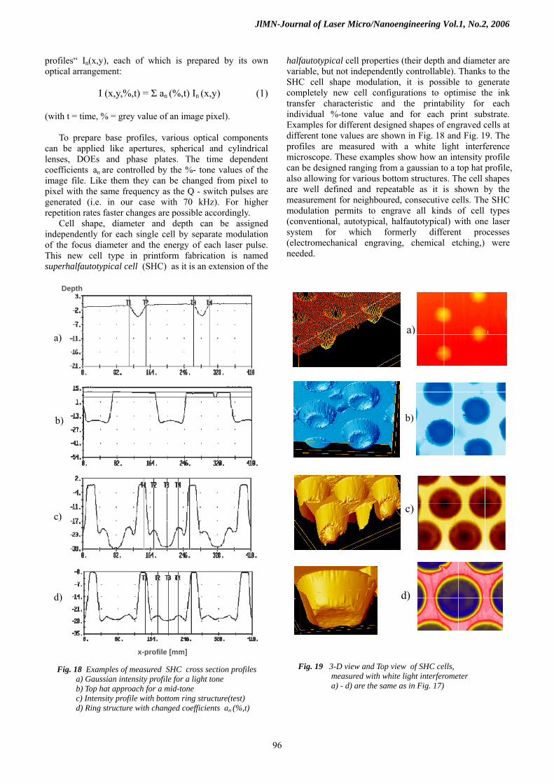
Cell shape, diameter and depth can be assigned independently for each single cell by separate modulation of the focus diameter and the energy of each laser pulse. This new cell type in printform fabrication is named superhalfautotypical cell (SHC) as it is an extension of the
halfautotypical cell properties (their depth and diameter are variable, but not independently controllable). Thanks to the SHC cell shape modulation, it is possible to generate completely new cell configurations to optimise the ink transfer characteristic and the printability for each individual %-tone value and for each print substrate. Examples for different designed shapes of engraved cells at different tone values are shown in Fig. 18 and Fig. 19. The profiles are measured with a white light interference microscope. These examples show how an intensity profile can be designed ranging from a gaussian to a top hat profile, also allowing for various bottom structures. The cell shapes are well defined and repeatable as it is shown by the measurement for neighboured, consecutive cells. The SHC modulation permits to engrave all kinds of cell types (conventional, autotypical, halfautotypical) with one laser system for which formerly different processes (electromechanical engraving, chemical etching,) were needed.
Depth
a)
Fig. 18 Examples of measured SHC cross section profiles a) Gaussian intensity profile for a light tone b) Top hat approach for a mid-tone c) Intensity profile with bottom ring structure(test) d) Ring structure with changed coefficients an (%,t)
a)
b) b)
c) c)
d) d)
x-profile [mm]
Fig. 19 3-D view and Top view of SHC cells, measured with white light interferometer a) - d) are the same as in Fig. 17)
96
JlMN-Journal of Laser Micro/Nanoengineering Vol.1, No.2, 2006
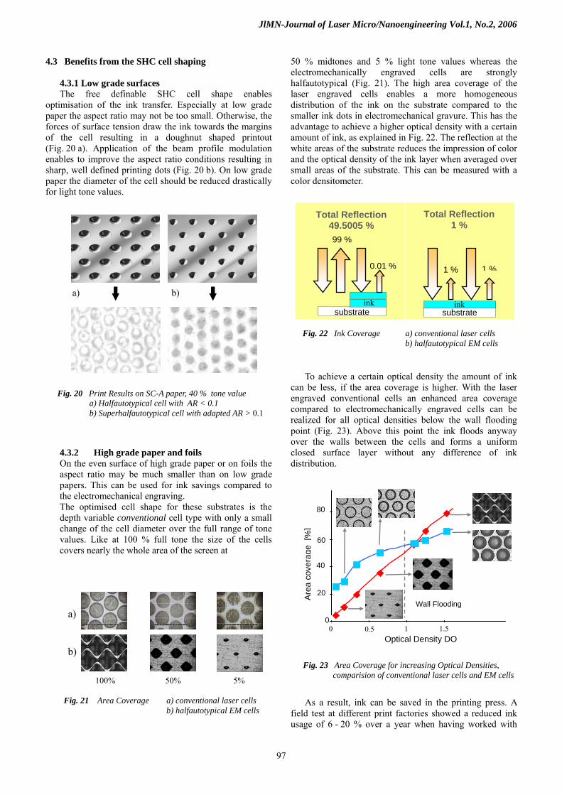
4.3 Benefits from the SHC cell shaping 4.3.1 Low grade surfaces The free definable SHC cell shape enables
optimisation of the ink transfer. Especially at low grade paper the aspect ratio may not be too small. Otherwise, the forces of surface tension draw the ink towards the margins of the cell resulting in a doughnut shaped printout (Fig. 20 a). Application of the beam profile modulation enables to improve the aspect ratio conditions resulting in sharp, well defined printing dots (Fig. 20 b). On low grade paper the diameter of the cell should be reduced drastically for light tone values.
4.3.2 High grade paper and foils On the even surface of high grade paper or on foils the aspect ratio may be much smaller than on low grade papers. This can be used for ink savings compared to the electromechanical engraving. The optimised cell shape for these substrates is the depth variable conventional cell type with only a small change of the cell diameter over the full range of tone values. Like at 100 % full tone the size of the cells covers nearly the whole area of the screen at
50 % midtones and 5 % light tone values whereas the electromechanically engraved cells are strongly halfautotypical (Fig. 21). The high area coverage of the laser engraved cells enables a more homogeneous distribution of the ink on the substrate compared to the smaller ink dots in electromechanical gravure. This has the advantage to achieve a higher optical density with a certain amount of ink, as explained in Fig. 22. The reflection at the white areas of the substrate reduces the impression of color and the optical density of the ink layer when averaged over small areas of the substrate. This can be measured with a color densitometer.
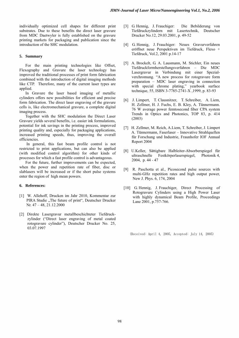
To achieve a certain optical density the amount of ink
can be less, if the area coverage is higher. With the laser engraved conventional cells an enhanced area coverage compared to electromechanically engraved cells can be realized for all optical densities below the wall flooding point (Fig. 23). Above this point the ink floods anyway over the walls between the cells and forms a uniform closed surface layer without any difference of ink distribution.
As a result, ink can be saved in the printing press. A
field test at different print factories showed a reduced ink usage of 6 - 20 % over a year when having worked with
a) b)
Fig. 20 Print Results on SC-A paper, 40 % tone value a) Halfautotypical cell with AR < 0.1 b) Superhalfautotypical cell with adapted AR > 0.1
Fig. 21 Area Coverage a) conventional laser cells b) halfautotypical EM cells
100% 50% 5%
a)
b)
a) b)
Wall Flooding
0
20
40
60
80
0 0.5 1 1.5 Optical Density DO
Are
a co
vera
ge [
%]
Fig. 23 Area Coverage for increasing Optical Densities, comparision of conventional laser cells and EM cells
Fig. 22 Ink Coverage a) conventional laser cells b) halfautotypical EM cells
0.01 %
substrate substrate
1 %1 %
ink ink
Total Reflection 49.5005 %
Total Reflection 1 %
99 %
97
JlMN-Journal of Laser Micro/Nanoengineering Vol.1, No.2, 2006
individually optimized cell shapes for different print substrates. Due to these benefits the direct laser gravure from MDC Daetwyler is fully established on the gravure printing markets for packaging and publication since the introduction of the SHC modulation. 5. Summary
For the main printing technologies like Offset,
Flexography and Gravure the laser technology has improved the traditional processes of print form fabrication combined with the introduction of digital imaging methods like CTP. Therefore, many of the current laser types are applied.
In Gravure the laser based imaging of metallic cylinders offers new possibilities for efficient and precise form fabrication. The direct laser engraving of the gravure cells is, like electromechanical gravure, a complete digital imaging process.
Together with the SHC modulation the Direct Laser Gravure yields several benefits, i.e. easier ink formulations, potential for ink savings in the printing process, improved printing quality and, especially for packaging applications, increased printing speeds, thus, improving the overall efficiencies.
In general, this fast beam profile control is not restricted to print applications, but can also be applied (with modified control algorithm) for other kinds of processes for which a fast profile control is advantageous.
For the future, further improvements can be expected, when the power and repetition rate of fiber, disc or slablasers will be increased or if the short pulse systems enter the region of high mean powers.
6. References: [1] W. Allehoff, Drucken im Jahr 2010, Kommentar zur PIRA Studie „The future of print“, Deutscher Drucker Nr. 47 – 48, 21.12.2000
[2] Direkte Lasergravur metallbeschichteter Tiefdruck- zylinder (“Direct laser engraving of metal coated rotogravure cylinder”), Deutscher Drucker No. 25, 03.07.1997
[3] G. Hennig, J. Frauchiger: Die Bebilderung von Tiefdruckzylindern mit Lasertechnik, Deutscher Drucker No.12, 29.03.2001, p. 49-52 [4] G. Hennig, J. Frauchiger: Neues Gravurverfahren eröffnet neue Perspektiven im Tiefdruck, Flexo + Tiefdruck, Vol.2, 2001 p.14-17 [5] A. Brockelt, G. A. Lausmann, M. Stichler, Ein neues Tiefdruckformherstellungsverfahren – Die MDC Lasergravur in Verbindung mit einer Spezial- verchromung. “A new process for rotogravure form preparation – MDC laser engraving in connection with special chrome plating,” yearbook surface technique, 55, ISBN 3-7785-2741-X ,1999, p. 83-93 [6] J. Limpert, T. Clausnitzer, T. Schreiber, A. Liem, H. Zellmer, H. J. Fuchs, E. B. Kley, A. Tünnermann. 76 W average power femtosecond fiber CPA system Trends in Optics and Photonics, TOP 83, p. 414 (2003) [7] H. Zellmer, M. Reich, A.Liem, T. Schreiber, J. Limpert A. Tünnermann, Faserlaser – Innovative Strahlquellen für Forschung und Industrie, Fraunhofer IOF Annual Report 2004
[8] U.Keller, Sättigbare Halbleiter-Absorberspiegel für ultraschnelle Festkörperlaserspiegel, Photonik 4, 2004, p. 44 - 47
[9] R. Paschotta et al., Picosecond pulse sources with multi-GHz repetition rates and high output power, New J. Phys. 6, 174, 2004
[10] G. Hennig, J. Frauchiger, Direct Processing of Rotogravure Cylinders using a High Power Laser with highly dynamical Beam Profile, Proceedings Lane 2001, p.757-766.
(Received: April 4, 2005, Accepted: July 14, 2005)
98