Laser Engraving & Cutting Control System - · PDF fileLaser Engraving & Cutting Control System...
69
Laser Laser Laser Laser Engraving Engraving Engraving Engraving & Cutting Cutting Cutting Cutting Control Control Control Control System System System System DSP5.3 DSP5.3 DSP5.3 DSP5.3 Manual Manual Manual Manual V1.6 V1.6 V1.6 V1.6 May, May, May, May, 2010 2010 2010 2010
Transcript of Laser Engraving & Cutting Control System - · PDF fileLaser Engraving & Cutting Control System...
LaserLaserLaserLaser EngravingEngravingEngravingEngraving &&&&CuttingCuttingCuttingCutting ControlControlControlControl SystemSystemSystemSystem
DSP5.3DSP5.3DSP5.3DSP5.3
ManualManualManualManual
V1.6V1.6V1.6V1.6
May,May,May,May, 2010201020102010
Laser Engraving & Cutting Control System Manual
2
ContentContentContentContent
Content 21 System Installation 41 System Installation 4
1.1 Contents of the Control System 41.2 Installation of the System 4
2 CorelDraw Output Edition 62.1 Laser Output 62.2 Import DST file 102.3 Output file 102.4 Laser Machine Setting 103.1 Laser Output 113.2 Output Data 113.3 Laser Machine Set 113.4 Unite Lines 11
4 Universal Edition 124.1 File 124.2 Edit 144.3 Drawing 164.4 Tool 204.5 Laser processing 244.6 View 284.7 Help 28
5 Laser Output 305.1 Layer Management 305.2 Testing 355.3 Auxiliary processing parameter 365.4 Procession File(Download Data) 37
6 Machine Setting 406.1 Machine Interface 406.2 Controller Card 416.3 Worktable 426.4 Feeding 446.5 Laser Cutting 456.6 Laser Engraving 476.7 Grade Engraving 486.8 Hole 486.9 Chalk Line 48
7 PAD06/PAD03 Control Panel 507.1 PAD06 Main Interface 507.2 PAD03 Main Interface 50
8 Text display Control Panel 54
Laser Engraving & Cutting Control System Manual
3
8.1 Main Interface 548.2 Jog Set Interface 558.3 Laser Set Interface 558.4 Processing Interface 55
9 Error Alarm Interface 579.1 Error Alarm Interface 579.2 Soft Limit Stop 579.3 Hard Limit Stop 579.4 Storage Overload Alarm 579.5 Config Not Match Firmware 589.6 DLL Not Match Firmware 589.7 Hardware Not Match Firmware 58
10 Tool Software 6010.1 MPC6515/35 Version Test 6010.2 MPC6535 IO Test 60
11Appendix 6211.1 Create AI Format File 6211.2 Multiple Controller Operation 6211.3 MPC6535 Power Down Auto Recovery Function 6411.4 MPC6515/35 Spindle Function 6411.5 MPC6515 Two Laser head Function 6511.6 MPC6535 Two Laser head Function 6511.7 MPC6535 Output Pulse Mode Setting 6511.8 MPC6515/35 Water Protection Function 6511.9 Backlash Compensation 6611.10 RF Tube Setting 6611.11 Laser Power Compensation Setting 6611.12 Grade Adjustment 6711.13 Laser Machine Ground 6711.14 FQA 68
Laser Engraving & Cutting Control System Manual
4
1111 SystemSystemSystemSystem InstallationInstallationInstallationInstallation
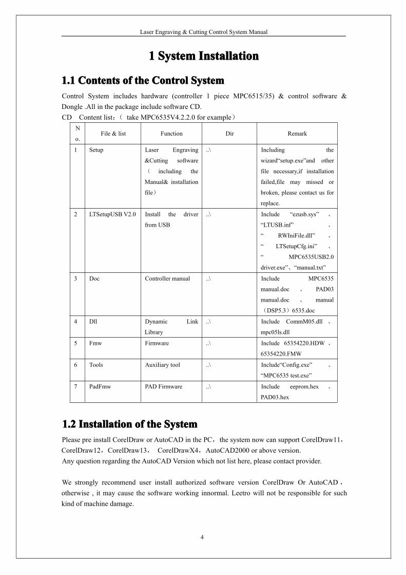
1.11.11.11.1 ContentsContentsContentsContents ofofofof thethethethe ControlControlControlControl SystemSystemSystemSystemControl System includes hardware (controller 1 piece MPC6515/35) & control software &Dongle .All in the package include software CD.CD Content list:( take MPC6535V4.2.2.0 for example)
N
o.File & list Function Dir Remark
1 Setup Laser Engraving
&Cutting software
( including the
Manual& installation
file)
..\ Including the
wizard“setup.exe”and other
file necessary,if installation
failed,file may missed or
broken, please contact us for
replace.
2 LTSetupUSB V2.0 Install the driver
from USB
..\ Include “ezusb.sys” 、
“LTUSB.inf” 、
“ RWIniFile.dll” 、
“ LTSetupCfg.ini” 、
“ MPC6535USB2.0
driver.exe”、“manual.txt”
3 Doc Controller manual ..\ Include MPC6535
manual.doc 、 PAD03
manual.doc 、 manual
(DSP5.3)6535.doc
4 Dll Dynamic Link
Library
..\ Include CommM05.dll 、
mpc05ls.dll
5 Fmw Firmware ..\ Include 65354220.HDW 、
65354220.FMW
6 Tools AuxiIiary tool ..\ Include“Config.exe” 、
“MPC6535 test.exe”
7 PadFmw PAD Firmware ..\ Include eeprom.hex 、
PAD03.hex
1.21.21.21.2 InstallationInstallationInstallationInstallation ofofofof thethethethe SystemSystemSystemSystemPlease pre install CorelDraw or AutoCAD in the PC,the system now can support CorelDraw11,CorelDraw12,CorelDraw13, CorelDrawX4,AutoCAD2000 or above version.Any question regarding the AutoCAD Version which not list here, please contact provider.
We strongly recommend user install authorized software version CorelDraw Or AutoCAD,
otherwise , it may cause the software working innormal. Leetro will not be responsible for suchkind of machine damage.
Laser Engraving & Cutting Control System Manual
5
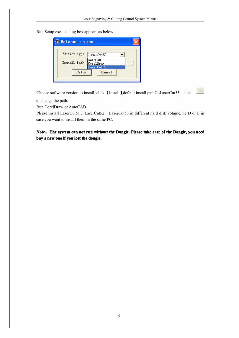
Run Setup.exe,dialog box appears as below:
Choose software version to install, click【Install】,default install pathC:\LaserCut53”, click
to change the path.Run CorelDraw or AutoCAD.Please install LaserCut51、LaserCut52、LaserCut53 in different hard disk volume, i.e D or E incase you want to install them in the same PC.
NoteNoteNoteNote:TheTheTheThe systemsystemsystemsystem cancancancan notnotnotnot runrunrunrun withoutwithoutwithoutwithout thethethethe Dongle.Dongle.Dongle.Dongle. PleasePleasePleasePlease taketaketaketake carecarecarecare ofofofof thethethethe Dongle,Dongle,Dongle,Dongle, youyouyouyou nnnneedeedeedeedbuybuybuybuy aaaa newnewnewnew oneoneoneone ifififif youyouyouyou lostlostlostlost thethethethe dongle.dongle.dongle.dongle.
Laser Engraving & Cutting Control System Manual
6
2222 CorelDrawCorelDrawCorelDrawCorelDraw OutputOutputOutputOutput EditionEditionEditionEdition
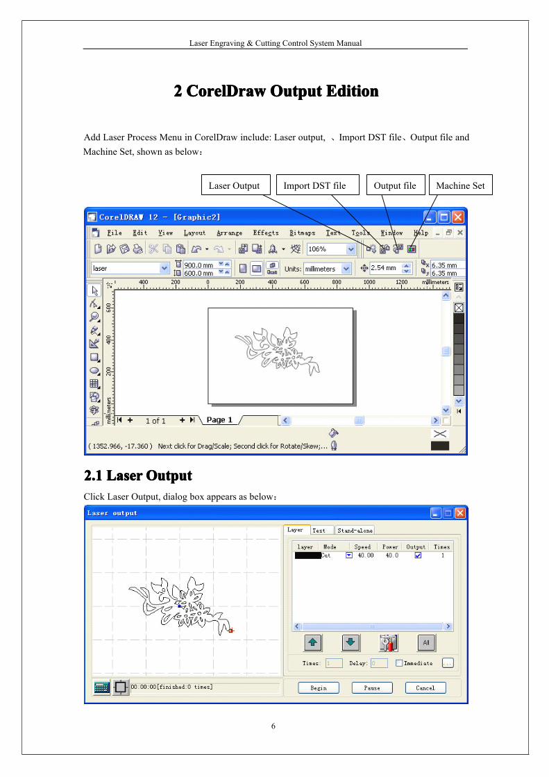
Add Laser Process Menu in CorelDraw include: Laser output, 、Import DST file、Output file andMachine Set, shown as below:
2.12.12.12.1 LaserLaserLaserLaser OutputOutputOutputOutputClick Laser Output, dialog box appears as below:
Laser Output Import DST file Output file Machine Set
Laser Engraving & Cutting Control System Manual
7
2.1.1 LayerSee also in Chapter 5。2.1.2 ManualSee also in Chapter 52.1.3 Procession File(Download Data)See also in Chapter 5。
2.1.4
CalculationCalculationCalculationCalculation: when Drawing or process parameter change, recommend to click to save the
parameter into procession file.
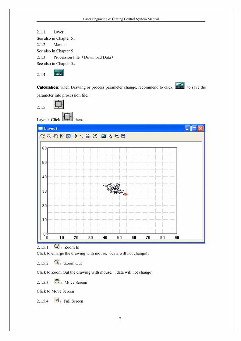
2.1.5
Layout. Click then,
2.1.5.1 :Zoom InClick to enlarge the drawing with mouse,(data will not change)。
2.1.5.2 :Zoom Out
Click to Zoom Out the drawing with mouse,(data will not change)
2.1.5.3 :Move Screen
Click to Move Screen
2.1.5.4 :Full Screen
Laser Engraving & Cutting Control System Manual
8
Click it to show full processing data range.
2.1.5.5 :Worktable Size
Click to show the whole worktable size/coordinate system and the full range of the
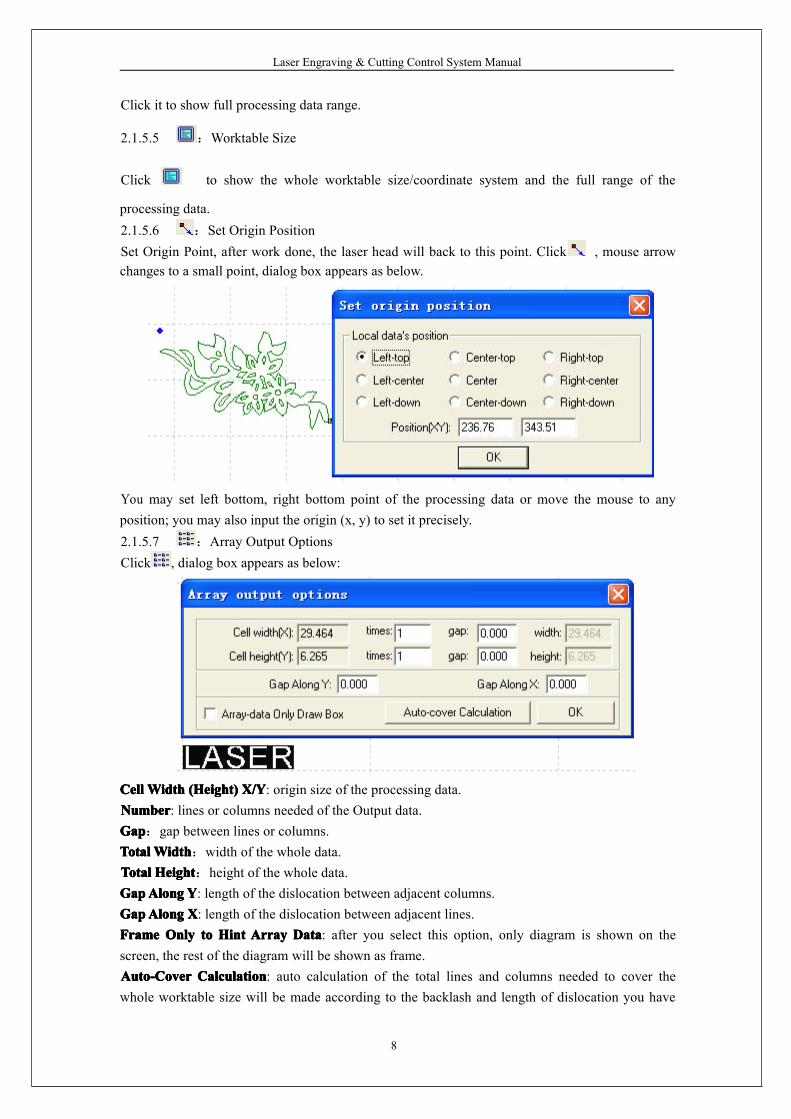
processing data.2.1.5.6 :Set Origin PositionSet Origin Point, after work done, the laser head will back to this point. Click , mouse arrowchanges to a small point, dialog box appears as below.
You may set left bottom, right bottom point of the processing data or move the mouse to anyposition; you may also input the origin (x, y) to set it precisely.2.1.5.7 :Array Output OptionsClick , dialog box appears as below:
CellCellCellCell WidthWidthWidthWidth (Height)(Height)(Height)(Height) X/YX/YX/YX/Y: origin size of the processing data.NumberNumberNumberNumber: lines or columns needed of the Output data.GapGapGapGap:gap between lines or columns.TotalTotalTotalTotalWidthWidthWidthWidth:width of the whole data.TotalTotalTotalTotal HeightHeightHeightHeight:height of the whole data.GapGapGapGapAlongAlongAlongAlong YYYY: length of the dislocation between adjacent columns.GapGapGapGapAlongAlongAlongAlong XXXX: length of the dislocation between adjacent lines.FrameFrameFrameFrame OnlyOnlyOnlyOnly totototo HintHintHintHint ArrayArrayArrayArray DataDataDataData: after you select this option, only diagram is shown on thescreen, the rest of the diagram will be shown as frame.Auto-CoverAuto-CoverAuto-CoverAuto-Cover CalculationCalculationCalculationCalculation: auto calculation of the total lines and columns needed to cover thewhole worktable size will be made according to the backlash and length of dislocation you have
Laser Engraving & Cutting Control System Manual
9
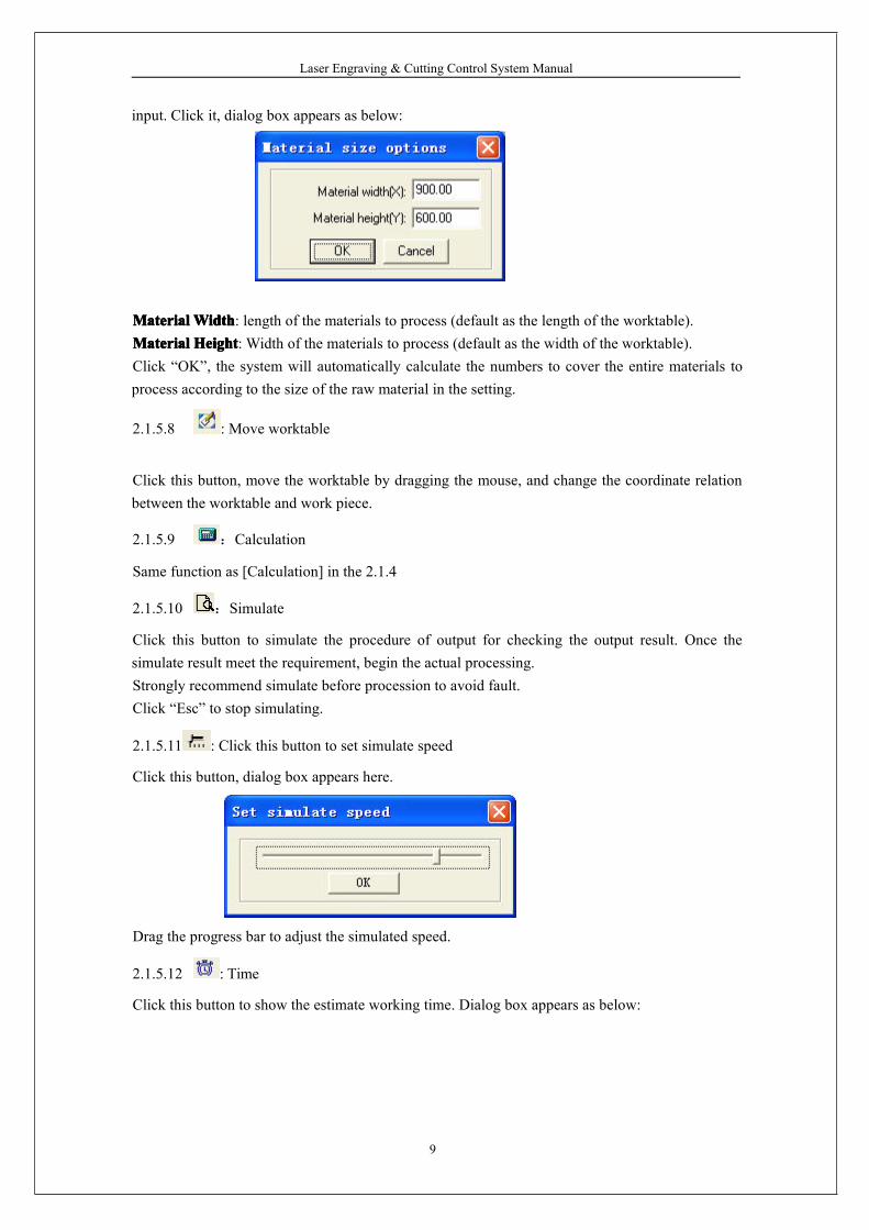
input. Click it, dialog box appears as below:
MaterialMaterialMaterialMaterial WidthWidthWidthWidth: length of the materials to process (default as the length of the worktable).MaterialMaterialMaterialMaterial HeightHeightHeightHeight: Width of the materials to process (default as the width of the worktable).Click “OK”, the system will automatically calculate the numbers to cover the entire materials toprocess according to the size of the raw material in the setting.
2.1.5.8 : Move worktable
Click this button, move the worktable by dragging the mouse, and change the coordinate relationbetween the worktable and work piece.
2.1.5.9 :Calculation
Same function as [Calculation] in the 2.1.4
2.1.5.10 :Simulate
Click this button to simulate the procedure of output for checking the output result. Once thesimulate result meet the requirement, begin the actual processing.Strongly recommend simulate before procession to avoid fault.Click “Esc” to stop simulating.
2.1.5.11 : Click this button to set simulate speed
Click this button, dialog box appears here.
Drag the progress bar to adjust the simulated speed.
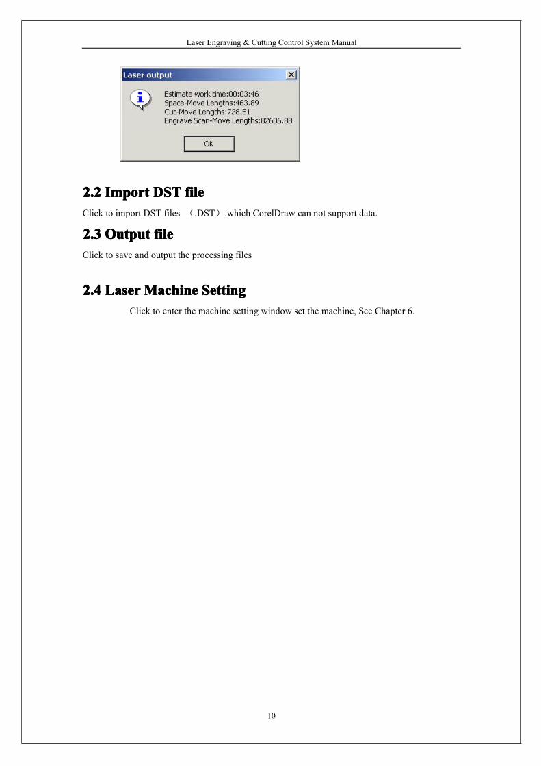
2.1.5.12 : Time
Click this button to show the estimate working time. Dialog box appears as below:
Laser Engraving & Cutting Control System Manual
10
2.22.22.22.2 ImportImportImportImport DSTDSTDSTDST filefilefilefileClick to import DST files (.DST).which CorelDraw can not support data.
2.32.32.32.3 OutputOutputOutputOutput filefilefilefileClick to save and output the processing files
2.42.42.42.4 LaserLaserLaserLaserMachineMachineMachineMachine SettingSettingSettingSettingClick to enter the machine setting window set the machine, See Chapter 6.
Laser Engraving & Cutting Control System Manual
11
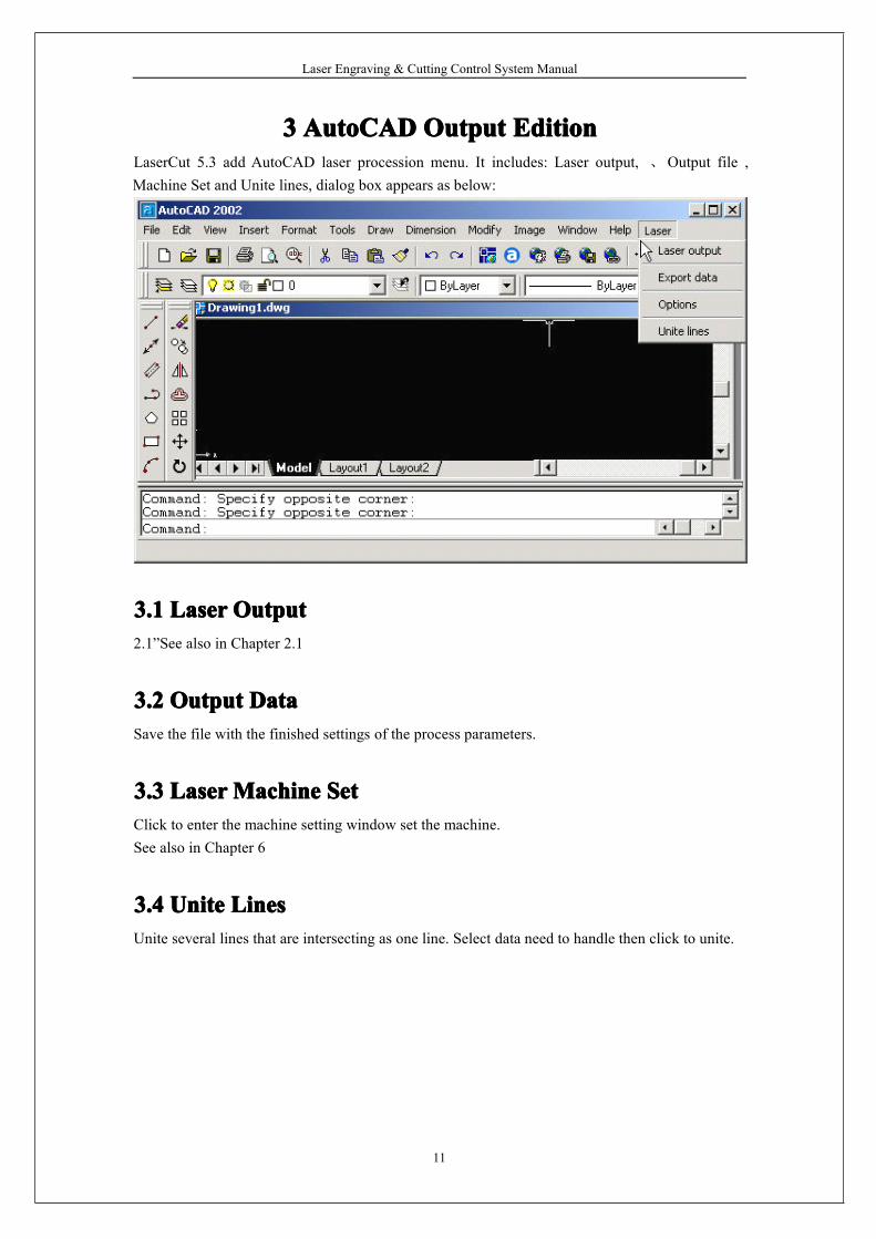
3333 AutoCADAutoCADAutoCADAutoCAD OutputOutputOutputOutput EditionEditionEditionEditionLaserCut 5.3 add AutoCAD laser procession menu. It includes: Laser output, 、Output file ,Machine Set and Unite lines, dialog box appears as below:
3.13.13.13.1 LaserLaserLaserLaser OutputOutputOutputOutput2.1”See also in Chapter 2.1
3.23.23.23.2 OutputOutputOutputOutput DataDataDataDataSave the file with the finished settings of the process parameters.
3.33.33.33.3 LaserLaserLaserLaserMachineMachineMachineMachine SetSetSetSetClick to enter the machine setting window set the machine.See also in Chapter 6
3.43.43.43.4 UniteUniteUniteUnite LinesLinesLinesLinesUnite several lines that are intersecting as one line. Select data need to handle then click to unite.
Laser Engraving & Cutting Control System Manual
12
4444 UniversalUniversalUniversalUniversal EditionEditionEditionEdition
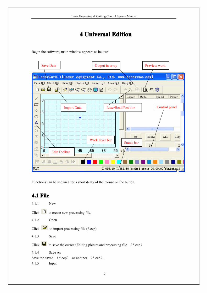
Begin the software, main window appears as below:
Functions can be shown after a short delay of the mouse on the button.
4.14.14.14.1 FileFileFileFile4.1.1 New
Click to create new processing file.
4.1.2 Open
Click to import processing file (*.ecp)
4.1.3 Save
Click to save the current Editing picture and processing file (*.ecp)
4.1.4 Save AsSave the saved (*.ecp) as another (*.ecp).4.1.5 Input
Import Data
Preview work
Control panel
Save Data Output in array
LaserHead Position
Edit Toolbar
Work layer barStatus bar
Laser Engraving & Cutting Control System Manual
13
Click to import software support file format, such as *.PLT、*.AI、*.DXF、*.DST、*.BMP、
NC code etc.4.1.6 Output
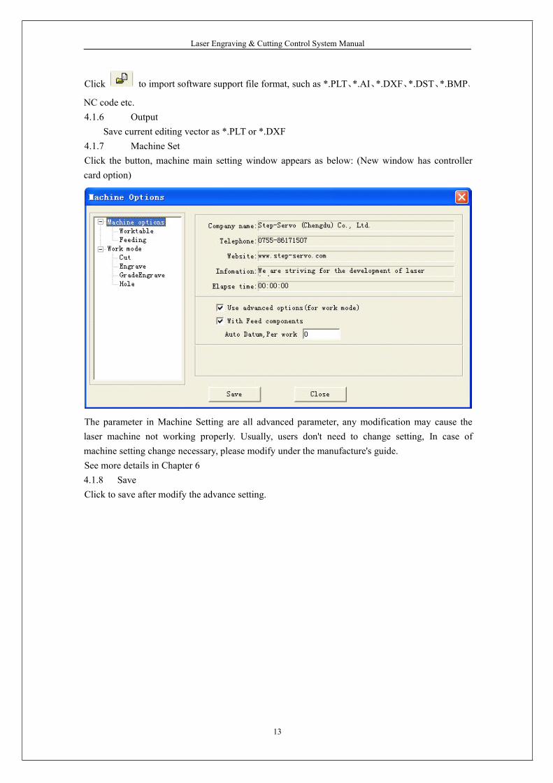
Save current editing vector as *.PLT or *.DXF4.1.7 Machine SetClick the button, machine main setting window appears as below: (New window has controllercard option)
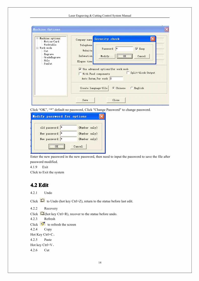
The parameter in Machine Setting are all advanced parameter, any modification may cause thelaser machine not working properly. Usually, users don't need to change setting, In case ofmachine setting change necessary, please modify under the manufacture's guide.See more details in Chapter 64.1.8 SaveClick to save after modify the advance setting.
Laser Engraving & Cutting Control System Manual
14
Click “OK”, “*” default no password, Click "Change Password" to change password.
Enter the new password in the new password, then need to input the password to save the file afterpassword modified.4.1.9 ExitClick to Exit the system
4.24.24.24.2 EditEditEditEdit4.2.1 Undo
Click to Undo (hot key Ctrl+Z), return to the statue before last edit.
4.2.2 RecoveryClick (hot key Ctrl+R), recover to the statue before undo.4.2.3 Refresh
Click to refresh the screen4.2.4 CopyHot Key Ctrl+C。4.2.5 PasteHot key Ctrl+V。4.2.6 Cut
Laser Engraving & Cutting Control System Manual
15
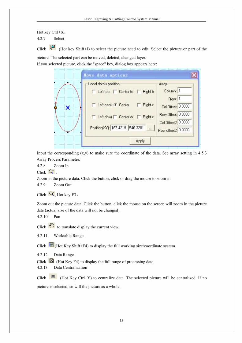
Hot key Ctrl+X。4.2.7 Select
Click (Hot key Shift+J) to select the picture need to edit. Select the picture or part of the
picture. The selected part can be moved, deleted, changed layer.If you selected picture, click the "space" key, dialog box appears here:
Input the corresponding (x,y) to make sure the coordinate of the data. See array setting in 4.5.3Array Process Parameter.4.2.8 Zoom InClick 。
Zoom in the picture data. Click the button, click or drag the mouse to zoom in.4.2.9 Zoom Out
Click , Hot key F3。
Zoom out the picture data. Click the button, click the mouse on the screen will zoom in the picturedate (actual size of the data will not be changed).4.2.10 Pan
Click to translate display the current view.
4.2.11 Worktable Range
Click (Hot Key Shift+F4) to display the full working size/coordinate system.
4.2.12 Data Range
Click (Hot Key F4) to display the full range of processing data.4.2.13 Data Centralization
Click (Hot Key Ctrl+Y) to centralize data. The selected picture will be centralized. If no
picture is selected, so will the picture as a whole.
Laser Engraving & Cutting Control System Manual
16
4.34.34.34.3 DrawingDrawingDrawingDrawing4.3.1 Line
Click to draw a line. After clicking the button, dragging the mouse on the screen will draw a
line as will. Press “Ctrl” at the same time as you drag the mouse will draw a horizontal line.4.3.2 Rectangle
Click to draw a rectangle. After clicking the button, dragging the mouse on the screen will
draw a rectangle with any size. Press “Ctrl” at the same time as you drag the mouse wil draw asquare.4.3.3 Multipoint line
Click to draw a multipoint line with any size by dragging and clicking the mouse on the
screen. Press “C”, ends of the line will meet automatically.4.3.4 EllipseClick to draw a Ellipse by dragging and clicking the mouse on the screen. Press “Ctrl” at thesame time as you drag the mouse will draw a perfect circle.4.3.5 Bezier Curve
Click to draw a Bezier Curve by dragging and clicking the mouse on the screen.
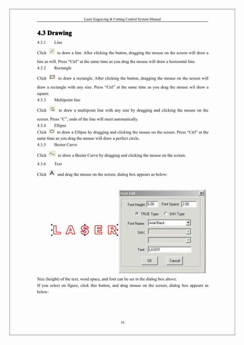
4.3.6 Text
Click and drag the mouse on the screen, dialog box appears as below:
Size (height) of the text, word space, and font can be set in the dialog box above.If you select on figure, click this button, and drag mouse on the screen, dialog box appears asbelow:
Laser Engraving & Cutting Control System Manual
17
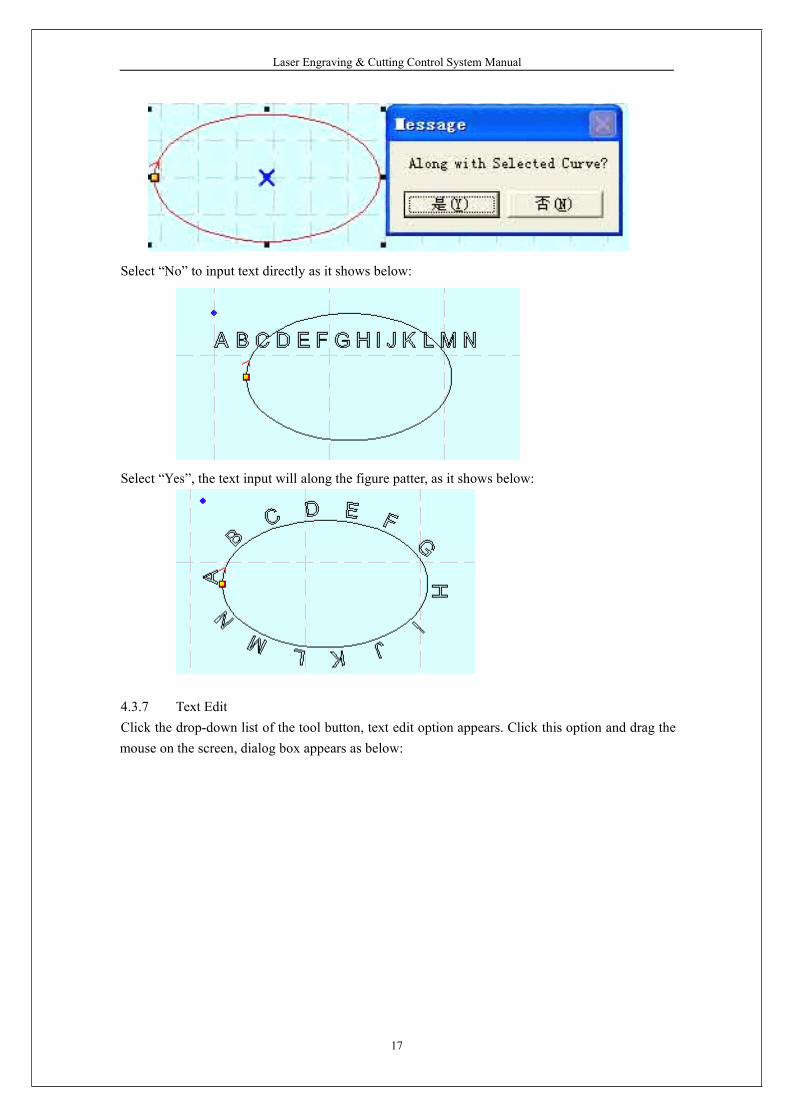
Select “No” to input text directly as it shows below:
Select “Yes”, the text input will along the figure patter, as it shows below:
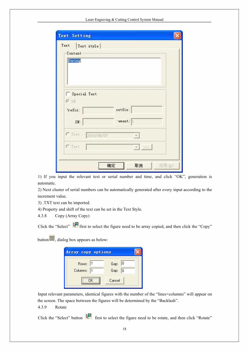
4.3.7 Text EditClick the drop-down list of the tool button, text edit option appears. Click this option and drag themouse on the screen, dialog box appears as below:
Laser Engraving & Cutting Control System Manual
18
1) If you input the relevant text or serial number and time, and click “OK”, generation isautomatic.2) Next cluster of serial numbers can be automatically generated after every input according to theincrement value.3) .TXT text can be imported.4) Property and shift of the text can be set in the Text Style.4.3.8 Copy (Array Copy)
Click the “Select” first to select the figure need to be array copied, and then click the “Copy”
button , dialog box appears as below:
Input relevant parameters, identical figures with the number of the “lines×columns” will appear onthe screen. The space between the figures will be determined by the “Backlash”.4.3.9 Rotate
Click the “Select” button first to select the figure need to be rotate, and then click “Rotate”
Laser Engraving & Cutting Control System Manual
19
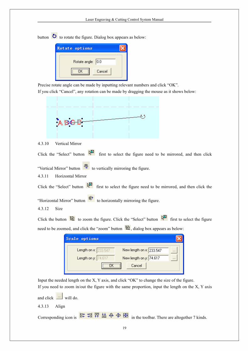
button to rotate the figure. Dialog box appears as below:
Precise rotate angle can be made by inputting relevant numbers and click “OK”.If you click “Cancel”, any rotation can be made by dragging the mouse as it shows below:
4.3.10 Vertical Mirror
Click the “Select” button first to select the figure need to be mirrored, and then click
“Vertical Mirror” button to vertically mirroring the figure.
4.3.11 Horizontal Mirror
Click the “Select” button first to select the figure need to be mirrored, and then click the
“Horizontal Mirror” button to horizontally mirroring the figure.
4.3.12 Size
Click the button to zoom the figure. Click the “Select” button first to select the figure
need to be zoomed, and click the “zoom” button , dialog box appears as below:
Input the needed length on the X, Y axis, and click “OK” to change the size of the figure.If you need to zoom in/out the figure with the same proportion, input the length on the X, Y axis
and click will do.
4.3.13 Align
Corresponding icon is in the toolbar. There are altogether 7 kinds.
Laser Engraving & Cutting Control System Manual
20
4.3.14 Node Edit
Click the button to edit the node of the figure selected. If you click the button, nods on the
figure selected will be shown in the form of small box. It appears as below:
Move the mouse on the node and drag the mouse will change the shape of the figure.Move the mouse on the figure, the mouse will change into cross, double click the mouse willincrease a new node. If you want to delete a node, move the mouse to the node and click “Delete”.4.3.15 ClipClick “Clip” to clip the figure. Click the button, move the mouse to the outline of the figure, andclick the mouse to clip the figure selected. This function is mainly used to process DST files.4.3.16 Layer property
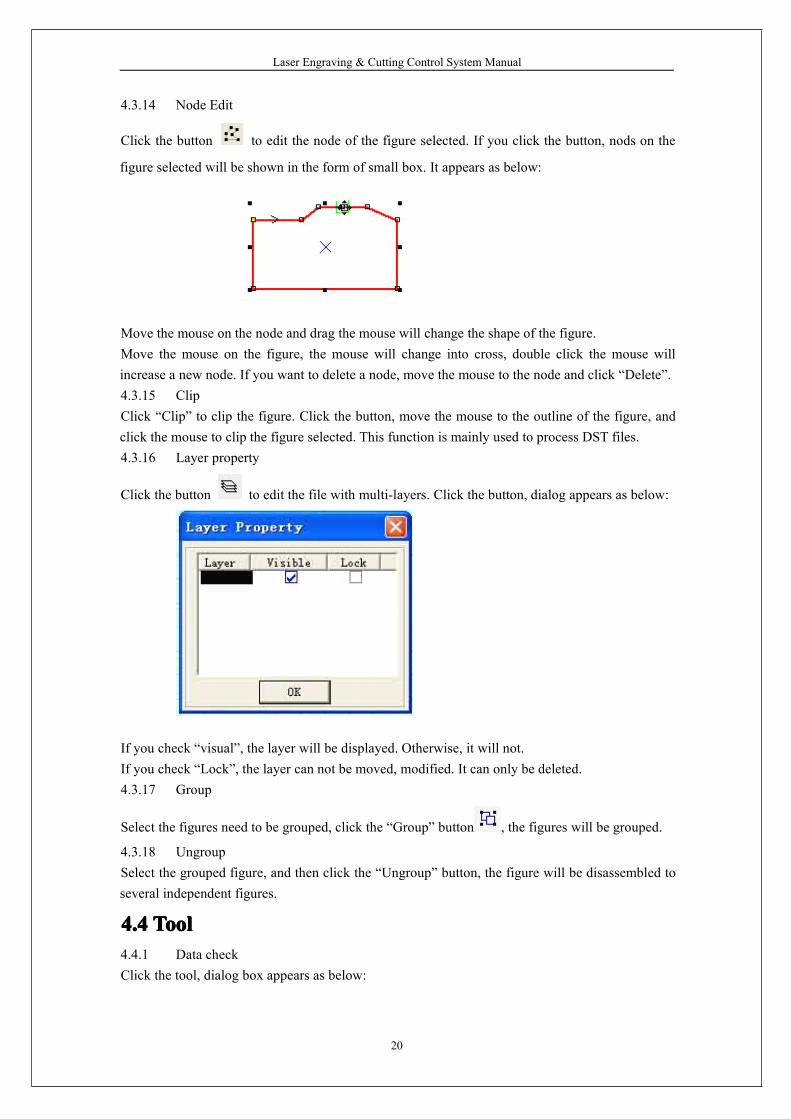
Click the button to edit the file with multi-layers. Click the button, dialog appears as below:
If you check “visual”, the layer will be displayed. Otherwise, it will not.If you check “Lock”, the layer can not be moved, modified. It can only be deleted.4.3.17 Group
Select the figures need to be grouped, click the “Group” button , the figures will be grouped.
4.3.18 UngroupSelect the grouped figure, and then click the “Ungroup” button, the figure will be disassembled toseveral independent figures.
4.44.44.44.4 ToolToolToolTool4.4.1 Data checkClick the tool, dialog box appears as below:
Laser Engraving & Cutting Control System Manual
21
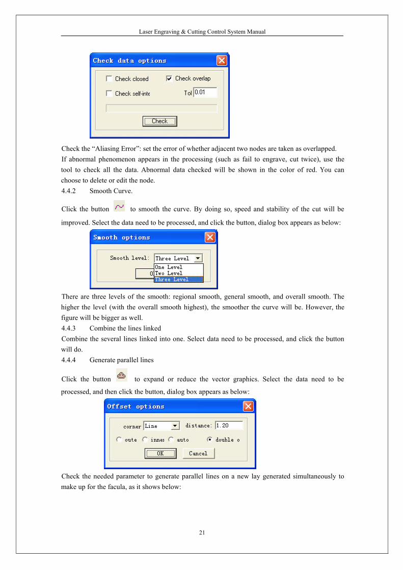
Check the “Aliasing Error”: set the error of whether adjacent two nodes are taken as overlapped.If abnormal phenomenon appears in the processing (such as fail to engrave, cut twice), use thetool to check all the data. Abnormal data checked will be shown in the color of red. You canchoose to delete or edit the node.4.4.2 Smooth Curve.
Click the button to smooth the curve. By doing so, speed and stability of the cut will be
improved. Select the data need to be processed, and click the button, dialog box appears as below:
There are three levels of the smooth: regional smooth, general smooth, and overall smooth. Thehigher the level (with the overall smooth highest), the smoother the curve will be. However, thefigure will be bigger as well.4.4.3 Combine the lines linkedCombine the several lines linked into one. Select data need to be processed, and click the buttonwill do.4.4.4 Generate parallel lines
Click the button to expand or reduce the vector graphics. Select the data need to be
processed, and then click the button, dialog box appears as below:
Check the needed parameter to generate parallel lines on a new lay generated simultaneously tomake up for the facula, as it shows below:
Laser Engraving & Cutting Control System Manual
22
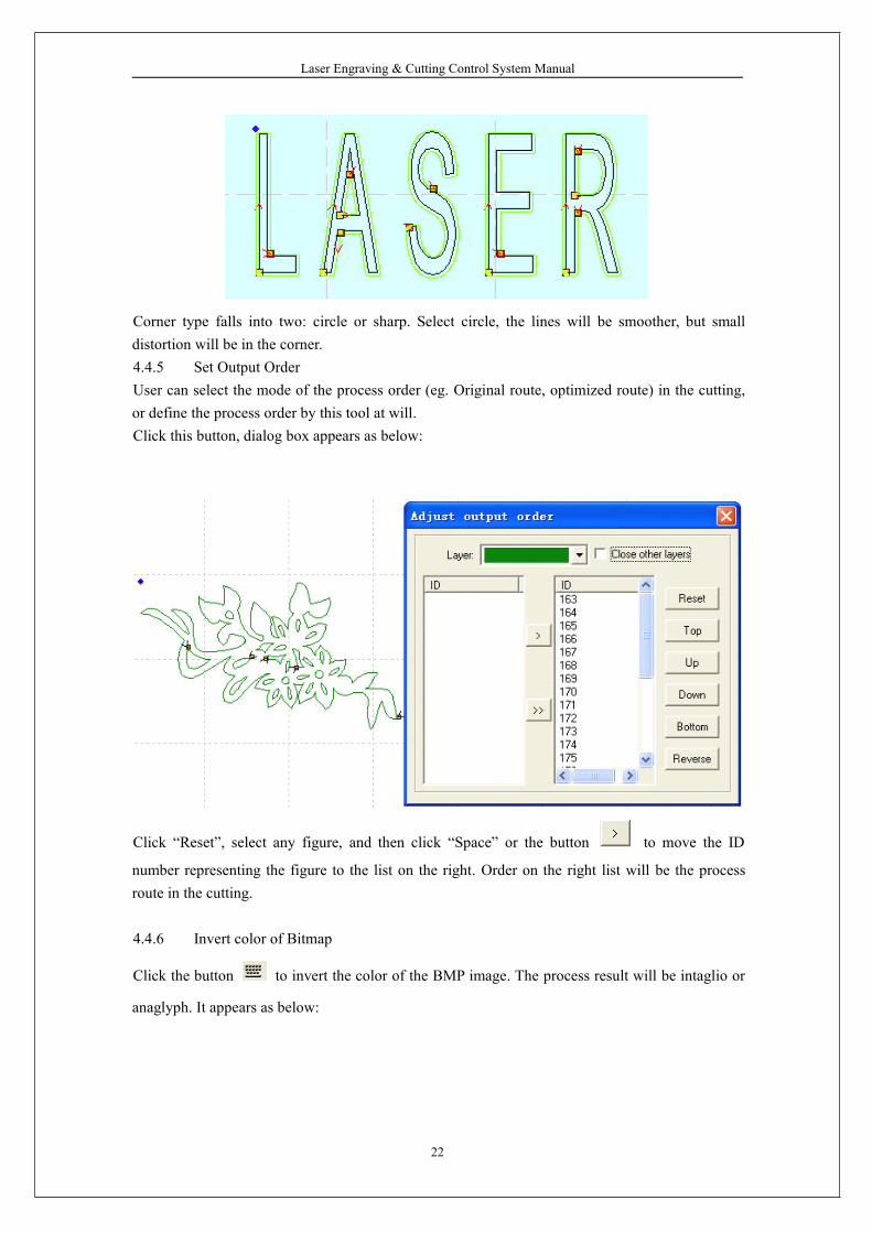
Corner type falls into two: circle or sharp. Select circle, the lines will be smoother, but smalldistortion will be in the corner.4.4.5 Set Output OrderUser can select the mode of the process order (eg. Original route, optimized route) in the cutting,or define the process order by this tool at will.Click this button, dialog box appears as below:
Click “Reset”, select any figure, and then click “Space” or the button to move the ID
number representing the figure to the list on the right. Order on the right list will be the processroute in the cutting.
4.4.6 Invert color of Bitmap
Click the button to invert the color of the BMP image. The process result will be intaglio or
anaglyph. It appears as below:
Laser Engraving & Cutting Control System Manual
23
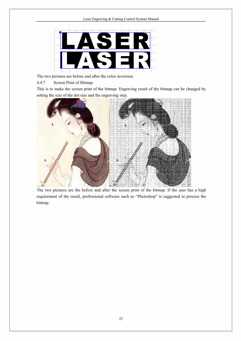
The two pictures are before and after the color inversion.4.4.7 Screen Print of BitmapThis is to make the screen print of the bitmap. Engraving result of the bitmap can be changed bysetting the size of the dot size and the engraving step.
The two pictures are the before and after the screen print of the bitmap. If the user has a highrequirement of the result, professional software such as “Photoshop” is suggested to process thebitmap.
Laser Engraving & Cutting Control System Manual
24
4.54.54.54.5 LaserLaserLaserLaser processingprocessingprocessingprocessing4.5.1 Define First Cut
The corresponding icon is .
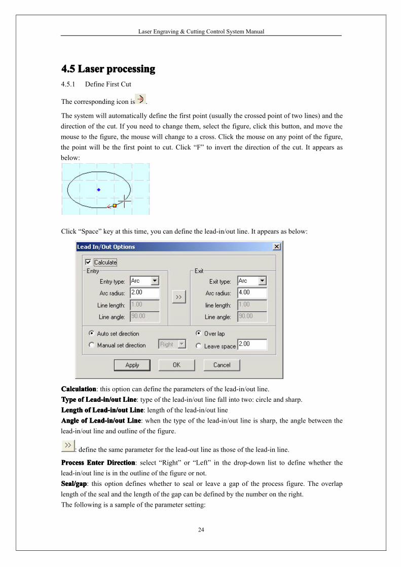
The system will automatically define the first point (usually the crossed point of two lines) and thedirection of the cut. If you need to change them, select the figure, click this button, and move themouse to the figure, the mouse will change to a cross. Click the mouse on any point of the figure,the point will be the first point to cut. Click “F” to invert the direction of the cut. It appears asbelow:
Click “Space” key at this time, you can define the lead-in/out line. It appears as below:
CalculationCalculationCalculationCalculation: this option can define the parameters of the lead-in/out line.TypeTypeTypeType ofofofof Lead-in/outLead-in/outLead-in/outLead-in/out LineLineLineLine: type of the lead-in/out line fall into two: circle and sharp.LengthLengthLengthLength ofofofof Lead-in/outLead-in/outLead-in/outLead-in/out LineLineLineLine: length of the lead-in/out lineAngleAngleAngleAngle ofofofof Lead-in/outLead-in/outLead-in/outLead-in/out LineLineLineLine: when the type of the lead-in/out line is sharp, the angle between thelead-in/out line and outline of the figure.
: define the same parameter for the lead-out line as those of the lead-in line.
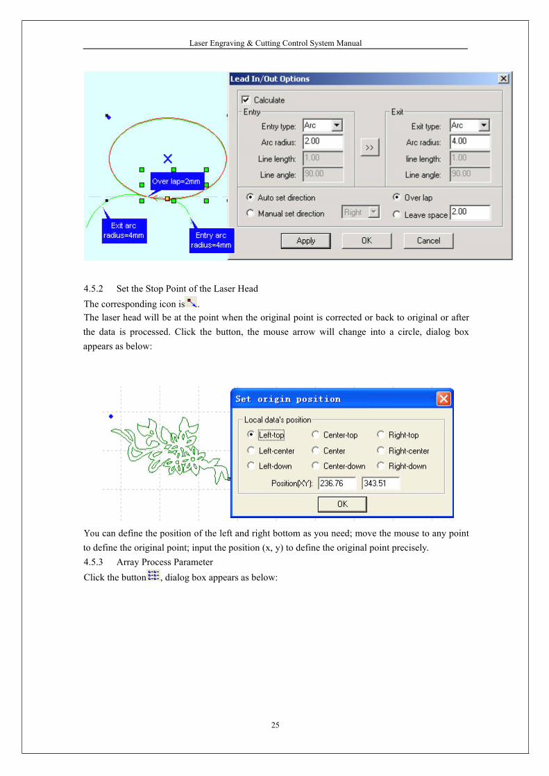
ProcessProcessProcessProcess EnterEnterEnterEnter DirectionDirectionDirectionDirection: select “Right” or “Left” in the drop-down list to define whether thelead-in/out line is in the outline of the figure or not.Seal/gapSeal/gapSeal/gapSeal/gap: this option defines whether to seal or leave a gap of the process figure. The overlaplength of the seal and the length of the gap can be defined by the number on the right.The following is a sample of the parameter setting:
Laser Engraving & Cutting Control System Manual
25
4.5.2 Set the Stop Point of the Laser HeadThe corresponding icon is .The laser head will be at the point when the original point is corrected or back to original or afterthe data is processed. Click the button, the mouse arrow will change into a circle, dialog boxappears as below:
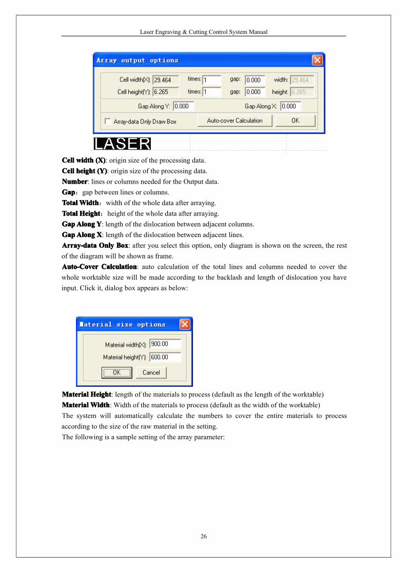
You can define the position of the left and right bottom as you need; move the mouse to any pointto define the original point; input the position (x, y) to define the original point precisely.4.5.3 Array Process ParameterClick the button , dialog box appears as below:
Laser Engraving & Cutting Control System Manual
26
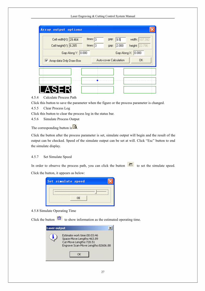
CellCellCellCell widthwidthwidthwidth (X)(X)(X)(X): origin size of the processing data.CellCellCellCell heightheightheightheight (Y)(Y)(Y)(Y): origin size of the processing data.NumberNumberNumberNumber: lines or columns needed for the Output data.GapGapGapGap:gap between lines or columns.TotalTotalTotalTotalWidthWidthWidthWidth:width of the whole data after arraying.TotalTotalTotalTotal HeightHeightHeightHeight:height of the whole data after arraying.GapGapGapGapAlongAlongAlongAlong YYYY: length of the dislocation between adjacent columns.GapGapGapGapAlongAlongAlongAlong XXXX: length of the dislocation between adjacent lines.Array-dataArray-dataArray-dataArray-data OnlyOnlyOnlyOnly BoxBoxBoxBox: after you select this option, only diagram is shown on the screen, the restof the diagram will be shown as frame.Auto-CoverAuto-CoverAuto-CoverAuto-Cover CalculationCalculationCalculationCalculation: auto calculation of the total lines and columns needed to cover thewhole worktable size will be made according to the backlash and length of dislocation you haveinput. Click it, dialog box appears as below:
MaterialMaterialMaterialMaterial HeightHeightHeightHeight: length of the materials to process (default as the length of the worktable)MaterialMaterialMaterialMaterial WidthWidthWidthWidth: Width of the materials to process (default as the width of the worktable)The system will automatically calculate the numbers to cover the entire materials to processaccording to the size of the raw material in the setting.The following is a sample setting of the array parameter:
Laser Engraving & Cutting Control System Manual
27
4.5.4 Calculate Process PathClick this button to save the parameter when the figure or the process parameter is changed.4.5.5 Clear Process LogClick this button to clear the process log in the status bar.4.5.6 Simulate Process Output
The corresponding button is .
Click the button after the process parameter is set, simulate output will begin and the result of theoutput can be checked. Speed of the simulate output can be set at will. Click “Esc” button to endthe simulate display.
4.5.7 Set Simulate Speed
In order to observe the process path, you can click the button to set the simulate speed.
Click the button, it appears as below:
4.5.8 Simulate Operating Time
Click the button to show information as the estimated operating time.
Laser Engraving & Cutting Control System Manual
28
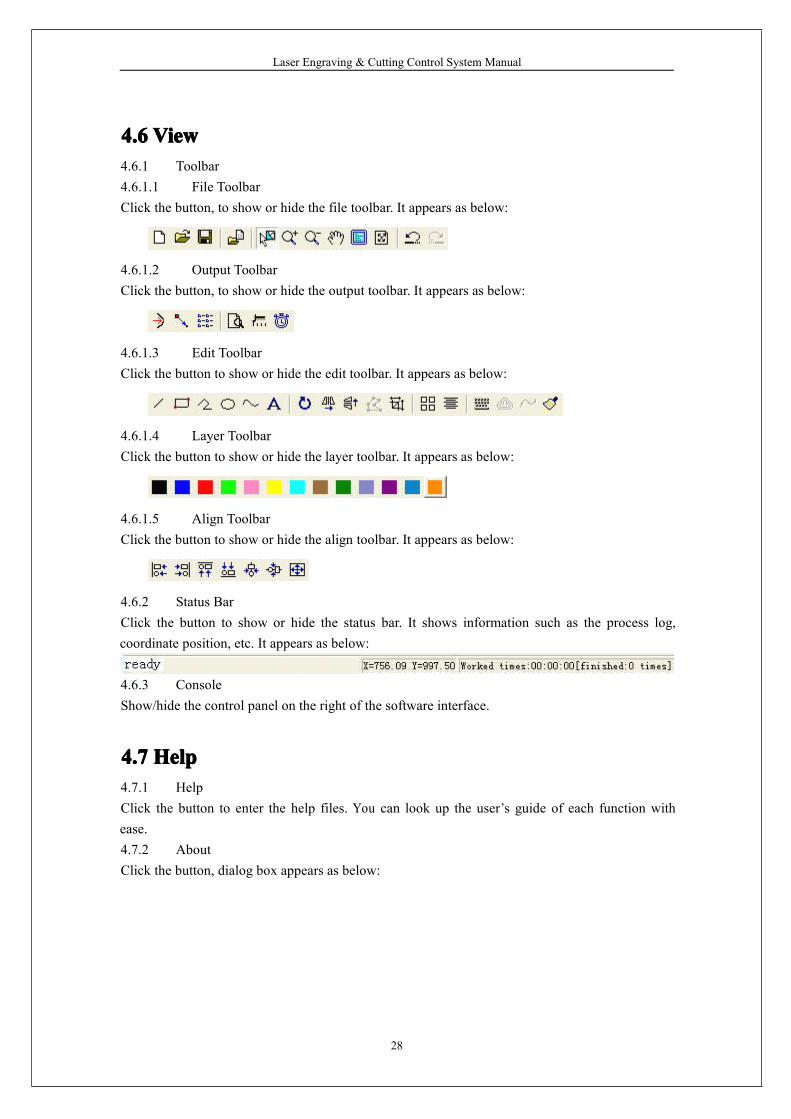
4.64.64.64.6 ViewViewViewView4.6.1 Toolbar4.6.1.1 File ToolbarClick the button, to show or hide the file toolbar. It appears as below:
4.6.1.2 Output ToolbarClick the button, to show or hide the output toolbar. It appears as below:
4.6.1.3 Edit ToolbarClick the button to show or hide the edit toolbar. It appears as below:
4.6.1.4 Layer ToolbarClick the button to show or hide the layer toolbar. It appears as below:
4.6.1.5 Align ToolbarClick the button to show or hide the align toolbar. It appears as below:
4.6.2 Status BarClick the button to show or hide the status bar. It shows information such as the process log,coordinate position, etc. It appears as below:
4.6.3 ConsoleShow/hide the control panel on the right of the software interface.
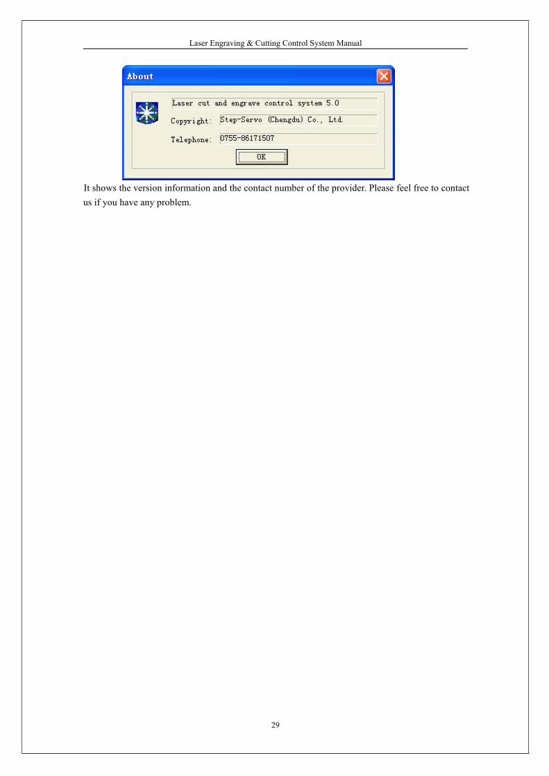
4.74.74.74.7 HelpHelpHelpHelp4.7.1 HelpClick the button to enter the help files. You can look up the user’s guide of each function withease.4.7.2 AboutClick the button, dialog box appears as below:
Laser Engraving & Cutting Control System Manual
29
It shows the version information and the contact number of the provider. Please feel free to contactus if you have any problem.
Laser Engraving & Cutting Control System Manual
30
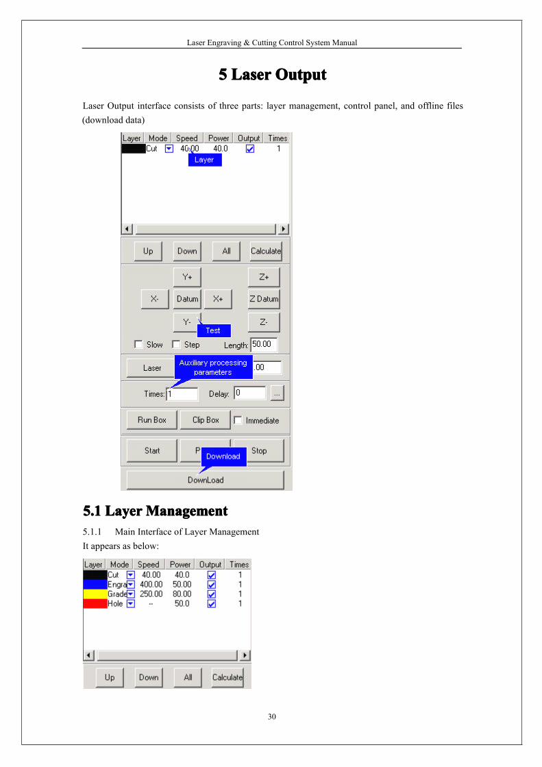
5555 LaserLaserLaserLaser OutputOutputOutputOutput
Laser Output interface consists of three parts: layer management, control panel, and offline files(download data)
5.15.15.15.1 LayerLayerLayerLayerManagementManagementManagementManagement5.1.1 Main Interface of Layer ManagementIt appears as below:
Laser Engraving & Cutting Control System Manual
31
Process sequence is from the bottom of the list up. If you want to change the process sequence,
simply check the line and click or will do.
If there are several layers in the process data, check one line in the list and click willmake the process parameter of other layers same with the one checked.
Click the button to save after figure or process parameters are changed.Process pattern can be selected in the drop-down list of the “Mode” column. It appears as below:
You can choose to output the layer or not in the “Output” column, is to output,
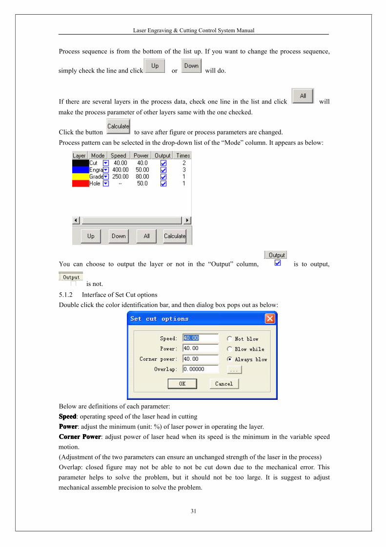
is not.5.1.2 Interface of Set Cut optionsDouble click the color identification bar, and then dialog box pops out as below:
Below are definitions of each parameter:SpeedSpeedSpeedSpeed: operating speed of the laser head in cuttingPowerPowerPowerPower: adjust the minimum (unit: %) of laser power in operating the layer.CornerCornerCornerCorner PowerPowerPowerPower: adjust power of laser head when its speed is the minimum in the variable speedmotion.(Adjustment of the two parameters can ensure an unchanged strength of the laser in the process)Overlap: closed figure may not be able to not be cut down due to the mechanical error. Thisparameter helps to solve the problem, but it should not be too large. It is suggest to adjustmechanical assemble precision to solve the problem.
Laser Engraving & Cutting Control System Manual
32
NotNotNotNot BlowBlowBlowBlow: not to blow in the process.BlowBlowBlowBlow whilewhilewhilewhile: blow when the laser in on, stop blowing when the laser is off. This function needshardware support.AlwaysAlwaysAlwaysAlways blowblowblowblow: begin to blow at the moment laser begin to move to the end of the process. Thisfunction needs hardware support.
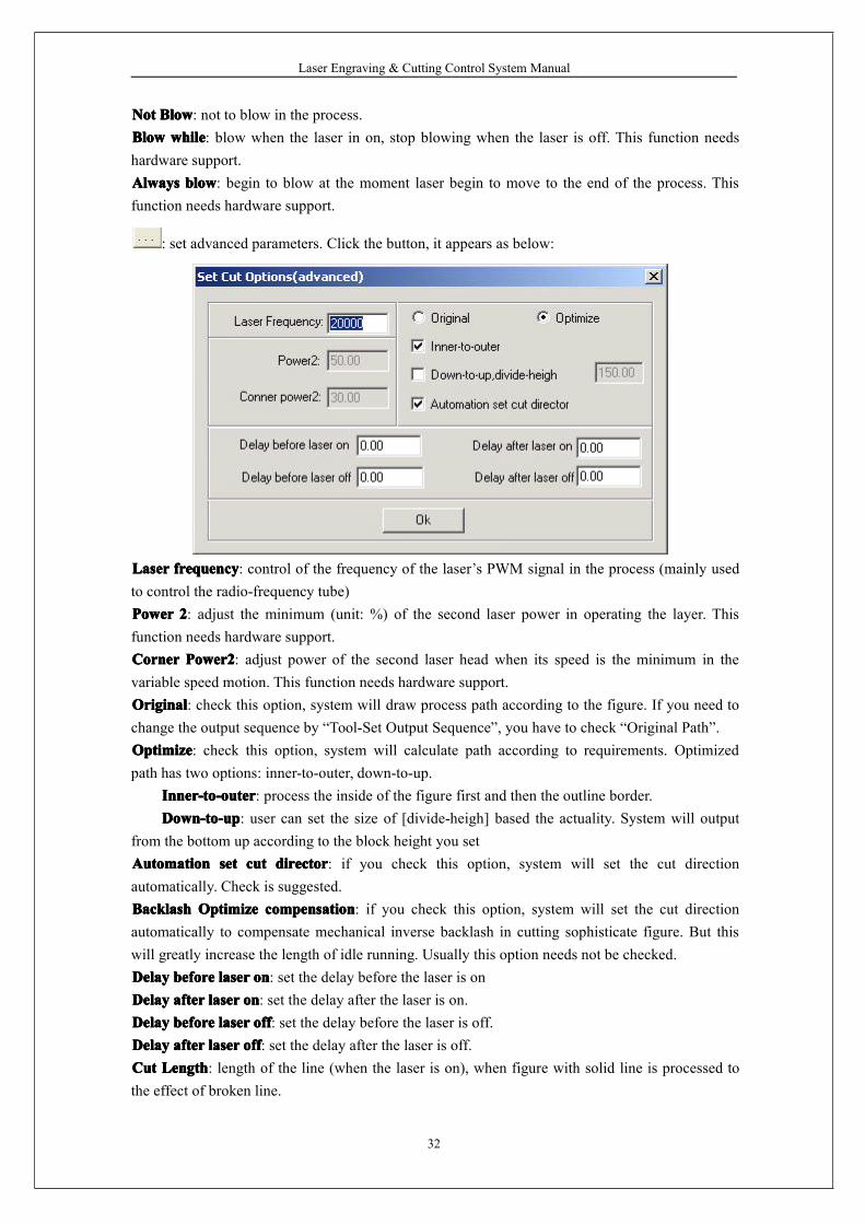
: set advanced parameters. Click the button, it appears as below:
LaserLaserLaserLaser frequencyfrequencyfrequencyfrequency: control of the frequency of the laser’s PWM signal in the process (mainly usedto control the radio-frequency tube)PowerPowerPowerPower 2222: adjust the minimum (unit: %) of the second laser power in operating the layer. Thisfunction needs hardware support.CornerCornerCornerCorner Power2Power2Power2Power2: adjust power of the second laser head when its speed is the minimum in thevariable speed motion. This function needs hardware support.OriginalOriginalOriginalOriginal: check this option, system will draw process path according to the figure. If you need tochange the output sequence by “Tool-Set Output Sequence”, you have to check “Original Path”.OptimizeOptimizeOptimizeOptimize: check this option, system will calculate path according to requirements. Optimizedpath has two options: inner-to-outer, down-to-up.
Inner-to-outerInner-to-outerInner-to-outerInner-to-outer: process the inside of the figure first and then the outline border.Down-to-upDown-to-upDown-to-upDown-to-up: user can set the size of [divide-heigh] based the actuality. System will output
from the bottom up according to the block height you setAutomationAutomationAutomationAutomation setsetsetset cutcutcutcut directordirectordirectordirector: if you check this option, system will set the cut directionautomatically. Check is suggested.BacklashBacklashBacklashBacklash OptimizeOptimizeOptimizeOptimize compensationcompensationcompensationcompensation: if you check this option, system will set the cut directionautomatically to compensate mechanical inverse backlash in cutting sophisticate figure. But thiswill greatly increase the length of idle running. Usually this option needs not be checked.DelayDelayDelayDelay beforebeforebeforebefore laserlaserlaserlaser onononon: set the delay before the laser is onDelayDelayDelayDelay afterafterafterafter laserlaserlaserlaser onononon: set the delay after the laser is on.DelayDelayDelayDelay beforebeforebeforebefore laserlaserlaserlaser offoffoffoff: set the delay before the laser is off.DelayDelayDelayDelay afterafterafterafter laserlaserlaserlaser offoffoffoff: set the delay after the laser is off.CutCutCutCut LengthLengthLengthLength: length of the line (when the laser is on), when figure with solid line is processed tothe effect of broken line.
Laser Engraving & Cutting Control System Manual
33
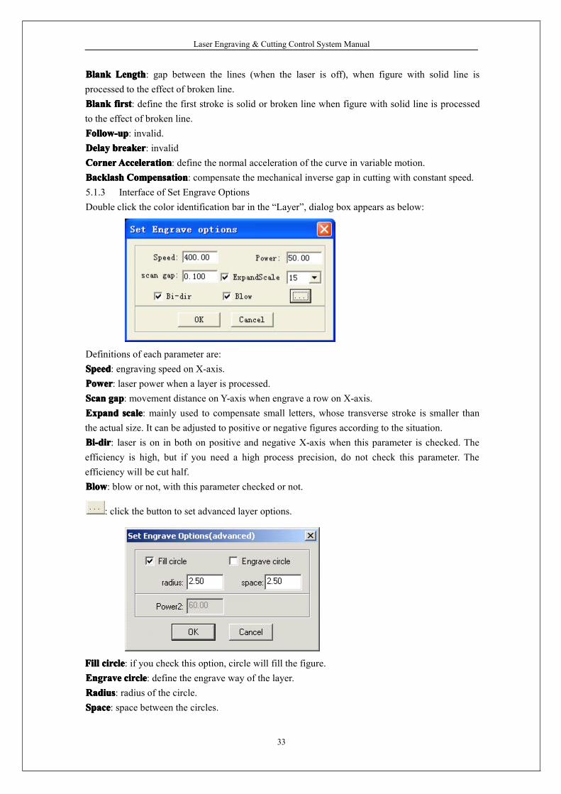
BlankBlankBlankBlank LengthLengthLengthLength: gap between the lines (when the laser is off), when figure with solid line isprocessed to the effect of broken line.BlankBlankBlankBlank firstfirstfirstfirst: define the first stroke is solid or broken line when figure with solid line is processedto the effect of broken line.Follow-upFollow-upFollow-upFollow-up: invalid.DelayDelayDelayDelay breakerbreakerbreakerbreaker: invalidCornerCornerCornerCornerAccelerationAccelerationAccelerationAcceleration: define the normal acceleration of the curve in variable motion.BacklashBacklashBacklashBacklash CompensationCompensationCompensationCompensation: compensate the mechanical inverse gap in cutting with constant speed.5.1.3 Interface of Set Engrave OptionsDouble click the color identification bar in the “Layer”, dialog box appears as below:
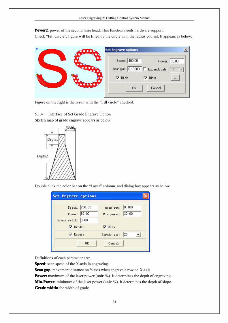
Definitions of each parameter are:SpeedSpeedSpeedSpeed: engraving speed on X-axis.PowerPowerPowerPower: laser power when a layer is processed.ScanScanScanScan gapgapgapgap: movement distance on Y-axis when engrave a row on X-axis.ExpandExpandExpandExpand scalescalescalescale: mainly used to compensate small letters, whose transverse stroke is smaller thanthe actual size. It can be adjusted to positive or negative figures according to the situation.Bi-dirBi-dirBi-dirBi-dir: laser is on in both on positive and negative X-axis when this parameter is checked. Theefficiency is high, but if you need a high process precision, do not check this parameter. Theefficiency will be cut half.BlowBlowBlowBlow: blow or not, with this parameter checked or not.
: click the button to set advanced layer options.
FillFillFillFill circlecirclecirclecircle: if you check this option, circle will fill the figure.EngraveEngraveEngraveEngrave circlecirclecirclecircle: define the engrave way of the layer.RadiusRadiusRadiusRadius: radius of the circle.SpaceSpaceSpaceSpace: space between the circles.
Laser Engraving & Cutting Control System Manual
34
Power2Power2Power2Power2: power of the second laser head. This function needs hardware support.Check “Fill Circle”, figure will be filled by the circle with the radius you set. It appears as below:
Figure on the right is the result with the “Fill circle” checked.
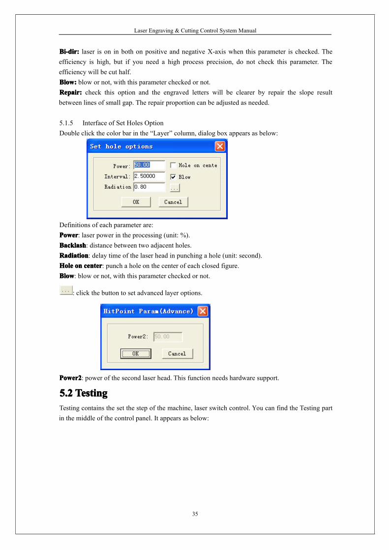
5.1.4 Interface of Set Grade Engrave OptionSketch map of grade engrave appears as below:
Double click the color bar on the “Layer” column, and dialog box appears as below:
Definitions of each parameter are:SpeedSpeedSpeedSpeed: scan speed of the X-axis in engraving.ScanScanScanScan gapgapgapgap: movement distance on Y-axis when engrave a row on X-axis.Power:Power:Power:Power:maximum of the laser power (unit: %). It determines the depth of engraving.Min-Power:Min-Power:Min-Power:Min-Power:minimum of the laser power (unit: %). It determines the depth of slope.Grade-width:Grade-width:Grade-width:Grade-width: the width of grade.
Laser Engraving & Cutting Control System Manual
35
Bi-dir:Bi-dir:Bi-dir:Bi-dir: laser is on in both on positive and negative X-axis when this parameter is checked. Theefficiency is high, but if you need a high process precision, do not check this parameter. Theefficiency will be cut half.Blow:Blow:Blow:Blow: blow or not, with this parameter checked or not.Repair:Repair:Repair:Repair: check this option and the engraved letters will be clearer by repair the slope resultbetween lines of small gap. The repair proportion can be adjusted as needed.
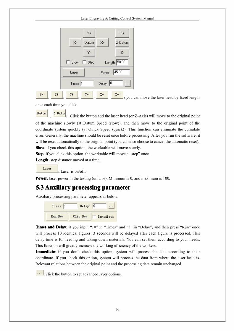
5.1.5 Interface of Set Holes OptionDouble click the color bar in the “Layer” column, dialog box appears as below:
Definitions of each parameter are:PowerPowerPowerPower: laser power in the processing (unit: %).BacklashBacklashBacklashBacklash: distance between two adjacent holes.RadiationRadiationRadiationRadiation: delay time of the laser head in punching a hole (unit: second).HoleHoleHoleHole onononon centercentercentercenter: punch a hole on the center of each closed figure.BlowBlowBlowBlow: blow or not, with this parameter checked or not.
: click the button to set advanced layer options.
Power2Power2Power2Power2: power of the second laser head. This function needs hardware support.
5.25.25.25.2 TestingTestingTestingTestingTesting contains the set the step of the machine, laser switch control. You can find the Testing partin the middle of the control panel. It appears as below:
Laser Engraving & Cutting Control System Manual
36
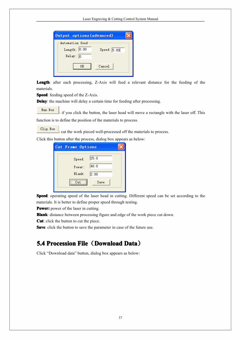
, , , , , :you can move the laser head by fixed length
once each time you click.
, :Click the button and the laser head (or Z-Axis) will move to the original point
of the machine slowly (at Datum Speed (slow)), and then move to the original point of thecoordinate system quickly (at Quick Speed (quick)). This function can eliminate the cumulateerror. Generally, the machine should be reset once before processing. After you run the software, itwill be reset automatically to the original point (you can also choose to cancel the automatic reset).SlowSlowSlowSlow: if you check this option, the worktable will move slowly.StepStepStepStep: if you click this option, the worktable will move a “step” once.LengthLengthLengthLength: step distance moved at a time.
:::: Laser is on/off.
PowerPowerPowerPower: laser power in the testing (unit: %). Minimum is 0, and maximum is 100.
5.35.35.35.3AuxiliaryAuxiliaryAuxiliaryAuxiliary processingprocessingprocessingprocessing parameterparameterparameterparameterAuxiliary processing parameter appears as below:
TimesTimesTimesTimes andandandand DelayDelayDelayDelay: if you input “10” in “Times” and “3” in “Delay”, and then press “Run” oncewill process 10 identical figures. 3 seconds will be delayed after each figure is processed. Thisdelay time is for feeding and taking down materials. You can set them according to your needs.This function will greatly increase the working efficiency of the workers.ImmediateImmediateImmediateImmediate: if you don’t check this option, system will process the data according to theircoordinate. If you check this option, system will process the data from where the laser head is.Relevant relations between the original point and the processing data remain unchanged.
: click the button to set advanced layer options.
Laser Engraving & Cutting Control System Manual
37
LengthLengthLengthLength: after each processing, Z-Axis will feed a relevant distance for the feeding of thematerials.SpeedSpeedSpeedSpeed: feeding speed of the Z-Axis.DelayDelayDelayDelay: the machine will delay a certain time for feeding after processing.
: if you click the button, the laser head will move a rectangle with the laser off. This
function is to define the position of the materials to process.
: cut the work pieced well-processed off the materials to process.
Click this button after the process, dialog box appears as below:
SpeedSpeedSpeedSpeed: operating speed of the laser head in cutting. Different speed can be set according to thematerials. It is better to define proper speed through testing.Power:Power:Power:Power: power of the laser in cutting.BlankBlankBlankBlank: distance between processing figure and edge of the work piece cut down.CutCutCutCut: click the button to cut the piece.SaveSaveSaveSave: click the button to save the parameter in case of the future use.
5.45.45.45.4 ProcessionProcessionProcessionProcession FileFileFileFile(DownloadDownloadDownloadDownload DataDataDataData)Click “Download data” button, dialog box appears as below:

Laser Engraving & Cutting Control System Manual
38
5.4.1 Download CfgDownload parameter of the machine to controller.5.4.2 Download current fileDownload the current processing data to controller.5.4.3 Download fileClick the button, dialog box appears as below:
Click the files you need to download the processing files which have been generated intocontroller.5.4.4 DelCheck the file and click this button will delete the file.5.4.5 Del allDelete all the files in controller.5.4.6 Output CfgThis will generate a *.mol file which includes all the parameters of “Options”. The file can bedownloaded to controller by USB disk. Note: after the file is downloaded into controller, youshould check the file and click “OK” to take the new parameters into effect.
Laser Engraving & Cutting Control System Manual
39
This function is the same with that in the 5.4.1 (Download Cfg)5.4.7 Output Processing fileThis will generate a *.mol processing file with all the well-set parameters. This file can bedownloaded to controller through USB disk.This function is the same with that in the 5.4.2 (Download current file). The difference is that filescan be downloaded without the connection of the computer.
Laser Engraving & Cutting Control System Manual
40
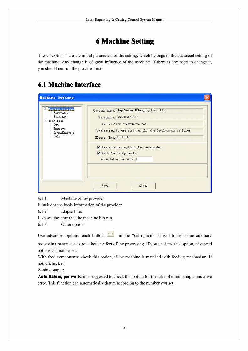
6666 MachineMachineMachineMachine SettingSettingSettingSetting
These “Options” are the initial parameters of the setting, which belongs to the advanced setting ofthe machine. Any change is of great influence of the machine. If there is any need to change it,you should consult the provider first.
6.16.16.16.1 MachineMachineMachineMachine InterfaceInterfaceInterfaceInterface
6.1.1 Machine of the providerIt includes the basic information of the provider.6.1.2 Elapse timeIt shows the time that the machine has run.6.1.3 Other options
Use advanced options: each button in the “set option” is used to set some auxiliary
processing parameter to get a better effect of the processing. If you uncheck this option, advancedoptions can not be set.With feed components: check this option, if the machine is matched with feeding mechanism. Ifnot, uncheck it.Zoning output:AutoAutoAutoAuto Datum,Datum,Datum,Datum, perperperper workworkworkwork: it is suggested to check this option for the sake of eliminating cumulativeerror. This function can automatically datum according to the number you set.
Laser Engraving & Cutting Control System Manual
41
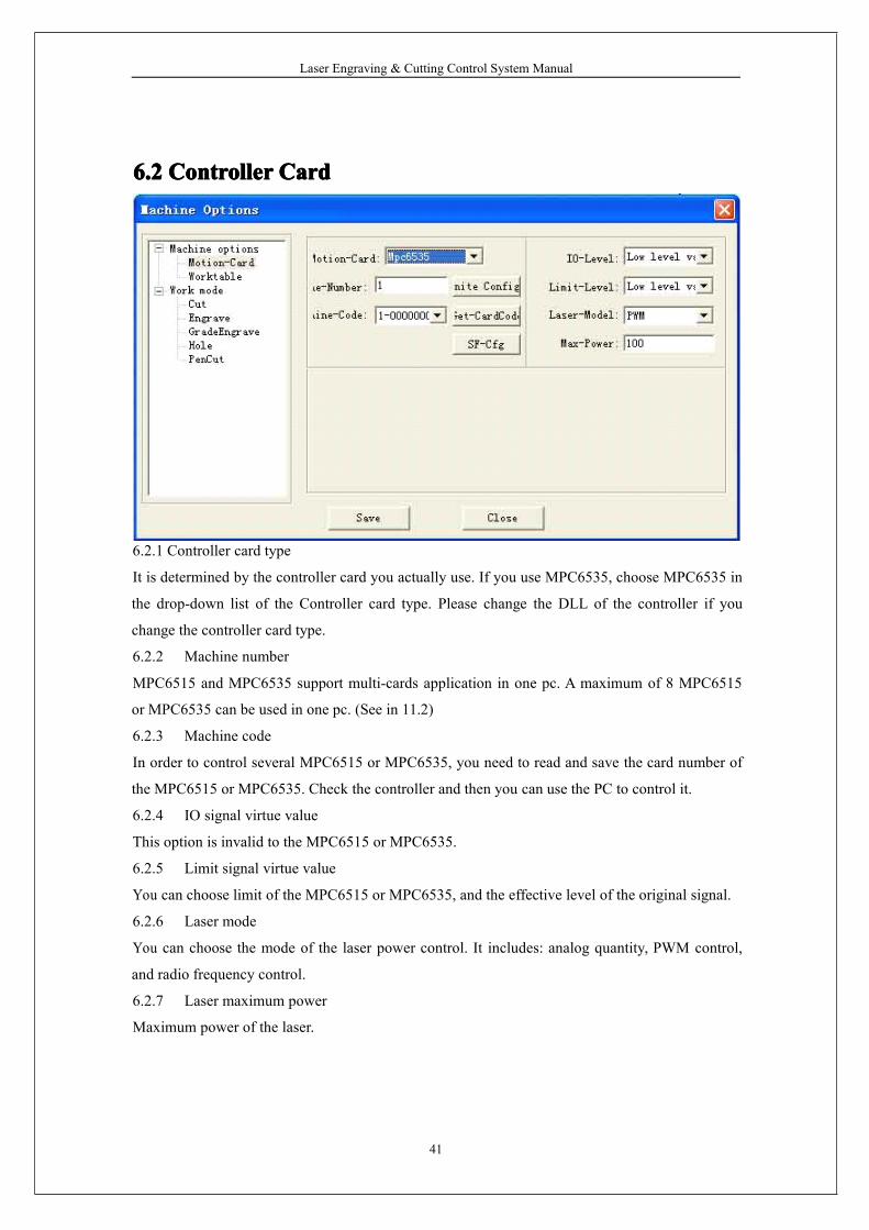
6.26.26.26.2 ControllerControllerControllerController CardCardCardCard
6.2.1 Controller card type
It is determined by the controller card you actually use. If you use MPC6535, choose MPC6535 in
the drop-down list of the Controller card type. Please change the DLL of the controller if you
change the controller card type.
6.2.2 Machine number
MPC6515 and MPC6535 support multi-cards application in one pc. A maximum of 8 MPC6515
or MPC6535 can be used in one pc. (See in 11.2)
6.2.3 Machine code
In order to control several MPC6515 or MPC6535, you need to read and save the card number of
the MPC6515 or MPC6535. Check the controller and then you can use the PC to control it.
6.2.4 IO signal virtue value
This option is invalid to the MPC6515 or MPC6535.
6.2.5 Limit signal virtue value
You can choose limit of the MPC6515 or MPC6535, and the effective level of the original signal.
6.2.6 Laser mode
You can choose the mode of the laser power control. It includes: analog quantity, PWM control,
and radio frequency control.
6.2.7 Laser maximum power
Maximum power of the laser.
Laser Engraving & Cutting Control System Manual
42
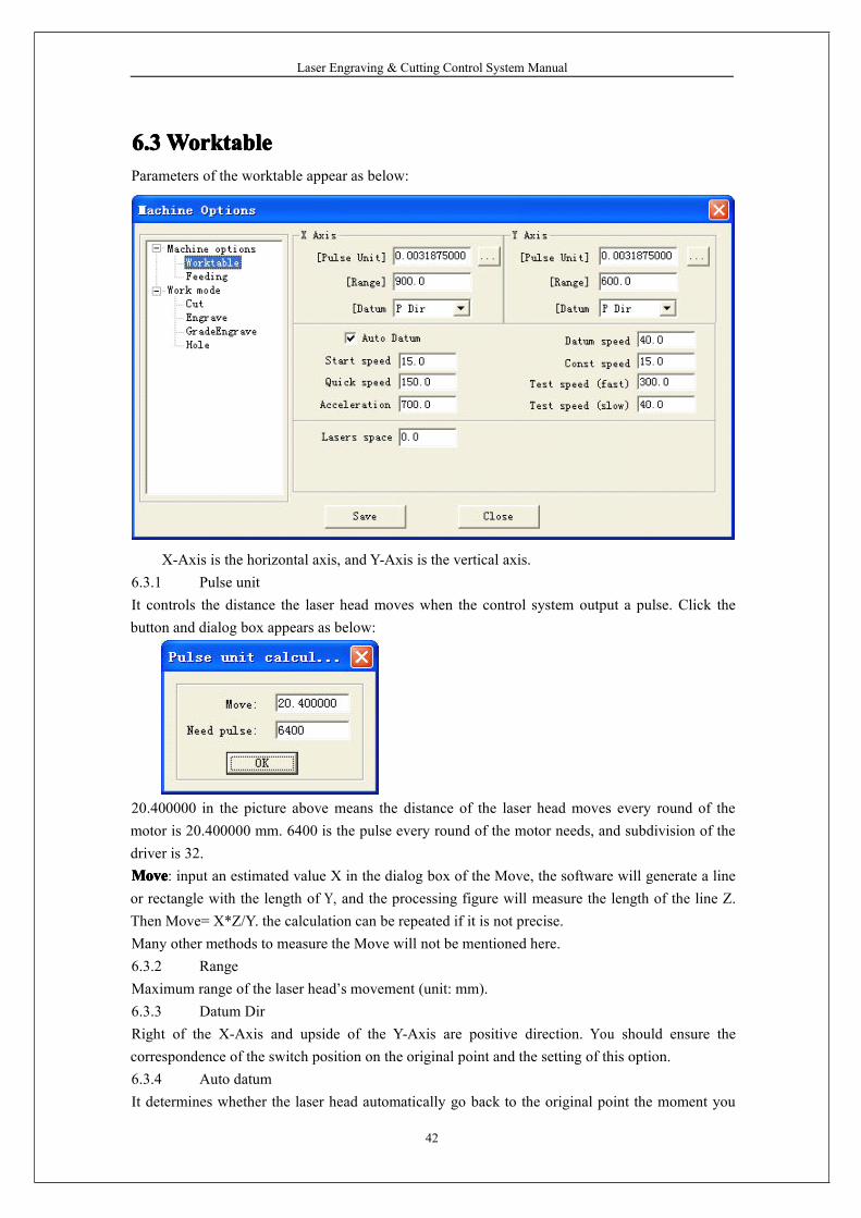
6.36.36.36.3WorktableWorktableWorktableWorktableParameters of the worktable appear as below:
X-Axis is the horizontal axis, and Y-Axis is the vertical axis.6.3.1 Pulse unitIt controls the distance the laser head moves when the control system output a pulse. Click thebutton and dialog box appears as below:
20.400000 in the picture above means the distance of the laser head moves every round of themotor is 20.400000 mm. 6400 is the pulse every round of the motor needs, and subdivision of thedriver is 32.MoveMoveMoveMove: input an estimated value X in the dialog box of the Move, the software will generate a lineor rectangle with the length of Y, and the processing figure will measure the length of the line Z.Then Move= X*Z/Y. the calculation can be repeated if it is not precise.Many other methods to measure the Move will not be mentioned here.6.3.2 RangeMaximum range of the laser head’s movement (unit: mm).6.3.3 Datum DirRight of the X-Axis and upside of the Y-Axis are positive direction. You should ensure thecorrespondence of the switch position on the original point and the setting of this option.6.3.4 Auto datumIt determines whether the laser head automatically go back to the original point the moment you
Laser Engraving & Cutting Control System Manual
43
run the software. If you uncheck it, speed of the laser head is relatively slow when you press thedirection button to avoid striking the machine. If you check it, speed will be quicker and no worryabout striking of the machine.6.3.5 Datum speedSpeed of the laser head going back to the original point. It should not be too large, or the switch ofthe original point may be damaged.6.3.6 Start speedStart speed of the two axes. A large value will shake intensively.6.3.7 Const speedIt is the maximum of the constant speed (cutting). It is constant motion if the (processing) speed islower than this speed; otherwise, it is variable motion.6.3.8 Quick speedIt is the highest speed of the laser head in the process when the laser is off.6.3.9 AccelerationIt is the acceleration of the movement on the X, Y-Axis. Acceleration in the engraving can be setin the “Laser engrave”.6.3.10 Quick acceleration6535 apply “S” type acceleration or deceleration to make the change of the speed smoother. Itmeans the acceleration of the acceleration change in the process. It is usually 10 times of theacceleration or more.6.3.11 Test speed (fast)Test speed of the laser head, when “Auto datum” is checked.6.3.12 Test speed (slow)Test speed of the laser head, when “Auto datum” is unchecked.6.3.13 Maximum jump speed of X-AxisIt is only suitable for MPC6535.It is the maximum of changing direction smoothly of the X-Axis. The smaller the parameter is, thebetter the quality is, but the lower efficiency of the processing is.6.3.14 Maximum jump speed of Y-AxisIt is only suitable for MPC6535.It is the maximum of changing direction smoothly of the Y-Axis. The smaller the parameter is, thebetter the quality is, but the lower efficiency of the processing is.
Laser Engraving & Cutting Control System Manual
44
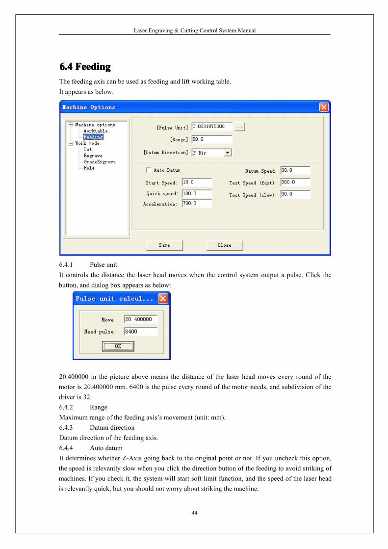
6.46.46.46.4 FeedingFeedingFeedingFeedingThe feeding axis can be used as feeding and lift working table.It appears as below:
6.4.1 Pulse unitIt controls the distance the laser head moves when the control system output a pulse. Click thebutton, and dialog box appears as below:
20.400000 in the picture above means the distance of the laser head moves every round of themotor is 20.400000 mm. 6400 is the pulse every round of the motor needs, and subdivision of thedriver is 32.6.4.2 RangeMaximum range of the feeding axis’s movement (unit: mm).6.4.3 Datum directionDatum direction of the feeding axis.6.4.4 Auto datumIt determines whether Z-Axis going back to the original point or not. If you uncheck this option,the speed is relevantly slow when you click the direction button of the feeding to avoid striking ofmachines. If you check it, the system will start soft limit function, and the speed of the laser headis relevantly quick, but you should not worry about striking the machine.
Laser Engraving & Cutting Control System Manual
45
6.4.5 Datum speedSpeed of the going back to the original point. It should not be too large, or the switch of theoriginal point may be damaged.6.4.6 Start speedStart speed of the feeding axes. A large value will shake intensively.6.4.7 Quick speedInvalid。6.4.8 AccelerationIt is the acceleration of the movement of the feeding axis.6.4.9 Test speed (fast)Test speed of the feeding speed, when “Auto datum” is checked.6.4.10 Test speed (slow)Test speed of the feeding speed, when “Auto datum” is unchecked.6.4.11 Datum distanceDistance Z-Axis goes when it goes back to the original point.
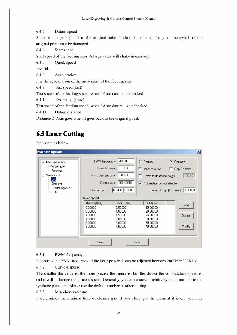
6.56.56.56.5 LaserLaserLaserLaser CuttingCuttingCuttingCuttingIt appears as below:
6.5.1 PWM frequencyIt controls the PWM frequency of the laser power. It can be adjusted between 200Hz-200KHz.6.5.2 Curve disperseThe smaller the value is, the more precise the figure is, but the slower the computation speed is,and it will influence the process speed. Generally, you can choose a relatively small number to cutsynthetic glass, and please use the default number in other cutting.6.5.3 Min close-gas timeIt determines the minimal time of closing gas. If you close gas the moment it is on, you may
Laser Engraving & Cutting Control System Manual
46
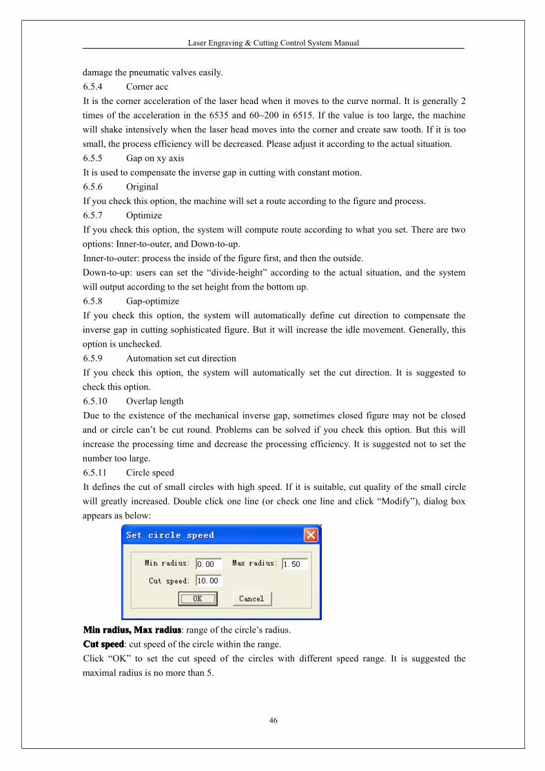
damage the pneumatic valves easily.6.5.4 Corner accIt is the corner acceleration of the laser head when it moves to the curve normal. It is generally 2times of the acceleration in the 6535 and 60~200 in 6515. If the value is too large, the machinewill shake intensively when the laser head moves into the corner and create saw tooth. If it is toosmall, the process efficiency will be decreased. Please adjust it according to the actual situation.6.5.5 Gap on xy axisIt is used to compensate the inverse gap in cutting with constant motion.6.5.6 OriginalIf you check this option, the machine will set a route according to the figure and process.6.5.7 OptimizeIf you check this option, the system will compute route according to what you set. There are twooptions: Inner-to-outer, and Down-to-up.Inner-to-outer: process the inside of the figure first, and then the outside.Down-to-up: users can set the “divide-height” according to the actual situation, and the systemwill output according to the set height from the bottom up.6.5.8 Gap-optimizeIf you check this option, the system will automatically define cut direction to compensate theinverse gap in cutting sophisticated figure. But it will increase the idle movement. Generally, thisoption is unchecked.6.5.9 Automation set cut directionIf you check this option, the system will automatically set the cut direction. It is suggested tocheck this option.6.5.10 Overlap lengthDue to the existence of the mechanical inverse gap, sometimes closed figure may not be closedand or circle can’t be cut round. Problems can be solved if you check this option. But this willincrease the processing time and decrease the processing efficiency. It is suggested not to set thenumber too large.6.5.11 Circle speedIt defines the cut of small circles with high speed. If it is suitable, cut quality of the small circlewill greatly increased. Double click one line (or check one line and click “Modify”), dialog boxappears as below:
MinMinMinMin radius,radius,radius,radius, MaxMaxMaxMax radiusradiusradiusradius: range of the circle’s radius.CutCutCutCut speedspeedspeedspeed: cut speed of the circle within the range.Click “OK” to set the cut speed of the circles with different speed range. It is suggested themaximal radius is no more than 5.
Laser Engraving & Cutting Control System Manual
47
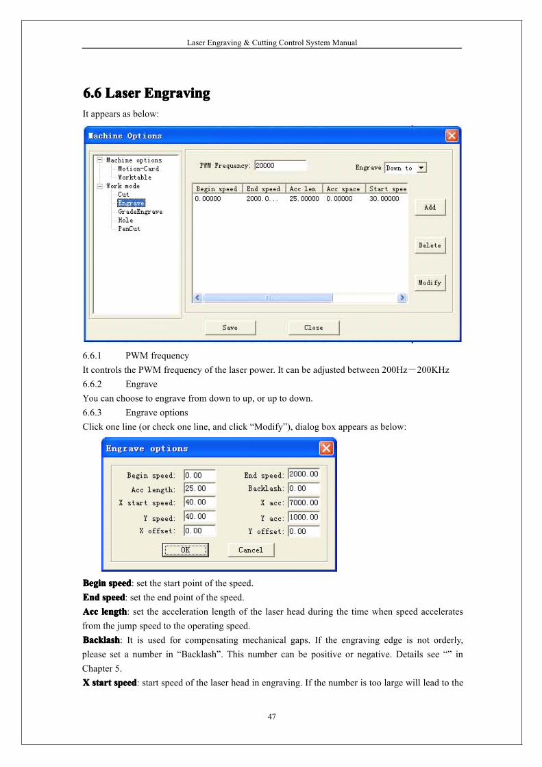
6.66.66.66.6 LaserLaserLaserLaser EngravingEngravingEngravingEngravingIt appears as below:
6.6.1 PWM frequencyIt controls the PWM frequency of the laser power. It can be adjusted between 200Hz-200KHz6.6.2 EngraveYou can choose to engrave from down to up, or up to down.6.6.3 Engrave optionsClick one line (or check one line, and click “Modify”), dialog box appears as below:
BeginBeginBeginBegin speedspeedspeedspeed: set the start point of the speed.EndEndEndEnd speedspeedspeedspeed: set the end point of the speed.AccAccAccAcc lengthlengthlengthlength: set the acceleration length of the laser head during the time when speed acceleratesfrom the jump speed to the operating speed.BacklashBacklashBacklashBacklash: It is used for compensating mechanical gaps. If the engraving edge is not orderly,please set a number in “Backlash”. This number can be positive or negative. Details see “” inChapter 5.XXXX startstartstartstart speedspeedspeedspeed: start speed of the laser head in engraving. If the number is too large will lead to the
Laser Engraving & Cutting Control System Manual
48
malposition of the engraving and greatly decrease the process efficiency.XXXX accaccaccacc: It is the acceleration of the X-axis from start speed to operating speed.YYYY speedspeedspeedspeed: It is the maximum of the laser head speed on the Y-axis. If the number is too large, themachine will shake intensively.YYYY accaccaccacc: It is the acceleration of the Y-axis from start speed to operating speed.XXXX offsetoffsetoffsetoffset: It is applied only to servo motor. When servo motor is chosen, offset will be generatedbetween the engraving and cutting position. It is to compensate offset on the X-axis in engraving.YYYY offsetoffsetoffsetoffset: It is applied only to servo motor. When servo motor is chosen, offset will be generatedbetween the engraving and cutting position. It is to compensate offset on the Y-axis in engraving.Click “OK” to set different process parameter according to different speed range.
6.76.76.76.7 GradeGradeGradeGrade EngravingEngravingEngravingEngravingSame as 6.5 “Laser Engraving”
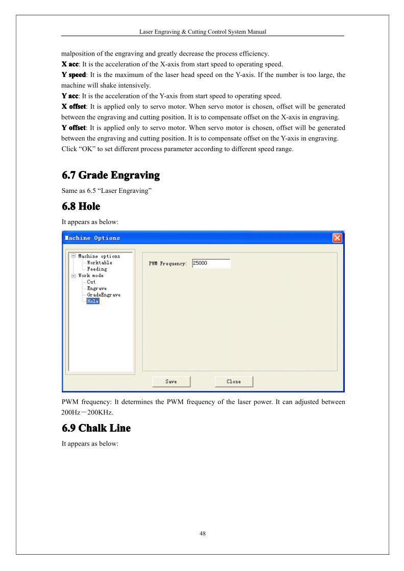
6.86.86.86.8 HoleHoleHoleHoleIt appears as below:
PWM frequency: It determines the PWM frequency of the laser power. It can adjusted between200Hz-200KHz.
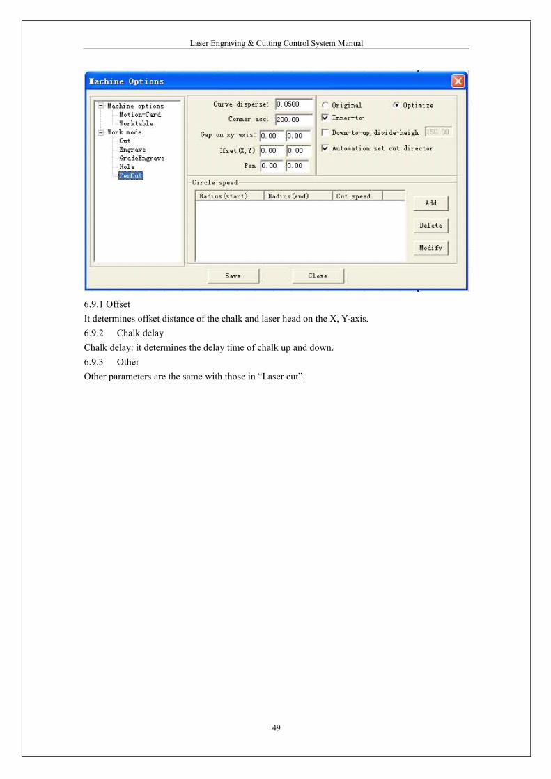
6.96.96.96.9 ChalkChalkChalkChalk LineLineLineLineIt appears as below:
Laser Engraving & Cutting Control System Manual
49
6.9.1 OffsetIt determines offset distance of the chalk and laser head on the X, Y-axis.6.9.2 Chalk delayChalk delay: it determines the delay time of chalk up and down.6.9.3 OtherOther parameters are the same with those in “Laser cut”.
Laser Engraving & Cutting Control System Manual
50
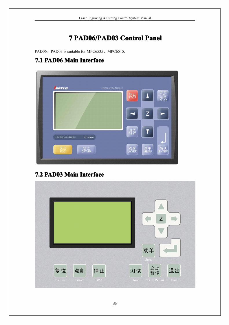
7777 PAD06/PAD03PAD06/PAD03PAD06/PAD03PAD06/PAD03 ControlControlControlControl PanelPanelPanelPanel
PAD06、PAD03 is suitable for MPC6535、MPC6515.
7.17.17.17.1 PAD06PAD06PAD06PAD06MainMainMainMain InterfaceInterfaceInterfaceInterface
7.27.27.27.2 PAD03PAD03PAD03PAD03MainMainMainMain InterfaceInterfaceInterfaceInterface
Laser Engraving & Cutting Control System Manual
51
DatumDatumDatumDatum: laser head move the original point of the machine slowly. It is mainly used to estimatecumulative error. You should make sure the application of datum switch and lead the switch signalto the controller.LaserLaserLaserLaser: Laser on/off.StopStopStopStop: Stop operation.TestTestTestTest: The laser head will run along the outline border of the processing data.Start/PauseStart/PauseStart/PauseStart/Pause: Start/pause the processing operation.EscEscEscEsc: Escape the current status window.MenuMenuMenuMenu: Enter accessory interface.
: Click this button, and then click and to move the Z axis. This function needs
hardware support.
: Enter.
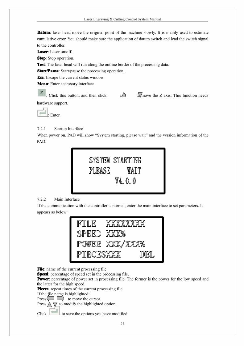
7.2.1 Startup InterfaceWhen power on, PAD will show “System starting, please wait” and the version information of thePAD.
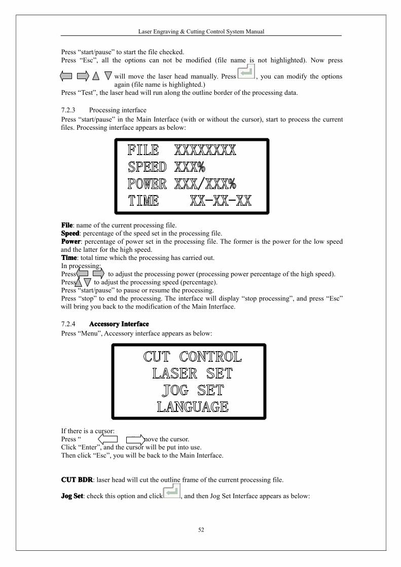
7.2.2 Main InterfaceIf the communication with the controller is normal, enter the main interface to set parameters. Itappears as below:
FileFileFileFile: name of the current processing fileSpeedSpeedSpeedSpeed: percentage of speed set in the processing file.PowerPowerPowerPower: percentage of power set in processing file. The former is the power for the low speed andthe latter for the high speed.PiecesPiecesPiecesPieces: repeat times of the current processing file.If the file name is highlighted:Press to move the cursor.Press to modify the highlighted option.
Click to save the options you have modified.
Laser Engraving & Cutting Control System Manual
52
Press “start/pause” to start the file checked.Press “Esc”, all the options can not be modified (file name is not highlighted). Now press
will move the laser head manually. Press , you can modify the optionsagain (file name is highlighted.)
Press “Test”, the laser head will run along the outline border of the processing data.
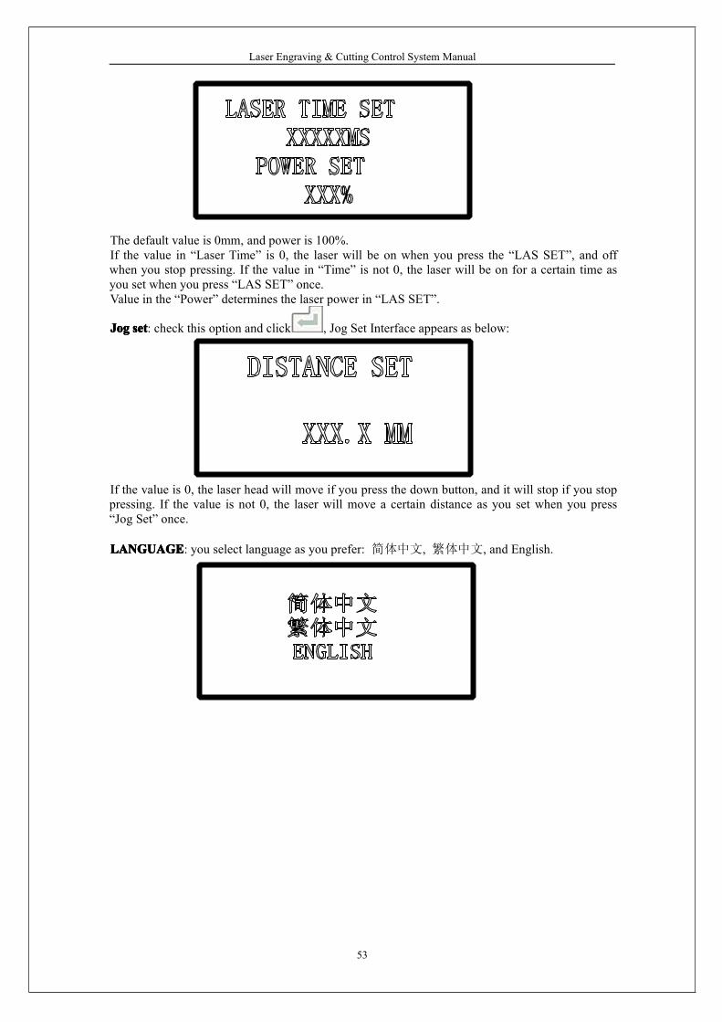
7.2.3 Processing interfacePress “start/pause” in the Main Interface (with or without the cursor), start to process the currentfiles. Processing interface appears as below:
FileFileFileFile: name of the current processing file.SpeedSpeedSpeedSpeed: percentage of the speed set in the processing file.PowerPowerPowerPower: percentage of power set in the processing file. The former is the power for the low speedand the latter for the high speed.TimeTimeTimeTime: total time which the processing has carried out.In processing:Press to adjust the processing power (processing power percentage of the high speed).Press to adjust the processing speed (percentage).Press “start/pause” to pause or resume the processing.Press “stop” to end the processing. The interface will display “stop processing”, and press “Esc”will bring you back to the modification of the Main Interface.
7.2.4 AccessoryAccessoryAccessoryAccessory InterfaceInterfaceInterfaceInterfacePress “Menu”, Accessory interface appears as below:
If there is a cursor:Press “ ”,“ ”to move the cursor.Click “Enter”, and the cursor will be put into use.Then click “Esc”, you will be back to the Main Interface.
CUTCUTCUTCUT BDRBDRBDRBDR: laser head will cut the outline frame of the current processing file.
JogJogJogJog SetSetSetSet: check this option and click , and then Jog Set Interface appears as below:
Laser Engraving & Cutting Control System Manual
53
The default value is 0mm, and power is 100%.If the value in “Laser Time” is 0, the laser will be on when you press the “LAS SET”, and offwhen you stop pressing. If the value in “Time” is not 0, the laser will be on for a certain time asyou set when you press “LAS SET” once.Value in the “Power” determines the laser power in “LAS SET”.
JogJogJogJog setsetsetset: check this option and click , Jog Set Interface appears as below:
If the value is 0, the laser head will move if you press the down button, and it will stop if you stoppressing. If the value is not 0, the laser will move a certain distance as you set when you press“Jog Set” once.
LANGUAGELANGUAGELANGUAGELANGUAGE: you select language as you prefer: 简体中文, 繁体中文, and English.
Laser Engraving & Cutting Control System Manual
54
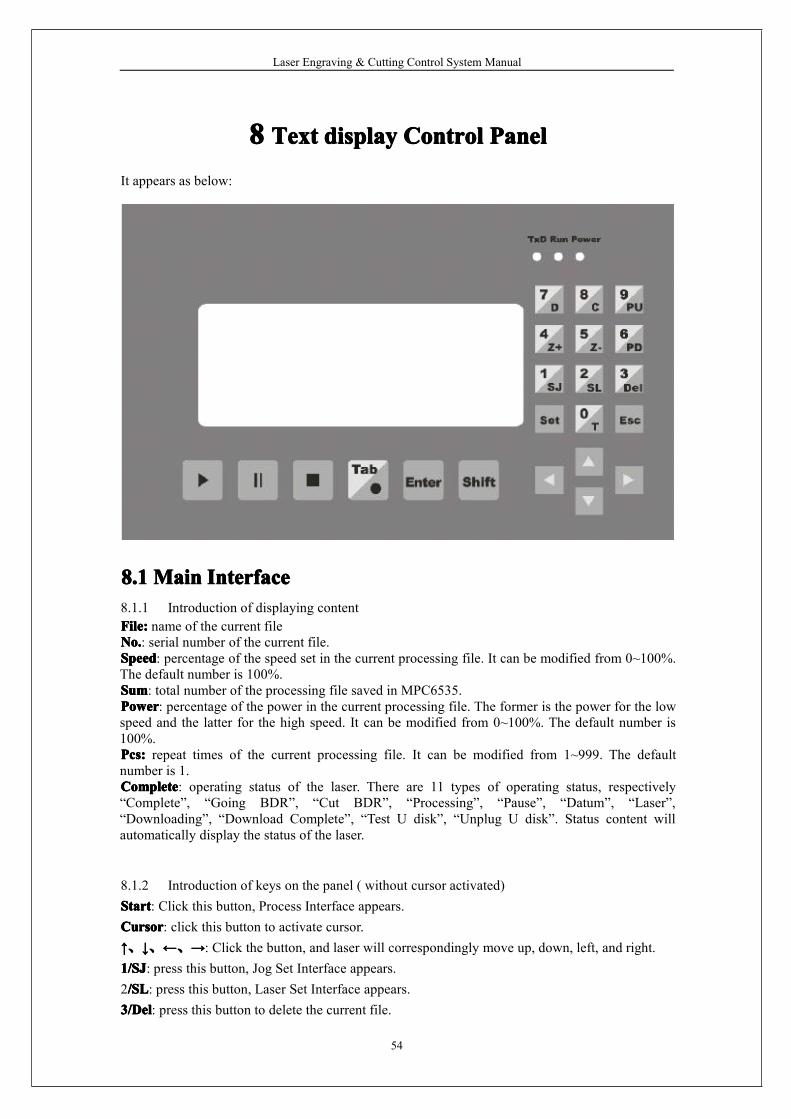
8888 TextTextTextText displaydisplaydisplaydisplay ControlControlControlControl PanelPanelPanelPanel
It appears as below:
8.18.18.18.1 MainMainMainMain InterfaceInterfaceInterfaceInterface8.1.1 Introduction of displaying contentFile:File:File:File: name of the current fileNo.No.No.No.: serial number of the current file.SpeedSpeedSpeedSpeed: percentage of the speed set in the current processing file. It can be modified from 0~100%.The default number is 100%.SumSumSumSum: total number of the processing file saved in MPC6535.PowerPowerPowerPower: percentage of the power in the current processing file. The former is the power for the lowspeed and the latter for the high speed. It can be modified from 0~100%. The default number is100%.Pcs:Pcs:Pcs:Pcs: repeat times of the current processing file. It can be modified from 1~999. The defaultnumber is 1.CompleteCompleteCompleteComplete: operating status of the laser. There are 11 types of operating status, respectively“Complete”, “Going BDR”, “Cut BDR”, “Processing”, “Pause”, “Datum”, “Laser”,“Downloading”, “Download Complete”, “Test U disk”, “Unplug U disk”. Status content willautomatically display the status of the laser.
8.1.2 Introduction of keys on the panel ( without cursor activated)StartStartStartStart: Click this button, Process Interface appears.CursorCursorCursorCursor: click this button to activate cursor.↑↑↑↑、↓↓↓↓、←←←←、→→→→: Click the button, and laser will correspondingly move up, down, left, and right.1/SJ1/SJ1/SJ1/SJ: press this button, Jog Set Interface appears.2/SL/SL/SL/SL: press this button, Laser Set Interface appears.3/Del3/Del3/Del3/Del: press this button to delete the current file.

Laser Engraving & Cutting Control System Manual
55
4/Z+4/Z+4/Z+4/Z+: press this button, laser head will move toward the positive direction of the Z-axis.5/Z-5/Z-5/Z-5/Z-: press this button, laser head will move toward the negtive direction of the Z-axis.6/PD6/PD6/PD6/PD: press this button, the next file with the serial number lessen 1 appears.7/D7/D7/D7/D: press this button, the laser head will datum.8/C8/C8/C8/C: press this button, and then the laser will cut the border line with 100% power.9/PU9/PU9/PU9/PU: press this button, the last file with the serial number added 1 appears.The other keys are invalid.
8.1.3 Introduction of keys on the panel (with cursor activated)CursorCursorCursorCursor: press “Cursor” again, and the cursor will move to the next modifiable parameter, that is,Speed-Power (slow)-Power (quick)-Sum. Press “Cursor” when the cursor is in “Sum”, it willdisappear. Every parameter with the cursor activated can be modified by the number key on theright of the control panel. Click “Enter” after modification.EnterEnterEnterEnter: click this button to confirm the parameter you have modified.EscEscEscEsc: click this button to clear the parameter to be modified.The other keys are invalid.All the parameter set can be saved when power down.
8.28.28.28.2 JogJogJogJog SetSetSetSet InterfaceInterfaceInterfaceInterfacePress “1/SJ” in the Jog Set Interface, you can input Jog distance from the number keys, and press“Enter” to save it. The default number is 0mm. In this case, laser head will move when you press“1/SJ”, and will stop when you stop pressing. If the set number is 100mm, laser head willautomatically stop after moving for 100mm once you press the button.Press “Esc” to go back to the Main Interface. The other keys are invalid.This parameter mainly to define the jog distance on the four directions: up, down, right, and left.The precision of this parameter is 0.1mm. It can be saved when power down.
8.38.38.38.3 LaserLaserLaserLaser SetSetSetSet InterfaceInterfaceInterfaceInterfaceWhen the cursor is not activated, press “2/SL” in the Main Interface, Laser Set Interface appears,and you can set the Time and Power of the Laser.After Laser Set Interface appears, you can press “Cursor” to activate Cursor, you can input “Time”and “Power” from the number keys, and then press “Enter” to save it. The default “Time” is 0ms,and default “Power” is 100 % (range of the “Power” is 0~100%, and range of “Time” is0~99999ms).If you input 0 in “Time”, the laser will be on when you press this button, and off when you stoppressing. If you set other number, say, 200ms, the laser will be on for 200ms after you press thisbutton.Click “Esc”, you will be back to the Main Interface. The other keys are invalid.
8.48.48.48.4 ProcessingProcessingProcessingProcessing InterfaceInterfaceInterfaceInterfaceWhen the cursor is not activated, press “Start”, Processing Interface will appear. Content of theText Display are as below:FileFileFileFile: display the name of the processing file.SpeedSpeedSpeedSpeed: display the speed of the processing (speed set in the Main Interface). You can adjust it up
Laser Engraving & Cutting Control System Manual
56
or down (one step) by the ↑, ↓ in processing. The adjust range is 0~100%.PowerPowerPowerPower: display the power of the processing (power set in Main Interface). You can adjust thepower for the high speed up or down by the ←, → in processing (you can not adjust the power forthe low speed, but you can only set it in the Main Interface). The adjust range is 0~100%.TimeTimeTimeTime: display the total for processing.StatusStatusStatusStatus: display the movement status of the laser.
In Processing Interface, functions of the keys on the panel are:EscEscEscEsc: click this button, and you will be back to the Main Interface.0/T0/T0/T0/T: click this button, and then the laser will scan the border line.····/L/L/L/L: click this button, the laser will be on (“Time” and “Power” can be set in the Laser SetInterface).StartStartStartStart: press this button to start processing. After it starts, this button functions as“Pause/Resume”.Pause/ResumePause/ResumePause/ResumePause/Resume: press this button to pause the processing. Another press will resume theprocessing.StopStopStopStop: press this button to stop processing and the laser head goes back the starting point of theprocessing.NoteNoteNoteNote: “Stop” button is the instant stop direction to the system. It will greatly strike the machinewhen you press it as the machine is running with a high speed. On the contrary, “Pause/Resume”is the slow stop direction to the system. Therefore, if you want to stop processing when themachine is running, first press “Pause/Resume” to pause and then “Stop” to stop processing.
Laser Engraving & Cutting Control System Manual
57
9999 ErrorErrorErrorError AlarmAlarmAlarmAlarm InterfaceInterfaceInterfaceInterface
9.19.19.19.1 ErrorErrorErrorErrorAlarmAlarmAlarmAlarm InterfaceInterfaceInterfaceInterfaceBriefPAD03 (PAD06) Operating Panel will offer real-time display of the Error Alarm of the Controlresulted by any improper operation or external signal interruption. If will help the users to identifythe reason of the error and correct the operation or eliminate the interruption.
9.29.29.29.2 SoftSoftSoftSoft LimitLimitLimitLimit StopStopStopStop
ReasonReasonReasonReason: figure to process is beyond the range of the worktable. Usually it happens when the laserhead datum and there is no correct docking point for the laser head in the case of immediateoutput.SolutionSolutionSolutionSolution: move the laser head to make the figure inside the range of the worktable. You can alsouncheck the “√” of the immediate output and download the processing data again.
9.39.39.39.3 HardHardHardHard LimitLimitLimitLimit StopStopStopStop
ReasonReasonReasonReason: user checks the immediate output when the laser head doesn’t datum, and then theprocessing range is beyond the worktable and stop when it gets limit signal. It will also happenwhen there are interruption signal due to the sophisticated surrounding.SolutionSolutionSolutionSolution: move the laser head to make the figure inside the range of the worktable. If it happensduring the processing and doesn’t touch the switch, the reason is the interruption, please check theground wire.
9.49.49.49.4 StorageStorageStorageStorage OverloadOverloadOverloadOverloadAlarmAlarmAlarmAlarm
Laser Engraving & Cutting Control System Manual
58
ReasonReasonReasonReason:1. Total number of the download files is over 32 which are the maximum of the storage.2. The download file is larger than the storage capacity.SolutionSolutionSolutionSolution: make sure the download file is not larger than the total storage capacity. Delete uselessprocessing files to release storage space.
9.59.59.59.5 ConfigConfigConfigConfig NotNotNotNot MatchMatchMatchMatch FirmwareFirmwareFirmwareFirmware
ReasonReasonReasonReason: you didn’t download the configuration file with the firmware you have updated.SolutionSolutionSolutionSolution:1. Open the install catalog of the application, run the version check program to check if theversion of the DLL matches the firmware or not. If not, contact the provider to get the matchedDLL.2. Double click the application to download configuration.
9.69.69.69.6 DLLDLLDLLDLLNotNotNotNot MatchMatchMatchMatch FirmwareFirmwareFirmwareFirmware
ReasonReasonReasonReason: the DLL used to generate the processing file dose not match the firmware.SolutionSolutionSolutionSolution: see 10.1
9.79.79.79.7 HardwareHardwareHardwareHardware NotNotNotNot MatchMatchMatchMatch FirmwareFirmwareFirmwareFirmware
Laser Engraving & Cutting Control System Manual
59
ReasonReasonReasonReason: hardware does not support the firmware you have undated.SolutionSolutionSolutionSolution:Steps: 1. copy the new firmware file (XXXX.FWM and XXXX.HDW) to the root directory of theU disk (FAT16 after formatting, it is suggested there are no other file in the U disk).2. When the power of the MPC6515/35 is down, plug the U disk and then resume the powerprovision. The indicator light on the MPC6515/35 main board will keep on after flashes twice(2~5 seconds, depends on the size of the firmware), and the firmware is updating. If there is noindicator light, judge the process by the introduction of the U disk. 6536 can be judged by theindicator light.3. D1 on the MPC6515 flashing quickly indicates the complete of the updating of the firmware; ifthere is indicator light, judge the procedure by it. The procedure will take about 15 seconds.4. Unplug U disk, MPC6515/35 will start the DSP firmware program normally.If MPC6515/35 does not work after you unplug U disk, there may be error in the updating of thefirmware. You can repeat the above steps. If MPC6515/35 still does not work, contact theprovider.
Laser Engraving & Cutting Control System Manual
60
10101010 ToolToolToolTool SoftwareSoftwareSoftwareSoftware
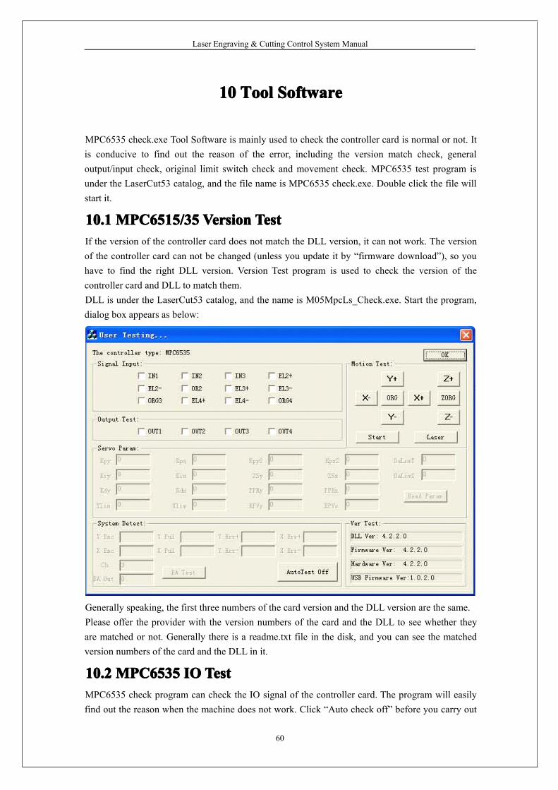
MPC6535 check.exe Tool Software is mainly used to check the controller card is normal or not. Itis conducive to find out the reason of the error, including the version match check, generaloutput/input check, original limit switch check and movement check. MPC6535 test program isunder the LaserCut53 catalog, and the file name is MPC6535 check.exe. Double click the file willstart it.
10.110.110.110.1 MPC6515/35MPC6515/35MPC6515/35MPC6515/35 VersionVersionVersionVersion TestTestTestTestIf the version of the controller card does not match the DLL version, it can not work. The versionof the controller card can not be changed (unless you update it by “firmware download”), so youhave to find the right DLL version. Version Test program is used to check the version of thecontroller card and DLL to match them.DLL is under the LaserCut53 catalog, and the name is M05MpcLs_Check.exe. Start the program,dialog box appears as below:
Generally speaking, the first three numbers of the card version and the DLL version are the same.Please offer the provider with the version numbers of the card and the DLL to see whether theyare matched or not. Generally there is a readme.txt file in the disk, and you can see the matchedversion numbers of the card and the DLL in it.
10.210.210.210.2 MPC6535MPC6535MPC6535MPC6535 IOIOIOIO TestTestTestTestMPC6535 check program can check the IO signal of the controller card. The program will easilyfind out the reason when the machine does not work. Click “Auto check off” before you carry out
Laser Engraving & Cutting Control System Manual
61
the IO test, and the program will display “Auto check on”.
10.2.1 General Input SignalDefinitions of the connectors between the input signal and external buttons are:
Signal 1 2 3Input IN1 IN2 IN3Function Foot switch Uncapping
protectionWaterprotection
Press one external button to check the corresponding signal react or not. means there are inputof signals.
10.2.2 General Output SignalCheck one signal and click it to see whether the external equipment reacts or not. means thereare output of signals. Definitions of connectors between the output signal and external buttons are:
Signal 1 2 3 4Output OUT1 OUT2 OUT3 OUT4Function Blow ctrlol Work finished
denoteU-Disk denote Reserved
10.2.3 Limit Datum SignalDatum Signal: means there are input signals. If the laser head is away from the datum switch,and there are input signal, there may be damage to the datum switch or error of the lines.Limit Signal: means there are input signals. If there is such signal input, the laser head can notmove (toward one direction). If the laser head is away from the limit switch, and there is signalinput, there may be damage to the limit switch or error of the lines.10.2.4 Movement TestIt can check whether each movement axis works well or not. Off-line laser movement test isdetermined by the download configuration of the software.
Laser Engraving & Cutting Control System Manual
62
11111111 AppendixAppendixAppendixAppendix
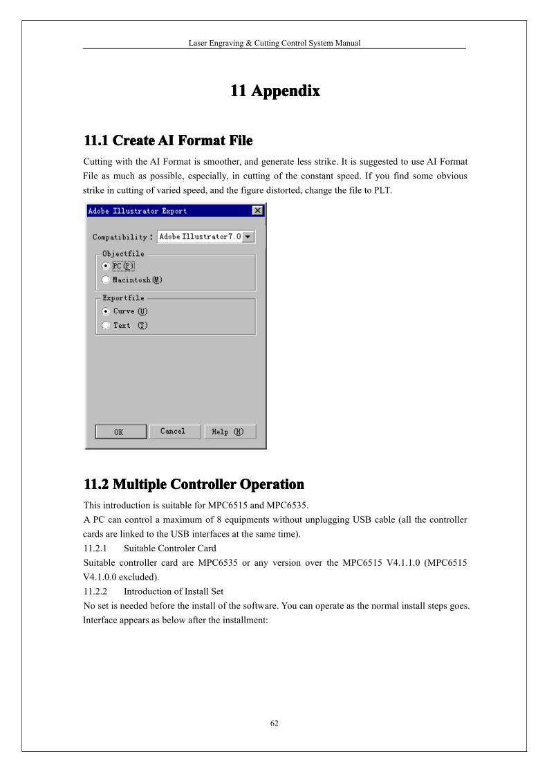
11.111.111.111.1 CreateCreateCreateCreateAIAIAIAI FormatFormatFormatFormat FileFileFileFileCutting with the AI Format is smoother, and generate less strike. It is suggested to use AI FormatFile as much as possible, especially, in cutting of the constant speed. If you find some obviousstrike in cutting of varied speed, and the figure distorted, change the file to PLT.
11.211.211.211.2 MultipleMultipleMultipleMultiple ControllerControllerControllerController OperationOperationOperationOperationThis introduction is suitable for MPC6515 and MPC6535.A PC can control a maximum of 8 equipments without unplugging USB cable (all the controllercards are linked to the USB interfaces at the same time).11.2.1 Suitable Controler CardSuitable controller card are MPC6535 or any version over the MPC6515 V4.1.1.0 (MPC6515V4.1.0.0 excluded).11.2.2 Introduction of Install SetNo set is needed before the install of the software. You can operate as the normal install steps goes.Interface appears as below after the installment:
Laser Engraving & Cutting Control System Manual
63
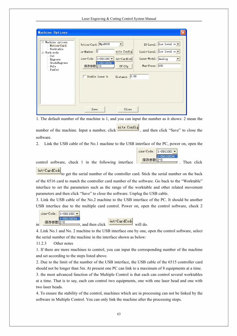
1. The default number of the machine is 1, and you can input the number as it shows: 2 mean the
number of the machine. Input a number, click , and then click “Save” to close the
software.2. Link the USB cable of the No.1 machine to the USB interface of the PC, power on, open the
control software, check 1 in the following interface . Then click
to get the serial number of the controller card. Stick the serial number on the back
of the 6516 card to match the controller card number of the software. Go back to the “Worktable”interface to set the parameters such as the range of the worktable and other related movementparameters and then click “Save” to close the software. Unplug the USB cable.3. Link the USB cable of the No.2 machine to the USB interface of the PC. It should be anotherUSB interface due to the multiple card control. Power on, open the control software, check 2
in , and then click will do.4. Link No.1 and No. 2 machine to the USB interface one by one, open the control software, selectthe serial number of the machine in the interface shown as below:11.2.3 Other notes1. If there are more machines to control, you can input the corresponding number of the machineand set according to the steps listed above.2. Due to the limit of the number of the USB interface, the USB cable of the 6515 controller cardshould not be longer than 5m. At present one PC can link to a maximum of 8 equipments at a time.3. the most advanced function of the Multiple Control is that each can control several worktablesat a time. That is to say, each can control two equipments, one with one laser head and one withtwo laser heads.4. To ensure the stability of the control, machines which are in processing can not be linked by thesoftware in Multiple Control. You can only link the machine after the processing stops.
Laser Engraving & Cutting Control System Manual
64
11.311.311.311.3 MPC6535MPC6535MPC6535MPC6535 PowerPowerPowerPower DownDownDownDownAutoAutoAutoAuto RecoveryRecoveryRecoveryRecovery FunctionFunctionFunctionFunctionThis function is the customized version. It is not added to the released version. You can contact theprovider to update the board and DLL if you want this version.MPC6535 firmware DSP version No.: V4.2.1.10
hardware FPGA version No.: V4.2.1.0Dll Dll version No.: V4.2.1.10PadFmw PAD Firmware version No.:V4.2.1
Usage: modify all the parameters in syscfg.ini.1. CanContinueForEngrave=1Introduction of parameter set:
When it is 1, power down memory is valid.When it is 0, power down memory is invalid.
Note: users should not easily change this parameter.2. SaveBreakTime=0.002 It means: the number multiplied by 1000 is the actual compensatingdistance.Introduction of the parameter set:
0.002 means: the number multiplied by 1000 is the actual compensating distance.Note: user can modify this number according to the actual situation (download new configurationfiles after modification).
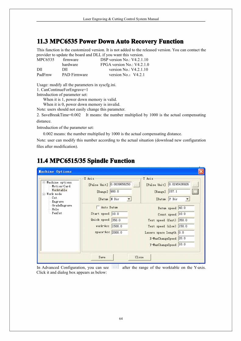
11.411.411.411.4 MPC6515/35MPC6515/35MPC6515/35MPC6515/35 SpindleSpindleSpindleSpindle FunctionFunctionFunctionFunction
In Advanced Configuration, you can see after the range of the worktable on the Y-axis.Click it and dialog box appears as below:
Laser Engraving & Cutting Control System Manual
65
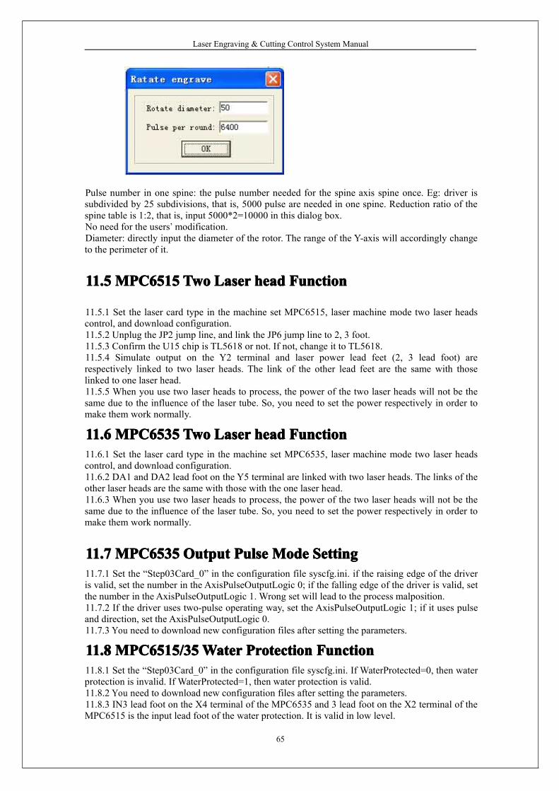
Pulse number in one spine: the pulse number needed for the spine axis spine once. Eg: driver issubdivided by 25 subdivisions, that is, 5000 pulse are needed in one spine. Reduction ratio of thespine table is 1:2, that is, input 5000*2=10000 in this dialog box.No need for the users’ modification.Diameter: directly input the diameter of the rotor. The range of the Y-axis will accordingly changeto the perimeter of it.
11.511.511.511.5 MPC6515MPC6515MPC6515MPC6515 TwoTwoTwoTwo LaserLaserLaserLaser headheadheadhead FunctionFunctionFunctionFunction
11.5.1 Set the laser card type in the machine set MPC6515, laser machine mode two laser headscontrol, and download configuration.11.5.2 Unplug the JP2 jump line, and link the JP6 jump line to 2, 3 foot.11.5.3 Confirm the U15 chip is TL5618 or not. If not, change it to TL5618.11.5.4 Simulate output on the Y2 terminal and laser power lead feet (2, 3 lead foot) arerespectively linked to two laser heads. The link of the other lead feet are the same with thoselinked to one laser head.11.5.5 When you use two laser heads to process, the power of the two laser heads will not be thesame due to the influence of the laser tube. So, you need to set the power respectively in order tomake them work normally.
11.611.611.611.6 MPC6535MPC6535MPC6535MPC6535 TwoTwoTwoTwo LaserLaserLaserLaser headheadheadhead FunctionFunctionFunctionFunction11.6.1 Set the laser card type in the machine set MPC6535, laser machine mode two laser headscontrol, and download configuration.11.6.2 DA1 and DA2 lead foot on the Y5 terminal are linked with two laser heads. The links of theother laser heads are the same with those with the one laser head.11.6.3 When you use two laser heads to process, the power of the two laser heads will not be thesame due to the influence of the laser tube. So, you need to set the power respectively in order tomake them work normally.
11.711.711.711.7 MPC6535MPC6535MPC6535MPC6535 OutputOutputOutputOutput PulsePulsePulsePulse ModeModeModeMode SettingSettingSettingSetting11.7.1 Set the “Step03Card_0” in the configuration file syscfg.ini. if the raising edge of the driveris valid, set the number in the AxisPulseOutputLogic 0; if the falling edge of the driver is valid, setthe number in the AxisPulseOutputLogic 1. Wrong set will lead to the process malposition.11.7.2 If the driver uses two-pulse operating way, set the AxisPulseOutputLogic 1; if it uses pulseand direction, set the AxisPulseOutputLogic 0.11.7.3 You need to download new configuration files after setting the parameters.
11.811.811.811.8 MPC6515/35MPC6515/35MPC6515/35MPC6515/35WaterWaterWaterWater ProtectionProtectionProtectionProtection FunctionFunctionFunctionFunction11.8.1 Set the “Step03Card_0” in the configuration file syscfg.ini. If WaterProtected=0, then waterprotection is invalid. If WaterProtected=1, then water protection is valid.11.8.2 You need to download new configuration files after setting the parameters.11.8.3 IN3 lead foot on the X4 terminal of the MPC6535 and 3 lead foot on the X2 terminal of theMPC6515 is the input lead foot of the water protection. It is valid in low level.
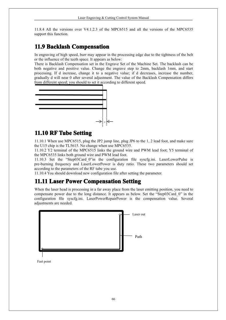
Laser Engraving & Cutting Control System Manual
66
11.8.4 All the versions over V4.1.2.3 of the MPC6515 and all the versions of the MPC6535support this function.
11.911.911.911.9 BacklashBacklashBacklashBacklash CompensationCompensationCompensationCompensationIn engraving of high speed, burr may appear in the processing edge due to the tightness of the beltor the influence of the teeth space. It appears as below:There is Backlash Compensation set in the Engrave Set of the Machine Set. The backlash can beboth negative and positive value. Change the engrave step to 2mm, backlash 1mm, and startprocessing. If d increase, change it to a negative value; if d decreases, increase the number,gradually d will near 0 after several adjustment. The value of the Backlash Compensation differsfrom different speed; you should to set it according to different speed.
d
11.1011.1011.1011.10 RFRFRFRFTubeTubeTubeTube SettingSettingSettingSetting11.10.1 When use MPC6515, plug the JP2 jump line, plug JP6 to the 1, 2 lead foot, and make surethe U15 chip is the TL5615. No change when use MPC6535.11.10.2 Y2 terminal of the MPC6515 links the ground wire and PWM lead foot; Y5 terminal ofthe MPC6535 links both ground wire and PWM lead foot.11.10.3 Set the “Step03Card_0”in the configuration file syscfg.ini. LaserLowerPulse ispre-burning frequency and LaserLowerPower is duty ratio. These two parameters should setaccording to the parameters of the RF tube you use.11.10.4 You should download new configuration file after setting the parameter.
11.1111.1111.1111.11 LaserLaserLaserLaser PowerPowerPowerPower CompensationCompensationCompensationCompensation SettingSettingSettingSettingWhen the laser head is processing in a far away place from the laser emitting position, you need tocompensate power due to the long distance. It appears as below. Set the “Step03Card_0” in theconfiguration file syscfg.ini. LaserPowerRepairPower is the compensation value. Severaladjustments are needed.
Laser out
Fast point
Path
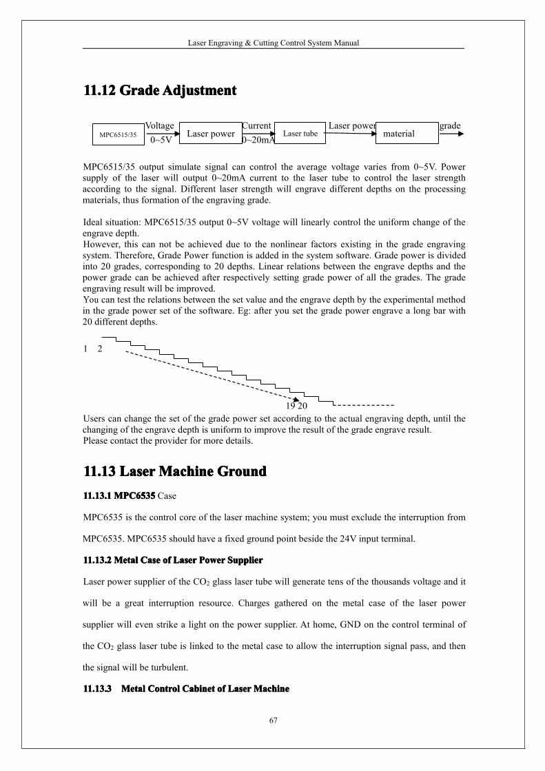
Laser Engraving & Cutting Control System Manual
67
11.1211.1211.1211.12 GradeGradeGradeGradeAdjustmentAdjustmentAdjustmentAdjustment
Voltage Current Laser power grade0~5V 0~20mA
MPC6515/35 output simulate signal can control the average voltage varies from 0~5V. Powersupply of the laser will output 0~20mA current to the laser tube to control the laser strengthaccording to the signal. Different laser strength will engrave different depths on the processingmaterials, thus formation of the engraving grade.
Ideal situation: MPC6515/35 output 0~5V voltage will linearly control the uniform change of theengrave depth.However, this can not be achieved due to the nonlinear factors existing in the grade engravingsystem. Therefore, Grade Power function is added in the system software. Grade power is dividedinto 20 grades, corresponding to 20 depths. Linear relations between the engrave depths and thepower grade can be achieved after respectively setting grade power of all the grades. The gradeengraving result will be improved.You can test the relations between the set value and the engrave depth by the experimental methodin the grade power set of the software. Eg: after you set the grade power engrave a long bar with20 different depths.
1 2
19 20Users can change the set of the grade power set according to the actual engraving depth, until thechanging of the engrave depth is uniform to improve the result of the grade engrave result.Please contact the provider for more details.
11.1311.1311.1311.13 LaserLaserLaserLaserMachineMachineMachineMachine GroundGroundGroundGround11.13.111.13.111.13.111.13.1 MPC6535MPC6535MPC6535MPC6535 Case
MPC6535 is the control core of the laser machine system; you must exclude the interruption from
MPC6535. MPC6535 should have a fixed ground point beside the 24V input terminal.
11.13.211.13.211.13.211.13.2 MetalMetalMetalMetal CaseCaseCaseCase ofofofof LaserLaserLaserLaser PowerPowerPowerPower SupplierSupplierSupplierSupplier
Laser power supplier of the CO2 glass laser tube will generate tens of the thousands voltage and it
will be a great interruption resource. Charges gathered on the metal case of the laser power
supplier will even strike a light on the power supplier. At home, GND on the control terminal of
the CO2 glass laser tube is linked to the metal case to allow the interruption signal pass, and then
the signal will be turbulent.
11.13.311.13.311.13.311.13.3 MetalMetalMetalMetal ControlControlControlControl CabinetCabinetCabinetCabinet ofofofof LaserLaserLaserLaserMachineMachineMachineMachine
MPC6515/35 materialLaser power Laser tube
Laser Engraving & Cutting Control System Manual
68
MPC6535, driver, switch power supply and even laser power supply are installed on the metal
control cabinet of the laser machine. In the case of laser radiation and external interruption, it will
be electrified and the people will feel numb when touch it and it may even sparks. Electrostatic
charge on the metal case will release to the controller through the cable and make the control
turbulent.
11.13.411.13.411.13.411.13.4 MetalMetalMetalMetal CaseCaseCaseCase ofofofof PCPCPCPC
Usually PE terminal of the Computer which are the power supply are not connected to the ground.No filtering function of the computer power supply will make the metal case electrified. Computeris linked to the USB cable of the laser controller and then GND of the laser power supply is linkedwith GND of the Computer.
11.1411.1411.1411.14 FQAFQAFQAFQA11.14.1 Superposition appears in grade engravingThis always occurs when the figure is very small and the set value in the “Grade width” is too big.Please input a smaller number in “Grade width”.11.14.2 Figure can only be moved toward one direction. Click “Shift” or “Ctrl” will do.11.14.3 PLT figure can’t be engravedReason: the figure is unclosed or overlapped. Please use the “data check” tool to check if there aresuch occasions.11.14.4 Size of the output of engrave/cut is not the same with the figure.Please adjust the “Pulse Unit”.11.14.5 When engraving, the edge is not in orderThis may happen when you use DSP5.3 engrave software. It is mainly caused by the backlash.You can adjust it as follow:1. Draw a rectangle, set the 0.5mm in “Laser Engrave” and “Engrave Step”.Theoretically, the engrave result will be ok, that is, edges of the odd lines are in order and edges ofthe even lines are in order. But some odd lines and even lines may also be in order.2. Open “Set Engrave Options”, you will see different processing parameters fordifferent speed. But set values in the “Backlash” are all 0. You can set the value according to theactual situation, both negative and positive.3. If you require a better engrave result, choose one direction laser on. Uncheckthe “Bi-Dir” will do. But this will decrease the process efficiency.11.14.6 X-axis or Y-axis doesn’t move (MPC6515)Set direct voltage 5V by a multimeter, test the voltage between 1 and 4 lead feet on the Y4 or Y5terminal (X Y-axis pulse direction output terminal). Take Y-axis as an example. Click up or downbutton, the normal value is about 2.8V. If it is not, control car is damaged. Please change controllercard. If it is, step on.Change the output terminals of the two drivers, and click up or down button. If X-axis is right,then Y-axis motor is damaged. Please change Y-axis motor. If X-axis does not move, then Y-axisdriver is damaged. Please change Y-axis driver.11.14.7 X-axis or Y-axis doesn’t move (MPC6535)Set direct voltage 5V by a multimeter, test the voltage between PULX (or PULY) and GND. Take
Laser Engraving & Cutting Control System Manual
69
Y-axis as an example. Click up or down button, the normal value is about 2.8V. If it is not,controller card is damaged. Please change controller card. If it is, step on.Change the output terminals of the two drivers, and click up or down button. If X-axis is right,then Y-axis motor is damaged. Please change Y-axis motor. If X-axis does not move, then Y-axisdriver is damaged. Please change Y-axis driver.11.14.8 X-axis or Y-axis can only move to one direction (MPC6515)Set direct voltage 5V by a multimeter, test the voltage between 2 and 4 lead feet on the Y4 or Y5terminal (X Y-axis pulse direction output terminal). Take X-axis as an example. Click “left” andthen “right” button to see if there are changes of the voltage (higher than 2.8V or lower than 0.8V).If not, the controller card is damaged. Please change it. If yes, check if the driver is ok.Please change Y-axis driver.11.14.9 X-axis or Y-axis can only move to one direction (MPC6535)Set direct voltage 5V by a multimeter, test the voltage between DILX (or DILY) and GND. TakeX-axis as an example. Click “left” and then “right” button to see if there are changes of the voltage(higher than 2.8V or lower than 0.8V). If not, the controller card is damaged. Please change it. Ifyes, check if the driver is ok.Please change Y-axis driver.11.14.10 Laser always off (MPC6515)Set direct voltage 5V by a multimeter, test the voltage between 2 and 4 lead feet on the Y2terminal. Click “Laser” on the control panel to see if there are changes of the voltage (higher than2.8V or lower than 0.8V). If not, movement controller card is damaged, please change it.Moreover, set 0ms in the “Time” of the laser in the control panel PAD03 (laser time after you stoppressing the laser on button), adjust the power (0%~100%), click “Enter” and press the “Laser”button. Test the voltage change between 2 and 1 lead foot. It should be varied from 0~5V. If thereis not, movement controller card is damaged. Please change it. If there are both theabove-mentioned points, power supply is damaged.
11.14.11 Laser always off (MPC6535)Set direct voltage 5V by a multimeter, test the voltage between LAS- and GND. Click “Laser” onthe control panel to see if there are changes of the voltage (higher than 2.8V or lower than 0.8V).If not, movement controller card is damaged, please change it. Moreover, set 0ms in the “Time”of the laser in the control panel PAD03 (laser time after you stop pressing the laser on button),adjust the power (0%~100%), click “Enter” and press the “Laser” button. Test the voltage changebetween DA1 and GND lead foot. It should be varied from 0~5V. If there is not, movementcontroller card is damaged. Please change it. If there are both the above-mentioned points, powersupply is damaged.