Laser Damage Attacks Against Optical Attenuators in QKD Systems · 2018-07-28 · Laser Damage...
26
Laser Damage Attacks Against Optical Attenuators in QKD Systems Ruoping Li January 8, 2018 The following work is submitted as partial fulfillment of the requirements of the Physics 437A Research Project course at the University of Waterloo. i
Transcript of Laser Damage Attacks Against Optical Attenuators in QKD Systems · 2018-07-28 · Laser Damage...

Laser Damage Attacks Against OpticalAttenuators in QKD Systems
Ruoping Li
January 8, 2018
The following work is submitted as partial fulfillment of the requirements ofthe Physics 437A Research Project course at the University of Waterloo.
i

Abstract
Despite the claim of unconditional, informational-theoretic security of quan-tum key distribution (QKD) systems, there exists multiple attack vectors tak-ing advantage of equipment imperfection which can compromise the securityof a QKD network. As optical components can suffer from damage at highoptical powers, our experiments show that laser damage near 37 dBm (5 W)from an erbium-doped fiber amplifier (EDFA) can permanently affect typicalvariable optical attenuators used in existing QKD systems in such a way thatthe underlying security of the quantum key exchange is compromised. Out of6 samples, optical damage produces a permanent drop in attenuation of up to9 dB, which multiplies the mean photon number µ inside the quantum chan-nel by a factor of up to 2.8. This attack vector effectively breaks the securityassumption of the quantum states being exchanged via single photons subjectto the no-cloning theorem, and renders the exchanged secret key susceptibleto the photon-number splitting (PNS) attack.
ii
Contents
1 Introduction 1
2 Historical 22.1 Forward secrecy . . . . . . . . . . . . . . . . . . . . . . . . . . 22.2 Unconditional security . . . . . . . . . . . . . . . . . . . . . . 22.3 One-time pad . . . . . . . . . . . . . . . . . . . . . . . . . . . 32.4 BB84 protocol . . . . . . . . . . . . . . . . . . . . . . . . . . . 32.5 Quantum hacking . . . . . . . . . . . . . . . . . . . . . . . . . 6
3 Experimental techniques 63.1 Fiber fuse protection . . . . . . . . . . . . . . . . . . . . . . . 63.2 Optical setup . . . . . . . . . . . . . . . . . . . . . . . . . . . 73.3 MEMS variable optical attenuator (VOA) . . . . . . . . . . . 93.4 Experimental procedure . . . . . . . . . . . . . . . . . . . . . 10
4 Results and discussion 124.1 Possible damage mechanisms . . . . . . . . . . . . . . . . . . . 154.2 Real-world attack scenario . . . . . . . . . . . . . . . . . . . . 184.3 Possible countermeasures . . . . . . . . . . . . . . . . . . . . . 18
5 Concluding remarks 18
6 Acknowledgements 19
References 22
iii

List of Figures
1 Simplified diagram of QKD system employing BB84 . . . . . . 42 Diagram of optical setup . . . . . . . . . . . . . . . . . . . . . 83 Simplified schematic of MEMS VOA . . . . . . . . . . . . . . 94 EDFA power curve . . . . . . . . . . . . . . . . . . . . . . . . 115 VOA voltage-attenuation curves . . . . . . . . . . . . . . . . . 146 MEMS VOA testing . . . . . . . . . . . . . . . . . . . . . . . 167 MEMS VOA after successful optical damage attack . . . . . . 17
List of Tables
1 Results after optical damage for MEMS VOA samples . . . . . 13
iv
1 Introduction
Quantum key distribution (QKD) is often claimed to be the successor totraditional key distribution algorithms in classical cryptography, promisinginformation-theoretic security with perfect forward secrecy [1, 2]. However,the unconditional security of QKD can be compromised from implementationproblems and equipment imperfections [3–5]. In the Bennett-Brassard (BB84)protocol, the polarization states of single photons is used to carry the secretkey, and any eavesdropper performing a measurement will induce bit errorswhich can then reveal the existence of said eavesdropper [2, 6]. In many com-mercial QKD systems, a variable optical attenuator (VOA) is used to attenuatethe optical link to single photon levels [7]. If there is a method in which theattenuator can be modified from the fiber network side to allow a higher thanexpected mean photon number, it is then possible for an eavesdropper to ex-tract information about the secret key without raising any detectable alertthrough a photon number splitting (PNS) attack [8, 9]. We hypothesize thatthis is possible using a high-powered fiber-coupled laser to optically damagethe VOA, which, depending on the exact operating principle of the VOA, canresult in a permanent drop in attenuation.
Note to referee: Please keep in mind that certain experiment sections con-tain potentially sensitive material under non-disclosure agreement. Please donot redistribute this report without prior consent.
1

2 Historical
Quantum key distribution (QKD) is a subset of quantum cryptography, whichis itself a sub-field of the larger field of cryptography. QKD is a procedure forthe distribution of a secret key (a shared, random piece of information withhigh entropy) which is inherent distinct from analogous algorithms in classi-cal cryptography such as the Diffie-Hellman key exchange. The difference liesin that the security proof of quantum cryptography does not rely on conjec-tures in mathematics and computational complexity, but rather the laws ofquantum mechanics [6, 8]. However, despite this claim, the security premiseof QKD is only valid in an ideal world unrestricted by physical hardware orengineering limitations. In a real situation, there exist subtle implementationflaws and equipment imperfections which can be manipulated by an attackerto extract the secret key, either partially or in its entirety [8]. This process caneffectively be called ”quantum hacking”, drawing the parallel with traditionalcybersecurity.
2.1 Forward secrecy
Forward secrecy means that the future compromise of a given cryptosystemdoes not imply leakage of previously exchanged information. Some schemesin classical cryptography such as SSL and TLS do in fact offer forward se-crecy [10]. In a real-life situation, nothing prevents a powerful nation state togather encrypted data and simply wait until sufficient computational poweris available to break the underlying cryptography, possibly through quantumcomputing or a solution to the P=NP computational complexity problem [11].
2.2 Unconditional security
Unconditional security implies that no arbitrary condition is being assignedto the potential cryptographic attacker, and that the cryptographic security isrooted in information theory instead of computational security [12]. A com-monly used condition today is that the attacker is assumed to be economicallyrestricted, setting an upper limit on the attacker’s computational power. Aswell, when talking about key sizes, the statement is often made that ”it wouldtake over a million years (or longer than the age of the universe) for an at-tacker to break 256-bit AES”. Such a statement still imposes a condition tothe attacker, and implies that the attacker’s knowledge of mathematics, al-gorithms and implementation of computing devices is similar to ours at the
2
current time. While valid in the real world, this security model can sometimesbe difficult to accept for a rigorous mathematician or cryptographer.
2.3 One-time pad
If used correctly, the one-time pad (OTP) cryptosystem offers perfect forwardsecrecy and unconditional security. Historically, it has been briefly used byBritish and Soviet spies near the first half of the 20th century [13]. The OTPsystem requires an encryption key being the same size as the plaintext whichthe user wishes to encrypt, and an encoding scheme (usually XOR). Each bitin the plaintext P would then be combined with a bit in the key K, giving theciphertext C.
C = XOR(P,K) = P ⊕K (1)
An intuitive explanation for the unconditional security of OTP is that theplaintext and ciphertext space are equivalent in size, and the transformationfrom plaintext to ciphertext is one-to-one (as in the case for the XOR OTP).For example, for a binary plaintext “101010” combined with a key “100101”,the encoded ciphertext would be 001111. An attacker trying to decrypt thekey by trial and error, knowing that the key is the same size as the plain-text, would not be able to distinguish between different key-plaintext pairs.For example, plaintext “001000” and key “000111” would be exactly as validas plaintext “111000” and key “110111”, all producing the same ciphertext“001111”.
There are however a few subtleties in the OTP system which are requiredfor perfect unconditional security, such as the key having a high entropy, orrandomness [14]. As well, historically, the requirement that the key be exactlythe same length as the plaintext, and the non-reusability of the OTP keyhas been a challenge to its implementation. QKD however, offers a potentialsolution to the logistic complexity behind the key-sharing process.
2.4 BB84 protocol
The BB84 protocol, eponymously proposed by Charles Bennett and GillesBrassard in 1984, is a widely known protocol for quantum key distribution.Although various other QKD protocols exist (E91, B92, MDI-QKD, CVQKD,etc.), for the purposes of our experiment, considering the BB84 protocol is
3

sufficient.
Alice Bob
Pulsed Laser
Polarization Modulator
Variable Optical
Attenuator
Random Number Generator
Photon Detectors
Key Distillation & Comparison
Classical channel
Quantum channel
Key Distillation & Comparison
Detection Basis (x or +)
Random Number Generator
Polarization Beamsplitter
Figure 1: Simplified diagram of a QKD system employing the BB84 protocol.The red lines denote the quantum link through fiber optics, and the green linesdenote classical channels (not necessarily secure).
Following the tradition used in various textbook examples, let Alice andBob be the two parties involved in the BB84 key exchange, and let the potentialeavesdropper be named Eve. An optical link is first established between Aliceand Bob, which can be either via free-space optical communication or viaexisting fiber optic networks. The setup is shown in Fig. 1, and the procedurecan be described as follows:
1. Alice sets her own variable optical attenuator such that the outgoingquantum link to Bob is attenuated to an expected mean photon numberµ < 1 (to single-photon levels) [6].
2. Alice generates a first random number R1, which will be used for selectingthe polarization direction of her outgoing signal to Bob.
3. Alice generates a second random number R2, which will be used formodulating her outgoing signal between the +45◦/−45◦ and 0◦/90◦ po-larization basis (or equally, linear and left/right circular basis).
4. Alice selects the polarization direction of her outgoing signal with everybit of R1, each time using the basis given by the corresponding bit in R2
(0 being the +45◦/−45◦ basis and 1 being the 0◦/90◦ basis), forming aset of four possible polarizations.
5. Bob, having previously generated his own random number R3, receivesthe stream of single photons from Alice and measures them according to
4

the basis given by each bit in R3, using a corresponding basis (+45◦/−45◦
or 0◦/90◦). Let the measurement obtained by Bob be M .
6. Bob sends his random basis choice given by R3 to Alice through theclassical channel, which reveals which measurement basis he used.
7. Alice and Bob selects the single photons which were generated and mea-sured using the same basis (expected fraction of 1/2), with the resultshared through the classical channel. This process is equivalent to per-forming the bitwise operation XNOR(R2, R3).
8. Bob takes the result from given by Alice in step 7, corresponding toselecting only the bits from M which were both generated and measuredwith the same basis, and calls this result the sifted key Ks. This siftedkey should be identical for Alice and Bob if no other measurement (viaa potential eavesdropper Eve, or any fiber line loss) has taken place.
9. Based on an estimate of the information leaked to Eve (due to multiplephotons from Poisson statistics, or potential device imperfections), Aliceand Bob both perform a privacy amplification scheme to reduce the keysize to obtain the final secret key Kf which is shared by both parties.
10. Bob and Alice then encrypt a message using the one-time pad schemewith a portion of the final secret key Kf and verify whether it is thesame. A bijective search can be used to narrow down and remove theportion of Kf which contain errors.
Point 1 assures that for the majority of bits being transferred, a given quan-tum state is sent using a single photon and cannot be separated out by theeavesdropper Eve and measured independently. If this optical attenuationcomponent can be altered and its attenuation decreased, either permanentlyor temporarily, it is then theoretically possible for an eavesdropper to separatethe extra photon and perform a measurement on it, which does not changethe communication between Alice and Bob.
The privacy amplification process is used to eliminate the informationwhich is physically possible to eavesdrop from a secret key [15]. It uses anarbitrary compression algorithm (see hash function) to reduce the keyspacesize of the transmitted key. For example, a given key of length n bits is sharedbetween Alice and Bob, in which k insecure bits exist. These insecure bitsare obtained from the error fraction of the shared bits, which may be dueto equipment imperfection, channel losses or a potential eavesdropper. The
5

minimum privacy amplification process needs to compress the keyspace sizeto n − k bits. It can be shown that the information gained by an eavesdrop-per Eve is less than 1/ln(2) bits of the privacy-amplified keyspace n−k [16–18].
2.5 Quantum hacking
There exists several vulnerabilities against quantum key distribution systemswhich have been shown by previous publications. For the BB84 protocol, thephoton number splitting (PNS) attack relies on the eavesdropper Eve splittingaway polarization states which are transmitted with multiple photons (whichnecessarily exist for a lossy transmission medium with a laser source attenu-ated to a mean photon number µ < 1) [8, 9, 19]. This method will allow Eveto measure a given fraction of the secret key, which will also however raiseerror when her measurement basis differs from Alice [19].
Normally, the maximum fraction of the secret key which can be eaves-dropped is taken into account at the privacy-amplification stage [15]. If how-ever, the actual mean photon number µ is higher than the expected µ usedin privacy amplification (as in the case of a damaged attenuator with its at-tenuation permanently decreased), Eve will then be able to obtain a nonzerofraction of the secret key.
3 Experimental techniques
The Quantum Hacking group aims to show that there exist hardware vulner-abilities in QKD systems which can be exploited by a potential attacker. Asexplained in the BB84 section above, the variable optical attenuator (VOA),which makes sure that the outgoing signal is transmitted by single photons, isa key component assuring the physical security of the device. If it is possible toreduce the attenuation of the VOA from the network-side, either permanentlyor temporarily, an attacker can then remotely change the critical attenuationsetting in step 1 above allowing for a higher than expected fraction of bits tobe sent via multiple photons, which can then be eavesdropped via a photon-number splitting (PNS) attack [8, 9].
3.1 Fiber fuse protection
The ”fiber fuse” is a curious phenomenon which occurs when an exception-ally high power is sent through single-mode optical fibers. Being accurately
6

named, the visual appearance of the ”fiber fuse” is that a segment of the fiberlights up akin to a pyrotechnic fuse, which then travels down the fiber towardsthe high powered optical source [20, 21]. The physical principle of such a phe-nomenon is that a small defect in either the fiber itself, or more commonlyalong a splice or joint, will have a slight impedance change for the incominglight. This small change in impedance then leads to localized light absorptionand thermal heating of the optical fiber [20, 22].
When a critical power density is reached at the location of the imperfection,the glass of the fiber undergoes fusion, which dramatically increases the localimpedance change even more. This leads to an immediate heating of the areaupstream of the imperfection, which also undergoes fusion. The cycle repeatsagain and again, with the location undergoing fusion travelling upstream alongthe fiber towards the source of high-powered light. The visual effect is thatof a bright spot of light travelling along the fiber at a speed on the order of 1m/s [23].
The fiber fuse process is a destructive process. This means that ourhigh-powered laser source needs a protective mechanism to prevent the fiberfuse from travelling into the amplifier. A previous undergraduate engineer-ing project has been to design a small interlock device with two photodiodesplaced near the fiber while optically isolated from the room. As soon as oneof the photodiodes detects light from the fiber fuse, a shutdown signal is sentto the laser source. Previously, this safety mechanism has been successfullytested on our experimental setup.
3.2 Optical setup
Figure 2. shows the optical setup used for testing our attenuators under opti-cal damage attack. The entire experiment is done at the 1550 nm wavelengthcommonly used in telecommunications. The eavesdropper Eve sends out ahigh power laser from an erbium-doped fiber amplifier (EDFA) and attemptsto disrupt Alice’s variable attenuation in her QKD system. Typically, the vari-able optical attenuator (VOA) is the last element in Alice’s QKD setup. Tomeasure the resulting change in attenuation and whether the attack is success-ful, Eve checks the power of the Alice’s laser using power meter C (ThorlabsPM200 with S154C).
The high powered laser is an erbium-doped fiber amplifier manufactured
7

Seed Laser 50
50
99
1
99
1
Fiber fuse monitor
Variable Optical Attenuator
EDFA
Power meter A
Test Laser
Power meter C
Power meter B
Figure 2: Diagram of the optical setup used for attenuator testing, illustratingthe fiber fuse monitor, as well as the systems representing Alice and attackerEve in the QKD scheme.
by QGLex Inc. paired with a 1550 nm seed laser at 200 mW providing theoriginal optical input to be amplified. The maximum output power of thissetup is 39dBm, which is approximately 8W.
The test laser is a low power single-mode 1550 nm fiber-pigtail laser diode(Gooch & Housego AA1406), and is used to provide an initial source of lightfor measuring attenuation of the VOA. Power meter B (Thorlabs PM200 withS146C detector) is used to monitor the EDFA power. Power meter C, con-nected after the test laser and the VOA, serves to check the attenuation of theVOA before and after optical damage. Power meter A (Joinwit JW3208) isused to monitor the power of the test laser. The fiber fuse monitor is placedbefore and after the four-terminal 99:1 fiber coupler, and is connected to theEDFA interlock to immediately shut off the EDFA in case a fiber fuse occurs.
A digital single-lens reflex (DSLR) camera and a separate thermal imagingcamera using a microbolometer array (Flir E60) is placed over the VOA toobserve the physical response to the high power laser.
The optical setup for our experiment is designed such that no componentis being reconnected between the high powered laser ”attack” phase and themeasurement phase. Thus as long as the optical channel remains undisturbedacross a single test sequence, a change in the measurement ratio between powermeter A and power meter C can be attributed to the VOA. This is however,true only is none of the fiber couplers or power meter probes have changedbefore and after the testing scheme, which needs to be confirmed during theexperiment.
The attenuation in dB of the VOA, as well as its measurement uncertainty,
8
can be calculated by the following equations:
A(PA, PC) = 10log10(PA) − 10log10(PC) − 10log10(100) (2)
∆A(PA, PC) =
√√√√( 10∆PA
PAln(10)
)2
+
(10∆PC
PC ln(10)
)2
(3)
where PA and PC are the powers (in mW) measured from power meter Aand C, respectively. The factor in the logarithm comes from the 99:1 fibercoupler, which further attenuates the measurement PC by a factor of 100. Themeasurement uncertainty formula is derived from partial derivatives.
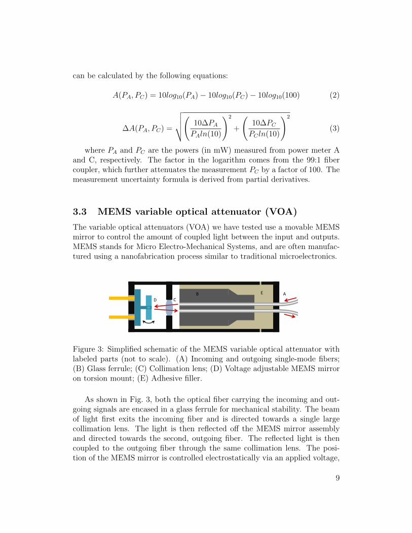
3.3 MEMS variable optical attenuator (VOA)
The variable optical attenuators (VOA) we have tested use a movable MEMSmirror to control the amount of coupled light between the input and outputs.MEMS stands for Micro Electro-Mechanical Systems, and are often manufac-tured using a nanofabrication process similar to traditional microelectronics.
A B C D
E
Figure 3: Simplified schematic of the MEMS variable optical attenuator withlabeled parts (not to scale). (A) Incoming and outgoing single-mode fibers;(B) Glass ferrule; (C) Collimation lens; (D) Voltage adjustable MEMS mirroron torsion mount; (E) Adhesive filler.
As shown in Fig. 3, both the optical fiber carrying the incoming and out-going signals are encased in a glass ferrule for mechanical stability. The beamof light first exits the incoming fiber and is directed towards a single largecollimation lens. The light is then reflected off the MEMS mirror assemblyand directed towards the second, outgoing fiber. The reflected light is thencoupled to the outgoing fiber through the same collimation lens. The posi-tion of the MEMS mirror is controlled electrostatically via an applied voltage,
9

which changes the amount of light coupled to the outgoing fiber [24]. Thisprocess achieves adjustable attenuation between the input and output fibersin the range of approximately 0dB to >50dB.
A total of 8 variable optical attenuators (VOA) have been provided bythe third-party participant for our experiment. These attenuators are all ofthe MEMS type, with 4 being from one manufacturer and the other 4 from aseparate manufacturer, labelled type A or B, respectively. These attenuatorsare arranged in pairs on a PCB (with attenuators from the same manufacturersharing the same PCB), making 4 PCBs in total for the 8 attenuators to betested. The VOA’s are are attached using a soft silicone glue to the PCBassembly, providing a thermally accurate representation of the actual QKDsystem. Due to non-disclosure agreements associated with the project, anymanufacturer names and identifying serial number of the attenuators are notshown in this report.
3.4 Experimental procedure
It is a necessity for the seed laser to be turned on before any other component,since the EDFA is only designed for a fixed input power range. The 1550nmseed laser for the EDFA is controlled using a Thorlabs CLD1015 laser driver,and is first turned on to a current of 200mA with thermoelectric temperaturecontrol set to 25°C. For our laser, this corresponds to a measured power of22.98 (±0.01) dBm or approximately 200 mW.
After the seed laser is set to the correct power, the EDFA is switchedon along with the fiber fuse detector. To verify the accuracy of the statedoutput power from the included control software, we first physically measureits power, using power meter B connected directly to the EDFA without the99:1 fiber coupler in between. The results are shown in the following figure.Using least-squares curve fitting, the best fit degree-3 polynomial is given by:
f(x) ≈ −0.0009637x3 + 0.1051x2 − 2.787x+ 45.464 (4)
This is the formula used to determine the actual power from the EDFA forfuture measurements. The difference between the setpoint and the measuredoutput power is due to the EDFA having a minimum amplification gain, ex-plaining the larger difference in the low ranges of output power. Note thatthis method effectively ignores backscattering and any nonlinearities which
10

can occur for a more complex experimental setup. However for our purposes,only a reasonably accurate control of the optical power sent to the attenuatoris sufficient.
20 25 30 35 40Setpoint Power (dBm)
20
25
30
35
40
Mea
sure
d Po
wer (
dBm
) f(x) 0.0009637x3 + 0.1051x22.787x + 45.464
Figure 4: Measured power curve for the EDFA output with a seed laser powerof 200mW, compared to the software setpoint. Red line denotes the idealEDFA power curve.
The EDFA power output is then shut off after the preliminary powercurve measurement. The test laser is turned on and its current set suchthat power meter A measures approximately 7dBm (5mW). This value willbe used throughout the experiment to calculate the attenuation of the VOA.Afterward, the procedure described below is done for each tested attenuator:
1. Establish the attenuation vs. voltage curve for the VOA being tested.This process is done with the EDFA turned off.
2. A testing voltage is determined based on two factors. The first beingthat the VOA needs to be set to a sufficiently high attenuation to preventdamage to the test laser. The second factor is that the attenuation needsto fall reasonably within the value currently used in the targeted QKDsystems. This operation range is given by the participating third-partiescompanies.
11

3. The EDFA is set to a starting value of about 30 dBm (1W). This start-ing power is determined to be below the damage threshold both frommanufacturer specification and previous experiments.
4. The video camera and infrared camera are both started, to record phys-ical and thermal behaviour of the attenuator under optical stress.
5. The EDFA is turned on and maintained at the desired set point, forat least 60 seconds, until the maximum temperature measured by thethermal camera and the measured value at power meters C both reacha stable plateau.
6. The EDFA is turned off with the video and IR cameras remaining on,recording the cooldown process. In the meantime, power meter C is setto log the measured power.
7. Once the measured value at power meter C stabilizes, the video and IRcameras are shut off. The measured optical power is recorded to calculatethe attenuation after optical damage at a given power.
8. If the attenuation after optical damage is similar to the reference attenu-ation, the EDFA power setpoint is incremented by 0.5–1dBm dependingon how close it is to the expected damage threshold (going to step 3).However if the attenuations before and after are significantly different,the experimental scheme is stopped (proceeding to next item).
9. The attenuation vs. voltage curve is measured again (with EDFA turnedoff) and compared with the curve taken in step 1, before any opticaldamage.
Through the first experimental trials, we have noticed that there is a tem-porary increase in attenuation while the VOA is still in thermal disequilibriumright after the laser has been turned off. To confirm whether any change in at-tenuation after optical damage is permanent and not due to thermal reasons,step 9 above is measured several minutes after the EDFA is shut off, whenthe observed attenuation stabilizes and the case temperature returns back toambient as seen from the thermal camera. To further confirm the change inattenuation, an additional measurement is done 2–5 days afterwards.
4 Results and discussion
From our set of 8 attenuators, 6 are tested (3 from each manufacturer), withthe two remaining serving as reference samples for future use. To recapitulate,
12

our experiment aims to verify whether there can be a drop in attenuation fol-lowing optical damage. We can define a successfully “hacked” sample as onehaving a permanent drop in attenuation post-damage, for any given range ofinput voltages within specifications.
# ManufacturerTesting
Voltage (V)AttenuationBefore (dB)
AttenuationAfter (dB)
∆(dB)
Threshold ofDamage (dBm)
1 A 12.0 33.05 35.44 +2.39 36.92 A 12.0 33.88 32.95 −0.93 37.43 A 11.5 32.81 64.28 +31.47 37.94 B 14.0 38.79 32.32 −6.47 35.95 B 14.5 ≈ 68* 58.82 ≈ −9.2 36.46 B 13.5 31.21 22.29 −8.92 34.8
*Measurement near the minimum power range of the power meter
Table 1: Results after optical damage for MEMS VOA samples. Testing volt-age refers to the parameter used in step 2 of the experimental procedure. The∆ column refers to the change in attenuation observed at the testing voltage.
At the testing voltage, 4 out of the 6 attenuators tested exhibited a per-manent drop in attenuation. Furthermore, for 5 out of 6 attenuators, thereexists some voltage range in which the attenuation is decreased post-damage,as shown by the voltage-attenuation curves and histogram in Fig. 5, with anaverage drop in attenuation of 3.3 dB and a maximum of 16.6 dB in sample6. We can deem the optical damage attack to be successful for these range ofvoltages.
Attenuator #3 exhibited a near-total failure, where the attenuation afteroptical damage is dramatically increased from its normal value. Effectively,this is similar to a component failing “open” in electronics. This sample repre-sents a case of total component failure, which is the undesired outcome whenperforming the hypothesized optical damage attack.
The situation of attenuator #5 is peculiar. While first measuring theattenuation-voltage curve by incrementing the applied voltage, the attenua-tion value appears to become latched after 14.5V (before activating the highoptical power). Subsequent voltage adjustments down to even 0V did notchange this measured attenuation. The 14.5V voltage however, does appearto be in the working range for the other attenuators from manufacturer B.Since the applied voltage is close to the maximum voltage specified, it is likelythat the latching observed at this voltage is from to inherent variability in the
13

0 5 10 15
0
10
20
30
40
50
60
Calcu
late
d At
tenu
atio
n (d
B)
Voltage(V)
Sample #1Before DamageAfter Damage
0 5 10 15
Sample #4
(a) Selected VOA voltage-attenuation curves before and after optical damage. Greenarea denotes the voltages at which the attenuation is permanently decrease afteroptical damage. Optical damage is applied at the voltages shown by the blue lines.
8 10 12 14Voltage (V)
15
10
5
0
Chan
ge in
Atte
nuat
ion
(dB)
Sample #1Sample #2Sample #4Sample #5Sample #6
(b) Change in attenuation observed af-ter damage, starting from first voltageat which Attafter < Attbefore
15 10 5 0Change in Attenuation (dB)
0
2
4
6
8
n
y = 3.341s = 4.208N = 22
(c) Histogram of the measured changein attenuation as shown in (b)
Figure 5: VOA voltage-attenuation curves before and after successful opticaldamage attack, showing the permanent drop in attenuation for 5 out of 6samples. Error bars are smaller than the marker size.
14

working voltage range between components. However despite this unexpectedmalfunction, a permanent decrease in attenuation is observed for this sample.
4.1 Possible damage mechanisms
Observing the behaviour of the MEMS VOA under high optical power, thefront end of the VOA casing (end with input/output fibers) has a higher tem-perature, shown in Fig. 6a. This means that the majority of the optical poweris dissipated near the front end of the VOA, corresponding to the extremityof the glass ferrule in Fig. 3. The cap holding the input and output fibersappears to bulge outwards near the threshold of damage (Fig. 6b), possiblypulling the fiber inside the VOA out of alignment with the collimation lens.In a catastrophic damage scenario near 38 dBm (≈ 6.3W ), the cap detachesitself from the attenuator casing, with smoke emitted. Since the process ofcoupling a beam of light into a single-mode fiber is highly dependent on therelative positions of the involved optical elements [25], we hypothesize that thestructural deformation under high temperatures is one of the possible causesresponsible for the observed change in attenuation.
Following successful optical damage, one VOA is physically disassembledto check for traces of damage. The result is shown in Fig. 7.
Another possible cause is that for typical MEMS materials used (Si, SiN,SiC, etc.) [26], the operating temperature can induce lattice strain and changeits spring constant [27]. The ductility of polycrystalline Si is reported to in-crease at temperatures near 500°C [27]. Thus since the MEMS micromir-ror used in the VOA is fixed using a torsion mount, the amount of deflec-tion induced by a given voltage can change with temperature. The voltage-attenuation curve will be different once the VOA heats up and exceeds itsproper operating temperature range, which can either result in a drop in at-tenuation or an increase, depending on the exact material behaviour underhigh temperature. Our observations using the thermal camera show that theouter casing of the VOA reached 120°C at the damage threshold power. How-ever, from the observations and physical disassembly, it appears that the areanear the fiber end of the VOA is visibly more affected by thermal damage,which attributes some doubt to this mechanism of damage.
15

t=50s
t=230s
t=110s
t=290s
t=350s
t=170s
0s
60s
180s
270s
120s
360s
Time 20°C
140°C
EDFA ON
EDFA OFF
(a) Temperature profile of the VOA frommanufacturer B near the threshold of dam-age. The high power laser was set to 34.5dBm (2.8 W) and turned on between t = 0sand t = 250s.
(b) Overview of MEMS VOA test-ing. Top-left: Cap for a MEMSVOA sample before damage. top-right: Displaced cap for a catas-trophically damaged VOA.
Figure 6: Temperature profile and physical deformation of a typical MEMSVOA under optical damage test.
16

(a) Overview with lid open with boxed areas shown in (b) and (c)
(b) Details of MEMS mirror (c) Details of collimation lens
Figure 7: MEMS VOA from manufacturer A after successful optical damageattack resulting in permanently reduced attenuation. Signs of optical andthermal damage are visible as dark burn marks near the tip of glass sheath.
17
4.2 Real-world attack scenario
In an actual QKD network, the laser damage attack can be effectively con-ducted by an eavesdropper Eve attempting to compromise a given Alice node.Eve would have an EDFA setup similar to the one used in our experiment, andwould proceed by cutting the fiber line and splicing her EDFA at the otherend of Alice, removing Bob from the line entirely. Eve will then turn on theEDFA and increment the optical power applied, while monitoring the signalpower from Alice. Once Alice’s signal power spontaneously rises due to opticaldamage of the VOA, the EDFA is turned off and removed from the fiber line,with the line connected back to Bob. This attack however, is not withoutrisks, as attenuators can also catastrophically fail under a high optical power,which results in an interrupted fiber line and a damaged QKD system for Al-ice. The necessary denial-of-service from the attack is also likely to trigger analert from Alice and Bob.
4.3 Possible countermeasures
To prevent the laser damage attack against optical attenuators, a method ofdetecting or limiting the maximum power through optical fibers is needed. Ananalogous electronics element accomplishing a similar function for electricalcurrent is the fuse. An optical version of the current-limiting fuse has beenproposed using a TeO2 soft glass segment inserted inline of a standard fiber,which can prevent pulses higher than approximately 1W (on the range of 1s)to pass through [28]. A high powered laser from Eve would then trigger theoptical fuse and cut off the fiber path. This scheme has the advantage of beinga simple and robust device, compared to possible active monitors for opticalpower, but would however result in denial of service in case of an attack.
5 Concluding remarks
From our experiments, we have confirmed that it is possible for the variableoptical attenuators (VOA) used in QKD to exhibit a permanent attenuationdrop after optical damage. For 5 of our samples, the average attenuation dropis 3.3 dB with a maximum of 16.6 dB. This attenuation decrease can be in-duced at a distance from the fiber network side by an attacker Eve equippedwith a high powered laser. Our experiments effectively shows that the vari-able optical attenuator (VOA) does indeed represent a vulnerability which can
18

potentially be exploited by an external attacker having access to the fiber net-work.
As for future work, further tests can be made to distinguish whether theprimary cause for the observed damage is directly from the effect of hightemperatures. For example, one could heat the entire MEMS VOA withoutapplying high powered laser, and measure the resulting attenuation. There isalso the possibility of testing the laser damage attack in a live QKD systeminstead of individual attenuator components.
6 Acknowledgements
This work would not have been possible without the guidance and supportof Anqi Huang and Professor Vadim Makarov from the Quantum HackingGroup at the University of Waterloo. We also thank previous undergraduatestudent Krtin Kumar for constructing the fiber fuse monitor, and also thethird-party participants for providing their respective attenuator assembliesfor our experiment.
19

References
[1] C. H. Bennett. Quantum cryptography using any 2 nonorthogonal states.Phys. Rev. Lett., 68(21):3121–3124, 1992.
[2] C. H. Bennett and G. Brassard. Quantum cryptography: Public keydistribution and coin tossing. In Proc. IEEE International Conferenceon Computers, Systems, and Signal Processing (Bangalore, India), pages175–179, New York, 1984. IEEE Press.
[3] Shihan Sajeed, Igor Radchenko, Sarah Kaiser, Jean-Philippe Bourgoin,Anna Pappa, Laurent Monat, Matthieu Legre, and Vadim Makarov. At-tacks exploiting deviation of mean photon number in quantum key dis-tribution and coin tossing. Phys. Rev. A, 91:032326, 2015.
[4] Anqi Huang, Shihan Sajeed, Poompong Chaiwongkhot, Mathilde Sou-carros, Matthieu Legre, and Vadim Makarov. Testing random-detector-efficiency countermeasure in a commercial system reveals a breakable un-realistic assumption. IEEE J. Quantum Electron., 52(11):8000211, 2016.
[5] Vadim Makarov, Jean-Philippe Bourgoin, Poompong Chaiwongkhot,Mathieu Gagne, Thomas Jennewein, Sarah Kaiser, Raman Kashyap,Matthieu Legre, Carter Minshull, and Shihan Sajeed. Creation of back-doors in quantum communications via laser damage. Phys. Rev. A,94:030302, 2016.
[6] C. H. Bennett, F. Bessette, L. Salvail, G. Brassard, and J. Smolin. Ex-perimental quantum cryptography. J. Cryptology, 5:3–28, 1992.
[7] G.A. Wellbrock, T.J. XIA, and D.Z. CHEN. Quantum key distributionsystem, July 16 2013. US Patent 8,488,790.
[8] Gilles Brassard, Norbert Lutkenhaus, Tal Mor, and Barry C. Sanders.Limitations on practical quantum cryptography. Phys. Rev. Lett.,85:1330–1333, Aug 2000.
[9] Norbert Lutkenhaus. Security against individual attacks for realisticquantum key distribution. Phys. Rev. A, 61:052304, Apr 2000.
[10] L. S. Huang, S. Adhikarla, D. Boneh, and C. Jackson. An experimentalstudy of tls forward secrecy deployments. IEEE Internet Computing,18(6):43–51, Nov 2014.
20

[11] Lance Fortnow. The status of the p versus np problem. Commun. ACM,52(9):78–86, September 2009.
[12] Stefan Wolf. Unconditional Security in Cryptography, pages 217–250.Springer Berlin Heidelberg, Berlin, Heidelberg, 1999.
[13] David Kahn. The Codebreakers. Macmillan, 1996.
[14] Zia Ahmed Ron Rivest. Computer and Network Security Lecture 2. MIT,1997.
[15] Charles H. Bennett, Gilles Brassard, and Jean-Marc Robert. How toReduce your Enemy’s Information (extended abstract), pages 468–476.Springer Berlin Heidelberg, Berlin, Heidelberg, 1986.
[16] Charles H. Bennett, Francois Bessette, Gilles Brassard, Louis Salvail, andJohn Smolin. Experimental quantum cryptography. Journal of Cryptol-ogy, 5(1):3–28, Jan 1992.
[17] Charles H. Bennett, Gilles Brassard, and Jean-Marc Robert. Privacy am-plification by public discussion. SIAM Journal on Computing, 17(2):210–229, 1988.
[18] Sharon Goldwater. Quantum Cryptography and Privacy Amplification.SRI International, 1996.
[19] Bruno Huttner, Nobuyuki Imoto, Nicolas Gisin, and Tsafrir Mor. Quan-tum cryptography with coherent states. Phys. Rev. A, 51:1863, 1995.
[20] R Kashyap and KJ Blow. Observation of catastrophic self-propelled self-focusing in optical fibres. Electron. Lett., 24:47–49, 1988.
[21] D. P. Hand and P. St. J. Russell. Solitary thermal shock waves and opticaldamage in optical fibers: the fiber fuse. Opt. Lett., 13(9):767–769, Sep1988.
[22] Woosung Ha, Yoonseob Jeong, and Kyunghwan Oh. Fiber fuse effect inhollow optical fibers”. Opt. Lett., 36(9):1536–1538, May 2011.
[23] Raman Kashyap. The fiber fuse - from a curious effect to a critical issue:A 25th year retrospective”. Opt. Express, 21(5):6422–6441, Mar 2013.
[24] A.A. Godil. Micro electro mechanical system using comb and parallelplate actuation, January 4 2011. US Patent 7,863,799.
21

[25] J. Martin. Coupling Efficiency and Alignment Sensitivity of Single ModeOptical Fibers. University of Central Florida, 1979.
[26] Loughborough University. An Introduction to MEMS (Micro-electromechanical Systems). PRIME Faraday Partnership, 2002.
[27] William N. Sharpe. Tensile testing of mems materials at high tempera-tures. In Advances in Experimental Mechanics IV, volume 3 of AppliedMechanics and Materials, pages 59–64. Trans Tech Publications, 9 2005.
[28] Shin ichi Todoroki and Satoru Inoue. Observation of blowing out in lowloss passive optical fuse formed in silica glass optical fiber circuit. JapaneseJournal of Applied Physics, 43(6A):L728, 2004.
22