Large Twin-Fuselage Cargo Transport Airplane Approach and ... · Large Twin-Fuselage Cargo...
88
NASA Technical Paper 21 83 November 1983 NASA NASA I TP I 2183 c.1 1 I Large Twin-Fuselage Cargo Transport Airplane During Approach and Landing William D. Grantham, Perry L. Deal, Gerald L. Keyser, Jr., and Paul M. Smith .- 25th Anniversary 1958-1983 https://ntrs.nasa.gov/search.jsp?R=19840004122 2020-03-04T21:00:28+00:00Z
Transcript of Large Twin-Fuselage Cargo Transport Airplane Approach and ... · Large Twin-Fuselage Cargo...
NASA Technical Paper 21 83
November 1983
NASA
NASA I TP I 2183 c.1 1
I
Large Twin-Fuselage Cargo Transport Airplane During Approach and Landing
William D. Grantham, Perry L. Deal, Gerald L. Keyser, Jr., and Paul M. Smith
.-
25th Anniversary 1958-1983
https://ntrs.nasa.gov/search.jsp?R=19840004122 2020-03-04T21:00:28+00:00Z

TECH LIBRARY KAFB, NM
NASA Technical Paper 21 83
1983
National Aeronautics and Space Administration
Scientific and Technical Information Branch
00b8Ob7
Simulator Study of Flight Characteristics of a Large Twin-Fuselage Cargo Transport Airplane During Approach and Landing
William D. Grantham, Perry L. Deal, and Gerald L. Keyser, Jr. Langley Research Center Hampton, Virginia
Paul M. Smith Ken t ro n In te rn at ion al, Inc. Hampton, Virginia

SUMMARY
A six-degree-of -freedom, ground-based s imulator s tudy has been conducted t o eva lua te t h e low-speed f l i g h t c h a r a c t e r i s t i c s of a twin-fuselage cargo t r a n s p o r t a i rp l ane and t o compare t h e s e c h a r a c t e r i s t i c s with those of a l a rge , s ing le - fuselage ( re ference) t r a n s p o r t configurat ion which was similar t o t h e Lockheed C-5A a i rp lane . The twin-fuselage t u r b o j e t concept s imulated i n t h i s study had a landing weight of approximately 1.3 mi l l ion pounds and was designed t o ca r ry 284 tons of payload 3500 n.mi. a t a Mach number of 0.8 and a c r u i s e a l t i t u d e of 32 0 0 0 f t . The primary p i l o t i n g t a s k w a s t h e approach and landing.
The r e s u l t s of t h i s s tudy ind ica t ed t h a t t h e twin-fuselage cargo t r a n s p o r t a i r - plane had unacceptable low-speed handl ing q u a l i t i e s with no augmentation. In order t o achieve "acceptable" handling q u a l i t i e s , considerable augmentation was required, and although t h e augmented a i rp l ane could be landed under adverse condi t ions, t h e r o l l performance of t h e a i r c r a f t had t o be improved appreciably before t h e handl ing q u a l i t i e s were r a t e d as being " sa t i s f ac to ry . I '
The r o l l performance parameter tQ=30 ( t i m e required t o bank 30°) was examined extensively during t h i s s imulat ion s tudy, and an at tempt was made t o determine t h e maximum value of var ious simulated p i l o t i n g tasks. For such l a rge and unusually configured a i r c r a f t a s t h e sub jec t twin-fuselage concept, t h e ground-based s imulat ion r e s u l t s i nd ica t ed t h a t a value of t$=30 c h a r a c t e r i s t i c s , and when t+=30 is less than 3.8 sec, s a t i s f a c t o r y r o l l response should be a t t a inab le . In order t o accomplish t h i s r o l l performance on t h e simulated twin-fuselage concept, t h e fuse lages had t o be r e loca ted from 50 percent of t h e wing semispan t o 20 percent of t h e wing semispan and, a s t h e fuse l ages were moved inboard, t he a i l e r o n span was increased such t h a t t h e bas i c a i l e r o n e f f ec t iveness c o e f f i c i e n t s were increased by a f a c t o r of 2.17.
t ~ = 3 0 t h a t t h e p i l o t s would accept a s being s a t i s f a c t o r y f o r
l e s s than 6 sec should r e s u l t i n acceptable r o l l response
Because t h e p i l o t s were loca ted s i g n i f i c a n t l y f a r from t h e r o l l a x i s on t h e simulated twin-fuselage conf igura t ions (var ious fuse lage l o c a t i o n s ) , it was evident t h a t t h e r e could be r e l a t i v e l y high levels of normal acce le ra t ion generated during c e r t a i n phases of f l i g h t . These s imulator r e s u l t s i nd ica t ed t h a t t h e response of t h e twin-fuselage conf igura t ions t o atmospheric turbulence would no t be expected t o be any worse than t h e response of present-day t ranspor t s . However, i nd ica t ions w e r e that, i n general , h igher acce le ra t ions were experienced a t t h e p i l o t s t a t i o n when co r rec t ing f o r landing approach l a t e r a l o f f s e t s than f o r co r rec t ions due t o turbulence.
The r e s u l t s of t h e p re sen t s tudy, i n general , agree reasonably w e l l wi th t h e handling q u a l i t i e s c r i t e r i a used €or comparison, except f o r t h e ro l l - acce le ra t ion and r o l l - r a t e c a p a b i l i t y requirements. Also, t h e augmented twin-fuselage concept com- pares favorably with t h e re ference (single-body) t r a n s p o r t , except f o r t h e s e roll c a p a b i l i t y parameters.

INTRODUCTION
Airplanes have continued t o grow t o t h e po in t where a gross weight of a m i l - l i o n pounds is a near r e a l i t y f o r l a r g e t r a n s p o r t a i r c r a f t p resent ly i n se rv i ce ( B e i n g 747 and Lockheed C-5A). Studies of s t i l l l a r g e r a i r c r a f t (up t o 3 mil l ion pounds) have suggested t h a t reducing t h e wing loading t o approximately one-half t h a t of cur ren t l a r g e a i r c r a f t increases t h e volume wi th in t h e wing more r ap id ly than t h e volume required f o r f u e l or payload and, therefore , e l imina tes t h e requirement f o r a fuselage. An i n t e r e s t i n g consequence of such a design approach i s t h e e l imina t ion of t h e fuselage drag and t h e reduct ion i n wing-bending loads r e a l i z e d by d i s t r i b u t i n g t h e a i rp l ane weight a long t h e wing span - thereby providing improvement i n both t h e payload r a t i o and f u e l e f f i c i ency r e l a t i v e t o smaller conventional designs.
A disadvantage of t h e all-wing (span loade r ) design i s t h e very l a r g e s i z e requi red by t h e low wing loading t o accommodate a given payload. As a poss ib l e means of avoiding t h i s disadvantage, an a l t e r n a t e design approach - t h e multibody - i s cur ren t ly under study. Such designs u t i l i z e two o r more d i s c r e t e bodies t o conta in t h e payload which are so loca ted along t h e wing span t o r e a l i z e s u b s t a n t i a l bending- moment r e l i e f and, therefore , "maintain" much of t h e wing-weight advantage of t h e all-wing span loader . capac i ty , it i s bel ieved poss ib l e t o use t h e volume of t h e s m a l l e r bodies more e f f i - c i e n t l y and thereby compensate f o r t h e inherent wetted-area and weight disadvantages of providing t h e same t o t a l volume i n two o r more bodies r a t h e r than a s i n g l e body. Also, t he multibody arrangement i s compatible with use of wing l i f t f l a p s and con- vent iona l t a i l arrangements f o r t r i m and con t ro l ; therefore , wing loadings equal t o those of cur ren t l a r g e a i r c r a f t seem p r a c t i c a l .
I n comparison with single-body a i r c r a f t of t h e same payload
The multibody designs present ly under study d i f f e r from cu r ren t l a r g e a i r c r a f t i n a t l e a s t two f e a t u r e s t h a t can be expected t o have important e f f e c t s on handl ing q u a l i t i e s , e spec ia l ly during t h e approach and landing phase. F i r s t , t h e r e i s t h e higher gross weight (more than double t h a t of t h e C-SA) and t h e r e l a t e d increased dimensions of such items a s t h e wing span, landing gear t r a c k , and cockpi t loca t ion . Second, t h e magnitude of t h e i n e r t i a s and t h e i n e r t i a d i s t r i b u t i o n a r e considerably d i f f e r e n t from those of conventional design and can be expected t o have a s i g n i f i c a n t impact on con t ro l requirements during landing approach.
P i lo t ed s imulat ion s t u d i e s appeared t o o f f e r t h e b e s t means f o r ob ta in ing a preliminary evaluat ion of t h e expected handling q u a l i t i e s of such d iverse a i r p l a n e concepts and t o a s s e s s t h e adequacy of cu r ren t handl ing q u a l i t i e s requirements. Therefore, t h i s paper eva lua tes t h e low-speed f l i g h t c h a r a c t e r i s t i c s of one such multibody (twin-f uselage) j e t t r anspor t a i rp l ane us ing a six-degree-of -E reedom, ground-based s imulator .
The primary objec t ives of t h i s s imulat ion study w e r e t o eva lua te t h e low-speed handling c h a r a c t e r i s t i c s of t h e sub jec t twin-fuselage t r a n s p o r t and t o ob ta in s u f f i c i e n t information t o provide guidance f o r f u t u r e research requirements. Other major ob jec t ives were
1. Compare t h e low-speed dynamic s t a b i l i t y and c o n t r o l c h a r a c t e r i s t i c s of t h e sub jec t twin-fuselage cargo t r anspor t t o those of a l a r g e "reference" t r anspor t configuration. (The re ference a i r c r a f t w a s s i m i l a r t o t h e Lockheed C- 5A. )
2. Determine t h e minimum con t ro l power required f o r s a t i s f a c t o r y maneuvering c a p a b i l i t i e s .
2
-._. ., ._.. . ..... . . . . . . .. I, , -~

3. Develop any augmentation systems necessary t o produce s a t i s f a c t o r y handling q u a l i t i e s .
4. At ta in s o m e i n s i g h t as t o t h e r i d e q u a l i t i e s of t h i s l a rge , unusually con- f igu red a i rp l ane .
5. Evaluate t h e e f f e c t s of various atmospheric condi t ions on t h e a b i l i t y of t h e p i l o t t o make a s a t i s f a c t o r y approach and landing.
6. At ta in some i n s i g h t a s t o t h e minimum s i z e (width) runway required t o land t h i s l a rge , unusually configured a i r c r a f t .
SYMBOLS AND ABBREVIATIONS
Measurements and ca l cu la t ions were made i n U.S. Customary Units, and a l l ca l cu la t ions a r e based on t h e a i r c r a f t body axes. D o t s over symbols denote d i f f e r e n t i a t i o n with r e spec t t o t i m e .
normal acce le ra t ion , g u n i t s an
a l a t e r a l acce le ra t ion , g u n i t s Y
l i f t - c u r v e s lope p e r u n i t angle of a t t ack , pe r rad ian
rolling-moment c o e f f i c i e n t
rolling-moment c o e f f i c i e n t due t o s i d e s l i p , per degree
pitching-moment c o e f f i c i e n t
‘La
‘IB
‘1
‘m
pitching-moment c o e f f i c i e n t p e r u n i t angle of a t t a c k , pe r rad ian
yawing-moment c o e f f i c i e n t a ‘m
‘n
longi tudinal-force c o e f f i c i e n t ‘X
side-force c o e f f i c i e n t ‘Y
ver t i ca l - fo rce c o e f f i c i e n t
C mean aerodynamic chord, f t
9
cz -
acce le ra t ion due t o g rav i ty , f t / s e c 2
h a l t i t u d e , f t
moments of i n e r t i a about X, Y, and 2 body axes, respec t ive ly , 2
IX,IY,IZ
Ixz
s lug - f t
product of i n e r t i a , s lug - f t 2
a u t o t h r o t t l e gain, degrees per knot KA
a i l e r o n c o n t r o l e f f ec t iveness m u l t i p l i e r Ka
3

K P
K P,Y
KV
Kv, I
KWL
K 6P
Ke K 8 , A
K 8 , H
m
n/a
P d
deg r o l l - r a t e gain, deg/s ec
deg/sec commanded r o l l - r a t e gain, deg
ro l l - r a t e - in t eg ra to r gain, deg/deg
deg r o l l - r a t e ga in i n t h e yaw ax i s , deg/sec
deg p i t ch - ra t e gain, deg/sec
deg/s ec in .
commanded p i t ch - ra t e gain,
deg/s ec deg/s ec
p i tch- ra te - in tegra tor ga in ,
a u t o t h r o t t l e v e l o c i t y gain, deg/deg
a u t o t h r o t t l e ve loc i ty- in tegra tor gain, l / sec
wing-leveler gain, deg/deg
p eda 1- t o-rudde r gearing, de g/i n.
p i t c h - a t t i t u d e gain, deg/de g
a u t o t h r o t t l e p i t ch -a t t i t ude gain, deg/deg
deg/s ec deg/sec
pi tch-at t i tude-hold gain,
ro l l -a t t i tude-hold gain, deg/deg
ro l l -a t t i tude-hold f i l t e r gain, l / sec
r 011- coordinat ion gain, de g/deg
lift p e r u n i t angle of a t t a c k pe r u n i t momentum ( iS/mV)CL , per second a
a i rp l ane mass, s lugs
s teady-s ta te normal acce le ra t ion change per u n i t change i n angle of a t t ack f o r an incremental ho r i zon ta l - t a i l de f l ec t ion a t cons tan t a i r speed , g uni t s / rad
per iod of Dutch r o l l o s c i l l a t i o n , sec
4

S
T
R 2
A L
V
vs
W
X'
- X
Y
i. Y'
- Y
per iod of l ong i tud ina l phugoid o s c i l l a t i o n , s e c
per iod of l ong i tud ina l short-per iod o s c i l l a t i o n , sec
r o l l i n g , pi tching, and yawing angular v e l o c i t i e s , respec t ive ly , deg/sec o r rad/sec
r o l l r a t e s a t f i r s t and second peaks, respec t ive ly , deg/sec o r rad/sec
dynamic pressure, lbf / f t2
reference wing area, f t 2
Laplace opera tor
t h r u s t , lb f
p i t c h time constant , sec
t i m e t o double amplitude, s e c
time f o r s p i r a l mode t o double amplitude, s ec
t i m e t o achieve 300 bank angle, s e c
i n t e r s e c t i o n of t h e pitch-rate-response maximum-slope tangent l i n e and t h e zero amplitude l i n e , e f f e c t i v e t i m e delay, sec
i n t e r s e c t i o n of t h e pitch-rate-response maximum-slope tangent l i n e and t h e s teady-s ta te p i t ch - ra t e l i n e , sec
e f f e c t i v e rise t i m e parameter,
i nd ica t ed a i r speed , knots o r f t / sec
-t2 - -tl, sec
s t a l l speed, knots
a i rp l ane weight, lb f
l ong i tud ina l d i s t ance from p o i n t a t which g l i d e s lope i n t e r c e p t s runway, f t
longi tudina l d i s t ance from a i r c r a f t cen te r of g rav i ty t o p i l o t s t a t i o n , f t
l a te ra l d is tance from c e n t e r l i n e of runway, f t
l a te ra l ve loc i ty during landing, f t/sec
l a t e r a l d i spers ion margin, d i s tance from ou t s ide of main gear bogie t o a po in t 5 f t from edge of runway with a i r c r a f t a x i s of symmetry on runway cen te r l ine , f t
la te ra l d i s t ance from a i r c r a f t cen te r of g rav i ty t o p i l o t s t a t i o n , p o s i t i v e when p i l o t loca ted t o r i g h t of cen te r of g rav i ty , f t
5

a
B
A
a 6
6
6
C
e
&f
6
6
6
P
r
W
zh E
'd
'Ph
'SP
K
v e r t i c a l d i s t ance from a i r c r a f t cen te r of g r a v i t y t o p i l o t s t a t i o n , p o s i t i v e when p i l o t located'below c e n t e r of grav i ty , f t
angle of a t t a c k , deg
angle of sideslip, deg
f l igh t -pa th angle, deg
increment
a i l e r o n de f l ec t ion , p o s i t i v e f o r r i g h t r o l l command, deg
column def lec t ion , in.
e l eva to r de f l ec t ion , deg
t ra i l ing-edge f l a p def lec t ion , deg
ho r i zon ta l t a i l de f l ec t ion , deg
pedal de f l ec t ion , in.
rudder def lec t ion , deg
wheel de f l ec t ion , deg
glide-slope e r ro r , f t
Dutch r o l l mode damping r a t i o
long i tud ina l phugoid mode damping r a t i o
longi tudina l short-per iod mode damping r a t i o
damping r a t i o of numerator quadra t ic @/6 t r a n s f e r func t ion
pos i t i on of bodies a long wing as a f r a c t i o n of semispan
a
p i t c h a t t i t u d e , deg
i n i t i a l trim (reference) p i t c h a t t i t u d e
magnitude of f i r s t p i t ch - ra t e overshoot, deg/sec
magnitude of f i r s t p i t ch - ra t e undershoot, deg/sec
t r a n s i e n t peak r a t i o
r a t i o of commanded r o l l performance t o app l i cab le r o l l performance requirement
d standard devia t ion
'I; R
6
r o l l mode t i m e constant , sec

angle of r o l l , deg
d w
w Ph
w SP
cb w
heading angle, deg
phase angle expressed as a l a g f o r a cosine representa t ion of Dutch r o l l o s c i l l a t i o n i n s i d e s l i p , deg
undamped na tu ra l frequency of Cutch r o l l mode, rad/sec
undamped n a t u r a l frequency of phugoid mode, rad/sec
longi tudina l short-per iod undamped n a t u r a l frequency, rad/sec
undamped n a t u r a l frequency appearing i n numerator quadra t ic of 1$/6 a t r a n s f e r funct ion, rad/sec
Subscr ipts :
aPP approach
av average
c 9 cen te r of g rav i ty
ge ground e f f e c t
H hold
R landing
29 landing gear
l-MX maximum
osc o s c i l l a t o r y
PS p i l o t s t a t ion
rms r o o t mean square
rs r o l l s p i r a l
ss s teady s t a t e
t d touchdown
Abbreviations :
CTOL conventional take-off and landing
DQ(P1L) p i l o t commanded p i t c h ra te
FAA Federal Aviation Administration
I F R instrument f l i g h t r u l e s
7

ILS
MTBT
PLA
P R
RAH
Rl3F
rms
S A S
SCAS
SCR
SJT
VFR
VMS
WL
instrument landing system
multibody t r anspor t
power l eve r angle
p i l o t r a t i n g
ro l l -a t t i tude-hold mode on
re ference
r o o t mean square
s t a b i l i t y augmentation system
s t a b i l i t y and con t ro l augmentation sys t em
supersonic c r u i s e research
subsonic j e t t r anspor t
v i s u a l f l i g h t r u l e s
Langley Visual/Motion Simulator
wing-leveler mode on
DESCRIPTION O F SIMULATED AIRPLANES
Two d i s t i n c t l y d i f f e r e n t a i rp l ane concepts w e r e simulated during t h e p re sen t study. Three-view sketches of t h e two concepts a r e presented i n f i g u r e s 1 and 2, t h e representa t ive landing m a s s and dimensional c h a r a c t e r i s t i c s and t h e c o n t r o l su r f ace de f l ec t ion and de f l ec t ion r a t e l i m i t s f o r t hese a i r c r a f t a r e presented i n t a b l e I, and t h e aerodynamic da ta used i n t h e s tudy a r e presented i n t a b l e s I1 and 111.
Twin-Fuselage Airplane
The twin-fuselage turbo j e t t r a n s p o r t concept simulated i n t h i s s tudy was devel- oped by t h e Tmckheed-Georgia Company (under a NASA con t rac t ) t o car ry 284 tons of payload 3500 n.mi. a t a Mach number of 0 . 8 and a c r u i s e a l t i t u d e of 3 2 0 0 0 f t . The three-view sketch presented i n f i g u r e 1 i l l u s t r a t e s t h e b a s i c loca t ion of t h e fuse- l ages as being a t 50 percent of t h e wing semispan. T h i s configurat ion was a prelim- inary vers ion o f t h e "optimized" twin-fuselage concepts reported i n re ference 1. The a i rp l ane i s powered by four l a rge , advanced-turbofan engines providing a s t a t i c take- o f f thrust-to-weight r a t i o of 0.162. An example o f t h e est imated engine t h r u s t response c h a r a c t e r i s t i c s used i n t h e s imulat ion i s presented i n f i g u r e 3.
The e f f e c t s of changing t h e spanwise loca t ion of t h e fuse lages w e r e evaluated, and t h e r e s u l t i n g v a r i a t i o n s i n r o l l and yaw i n e r t i a s are presented i n f i g u r e 4 ( a ) . A s t h e fuselages were moved inboard, it w a s assumed t h a t t h e a i l e r o n span could be increased as a d i r e c t funct ion of t h e fuselage re loca t ion . The es t imates of t h e
8

increased r o l l con t ro l de r iva t ives were made using t h e methods presented i n r e fe r - ence 2 and a r e ind ica t ed as mul t ip l i e r s (K,) i n f i g u r e 4 ( b ) , where Ka i s va r i ed from 1.0 t o 2.17. However, as t h e fuse lages w e r e moved inboard and t h e a i l e r o n span increased f o r a given t r a i l i ng -edge f l a p de f l ec t ion , t h e r e w a s an assoc ia ted loss of l i f t due t o t h e loss of t ra i l ing-edge f l a p span. The l i f t increment was gained back by drooping t h e a i l e r o n s 200 and increas ing t h e t r a i l i ng -edge f l a p chord, t h e chord inc rease being a func t ion of t h e fuselage pos i t i on on t h e wing. The simulated repre- s e n t a t i v e landing m a s s and dimensional c h a r a c t e r i s t i c s are presented i n t a b l e I ( a ) , and t h e aerodynamic da ta are presented i n t a b l e 11.
Feference Airplane
A single-fuselage t u r b o j e t cargo t r anspor t , s i m i l a r t o t h e Lockheed C-5A air- plane, w a s simulated during t h i s s tudy t o provide a re ference base from which t h e sub jec t twin-fuselage concept could be evaluated. T h i s re fe rence a i rp l ane w a s powered by fou r turbo j e t engines providing a s t a t i c take-of f thrust-to-weight r a t i o of 0.213. A three-view sketch of t h e a i rp l ane i s presented i n f i g u r e 2, t h e simu- l a t e d r ep resen ta t ive landing mass and dimensional c h a r a c t e r i s t i c s a r e presented i n t a b l e I ( b ) , and t h e aerodynamic da ta are presented i n t a b l e 111.
DESCRIPTION O F SIMULATION EQUIFMENT
The s imulat ion study of t h e two a i rp l ane concepts w a s made using t h e general- purpose cockpi t of t h e Langley Visual/Motion Simulator (VMS). This i s a ground-based motion s imulator with s i x degrees of freedom. For t h i s study it had a t ransport- type cockpi t which was equipped with conventional f l i g h t and engine-thrust con t ro l s and with a f l igh t - ins t rument d isp lay representa t ive of those found i n cu r ren t t r a n s p o r t a i rp lanes . (See f i g . 5.) Instruments t h a t i nd ica t ed angle of a t t a c k , angle of s ide - s l i p , and f l a p angle were a l s o provided. A conventional cross-pointer-type f l i g h t - d i r e c t o r instrument w a s used, t h e command bars ( c ros s p o i n t e r s ) being modeled t o be compatible with t h e proposed microwave landing systems.
The con t ro l fo rces on t h e wheel, column, and rudder peda ls w e r e provided by a hydraul ic system coupled with an analog computer. The system allows f o r t h e usua l var iab le- fee l c h a r a c t e r i s t i c s of s t i f f n e s s , damping, coulomb f r i c t i o n , breakout forces , de t en t s , and i n e r t i a .
The airport-scene d isp lay used an "out-the-window" v i r t u a l image system of t h e beam-split ter , re f lec t ive-mir ror type. (See f i g . 6.1
The motion performance c h a r a c t e r i s t i c s of t h e VMS system possess t i m e l ags of less than 60 msec. A nonstandard washout system, u t i l i z i n g nonl inear coordinated adapt ive motion, was used t o p re sen t t h e motion-cue commands t o t h e motion base. (See r e f . 3.)
A runway "model" w a s programmed t h a t had a maximum width of 267 f t , a t o t a l length of 11 500 f t , roughness c h a r a c t e r i s t i c s , and a s lope from t h e cen te r t o t h e edge represent ing a runway crown. Only a dry runway w a s considered i n t h i s study.
The only a u r a l cues provided w e r e engine noises and landing-gear extension and r e t r a c t i o n noises .
9

TESTS AND PROCEDURES
Two research p i l o t s p a r t i c i p a t e d i n t h e s imulat ion program; each f l e w a l l simu- la ted Configurations and t a sks , and each used s tandard f l i g h t - t e s t procedures i n t h e evaluat ion of t h e handl ing and r i d e q u a l i t i e s . approach and landing. approaches f o r var ious conf igura t ions - with crosswinds, turbulence, wind shea r , gl ide-s lope and l o c a l i z e r o f f s e t s , and engine f a i l u r e as added complicating f ac to r s . The I L S approach w a s i n i t i a t e d with t h e a i r p l a n e i n t h e power-approach condi t ion ( p o w e r f o r l e v e l f l i g h t ) , a t an a l t i t u d e belaw t h e g l i d e s lope, and on course bu t o f f s e t from t h e loca l i ze r . The p i l o t ' s t a s k w a s t o capture t h e l o c a l i z e r and g l i d e s lope and t o maintain them a s c lose ly as poss ib l e while under simulated I F R condi- t i ons . A t an a l t i t u d e of approximately 300 f t , t h e a i r c r a f t "broke out" of t h e simu- l a t e d overcast ; whereupon t h e p i l o t converted t o VFR condi t ions and attempted t o land t h e a i rp l ane v i s u a l l y (with l imi t ed re ference t o t h e f l i g h t instruments) .
The primary p i l o t i n g t a s k w a s t h e The tes ts cons is ted of I F R and s imulated VFR landing
This s tudy, us ing t h e aforementioned evaluat ion procedures, evaluated handling and r i d e q u a l i t i e s by ana lys i s of recorded a i r c r a f t q o t i o n t i m e h i s t o r i e s , ca lcu la- t i o n of var ious f l y i n g q u a l i t i e s parameters, and p i l o t comments on t h e f l y i n g qua l i - t i es of t h e simulated twin-body cargo t r anspor t and t h e e f f e c t s of var ious s t a b i l i t y and con t ro l augmentation systems on t h e s e c h a r a c t e r i s t i c s . The more s i g n i f i c a n t r e s u l t s are reviewed i n t h e following sec t ions .
RESULTS AND DISCUSSION
The r e s u l t s of t h i s s tudy are discussed i n terms of t h e previously s t a t e d objec- t i v e s , and t h e p i l o t r a t i n g s l i s t e d f o r t h e var ious condi t ions evaluated are an average of t h e r a t i n g s from both p i l o t s who flew t h a t p a r t i c u l a r condition. See t a b l e I V f o r t h e p i l o t r a t i n g system used f o r handl ing q u a l i t i e s and t a b l e V f o r t h e turbulence e f f e c t r a t i n g sca l e . Also, t h e r e s u l t s discussed p e r t a i n t o t h e da t a obtained on t h e twin-fuselage configurat ion with t h e fuse lages loca ted a t 50 percent of t h e wing semispan (% = 0.5) un less otherwise noted.
No S t a b i l i t y Augmentation
The average p i l o t r a t i n g assigned t o t h e long i tud ina l handling q u a l i t i e s o f t h e unaugmented a i r p l a n e w a s 5, t h e primary objec t ions be ing ( 1 ) low apparent p i t c h damp- ing, ( 2 ) s luggish i n i t i a l p i t c h response, and ( 3 ) unusually l a r g e p i t c h - a t t i t u d e excursions a s soc ia t ed with changes i n f l aps .
A p i l o t r a t i n g of 10 w a s ass igned t o t h e l a t e r a l d i r e c t i o n a l handling q u a l i t i e s of t h e unaugmented a i rp lane . The major ob jec t ions w e r e ( 1) very s luggish r o l l response, ( 2 ) unacceptably l a r g e s i d e s l i p excursions i n t u r n s , and (3) a l a r g e amount of adverse yaw.
Longitudinal cha rac t e r i s t i c s . - The s t a t i c l ong i tud ina l s t a b i l i t y of t h e sub jec t twin-fuselage t r a n s p o r t a i rp l ane was considered by t h e p i l o t s t o be adequate. (The a i r c r a f t had a s t a t i c margin of 5 percent. ) Also, t h i s conf igura t ion w a s flown on t h e s t a b l e s i d e ( f r o n t s i d e ) of t h e thrus t - requi red curve - t h e v a r i a t i o n of t h r u s t required with v e l o c i t y a(T/W)/?W w a s approximately 0.0003 per knot.
The dynamic s t a b i l i t y c h a r a c t e r i s t i c s of t h i s twin-f uselage configurat ion, f o r t h e approach and landing f l i g h t condi t ions, a r e ind ica t ed i n t a b l e V I ( a ) . Also, t h e
10

short-period undamped n a t u r a l frequency w and damping r a t i o C s of t h e simu- l a t e d twin-fuselage t r a n s p o r t a r e ind ica t ed i n f i g u r e 7 and compares with some present-day j e t t r anspor t s . A s shown i n t a b l e VI (a ) , Cs = 1.2, a value normally considered an ind ica t ion of good p i t c h damping - or possi%ly even overdamping. s h o r t p e r i o d damping r a t io on t h e order of 0.7 i s s a i d t o be a good l e v e l . ) However, a s s t a t e d previously, t h e p i l o t s commented t h a t t h e damping i n p i t c h appeared t o be low f o r t h i s configurat ion.
SP
( A
Figure 8 p re sen t s t w o of t h e most widely used long i tud ina l handling q u a l i t i e s c r i t e r i a . Figure 8 ( a ) shows t h e short-per iod frequency requirement of . reference 4. A s can be seen, t h e r e s u l t s p red ic t ed by t h e c r i t e r i o n agree with t h e r e s u l t s obtained during t h e p re sen t s imulat ion study: acceptable , but no t s a t i s f a c t o r y short-per iod dynamics. Figure 8( b) shows t h e Shomber-Gertsen longi tudina l handl ing q u a l i t i e s c r i t e r i o n of re ference 5. This c r i t e r i o n r e l a t e s t h e a b i l i t y of t h e p i l o t t o change f l i g h t pa th with normal acce lera ton t o t h e f a c t o r parameter and by recognizing t h a t t h e p i l o t ' s mode of c o n t r o l i s not constant f o r a l l f l i g h t regimes, a c r i t e r i o n f o r s a t i s f a c t o r y short-per iod c h a r a c t e r i s t i c s was developed ( r e f . 5) t h a t c o r r e l a t e s wel l with cu r ren t a i r p l a n e experience as w e l l as with t h e r e s u l t s obtained during t h e present twin-fuselage t r anspor t simulation pro- gram. It can be seen from t h e s e two c r i t e r i a t h a t it i s t h e low magnitude of w t h a t causes t h e twin-fuselage configurat ion from being " located" i n t h e s a t i s f a c t o r y regions.
La. By us ing t h i s
SP
The r e l a t i v e l y low value of wsp was brought about by t h e combination of high p i t c h i n e r t i a ( Iy = 95 x lo6 s l u g - f t 2 ) and t h e low l e v e l of s t a t i c s t a b i l i t y (Cma = -0.267). Although it i s not immediately obvious, t h e p i t c h damping of t h e
unaugmented twin-fuselage t r a n s p o r t appeared t o be low t o t h e p i l o t s because of t h e l o w magnitude of t h e short-per iod n a t u r a l frequency. For example, f i gu re 9 p re sen t s t ime-history responses t o var ious column inputs . Figure 9 ( a ) shows t h e p i t ch - ra t e response t o a column step inpu t with zero overshoot i n t h e p i t c h rate, i n d i c a t i n g deadbeat (very high) damping. However, t h e response t o a column pulse ( f i g . 9 ( b ) ) might appear t o t h e p i l o t a s being l i g h t l y damped. The long p i t ch - ra t e t i m e cons tan t (tc = 1.3 sec) would appear t o t h e p i l o t a s s luggish i n i t i a l response, and t h e in t e - g r a l of t h e p i t c h r a t e fol lowing con t ro l r e l e a s e (shaded area) would appear t o t h e p i l o t as an undesired overshoot i n p i t c h a t t i t u d e and, hence, low p i t c h damping. It can be concluded t h e r e f o r e t h a t it i s no t t h e magnitude of t h e damping-in-pitch parameter which i s 1.58/sec, t h a t makes t h e configurat ion response appear t o be l i g h t l y damped, bu t r a t h e r t h e magnitude of ws . For example, i f Csp were 0 . 7 (which i s a good l e v e l ) and 2Cs wsp were s t i l l ?.58/sec, would be 1.13; then, from f i g u r e 8, t h e shor t -per ios dynamic c h a r a c t e r i s t i c s of t g e configurat ion (La/wsp = 0.389) would be pred ic ted as being s a t i s f a c t o r y .
2Cspu5p,
ws
The p i l o t s commented t h a t t h e i n i t i a l p i t c h response t o column inputs was slug- gish. This s luggish response, caused by t h e high p i t c h i n e r t i a , i s i l l u s t r a t e d i n f i g u r e 10, which p resen t s t h e p i t ch - ra t8 response t o a column s t e p input ca l cu la t ed from two-degree-of -f reedom equat ions of motion with a i r speed constrained. Using t h e p i t ch - ra t e response c r i t e r i a of re ference 6, f i g u r e 10 i n d i c a t e s t h a t t h e reason t h e p i l o t s r a t e d t h e p i t c h response as being s luggish was t h e magnitude of t h e "rise t i m e parameter." The re ference 6 c r i t e r i o n d i c t a t e s t h a t t h e p i t ch - ra t e rise t i m e parameter A X of t h e simulated twin-fuselage configurat ion mst be l e s s than 0.91 sec f o r s a t i s f a c t o r y response and less than 2.93 sec €or acceptable response. As noted i n t a b l e V I 1 and f i g u r e 10, t h e p i t ch - ra t e r i s e t i m e parameter f o r t h e unaugmented twin-fuselage t r a n s p o r t ( t a b l e VI I (a ) was 1.58 sec, which p r e d i c t s acceptable , bu t no t s a t i s f a c t o r y , p i t ch - ra t e response c h a r a c t e r i s t i c s ; t h i s agrees
11

with t h e p i l o t s ' r a t i n g of 5 determined on t h e simulator. The p i t c h c o n t r o l power w a s r a t e d acceptable i n s o f a r as t h e longi tudina l c o n t r o l power requirements f o r t h e approach and landing t a s k s are concerned. This is i n agreement with t h e c o n t r o l power requirements c r i t e r i o n of re ference 7, as shown i n f i g u r e 11.
La tera l -d i rec t iona l cha rac t e r i s t i c s . - __.__ As s t a t e d previous ly , t h e p i lo t s assigned a r a t i n g of 10 t o - t h e l a t e r a l - d i r e c t i o n a l handl ing q u a l i t i e s of t h e unaugmented a i r - plane. One primary f a c t o r t h a t cont r ibu ted t o t h e poor p i l o t r a t i n g f o r t h e lateral- d i r e c t i o n a l c h a r a c t e r i s t i c s w a s t h e l a r g e adverse s i d e s l i p experienced during r o l l i n g maneuvers, and t h i s c h a r a c t e r i s t i c i s ind ica t ed i n f i g u r e 12. For a step wheel i npu t , it is des i r ab le t o have ( 1 ) a r a p i d r o l l - r a t e response t h a t reaches a reason- ably s teady-s ta te value with a minimum of o s c i l l a t i o n , ( 2 ) e s s e n t i a l l y zero s i d e s l i p produced by t h e r o l l con t ro l i npu t , and ( 3 ) an immediate response i n heading. How- ever, it i s evident from f i g u r e 12 t h a t f o r a la teral c o n t r o l s t e p inpu t f o r t h i s unaugmented configurat ion, a l a r g e amount of adverse s i d e s l i p i s experienced t h a t washes o u t t h e r o l l ra te i n a s h o r t t i m e and causes apprec iab le adverse yaw ( -9 ) . In addi t ion, t a b l e V I I ( a ) i n d i c a t e s t h a t it t a k e s approximately 12 sec t o bank 30° on t h i s unaugmented a i rp l ane i n t h e landing conf igura t ion and t h a t t h e requirement of re ference 4 i s t ies. T h i s s luggish r o l l response, i n combination with t h e large adverse sideslip, made it impossible f o r t h e p i l o t t o make s a f e landings c o n s i s t e n t l y on t h i s unaug- mented a i rp l ane ; thus , t h e l a t e r a l - d i r e c t i o n a l c h a r a c t e r i s t i c s of t h i s conf igura t ion w e r e rated as being uncontrol lable ( P R = 10). It w a s t h e r e f o r e apparent t h a t con- s i d e r a b l e s t a b i l i t y and con t ro l augmentation would be r equ i r ed t o achieve s a t i s - f ac to ry handling q u a l i t i e s f o r t h e approach and landing p i l o t i n g t a sk .
;b
< 4 sec, even f o r acceptab le handl ing qua l i - t@=30
Augmented Airplane
Based on t h e r e s u l t s obtained f o r t h e unaugmented conf igura t ion , t h e o b j e c t i v e €o r t h e design of t h e s t a b i l i t y and con t ro l augmentation system (SCAS) was t h a t t h e system should provide s a t i s f a c t o r y handl ing q u a l i t i e s (PR < 3.5) a t a l l f l i g h t con- d i t i o n s evaluated during t h e study. A block diagram of t h e SCAS design obtained i s shown i n f i g u r e 13. The s e l e c t e d gains for t h e r o l l and yaw axes SCAS are ind ica t ed i n t a b l e V I I I .
Longitudinally, a high-gain p i t ch - ra t e command/attitude-hold system w a s chosen because ( 1 ) t h e system provided good short-per iod c h a r a c t e r i s t i c s and r a p i d response t o p i l o t i npu t s and ( 2 ) t h e a t t i tude-hold f e a t u r e minimized d is turbances due t o tu r - bulence o r va r i a t ions i n f l a p s and/or t h r u s t .
La te ra l ly , a r o l l - r a t e co"and/att i tude-hold system was employed i n an attempt t o provide a r a p i d r o l l mode and quick uniform response t o p i l o t inpu t s ; t h e a t t i - tude-hold f e a t u r e r e s u l t e d i n a des i r ab le neu t r a l ly stable s p i r a l mode while counter- a c t i n g dis turbances due t o turbulence. In addi t ion , a wings-leveler f e a t u r e w a s provided which automatically leve led t h e wings (I$ = 0) whenever t h e bank angle w a s l e s s than 2 O and t h e wheel was centered. This f e a t u r e r e l i eved t h e p i l o t of t h e t a s k of "hunting" f o r zero bank angle and was p a r t i c u l a r l y u s e f u l when r o l l i n g ou t of a t u r n t o a des i red heading. (See f i g . 13(b) f o r la teral c o n t r o l system. )
Direc t iona l ly , r o l l - r a t e and r o l l - a t t i t u d e feedbacks w e r e used t o provide t u r n coordinat ion and improved Dutch r o l l c h a r a c t e r i s t i c s . (See f i g . 13(c) . )
AII a u t o t h r o t t l e t h a t maintained t h e s e l e c t e d airspeed throughout t h e landing approach w a s a l s o used a s p a r t of t h e normal ope ra t iona l augmentation. (See f i g . 14
12

f o r block diagram of t h e a u t o t h r o t t l e design. ) Since t h e simulated engine dynamics (e.g., f i g . 3) produced very good t h r u s t response, t h e a u t o t h r o t t l e genera l ly main- t a ined t h e des i r ed a i r speed wi th in f 3 knots and considerably reduced t h e p i l o t work- load on t h e landing approach.
Longitudinal cha rac t e r i s t i c s . - The longi tudina l SCAS ( f i g . 13( a ) ) provided p i t c h r a t e propor t iona l t o column d e f l e c t i o n and produced t h e des i r ed c h a r a c t e r i s t i c s of rapid, well-damped responses t o p i l o t inputs , a s wel l as inherent a t t i t u d e s t a b i l i t y . Figure 15 shows t h e improvement i n p i t ch - ra t e response provided by t h e SCAS and com- pares t h e p i t c h response of t h e twin-fuselage t r anspor t with t h e simulated reference a i rp lane . As can be seen, t h e SCAS improved t h e p i t ch - ra t e response of t h e twin- fuselage Configuration appreciably i n t h a t t h e p i t c h t i m e cons tan t was decreased by 50 percent (tc decreased from 1.30 s e c t o 0.65 s e c ) and t h e s teady-s ta te p i t c h ra te commanded by a given column inpu t was increased by 16 percent. It may a l s o be noted t h a t t h e p i t ch - ra t e response of t h e augmented twin-fuselage configurat ion compares favorably with t h e augmented re ference a i rp lane . With t h e augmentation system operat ive, t h e average p i l o t r a t i n g f o r t h e longi tudina l handl ing q u a l i t i e s during t h e ILS approach was improved from PR = 5 t o PR = 2.
Figure 16 compares these conf igura t ions with t h e short-per iod handling q u a l i t i e s c r i t e r i a of re ferences 4 and 5; and a s can be seen, t h e twin-fuselage configurat ion agrees q u i t e wel l with both c r i t e r i a and t h e augmented configurat ion i s i n t h e s a t i s - f ac to ry region.
The low-speed p i t ch - ra t e response c r i t e r i o n shown i n f i g u r e 17, and reported i n reference 8, was based on t h e Shomber-Gertsen c r i t e r i o n of re ference 5. Ind ica t ions a r e t h a t t h e twin-fuselage configurat ion does not meet t h e p i tch- ra te response requirements of t h i s c r i t e r i o n , even when t h e a i rp l ane i s h ighly augmented. (Also note t h a t t h e simulated re ference a i rp l ane does not meet t h i s c r i t e r i o n . ) However, when t h e p i t ch - ra t e response of t h e augmented twin-fuselage configurat ion i s compared with t h e c r i t e r i a of re ference 6, it can be seen from f i g u r e 18 and t a b l e VII (b) t h a t t he pred ic ted c h a r a c t e r i s t i c s were a t s a t i s f a c t o r y l e v e l s - i n agreement with t h e p i l o t s ' assessment of t h e configurat ion.
La te ra l -d i r ec t iona l ~ ~ . . cha rac t e r i s t i c s . - A block diagram of t h e l a t e r a l - d i r e c t i o n a l SCAS i s presented in - f igu re 13. La tera l ly , a r a t e command system provided r o l l r a t e propor t iona l t o wheel pos i t i on ( f i g . 13(b) ), and t h e d i r e c t i o n a l system cons is ted of two t u r n coordinat ion f e a t u r e s ( f i g . 1 3 ( c ) ) . Table VI (a ) shows t h a t t h e m t c h r o l l c h a r a c t e r i s t i c s were improved considerably, (which i n d i c a t e s t h a t t h e Dutch r o l l o s c i l l a t i o n should be much l e s s e a s i l y exc i t ed f o r r o l l con t ro l i n p u t s ) , and t h e damping parameter 0 .004 rad/sec t o 0.060 rad/sec. The improvement i n t h e r o l l response and damping i s indica ted by t h e reduct ion of zR from 2.15 s e c t o 1.33 sec.
w$/wd was increased from 0.676 t o 0.993
cawd w a s increased from
Figure 19 shows t h e improvement i n t h e r o l l - r a t e response provided by t h e SCAS. By e l imina t ion of t h e l a r g e adverse s i d e s l i p , t h e r o l l r a t e a t t a i n e d f o r a given amount of wheel de f l ec t ion was increased appreciably, and t h e heading response w a s immediate (no l a g ) . A comparison of t h e l a t e r a l d i r e c t i o n a l response t o a wheel step f o r t h e augmented twin-fuselage a i rp l ane and t h e simulated reference a i rp l ane ind ica t e s t h a t t h e i n i t i a l rol l - ra te response of t h e twin-fuselage a i rp l ane i s slower than t h e $ response of t h e re ference a i r c r a f t bu t t h a t t h e " f i n a l " 6 response i s f a s t e r f o r t h e twin-fuselage configurat ion. and heading ($ ) response of t h e two configurat ions a r e s imi la r .
Ind ica t ions are t h a t t h e s i d e s l i p ( f3 ) (See f ig . 19. )
13

With t h e SCAS operat ive, t h e average p i l o t r a t i n g f o r t h e l a t e r a l - d i r e c t i o n a l handling q u a l i t i e s on t h e ILS approach, i n c a l m a i r , w a s improved from PR = 10 t o PR = 5. The primary objec t ion of t h e p i l o t s t o t h e l a t e r a l - d i r e c t i o n a l character- istics of t h e augmented twin-fuselage configurat ion w a s t h e " l o w r o l l response."
The r o l l - r a t e response c h a r a c t e r i s t i c s presented i n t a b l e s VI(b) and VII(b) i n d i c a t e t h a t (1) t h e e f f e c t i v e t i m e delay would be expected t o be a t a s a t i s f a c t o r y l e v e l s ince ( 2 ) t h e r o l l mode t i m e cons tan t would be expected t o be a t a s a t i s f a c t o r y l e v e l s ince T~ < 1.4 sec, and ( 3 ) t h e time required t o bank 30° would be expected t o be a t an unacceptable l e v e l s i n c e s t a t e d previously, t h e r o l l response of t h e augmented conf igura t ion w a s r a t e d a s acceptable but no t s a t i s f a c t o r y (PR = 5) . Therefore, t h e parameter t+=30 was examined q u i t e thoroughly during t h e sub jec t s imulat ion s tudy, and t h e r e s u l t s are presented i n t h e form of p i l o t opinion of t h e maximum t o l e r a b l e values of f o r var ious simulated p i l o t i n g tasks.
2, < 0.283 sec ,
t+=30 > 6 sec. However, a s
t+=3o
Evaluation of Roll Performance Requirements
The roll requirements of re ference 4 f o r l a r g e , heavy, low-to-medium maneuver- a b i l i t y a i rp l anes - t h e a i rp l ane c l a s s appl ied t o t h e twin-fuselage configurat ion simulated i n t h e p re sen t s tudy, although it i s much l a r g e r than "normal" c l a s s 111 a i r c r a f t - a r e as follows f o r s a t i s f a c t o r y performance:
1. The r o l l mode t i m e cons tan t T~ s h a l l be no g r e a t e r than 1.4 sec ;
2. The yaw and r o l l con t ro l power s h a l l be adequate t o develop a t least 100 of s i d e s l i p i n t h e power-approach f l i g h t condi t ion , with no t more than 75 percent of t h e a v a i l a b l e r o l l con t ro l power;
3. It s h a l l be poss ib le t o land with normal p i l o t s k i l l and technique i n 90° crosswinds of v e l o c i t i e s up t o 30 knots; and
4. The time required t o bank t h e a i rp l ane 30° s h a l l n o t exceed 2.5 sec .
AS can be seen from t a b l e V I ( a ) , t h e r o l l mode t i m e cons tan t T~ was 1.33 sec f o r t h e augmented twin-fuselage t r a n s p o r t concept. This l e v e l meets t h e requirement of reference 4 f o r s a t i s f a c t o r y performance.
Figure 20 i nd ica t e s t h e crosswind trim c a p a b i l i t y of t h e twin-fuselage config- u ra t ion , and it can be seen t h a t (1) t h e yaw and r o l l c o n t r o l power i s adequate t o develop more than a loo s i d e s l i p with 75 percent of t h e r o l l c o n t r o l power ava i lab le , and ( 2 ) t h e r o l l and yaw con t ro l power crosswinds of v e l o c i t i e s up t o 30 knots f i c i e n t t o meet both of t hese re ference
In addi t ion t o t h e s e requirements, required t o bank t h e a i rp l ane 30° s h a l l t a b l e V I I ( a ) , t h e time required f o r t h e
s s u f f i c i e n t t o t r i m t h e a i r c r a f t i n 900
4 requirements. Therefore, t h e r o l l con t ro l p o w e r i s suf-
however, re fe rence 4 d i c t a t e s t h a t t h e t i m e no t exceed 2.5 sec. As can be seen from augmented twin-fuselage a i rp l ane t o bank 300 -
was 7.8 sec , i n t h e landing configurat ion, which i s more than 3 t imes t h e amount of time allowed f o r s a t i s f a c t o r y roll performance. In f a c t , re fe rence 4 implies t h a t if t h e parameter i s g rea t e r than 6 sec , it i s doubtful t h a t t h e a i r c r a f t could cons i s t en t ly be landed safe ly . However, a s s t a t e d previously, t h e simulated twin- fuselage a i rp l ane with t h e SCAS opera t ive , which r equ i r e s 7.8 s e c t o bank 300, w a s
t4,=30
14

assigned an average p i l o t r a t i n g of 5 (acceptable , bu t no t s a t i s f a c t o r y ) f o r t h e approach and landing t a s k i n calm a i r . ( I t should be mentioned t h a t t h e simulated re ference t r a n s p o r t had a value of g rea t e r than 3 sec, and it i s considered t o be a good f l y i n g machine. ) Furthermore, f i g u r e 21 i n d i c a t e s t h a t when s imulated landing approaches w e r e performed i n 900 crosswinds, t h e p i l o t s f e l t t h a t they could perform s a f e landings on t h e twin-fuselage a i rp l ane i n crosswinds up t o 30 knots and r a t e d t h e r o l l performance a s being acceptable (PR < 6.5) f o r landing i n crosswinds a s high as approximately 25 knots. It was obvious from t h e s e r e s u l t s ( f i g . 21) t h a t although t h e twin-fuselage a i rp l ane could be landed under adverse condi t ions, t h e r o l l performance of t h e a i r c r a f t would have t o be improved appreciably before being r a t e d as s a t i s f a c t o r y (PR < 3.5).
t4=30
Figure 22 p re sen t s t h e average p i l o t r a t i n g assigned t o t h e twin-fuselage t r ans - p o r t concept f o r var ious loca t ions of t h e fuselage along t h e wing span and r e l a t e s t h e s e fuse lage loca t ions t o t h e parameter var ious fuse lage loca t ions i n t a b l e V I I I . ) The p i l o t i n g t a s k was t h e approach and landing i n calm atmospheric condi t ions , and t h e ind ica t ed t i m e s required t o bank 30° a r e f o r t h e "landing" configurat ion and speed: 6, = 50° and VA = 126 knots. These r e s u l t s i n d i c a t e t h a t when t h e fuse lages a r e moved from qb = 0.5 s, = 0.2 (which correspond t o fuse lage separa t ion d i s t ances of 2 0 2 f t and 80.8 f t , r e spec t ive ly ) , t h e time requi red t o bank 300 i s decreased from 7.8 s e c t o 6.1 sec, and t h e p i l o t s ' eva lua t ion of t h e i r a b i l i t y t o land t h e a i rp l ane i n calm a i r va r i ed from PR = 5 (acceptable , bu t unsa t i s f ac to ry ) f o r t h e qb = 0.5 configurat ion t o P R = 3.5 (marginally s a t i s f a c t o r y ) f o r t h e qb = 0.2 configuration. Also, t a b l e VI(b) i n d i c a t e s t h a t t h e r o l l mode t i m e cons tan t -cR was decreased from 1.33 sec t o 0 .71 sec ; t a b l e VII (b) i nd ica t e s t h a t t h e e f f e c t i v e t i m e delay i n t h e r o l l - r a t e response t, remained a t a s a t i s f a c t o r y l e v e l ( L < 0.283 sec) f o r a l l fuselage loca t ions simulated.
t4=30. (Note SCAS gain changes f o r
t o
1
F igu re 4 ( a ) shaws t h a t when t h e fuse lages were moved inboard from qb = 0.5 t o 6
Therefore, an attempt was made t o determine t h e maximum qb = 0 .2 , t h e r o l l i n e r t i a Ix was decreased by more than 60 percent (345 X 10 t o 129 x lo6 s lug - f t2 ) . t o l e r a b l e t i m e requi red t o bank t h e a i r c r a f t 30° i n adverse landing condi t ions; t hese r e s u l t s a r e summarized i n t a b l e I X and f i g u r e 23.
The landing t a s k s simulated included ( 1 ) an a r t i f i c i a l c e i l i n g of 300 f t , ( 2 ) a 200-ft l a t e r a l o f f s e t from t h e extended c e n t e r l i n e of t h e runway ( l o c a l i z e r beam), ( 3 ) a s teady 90° crosswind of 15 knots; ( 4 ) a 16-knot, 90° ho r i zon ta l crosswind shear f o r t h e l a s t 200 f t of a l t i t u d e , and ( 5 ) var ious combinations of t hese four. me landing t a s k s were simulated with t h e fuse lages loca ted a t q b = 0.5 t o q = 0.2 , i n 0.1 increments. Also, a s t h e fuse lages were moved inboard, it was assumed t h a t t h e a i l e r o n span could be increased as a d i r e c t func t ion of t h e fuselage re loca t ion .
b
From t a b l e I X , it may be noted t h a t t h e twin-fuselage a i rp l ane i n t h e qb = 0.2 conf igura t ion w a s cons i s t en t ly r a t e d by t h e p i l o t s as be ing b e t t e r (could accomplish t h e t a s k more e a s i l y ) than t h e re ference (single-body) a i rp l ane . For most landing t a sks , t h e twin-fuselage a i r p l a n e i n t h e b e t t e r than t h e re ference a i rp l ane , although t h e r o l l response (t4=30) w a s n o t near ly a s f a s t f o r e i t h e r of t h e twin-fuselage configurat ions, regard less of whether t h e a i l e r o n span w a s increased ( increased r o l l c o n t r o l ) . The reference a i rp l ane used i n t h i s s imulat ion study was s a i d t o represent a t r anspor t similar t o t h e Lockheed C-5A. Since t h e C-5A is known t o be a "good f l y i n g machine," t h e da t a presented i n t a b l e I X imply t h a t t h e p i lo t s would accept values of on very l a r g e cargo t r a n s p o r t s of t h e future .
qb = 0.3 conf igura t ion w a s a l s o r a t e d
t+=30 much g rea t e r than 3 sec
15

The s imulat ion r e s u l t s presented i n f i g u r e 23 i n d i c a t e t h a t f o r such l a r g e and unusually configured a i r c r a f t as t h e sub jec t twin-fuselage concept, a value of t930 < 6 s e c t 9 3 o < 3.8 sec , s a t i s f a c t o r y r o l l response should be a t t a i n a b l e .
should r e s u l t i n acceptable r o l l response c h a r a c t e r i s t i c s , and when
Airplane Touchdown Variables
In an at tempt t o gain some i n s i g h t as t o t h e minimum runway width requi red f o r opera t ion with large multibody cargo t r anspor t s , 79 s imulated landings involving instrument f l i g h t w e r e analyzed with a breakout a l t i t u d e of 300 f t , wi th and without 200-ft l a t e r a l o f f s e t s , and with and without a steady 15-knot crosswind o r wind shear of 16 knots (8 knots p e r 100 f e e t of a l t i t u d e ) . The r e s u l t s are presented i n t a b l e X and f i g u r e 24.
Figure 24 p resen t s t h e longi tudina l and l a t e r a l d i spers ions of t h e touchdown po in t s (where t h e zero index on t h e longi tudina l s c a l e represents t h e po in t a t which t h e g l i d e s lope i n t e r c e p t s t h e runway) and i n d i c a t e s t h a t t h e longi tudina l and l a t e r a l d i spers ions were f740.60 f t and f31.88 f t , r e spec t ive ly , f o r 95 percent of t h e simulated landings (20). The maximum allowable long i tud ina l and l a t e r a l d i s - pers ions i n touchdown pos i t i on a r e given i n re ference 9, on a 2a b a s i s , a s be ing - +750 f t and 227 f t , respec t ive ly . Therefore, upon comparing t h e da ta presented i n f i g u r e 24 with these c r i t e r i a , it can be seen t h a t t h e longi tudina l touchdown d i s - pers ions f o r t hese simulated landings were acceptable (i740.60 f t compared t o f750 f t ) , bu t t h e l a t e r a l d i spers ion po in t s would be considered marginal (f31.88 f t compared t o +27 f t ) . All landings were performed us ing a v i sua l ly simulated runway 11 5 0 0 f t long and 267 f t wide. t h e ou t s ide dimension of t h e main landing-gear wheels w a s 213.6 f t , leaving, t he re fo re , only 26.7 f t t o t h e edge of t h e 267-ft-wide runway when t h e a i r c r a f t cen te r of g rav i ty was on t h e runway center l ine . Reference 9 suggests t h a t when us ing computer ana lys i s (s imulat ion) f o r landing, t h e outboard landing gear should be no c l o s e r than 5 f t from t h e l a t e r a l l i m i t s of a 150-ft-wide runway; i f t h i s 5- f t "requirement" i s assumed f o r t h e present s imulat ion s tudy , t h a t leaves a l a t e r a l d i spers ion margin of 21.7 f t . configurat ion, t h r e e exceeded t h e 21.7-ft l a t e r a l d i spers ion l i m i t , t hus v i o l a t i n g t h e 5- f t requirement. However, a l l o the r landings with t h e o the r simulated con- f i g u r a t i o n s (var ious values of requirement.
For t h e twin-fuselage conf igura t ion with qb = 0.5,
Of t h e 13 landings performed with t h e qb = 0.5
qb) were acceptable , t hus meeting t h e 5- f t
Table X i nd ica t e s t h a t t h e bank-angle ( $td) and crab-angle (+td) requfrements of reference 10 f o r an acceptable touchdown w e r e m e t , bu t t h e s ink- ra te (-htd) and l a t e r a l - d r i f t - v e l o c i t y (j'ta) limits were s l i g h t l y exceeded on a 20 bas i s . However, it should be mentioned t h a t t h e s ink- ra te l i m i t of 5 € t / s ec was suggested a s a l i m i t f o r passenger comfort, and s i n c e t h e 2a maximum s i n k r a t e of 5.93 f t / s e c i s w e l l below t h e s t r u c t u r a l design limits, t h e s ink r a t e s f o r t h e simulated cargo t r a n s p o r t ( t a b l e X) would be considered acceptable. S imi la r ly , t h e 2a maximum l a t e r a l d r i f t ve loc i ty ( 9 ) of 8.61 f t / s e c could be considered acceptab le if t h e a i r c r a f t were designed w i % t h e caster ing-type crosswind landing gear. t h a t f u t u r e a i rp l anes of t h i s s i z e w i l l have crosswind landing gear . )
(It i s general ly bel ieved
Ride Qua l i t i e s
F l igh t i n rough a i r w a s evaluated by us ing a turbulence model based on t h e Dryden s p e c t r a l form. The root-mean-square value of t h e longi tudina l , lateral, and
16

v e r t i c a l gust-veloci ty components w a s 6 f t / s ec ; t h i s l e v e l was descr ibed by t h e p i l o t s as being r ep resen ta t ive of heavy turbulence.
The p i l o t s commented t h a t t h e r a t i n g f o r t h e approach t a s k on t h e augmented twin-fuselage t r a n s p o r t w a s degraded by one-half when t h e landing approach was made i n t h e simulated heavy turbulence because of t h e increased workload required t o main- t a i n I L S t racking. ( P R increased from 5 f o r calm a i r t o 5.5 i n heavy turbulence.) U t i l i z i n g t h e turbulence e f f e c t r a t i n g s c a l e ind ica t ed i n t a b l e V, t h e twin-fuselage a i rp l ane was assigned a r a t i n g of D.
The rms values of t h e v e r t i c a l and l a t e r a l acce le ra t ions a t t h e p i l o t s t a t i o n of t h e simulated twin-fuselage t r a n s p o r t were ca l cu la t ed during I L S approaches made i n simulated heavy turbulence, and t h e s e values w e r e compared with t h e r i d e q u a l i t y c r i t e r i o n of re ference 11. This c r i t e r i o n r e l a t e s t h e r m s values of Aan and a t o t h e rms values of t h e gus t i n t e n s i t y ( leve l of turbulence) . The response of tKe simulated twin-fuselage cargo t r a n s p o r t configurat ion t o t h e FAA heavy turbulence l e v e l compares favorably with t h e aforementioned c r i t e r i o n , although t h e rms normal acce le ra t ion response a s measured a t t h e p i l o t s t a t i o n , f o r 0.11g l i m i t (0.103g). (See f ig . 25 and r e f s . 11 and 1 2 . ) Because t h e p i l o t s a r e loca ted s i g n i f i c a n t l y f a r from t h e r o l l a x i s on t h e simulated twin-fuselage config- u ra t ions s tudied, it i s evident t h a t t h e r e could be r e l a t i v e l y high l e v e l s of normal acce lera t ion generated during c e r t a i n phases of f l i g h t .
qb = 0.5, approaches t h e
Vibra t iona l acce le ra t ions measured on t h e passenger cabin f l o o r of two j e t t r anspor t s during a t o t a l of 13 f l i g h t s a r e summarized i n re ference 13. The f l i g h t s were made i n normal weather condi t ions and included t ax i ing , take-off , ascent , c ru i se , descent, and landing. Ride v ib ra t ion measurements obtained ind ica t ed t h a t f o r t h e smooth-cruise condi t ion t h e r e were rms acce le ra t ions of 0.008g and peak acce le ra t ions of less than 0.03g i n t h e v e r t i c a l d i r ec t ion . Other f l i g h t condi t ions showed rms acce le ra t ions up t o t h e touchdown l e v e l of 0.12g and peak acce le ra t ions up t o t h e touchdown l e v e l of 0.67g i n t h e v e r t i c a l d i r ec t ion . The maximum i n - f l i g h t measurements occurred during t h e descent mode with an rms acce le ra t ion of 0.09g and a a peak acce le ra t ion of 0.53g. Table X I presents t h e average rms and peak acce lera- t i o n s f o r seven f l i g h t phases and t h e i r respec t ive s tandard deviat ions. The two a i rp l anes used i n t h e tests a r e known t o be q u i t e comfortable, both from ind iv idua l passenger r eac t ion and from wide passenger acceptance. This observation, from re fe r - ence 13, served t o emphasize t h e importance of such f e a t u r e s as durat ion, spectrum, and amplitude d i s t r i b u t i o n , as w e l l as rms and peak acce le ra t ions , i n determining t h e subjec t ive response t o a given v ib ra t ion environment. Analysis of t h e twin-fuselage cargo t r a n s p o r t i n t h e simulated landing conf igura t ions has shown t h a t peak normal acce le ra t ions a t t h e p i l o t s t a t i o n of up t o 0.24g were achieved, but i n l i g h t of t h e aforementioned f ind ings of re ference 13, t h i s level would be s a i d t o be acceptable.
Previous s t u d i e s us ing CTOL j e t t r a n s p o r t a i r c r a f t have shown t h a t t h e r m s a cce l e ra t ion measurements i n t h e l a t e r a l d i r e c t i o n f o r var ious f l i g h t phases have been genera l ly considerably lower than those measured i n t h e v e r t i c a l d i r ec t ion . Stephens, i n re ference 14, analyzed t h e da ta from reference 13 and e s t ab l i shed boundaries which he considered t o be representa t ive of a good-riding, acceptable a i r - t r anspor t a t ion system and which may the re fo re serve a s a re ference base f o r examination of o the r systems. !The acceptable boundaries were e s t ab l i shed a t
(a,) r m s / ( h n ) rms conf igura t ion landing-task r e s u l t s and shows t h e da t a t o be close t o t h e upper l i m i t of a c c e p t a b i l i t y with an average (ay)rms/(Aan)rms of 0.265. Note t h a t t h e r e s u l t s f o r f l i g h t i n heavy turbulence are s i g n i f i c a n t l y better, t h u s i n d i c a t i n g t h a t more r o l l con t ro l w a s requi red t o c o r r e c t f o r landing approach l a t e r a l o f f s e t s from t h e
from 0.125 t o 0.288. Figure 26 p resen t s t h e twin-fuselage-
17

runway c e n t e r l i n e than f o r cor rec t ions due t o turbulence. Table X I 1 p r e sen t s t h e average peak acce le ra t ions and t h e i r respec t ive s tandard devia t ions , based on a s m a l l sampling of landing approaches, f o r t h e four twin-fuselage conf igura t ions s tudied. When comparing t h e normal acce le ra t ion r e s u l t s with t h e f ind ings of re ference 13 and t h e l a t e r a l acce le ra t ion a t t h e cockpi t during r o l l i n g maneuvers with t h e c r i t e r i o n of reference 6, t h e " r ide q u a l i t i e s " of t h e simulated twin-fuselage conf igura t ions would be considered t o be acceptable.
Figure 27 p resen t s t h e l a t e r a l and normal acce le ra t ion t i m e h i s t o r i e s r e s u l t i n g from a 3.8O wheel s t e p input . ( T h i s wheel i npu t was s e l e c t e d from t h e average of t h e rms l e v e l s measured during t h e landing-task s tud ie s . ) These da ta c l e a r l y i l l u s t r a t e t h e normal acce le ra t ion sp ike a t t h e p i l o t s t a t i o n due t o t h e r o l l acce le ra t ion con- t r i bu t ion . It may a l s o be noted from f i g u r e 27 t h a t t h e l a t e r a l acce le ra t ion a t t h e p i l o t s t a t i o n i s more p o s i t i v e ( l e s s nega t ive) than t h a t measured a t t h e a i r p l a n e cen te r of grav i ty . The following equation represents an approximation of t h e la teral acce le ra t ion a t t h e p i l o t s t a t i o n :
.- 2 - Z
.- 2 r x - (P + r ) Y - P +
( ay )ps =( (ay)cg 9
For a p o s i t i v e wheel input , (a ) c g i s negat ive and 6, p, r, and G- are posi- t i v e . Therefore, with t h e p i lo? loca ted a t p o s i t i v e 't and negat ive y and z , t h e l a t e r a l acce le ra t ion a t t h e p i l o t s t a t i o n acce le ra t ion a t t h e a i rp l ane cen te r of g rav i ty
(ay)ps i s l e s s negat ive than t h e l a t e r a l
(ay)cg.
Engine Fa i lure
Latera l -d i rec t iona l con t ro l with a c r i t i c a l engine (outboard) f a i l e d has always been a prime considerat ion i n t h e rudder design f o r multiengine a i rp lanes . Control of asymmetries due t o engine f a i l u r e can be e a s i l y analyzed from s t a t i c condi t ions by c a l c u l a t i n g t h e s teady-s ta te s i d e s l i p angle , bank angle , and con t ro l de f l ec t ions f o r a s t r a i g h t f l i g h t pa th over t h e ground. The t r a n s i e n t responses immediately follow- i n g an engine f a i l u r e , however, p resent problems involving p i l o t r eac t ion t i m e , t h e manner i n which cont ro ls a r e applied, and, of course, t h e a l t i t u d e and conf igura t ion of t h e a i rp l ane a t t h e t i m e of t h e f a i l u r e . IXlring t h e sub jec t s tudy, a t tempts were made t o s imulate t h e wave-off c a p a b i l i t i e s as wel l as continued approaches and land- ings a f t e r an outboard engine f a i l u r e on t h e twin-fuselage t r a n s p o r t a i rp l ane .
The manner i n which an engine was f a i l e d dur ing t h i s study was t h a t which would be considered t h e most severe; t h a t i s , t h e engine w a s f a i l e d instantaneously. =so, t h e configurat ion flown i n each ins tance incorporated what was considered t o be t h e b e s t s t a b i l i t y and con t ro l augmentation system ( S C A S ) evaluated i n t h i s s tudy and an au to th ro t t l e .
Wave-of f c a p a b i l i t y a f t e r engine f a i lu re . - The requirement used f o r eva lua t ing t h e wave-of f c a p a b i l i t y of t h e simulated twin-fuselage t r a n s p o r t a i r p l a n e a f t e r
~
engine f a i l u r e was determined on t h e b a s i s of t h e a i rwor th iness s tandards of r e fe r - ence 15: opera t ing procedure, t h e steady gradien t of climb may not be less than 2.7 percent ( 1.5470), with t h e c r i t i c a l engine inopera t ive and t h e remaining engines a t t h e ava i l ab le take-off power o r t h rus t .
i n t h e approach configurat ion corresponding t o t h e normal a l l -engines-
18

The wave-off c a p a b i l i t y of t h e augmented twin-fuselage a i rp l ane i n t h e approach configurat ion (6f = 300; gear down; requirement i n t h a t a 2.7-percent climb gradien t could be achieved with an outboard engine inopera t ive . However, it should be mentioned t h a t even when t h e landing gear was r e t r ac t ed , approximately 93 percent of t h e a v a i l a b l e t h r u s t , 58 percent of t h e ava i l ab le rudder de f l ec t ion , 13 percent of t h e ava i l ab le a i l e r o n de f l ec t ion , and 75 percent of t h e a v a i l a b l e s t a b i l i z e r de f l ec t ion were requi red t o achieve t h i s climb gradien t and maintain r e c t i l i n e a r f l i g h t . Also, t h e inc rease i n p i l o t workload caused by t h e necess i ty t o r e t r i m a f t e r an engine f a i l u r e degraded t h e p i l o t r a t i n g f o r t h e wave-off t a s k t o 6. conf igura t ion with no engine f a i l u r e . )
Vapp = 138 knots) m e t t h e aforementioned
( A p i l o t r a t i n g of 5 was assigned t o t h i s qb = 0.5
Continued approach and landing _ _ a f t e r . engine f a i lu re . - Attempts w e r e made t o s imulate a continued approach and landing following t h e loss of an outboard engine. The conf igura t ion flown incorporated t h e previously discussed s t a b i l i t y and con t ro l augmentation systems (p i t ch - ra t e command/attitude-hold, r o l l - r a t e command/attitude- hold, and var ious t u r n coordinat ion f ea tu res ) and a u t o t h r o t t l e . A t y p i c a l approach, f o r which t h e number 1 engine w a s f a i l e d a t an a l t i t u d e of 1000 f t , i s presented i n f i g u r e 28. The most i n t e r e s t i n g po in t s ind ica ted a r e t h e excursions from t h e local- i z e r and g l i d e s lope fol lowing t h e engine f a i l u r e . A s can be seen, t h e maximum l a t e r a l displacement from t h e l o c a l i z e r beam ( y ) was approximately 150 f t , and t h e maximum v e r t i c a l displacement from t h e g l i d e s lope beam ( E ~ ~ ) was less than 15 f t .
The p i l o t s commented t h a t t h e loss of a c r i t i c a l engine during an ILS approach posed no problems ( i n s o f a r a s t r ack ing l o c a l i z e r and g l i d e s lope) but t h a t t h e requirement of us ing rudder f o r trimming s i d e s l i p was bothersome. For t h e con- t inued approach t a s k a f t e r an outboard engine f a i l u r e , t h e p i l o t s assigned a r a t i n g of 5.5 t o t h e sub jec t twin-fuselage t r anspor t a i rp l ane with t h e fuselages loca ted a t 50 percent of t h e wing semispan (qb = 0 . 5 ) . (For t h e qb = 0.5 configuration, t h e outboard engines are loca ted a t 71 percent of t h e wing semispan; see t a b l e I ( a ) and f i g . 1 . ) It should be noted t h a t t h i s qb = 0.5 conf igura t ion was assigned a p i l o t r a t i n g of 5 when no f a i l u r e s occurred - primari ly because of t h e l o w rol l response capabi l i ty .
E f f e c t s of Center-of-Gravity Location
As s t a t e d previously, t h e longi tudina l handl ing q u a l i t i e s evaluat ions f o r t h e landing-approach t a s k a t t h e b a s i c center-of-gravity p o s i t i o n (0.25;) r e su l t ed i n a p i l o t r a t i n g of 5 with no augmentation and a p i l o t r a t i n g of 2 with t h e SCAS and a u t o t h r o t t l e operat ive. To eva lua te t h e e f f e c t s of center-of -grav i ty loca t ion on t h e low-speed handl ing q u a l i t i e s , t h e a i rp l ane was flown with increas ing levels of nega- t i v e s t a t i c margin. The technique used t o determine t h e m o s t t o l e r a b l e a f t cen ter - of-gravi ty loca t ion w a s t o determine t h e center-of-gravity pos i t i on a t which t h e p i l o t s evaluated t h e low-speed, longi tudina l handl ing q u a l i t i e s as being s a t i s f a c t o r y with t h e SCAS opera t ive , PR < 3.5, and a l s o a s being acceptable with no augmentation ( P R C 6.5). F i g u r e 29 i nd ica t e s t h a t f o r a center-of-gravity loca t ion of 0.46c, t h e p i l o t s r a t e d t h e landing approach t a s k a s being marginally acceptable (PR = 6.5) with no augmentation and s a t i s f a c t o r y (PR = 3) with SCAS operat ive. Therefore, from con- s i d e r a t i o n s of low-speed long i tud ina l handling q u a l i t i e s , t h e a f t center-of-gravity l i m i t on t h e sub jec t twin-fuselage cargo t r a n s p o r t a i r p l a n e w a s s a i d t o be 0.46; ( 16-percent negat ive s t a t i c margin) .
19

Dynamic S t a b i l i t y Requirements and C r i t e r i a
For s eve ra l years t h e a i r c r a f t indus t ry has been aware t h a t many of t h e e x i s t i n g s t a b i l i t y and con t ro l requirements of a i r c r a f t are outdated because of t h e expansion of f l i g h t envelopes, t h e inc reases i n a i rp l ane s i z e , and t h e u t i l i z a t i o n of complex s t a b i l i t y and c o n t r o l augmentation systems. conducted i n an e f f o r t t o remedy t h i s s i t u a t i o n , t o d a t e e s s e n t i a l l y no c l e a r l y def ined s t a b i l i t y requirements and c r i t e r i a have been e s t ab l i shed f o r a i r c r a f t s i m i l a r t o those of very l a r g e conventional o r multibody cargo t r anspor t s . There- f o r e , i n an e f f o r t t o a i d i n t h e f u t u r e establishment of new s t a b i l i t y requirements, t h e low-speed handl ing q u a l i t i e s parameters of a l a r g e re ference t r a n s p o r t and s e v e r a l multibody t r anspor t conf igura t ions are compared with some e x i s t i n g handl ing q u a l i t i e s c r i t e r i a .
Although research i s present ly being
Two of t h e most widely used longi tudina l handl ing q u a l i t i e s c r i t e r i a are pre- sen ted i n f i g u r e 16. Figure 16 (a ) shows t h e short-per iod frequency requirements of re ference 4 and, a s s ta ted previously, t h e r e s u l t s p red ic t ed by t h e c r i t e r i o n agree with t h e r e s u l t s obtained during t h e present s imulat ion s tud ie s . Figure 16(b) shows t h e Shomber-Gertsen longi tudina l handl ing q u a l i t i e s c r i t e r i o n of re ference 5; t h i s c r i t e r i o n r e l a t e s t h e a b i l i t y of t h e p i l o t t o change f l i g h t pa th with normal acce le r - a t i o n t o t h e f a c t o r La. By us ing t h i s parameter and by recognizing t h a t t h e p i l o t ' s mode of con t ro l i s not constant f o r a l l f l i g h t regimes, a c r i t e r i o n f o r s a t i s f a c t o r y low-speed, short-per iod c h a r a c t e r i s t i c s was developed ( r e f . 5) t h a t c o r r e l a t e s wel l with cu r ren t a i rp l ane experience and i s cons i s t en t with t h e r e s u l t s presented i n f i g u r e 16 (a ) obtained during t h e p re sen t low-speed twin-fuselage t r a n s p o r t s imulat ion p ro gram.
The low-speed p i t ch - ra t e response c r i t e r i o n presented i n f i g u r e 17, and repor ted i n reference 8, w a s based on t h e Somber-Gertsen c r i t e r i o n of reference 5. After a s h o r t t i m e , t he re i s exce l l en t agreement between t h e r e s u l t s obtained during t h e p re sen t s tudy and t h i s low-speed p i t c h response c r i t e r i o n , e spec ia l ly f o r t h e twin- fuse lage concept with pitch-rate-command augmentation. However, i n terms of e f fec- t i v e t i m e delay and t r a n s i e n t peak r a t i o , a s def ined i n re ference 6, t h e s e a i r c r a f t e x h i b i t l e v e l 1 ( s a t i s f a c t o r y ) c h a r a c t e r i s t i c s ; and i n terms of rise t i m e parameter (ref. 6 ) , t h e augmented re ference a i rp l ane and unaugmented twin-fuselage a i r p l a n e have l e v e l 2 (acceptable bu t unsa t i s f ac to ry ) c h a r a c t e r i s t i c s , and t h e augmented twin- fuse lage a i rp l ane has l e v e l 1 c h a r a c t e r i s t i c s . (See f i g . 18 and t a b l e s V I I ( a ) and ( b ) . ) These r e s u l t s suggest t h a t t h e lower boundary of t h e re ference 8 p i t ch - ra t e response c r i t e r i o n ( f ig . 17) should be modified f o r t h i s c l a s s of l a r g e t r anspor t s .
The ro l l -acce lera t ion and r o l l - r a t e c a p a b i l i t y c r i t e r i a f o r t r anspor t a i r c r a f t a r e presented i n f igu res 30 and 31, respec t ive ly , and repor ted i n re ferences 16 and 17. are indica ted i n these f i g u r e s and would not be considered t o be i n agreement with r e s u l t s pred ic ted by these c r i t e r i a .
The var ious configurat ions evaluated during t h e p re sen t s imulat ion study
The bank-angle o s c i l l a t i o n , r o l l - r a t e o s c i l l a t i o n , and s i d e s l i p excursion l imi t a t ions c r i t e r i a of re ference 16 a r e presented i n f i g u r e s 32, 33, and 34, respec- t i v e l y . They r e l a t e t h e phase angle of t h e Dutch r o l l component of s i d e s l i p (+ ) t o t h e measure of t h e r a t i o of t h e o s c i l l a t i n g component t o t h e average conponeat of bank angle and r o l l r a t e , and t o t h e maximum s i d e s l i p excursion. ' The var ious con- f i g u r a t i o n s evaluated during t h e p re sen t s imulat ion study are indica ted i n t h e s e f igu res , and it can be seen t h a t t h e simulated c h a r a c t e r i s t i c s agree w e l l wi th t h e aforementioned criteria.
20

In general , it i s concluded t h a t t h e r e s u l t s of t h e p re sen t s imulat ion study agree reasonably w e l l with t h e handl ing q u a l i t i e s c r i t e r i a used f o r comparison i n t h i s paper, except f o r t h e ro l l - acce le ra t ion and r o l l - r a t e c a p a b i l i t y c r i t e r i a of re ferences 16 and 17. A l s o , it may be noted t h a t t h e augmented twin-fuselage concept compared favorably with t h e re ference (single-body ) t r anspor t , except f o r t h e r o l l - acce le ra t ion and roll-rate c a p a b i l i t y parameters.
CONCLUDING REMARKS
A six-degree-of -freedom, ground-based s imulator s tudy has been conducted t o eva lua te t h e low-speed f l i g h t c h a r a c t e r i s t i c s of a twin-f uselage cargo t r a n s p o r t a i rp l ane and t o compaxe these c h a r a c t e r i s t i c s with those of a l a rge , s ingle-fuselage ( re ference) t r anspor t configuration. The primary p i l o t i n g t a s k w a s t h e approach and landing. This paper has attempted t o summarize t h e r e s u l t s of t h e s tudy which sup- p o r t t h e f ollowing major conclusions.
The average p i l o t r a t i n g assigned t o t h e longi tudina l handl ing q u a l i t i e s of t h e unaugmented twin-fuselage a i rp l ane was 5 (acceptable , bu t unsa t i s f ac to ry ) , t h e primary objec t ions being ( 1 ) low apparent p i t c h damping, ( 2 ) s luggish i n i t i a l p i t c h response, and ( 3 ) unusually l a r g e p i t ch -a t t i t ude excursions assoc ia ted with changes i n f l aps .
A p i l o t r a t i n g of 10 (uncont ro l lab le) was assigned t o t h e l a t e r a l - d i r e c t i o n a l handling q u a l i t i e s of t h e unaugmented a i rp lane . The major ob jec t ions w e r e ( 1 ) very s luggish r o l l response, ( 2 ) unacceptably l a rge s i d e s l i p excursions i n tu rns , and ( 3 ) a l a r g e amount of adverse yaw. Therefore, t h e o v e r a l l low-speed handl ing q u a l i t i e s of t h e unaugmented twin-fuselage cargo t r a n s p o r t concept would be s a i d t o be unacceptable.
The longi tudina l s t a b i l i t y and con t ro l augmentation system, cons i s t ing of a high-gain p i t ch - ra t e command/attitude-hold system and an a u t o t h r o t t l e , developed f o r t h i s twin-€uselage t r a n s p o r t a i rp l ane provided good short-per iod c h a r a c t e r i s t i c s and r ap id response t o p i l o t i npu t s and t h e a t t i tude-hold f e a t u r e minimized dis turbances due t o turbulence o r v a r i a t i o n s i n f l a p s and/or t h r u s t . With t h i s augmentation opera t ive , t h e average p i l o t r a t i n g f o r t h e long i tud ina l handl ing q u a l i t i e s on t h e instrument approach was improved from 5 (acceptable , bu t unsa t i s f ac to ry ) t o 2 ( s a t i s f a c t o r y ) .
La te ra l ly , a roll-rate command/attitude-hold augmentation system was employed i n an attempt t o provide a r a p i d r o l l mode and quick uniform response t o p i l o t inpu t s ; t h e a t t i tude-hold f e a t u r e r e s u l t e d i n a des i r ab le neu t r a l ly s t a b l e s p i r a l mode while counteract ing dis turbances due t o turbulence. Di rec t iona l ly , roll-rate and r o l l - a t t i t u d e feedbacks w e r e used t o provide t u r n coordinat ion and improved Dutch r o l l c h a r a c t e r i s t i c s . With t h i s augmentation system opera t ive , t h e average p i l o t r a t i n g f o r t h e l a t e r a l - d i r e c t i o n a l handl ing q u a l i t i e s on t h e instrument approach, i n c a l m a i r , w a s improved from a 10 (uncont ro l lab le) t o a 5 (acceptab le) . The primary objec t ion of t h e p i l o t s t o t h e low-speed f l i g h t c h a r a c t e r i s t i c s of t h e augmented twin-fuselage conf igura t ion w a s t h e "low r o l l response."
When simulated landing approaches w e r e performed i n 900 crosswinds, t h e p i l o t s f e l t t h a t they could perform s a f e landings on t h e twin-fuselage a i rp l ane i n c ross - winds up t o 30 knots and r a t e d t h e r o l l performance as be ing acceptable ( p i l o t r a t i n g s less than 6.5) f o r landing i n crosswinds as high as approximately 25 knots. It w a s obvious, however, tha t although t h e twin-fuselage a i r p l a n e could be landed
21

under adverse condi t ions, t h e r o l l performance of t h e a i r c r a f t would have t o be improved appreciably before being r a t e d as s a t i s f a c t o r y .
The r o l l performance parameter t$=30 ( t i m e r equ i r ed t o bank t h e a i r c r a f t 300) w a s examined q u i t e thoroughly during t h e sub jec t s imulat ion s tudy, and an at tempt w a s made t o determine t h e maximum value of s a t i s f a c t o r y f o r var ious simulated p i l o t i n g tasks . These ground-based s imulat ion r e s u l t s i nd ica t ed t h a t for such l a r g e and unusually configured a i r c r a f t as t h e
less than 6 sec should r e s u l t i n sub jec t twin-fuselage concept, a value of t acceptab le r o l l response c h a r a c t e r i s t i c s , an$-when t4=30 i s less than 3.8 sec, s a t i s f a c t o r y r o l l response should be a t t a inab le . In order t o accomplish t h i s r o l l performance on t h e simulated twin-fuselage concept, t h e fuse lages had t o be r e loca ted from 50 percent of t h e wing semispan t o 20 percent of t h e wing semispan, and as t h e fuse lages w e r e moved inboard, t h e a i l e r o n span w a s increased such t h a t t h e "basic" a i l e r o n e f f ec t iveness c o e f f i c i e n t s w e r e increased by a f a c t o r of 2.17.
t4=30 t h e p i lo t s would accept as being
-3 0
In an attempt t o gain i n s i g h t as t o t h e minimum runway s i z e requi red f o r operat ion with l a r g e multibody cargo t r anspor t s , 79 s imulated landings involving instrument f l i g h t were analyzed with a breakout a l t i t u d e of 300 f t , with and without 200-ft l a t e r a l o f f s e t s , and with and without a s teady 15-knot crosswind o r wind shear of 16 k n o t s (8 knots p e r 100-feet a l t i t u d e ) . The r e s u l t s i nd ica t ed t h a t t h e longi tudina l and la teral touchdown d ispers ions w e r e f740.60 f t and f31.88 f t , respec t ive ly , f o r 95 percent of t h e simulated landings (20). Upon comparing t h e s e results with e x i s t i n g touchdown-position c r i t e r i a f o r conventional t r a n s p o r t s , it can be s a i d t h a t t h e longi tudina l touchdown d ispers ions f o r t h e simulated landings were acceptable (f740.60 f t compared t o allowable f750 f t ) b u t t h e l a t e r a l d i spers ion po in t s would be considered marginal (k31.88 f t compared t o allowable f27 f t ) .
Because t h e p i l o t s a r e loca ted s i g n i f i c a n t l y f a r from t h e r o l l a x i s on t h e simulated twin-fuselage conf igura t ions (var ious fuse lage l o c a t i o n s ) s tud ied , it w a s evident t h a t t h e r e could be r e l a t i v e l y high l e v e l s of normal acce le ra t ion generated during c e r t a i n phases of f l i g h t . The r e s u l t s of t h i s s imula t ion s tudy i n d i c a t e t h a t t h e response of t h e s e conf igura t ions t o atmospheric turbulence would n o t be expected t o be any worse than t h e response of present-day t r anspor t s . However, t h e p i l o t s commented t h a t t h e pi lot : r a t i n g f o r t h e instrument approach on t h e augmented twin- fuselage concept was degraded by one-half when t h e landing approach was made i n t h e simulated heavy turbulence because of t h e increased workload requi red t o maintain g l i d e s lope and l o c a l i z e r t racking. Also, u t i l i z i n g t h e turbulence e f f e c t r a t i n g scale, t h e twin-fuselage a i rp l ane w a s assigned a r a t i n g of D (moderate d e t e r i o r a t i o n of t a s k performance). These s imulator r e s u l t s a lso ind ica t ed , however, t h a t higher acce lera t ions , i n general , w e r e experienced a t t h e p i l o t s t a t i o n when co r rec t ing f o r landing-approach la teral o f f s e t s from t h e extended runway c e n t e r l i n e than f o r cor rec t ions due t o turbulence.
The wave-off c a p a b i l i t i e s , a s w e l l as continued approaches and landing, w e r e simulated a f t e r t h e f a i l u r e of an outboard ( c r i t i c a l ) engine. The wave-off c a p a b i l i t y of t h e augmented twin-fuselage a i rp l ane i n t h e approach conf igura t ion m e t t h e Federal Aviation Administration requirement i n t h a t a 2.7-percent climb gradien t could be achieved with a c r i t i c a l engine inoperat ive. Also? t h e p i l o t s commented t h a t t h e loss of a c r i t i c a l engine during an instrument approach posed no problems ( i n s o f a r as t r ack ing l o c a l i z e r and g l i d e s lope) bu t t h a t t h e requirement of u s ing rudder f o r trimming s i d e s l i p w a s bothersome.
22

In an e f f o r t t o eva lua te t h e e f f e c t s of center-of-gravi ty loca t ion on t h e l o w - speed handl ing q u a l i t i e s , t h e twin-fuselage a i rp l ane w a s flown with increas ing l e v e l s of negat ive s t a t i c margin. It w a s determined t h a t t h e a f t center-of-gravity l i m i t (from a handling q u a l i t i e s s tandpoin t ) on t h e sub jec t cargo t r anspor t a i rp l ane was 46 percent of t h e wing mean aerodynamic chordl which r ep resen t s a negative s t a t i c margin of 16 percent .
In general , it w a s concluded t h a t t h e r e s u l t s of t h e p re sen t s imulat ion study agree reasonably w e l l with t h e handl ing q u a l i t i e s c r i t e r i a used f o r comparison i n t h i s paper, except f o r t h e ro l l - acce le ra t ion and r o l l - r a t e c a p a b i l i t y requirements. It was a l s o noted t h a t t h e augmented twin-fuselage concept compared favorably with t h e re ference (single-body) t r a n s p o r t except f o r t h e s e rol l . c a p a b i l i t y parameters. It i s f u r t h e r concluded, however, t h a t add i t iona l low-speed research i s requi red i n o rder t o develop a da ta base and t o formulate handl ing q u a l i t i e s and r i d e q u a l i t i e s criteria f o r h ighly augmented and/or unusually configured a i r c r a f t of t h e fu tu re .
Langley Re search Center Nat ional Aeronautics afid Space Administration Hampton, VA 23665 August 4, 1983
23

REFERENCES
1. Moore, J. W.; Craven, E. P.; Farmer, B. T.; Honrath, J. F.; Stephans, R. E . ; and Meyer, R. T. : Multibody A i r c r a f t Study - Volume I. NASA CR-165829, 1982.
2. USAF S t a b i l i t y and Control D a t c o m . Contracts AF33(616)-6460 and F33615-76s-3061, McDonnell Douglas Corp., Oct. 1960. (Revised A p r . 1978. )
3. Martin, D. J., Jr.: A D ig i t a l Program f o r Motion Washout on Langley's Six- Degree-of-Freedom Motion Simulator. NASA CR- 145219, 1977.
4. Mi l i ta ry Spec i f ica t ion - Flying pzali t ies of P i lo t ed Airplanes. MIL-F-8785C, Nov. 5, 1980. (Supersedes MIL-F-8785B, Aug. 7, 1969. )
5. Shomber, H. A . ; and Gertsen, W. M. : mng i tud ina l Handling W a l i t i e s C r i t e r i a : A n Evaluation. A I A A Paper No. 65-780, Nov. 1965.
6. Chalk, C. R.: Recommendations f o r SCR Flying p l a l i t i e s Design Cr i t e r i a . NASA CR-159236, 1980.
7. S t a b i l i t y and Control, F l i g h t Control, Hydraulic Systems and Related S t ruc tu res Cr i t e r i a . Doc. No. D6-6800-5, Boeing Co., Jan. 1970.
8. Sudderth, Robert W. ; Bohn, J e f f G. ; Caniff , Martin A.; and Bennett, Gregory R. : Development of Longitudinal Handling p l a l i t i e s C r i t e r i a f o r Large Advanced Supersonic Aircraf t . NASA CR- 137635, 1975.
9. Automatic Landing Systems (ALS). AC No. 20-57A, FAA, Jan. 12 , 1971.
10. Johnson, Walter A.; and Hoh, Roger H. : Determination of ILS Category I1 Decision Height Window Requirements. NASA CR-2024, 1972.
1 1. Low-Wing-Loading STOL Transport Ride Smoothing F e a s i b i l i t y Study. D3-8514-2 (Contract NAS1-10410), B e i n g Co., Feb. 8 , 1971. (Avai lable a s NASA CR-111819.)
12. Grantham, W i l l i a m D.; Nguyen, Luat T.; Deal, Perry L.; Neubauer, M. J., Jr. ; Smith, Paul M.; and Gregory, Frederick D.: Ground-Based and In-Flight Simulator S tudies of Low-Speed Handling Charac t e r i s t i c s of Two Supersonic Cruise Transport Concepts. NASA TP-1240, 1978.
13. Catherines, John J.; Mixson, John S.; and Scholl , Harland F.: Vibrat ions Measured i n t h e Passenger Cabins of Two J e t Transport Aircraf t . NASA T N D-7923, 1975.
14. Stephens, David G. : Developments i n Ride W a l i t y C r i t e r i a . Noise Contr. Eng., vol . 1 2 , no. 1, Jan.-Feb. 1979, pp. 6-14.
15. Airworthiness Standards: Transport Category Airplanes. FAR Pt. 25, FAA, June 1974.
24

16. Chalk, C. R.; N e a l , T. P. ; H a r r i s , T. M.; P r i tchard , F. E.; and Woodcock, R. J. : Background Information and U s e r Guide f o r MIL-F-8785B(ASG), "Mi l i ta ry Spec i f i ca t ion - Flying Q u a l i t i e s of P i l o t e d Airplanes." AFFDL-TR-69-72, U . S . Air Force, Aug. 1969. (Available from DTIC as AD 860 856.)
17. Aerospace Recommended Prac t ice : Design Objectives f o r F ly ing Q u a l i t i e s of C i v i l Transport Aircraft. ARP 842B, Soc. Automot. Eng., Aug. 1, 1964. Revised NOV- 30, 1970.
25
I

. . . . . .
TABLE 1.- MASS AND DIMENSIONAL CHARACTERISTICS O F SIMULATED TRANSPORT AIRPLANES
(a) Twin-fuselage cargo t r anspor t ; qb = 0.5
Weight. l b f .............................................................. 1 287 5 0 0 Reference wing area. f t 2 ..................................................... 12 980 Wing Span. f t ................................................................ 404.00 Wing leading-edge sweep. deq ..................................................... 26 Reference mean aerodynamic chord. f t .......................................... 44.62
S t a t i c margin. percent ............................................................ 5
............................................................. 95 0 0 0 0 0 0
............................................................. 6 500 000
Center-of-gravity loca t ion . percent E .......................................... 25
Ix. s lug-f t2 ............................................................ 345 0 0 0 000 Iy. s lug - f t 2
s lug- f t2 ............................................................ 431 000 0 0 0 I Z Ixz. s lug - f t 2
Maximum con t ro l su r f ace def lec t ions : 6,. deg ................................................................... 0 t o 50 6,. deg ................................................................ 5 t o -15.5 6,. deg ....................................................................... k25 6,. deg ....................................................................... f 4 0 6,. deg ....................................................................... f35
Marimum con t ro l su r f ace de f l ec t ion r a t e s : &. deg/sec .................................................................. +15 fsh. deg/sec .................................................................. 20.5
deg/sec ................................................................... +25 $e * pa. deg/sec ................................................................... +40 6,. deq/sec ................................................................... f35
Horizon t a 1 t a i 1 : Gross h o r i z o n t a l - t a i l area. f t 2 .............................................. 2200 Mean aerodynamic chordr f t ................................................. 15.86 Distance from cen te r of g rav i ty t o h o r i z o n t a l - t a i l 0.25E, f t ............. 114.47
V e r t i c a 1 t a i 1 : Exposed v e r t i c a l - t a i l area. f t 2 .............................................. 2646 Mean aerodynamic chord. f t .................................................. 32.52 Distance from cen te r of g rav i ty t o v e r t i c a l - t a i l 0.25E, f t ................. 92.42
Engines: La te ra l d i s tance from c e n t e r of grav i ty t o engine c e n t e r l i n e
Outboard. f t ............................................................. 143.00 Inboard. f t .............................................................. 101.00
Outboard. f t ............................................................... 4.00 Inboard. f t .............................................................. -12.00
Ver t i ca l d i s tance from cen te r of g rav i ty t o engine c e n t e r l i n e
26

TABLE I.- Concluded
(b ) Reference t r anspor t
Weight. lb f ................................................................. 579 000 Reference wing area . f t 2 ....................................................... 6200 Wing span. f t ................................................................ 219.20 Wing leading-edge sweep. deg ..................................................... 28 Reference mean aerodynamic chord. f t .......................................... 30.93 Center-of-gravity loca t ion . percent E .......................................... 35 S t a t i c margin. percent ........................................................ 10.77 Ix. s lug - f t ............................................................. 34 900 0 0 0 Iy. Slugef t ............................................................. 40 400 000 Iz. s lug - f t ............................................................. 60 100 000
2 2 2
Ixz. SlUg-ft 2 ................................................................ 60 600
Maximum con t ro l sur face de f l ec t ions : 6,. deg .................................................................. k. deg ................................................................ 6,. deg ................................................................. fir. deg ....................................................................... +35
C f . deg/sec .................................................................. +15 &. deg/sec .................................................................. f0.5 6e. deg/sec ................................................................... +25 Ba. deg/sec ................................................................... +40 6,. deg/sec ................................................................... +35
25 t o 40 2 t o -16.5
15 t o -25 6,. deg ....................................................................... f40
M a + " con t ro l su r f ace de f l ec t ion r a t e s :
Horizontal t a i l : Gross h o r i z o n t a l - t a i l area. ft2 ............................................ 965 . a2 Mean aerodynamic chord. f t ................................................. 15.29 Distance from cen te r of g rav i ty t o ho r i zon ta l - t a i l 0.25E, f t .............. 125.87
Ver t ica l t a i 1 : Exposed v e r t i c a l - t a i l area. f t2 ............................................ 961.07 Mean aerodynamic chord. f t .................................................. 27.95 Distance from c e n t e r of g rav i ty t o v e r t i c a l - t a i l 0.25c, f t ................ 110.15
Engines: La te ra l d i s tance from cen te r of g rav i ty t o engine c e n t e r l i n e
Outboard. f t ............................................................... 61.9 Inboard. f t ................................................................ 39.8
Ver t i ca l d i s t ance from cen te r of g rav i ty t o engine c e n t e r l i n e Outboard. f t ................................................................ 3.3 Inboard. f t ................................................................. 3.3
27

0.0454 0.10 0.15 0.20 0.30 0.40 0.60 0.80 1.0
-
0.00639 .01108 .02316 .04258 .Of3922 . l o292 .14340
0.00397 -00689 -01440 -02647 .04304 -06399 -08916
-0.04057 -.OS821 -.07574 -.09289 -.lo942 -.12506 -.13959
-0.02710 -.03888 -.05059 -.06205 -.07309 -.OS354 -so9323
-0.01347 -.01933 -e02515 -.03084 -.03633 -e04152 -a04635
-0.00783 -.01124 -e01462 -.01793 -a02112 -a02414 -e02694
TABLE 11.- AeRODYNAMIC DATA USED I N SIMULATION OF TWIN-FUSELAGE AIRPLANE CONCEPT
a, deg
-8 -4
0 4 8
12 16
bf = 30°
-0.4507 -a8293
-1.2093 -1.5870 -1.9586 -2.3201 -2.6672
- - - - 6, = 500
.~ ~ ..
-0.4195 -.4381 - -4568 -.4754 - -4940 -.5127 -.5313 ___-
~- -0.1354 -. 1432
- . lo64 -.0254
-1006 -2707 -4860
-0.0350 -.3339 - -3526 -.3712 -.3899 -.4085 - -427 1
C , deq-' '6,
C , deg-' '6,
C , deg-' m'e
-0.00081 -.00040 0
.00040
.00081
.00121 -00160
-0.00574 -a00579 -.00580 -.00579 -.00574 -e00567 -moo558
-0.0150 1
1 -0.00423
-.00371 -.00366 -.00350 -.00294 -. 00 186 0
-8 -4
0 4 8
12 16
.-
- I I i ..
. ..
0 -002 14 .00372 .00777 .O 1428 .02322 .03453 .04811
0.00143 .00248 .00519 .00954 .01551 -02306 .03213
0.00077 .00123 -00258 .00474 .00771 .01146 .01598
0.00041 -00072 -00150 .00276 -00448 .00667 .00929
0.00017 .00030 .00063 .00116 .00188 .00280 -00390
0.00006 .00010 .00020 .00036 .00059 .00087 .00121
-8 -4
0 4 8
12 16
'Zge I I I I I I I
-8 -4
0 4 8
12 16
-0.12095 -.17352 - -22575 -.27688 -.32615 -.37279 -.41606
-0.07520 -. 10788 -a14036 -. 17215 -e20278 -e23179 -.25870
-0.00329 0.00472 -moo614 -.00753 -.00887 -.O 10 14 -a01131
-0.00102 -.00146 -.00190 -.00233 -.00274 -.00314 -.00350
I I I I I I L. L.- 'm
-__
-0.00065 -.00095 -.00124 -. 00 154 -a00183 -.a0212 -a00242
-0.00027 -.00040 -.00052 -.00064 -.00077 -.00089 -.00102
-0.00009 -.00012 -.00016 -.00020 -.00020 -.00028 -.00031
-.01917 -a01192 -.00643 -.02371 -so1474 -.00795 -.02825 -mol756 -.00948 -.03278 -.02038 -.01100 -.03732 -.02320 -so1252
*b deno tes wing span in f e e t .
28

TABLE 11.- Concluded
.- -
-0.1135 -. 1143 -.1146 -. 1143 -.1135 -. 1121 -.1102
I
-0.4329 -.4527 -.4690 -.4814 - .4898 -.4939 - .4937 . . -~
0 .OO 116 .00117 .00117 -00117 -00116 .00115 .00113
-
-0.00016 -.00008 0 .00008 .00016 .00024 .00032 _ _
0.0
__ .- _ _
2 , deq-’ ‘6‘
0.00009 .00016 .00023 .00030 .00037 .00043 .00050 _ _ ~
- , deq-’ % -~
-0.00102 -.00101 -.00100 -.00098 -.00096 -.00093 -.00090
. ___
C , rad-’ P . . -~
-0.12 15 -. 1455 -.1719 -.2005 -.2303 -.2610 -.2921
-. -
-ID’ deq-’
-0.00276 -.00289 -.00300 -.00309 -.00318 -.00324 -.00329
~
0.4219 .4030 -3782 .3481 .3132 .2742 .2319
0.0160 .0080
0 -.0080 -.0160 -.0238 -.0316 .- -
:np, deq-’
0.0019 1 -00171 .00150 .00129 .00106 .00084 .00061
-0.1106 -.0908 - -0745 -.0621 -.0537 -.0496 -. 0498
29
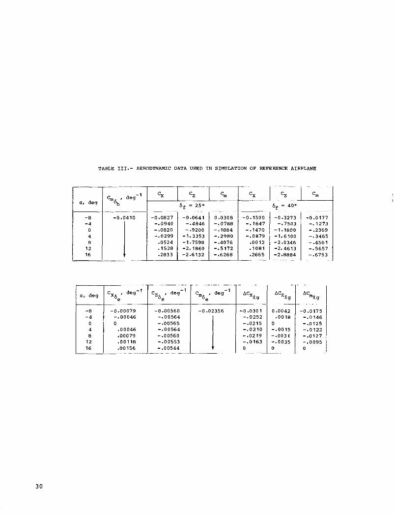
TABLE 111.- AERODYNAMIC DATA USED I N SIMULATION OF REFERENCE AIRPLANE
-0.1500 -. 1647 -.1470 -.0879 .0012
.2665 -1081
_ _ _ _ _
af deg
-0.3273 -.7503
-1.1800 -1.6100 -2.0346
-2.8884 -2.4613
-- -
-8 -4 0 4 8 12 16
-0. 410 -0 -0827 -.0940 -.of320 -.0299 .0524 .1528 -2833
af deg I ‘X6,’ deg-’
-0.00079 -.00046
.00046
.00079 12 .00118 i 16 _ _ -00156
-
-0.0641 -.4846 - -9200 -1.3353 - 1.7598 -2.1860 -2.6132
____. - ~
C z , deg-’ be
-0 -00560 -.00564 -.00565 -a00564 -.00560 -.00553 -.00544
_ _ _ - -
_- 0 -0308 -.0788 - -1884 -.2980 -.4076 -.5172 - -6268
-0 -02356
1 -~
..
-0.0177 -. 1273 - -2369 -.3465 - -456 1 -.5657 - e6753
-0.030 1 -SO252 -.0215 -.0210 - -02 19 -. 0 163 0
Aczlg
0.0042 -0018
0 -.0015 - .003 1 -.0035 0
AC mk
-0.0175 -.0146 -.0125 -.0122 -.0127 -.0095 0
30

TABLE 111.- Continued
60 1 80 1 100 I 130
-8 - 4
0 4 8
12 16
i
-8 - 4
0 4 8
12 16
-8 -4
0 4 8
12 16
160 190 219.2 19
0 -00376 -00320 .0087 1 -02027 .03781 .06121 .09026
-0 -03583 -e07906 -.12233 -. 16502 - -20646 -.24606 -. 283 19
-0 -00886 -. 01997 -.03107 -.04217 -.05330 -.06436 - -07547
40
0 -002 19 -00186 -00507 - 0 1 1 8 1 .02203 .03567 -05260
-0.02088 -.04607 -. 07 130 -.09618 -.12033 -.14341 -.16505
-0.00517 -.01164 -.01811 -.02458 -.03107 -. 03751 - -04398
C Xge
0.00131 .00111 -00303 -00706 .01317 .02131 -03143
-0.01247 -.02753 -.04261 -. 05747 - -07 191 -a08570 - -09863
-0.00309 -.00696 -.O 1082 -. 0 1469 -.01856 -. 02242 -.02628
0 -00084 .00071 -00194 .00452 -00842 -01363 .02011
-0.00798 -.01761 -.02725 -.03676 -.04600 -.05481 -.06308
-0 -00197 -.00445 -.00692 -.00940 -.01187 -. 0 1434 -.O 1681
0.00058 -00049 .00133 -00309 -00576 -00932 .01375
-0.00545 -.01203 -. 0 1862 -.02513 -. 03 143 -.03746 - -04384
~
-0.00135 -.00307 -.00473 -. 00642 -.00811 -.00980 - -0 1 149
0.00035 .00030
-00192 .00358 -00579 .00855
-00082
-0 -00339 -.00749 -.01159 -.01563 -.01956 -.02331 -.02683
-0.00084 -.00189 -.00294 -.00400 -.00505 -.00610 -. 007 15
0.00020 -00017 -00047 .00109 .00204 -00330 -00486
~~
-0.00193 -. 00425 -.00659 -.00889 -.01111 -.01324 -. 0 1524
- 0.00048 -.00108 -.00167 -.00227 -.00287 -.00346 -.00406
0.00009 .00008 .00021 .00049 .00091 -00147 .00217
-0.00086 -.00190 -.00294 -.00397 -.00495 -.00590 -.00680
-0.00021 -.00048 -.00075 -. 0 0 101 -.00128 -.00155 -. 00 18 1
3 1

TABLE 111.- Concluded
-8 -4
0 4 8
12 16
-_
0
l
-24.1
1
a, deg
-8 -4
0 4 8
12 16
6 = 25" f __-__--
0.00176 -00178 -00177 -00176 .00174 .00171 -00168
-0 -00017 -.00004
.00008
.00020
.00033 -00045 -00057
I I
0 . c
a, d e g C, , rad-' I q
I60 -0 .OO 187 -.00187 -.00185 -. 00183 - -00 179 -.00175 -.00170
C , rad- ' yP
c, , rad-' P
-0 -3791 -.3953 -.4100 -.4229 - ,4337 -. 4423 -.4484 .
6 = 40" f
I .-
0.00247 . 0 0 246 .00244 .00240 .00237 .00232 .00225 - .-
0.00002 .00019 -00036 -00053 .00070 .00086 .00102 _ _
-0 -0 129
I -0.0021
-e0023 -.0025 -SO026 -.0028 -.0030 -.0031 -~
.~ I
- ~- - - -0.0893 -. 0991
-.1110 -. 1248 -.1403 -. 1572 -.1751
C I deg-' ~ nP
0.0029 .0028 .0026 -0024 .0022 .0020 .0018 - -.
c , ~ , rad- '
- (a).. .
0.7273 -7060 .6798 -6494 -6153 -5782 -5388
C , rad- ' "r
. ..
-0 -2559 -.2397 -.2250 -.2120 -.2013 -. 1927 -. 1866
aModif ied t o match f l i g h t - t e s t sp i r a l s t a b i l i t y .
32

TABLE IV-- PILOT RATING SYSTEM
May have deficiencies which warrant improvement, but adequate for mission.
Pilot compensation, if required to achieve acceptable perfor- mance, is feasible.
C0"LUBLE
Capable of being controlled or managed in context of mission, with available pilot attention. !
I I \-, SATISFACTORY Excellent, highly desirable. 1
Meets all requirements and expectations: Good, pleasant, well behaved. 2 good enough without improvement.
Fair. Some mildly unpleasant characteristics. 3 Good enough for mission without improvement. ACCEPTABLE I Clearly adequate for mission.
UNSATISFACTORY
Reluctantly acceptable. Deficiencies which warrant improvement. Perfor- mance adequate for mission with feasible pilot compensation.
UNACCEPTABLE
Deficiencies which require improvement. Inadequate performance for mission even with maximum feasible pilot compensation.
UNCONTROLUBLE
Some minor but annoying deficiencies. 4 Improvement is requested. formance is cagily compensated for by pilot.
Effect on per-
Werately objectionable deficiencies. 5 Improvement is needed. Reasonable per- formance requires considerable pilot compensation.
Major deficiencies which require improvement 7 , for acceptance. Controllable. Performance inadequate for mission, or pilot compensa- tion required for minimum acceptable per- formance in mission is too high.
Controllable with difficulty. Requires sub- 8 stantial pilot skill and attention to retain control and continue mission. -
Marginally controllable in mission. 9 Requires maximum available pilot skill and attention to retain control.
Uncontrollable in mission. 10
Very Objectionable deficiencies. Major improvements are needed. Requires best available pilot compensation to achieve
~ acceptable performance.
Control will be lost during some portion of mission.
W W

TABLE V.- TURBULENCE EFFECT RATING SCALE
mcrease of p i l o t e f f o r t with turbulence
N o s i g n i f i c a n t increase
More e f f o r t required
Deter iorat ion of t a s k performance with
turbulence
No s i g n i f i c a n t d e t e r i o r a t i o n
N o s i g n i f i c a n t d e t e r i o r a t i o n
Minor
Moderat e ~
Fbderat e
Best e f f o r t s requi red
Major (bu t evaluat ion t a s k s can s t i l l be accomplished)
Large (some t a s k s can- no t be performed)
Unable t o perform t a s k s
Rating
A
B
C
D
E
F
G
H
34
- . ..... ...

TABLE VI . - DYNAMIC STABILITY CHARACTERISTICS O F SIMULATED LARGE SUBSONIC TRANSPORT AIRPLANES
0 -269 0.240 0.065 24.05 0.116 .
( a ) Twin-fuselage cargo t ranspor t ; qb = 0.5
0.359 0.245 0.0 12 0.244 0.004 0.060 17.53 26.45 0.877 0.123
.~ . ....... 0.705
............... 1.234 ............ 0.679 ... 3.46
w rad/sec Psp, sec
n/a, g uni ts / rad
...........
~
SP
csp La/wsp
~~ . - ~- _ _
Short-period mode ..
1.598 0.629
0.844 1.252 0.300 0.695
3.46 2.89
1.439 7.25
0.799 0.304
2.89
Long-period (aperiodic) mode
Sa t i s fac tory c r i t e r i o n
See f ig . 8 ( a )
0.35 t o 1.30 See f ig . 8 (b ) See f ig . 8 ( a )
_ _ _ _ ~ ~ - __ ~ ~
............ I __ .. -. .-I-- ..... I ..... - t2, sec -
Long-period mode
%hl rad/sec ....... Pph# sec ........... cph ............... -_ - .. . .~
- .~~ ~- -~ ~
oRl sec ............ tsZ l sec ........... wrs, rad/sec ....... crs ............... C r s q - s l rad/sec .... Prsl sec ........... - ~- ~~~
- - ~~
wdl rad/sec ........ cawdl rad/sec ...... Pdl sec ............ ea ................
l$/p ...............
" p o d ............. ............. aAutothrot t le on.
2.01 31.14
0 -385 0.025 0.010 16.33 0.919
0 -690 8.454
Rall-spiral mode --
1.22
1.430 0.485 0.694
5.02 . _ _
Du
~- ...
2.15 30.3 1
:h r o l l mode
-
1.33
1.294 0.449 0.581
5.44 . .~
.~ . - I I
Acceptable c r i t e r i o n
See f ig . 8 ( a )
0.25 t o 2.00 See f ig . 8 (b) See f ig . 8 ( a )
...
(1.4 > 12
>0.5
c3.0 > 8
>0.3
>0.4 > 0 . 0 8 >o. 10
>0.4 >0.02 >0.05
R o l l cont ro l parameters
1 0 . 9 9 1 I 0.676 1 0 . 9 9 T OT8; t o 1.15 1 0.65 t o 1.35 1.022 12.543 0.974
35

TABLE VI.- Continued
war rad/sec ........ cdudl rad/sec ...... P d I sec ............ @/p ...............
ea ................
(b) Effect of fuselage location, basic SCAS, and lateral control system for VA/bf = 126/50
0.245 0.244 0.060 26.45 0.123
[SCAS and autothrottle on]
0 -309 0.253 0.078 21.03 0.088
Parameter I
0 -343 0.259 0.089 18.98 0.109
criterion
Values for %/Ka of - 0.5/1.00 1 0.4/1.00 10.3/1.OO I 0.2/1.00
............. &)dud @/Cd .............
I I
0 .gg3 0.995 0.998 1.001 0.80 to 1.15 0.65 t o 1.35 0.974 0.936 0.902 0.882
T ~ , sec ............ tSZl sec ........... w r s l rad/sec ....... crswrsl rad/sec .... prSr sec ........... crs ...............
1.33
1.294 0.449 0.581 5.44
Roll-spiral mode
1.549 1.908 2.491 0.518 0.615 0.681 0.803 1.173 1.697 >0.5 4.74 4.17 3.45
I Cutch ro l l mode
0 -275 0.247 0.068 23.56 0.120
I F a l l control parameters 1 >0.4
> 0.08 >o. 10
>0.4 >0.02 >0.05
36

TABLE VI.- Continued
(c) Effect of fuselage locat ion, modified SCAS, and l a t e r a l control system f o r V / 6 = 126/50
R f
[SCAS and au to thro t t le on]
. ....... ~ _ _ __ . . . . _ _ _ - ..... Values f o r q,/Ka of -
Pa ramet e r
'cR, sec ............ wrs, rad/sec ....... Crswrs, rad/sec .... Prs, sec ...........
tS2, sec ........... Crs ...............
Roll-spiral mode _ _ ~ 1 . 0 1 - ~ F 7 i - - . - r 8
1- 744 2.447 4.317 0.402 0.488 0.632 0.701 1.194 2.729 3.94 2.94
_____ ______ - -
Dutch r o l l mode ~~
wd, rad/sec ........ Cawd, rad/sec ...... Pd, sec ............ Cd ................
@/p ............... __-_ ~
0.275 0.244 0.067 23.59 0.093
1 I--
0.308 0.244 0 . 0 7 5 21.02 0.067
0 -379 0.248 0.094 17.09 0.075
. .-
Satisfactory c r i t e r ion
-~
C1.4 > 12
> 0 . 5
- -
>0.4 > 0.08 >o. 10
Acceptable c r i t e r ion
C3.0 >8
>0.3
>0.4 >0.02 > 0 . 0 5
m11 control parameters . . . . -
.................. 0 -997 1 .ooo 0.80 t o 1.15- 1 0 .65 t o 1.35 . @/Cd ............. 0.949 0.936 0.937 . . . . ... -
37
' I

I I I I I I1 l l l l l l I 1l111111lllIlII~l1l11111ll
I _ _ _
0.675 18.80 0.869 0.829
3.96
TABLE VI.- Concluded
-.
0.754 0.645 23.79 19.73 0.937 0.870 0.742 0.823
3.96 3.56
(d) Reference t r anspor t
............. 0.824 CdCd ............. 1.951 wd/wd
- - - _ - I Vapp/Gf = 135/25 va/6f = 128/40 ---- I -
Parameter r L ; : ; { Without 1 . S A ~ augmentation augmentation
( a ) -
1.243 1.148 0.857 I 0.818 2.332 1.022 1 . -
w rad/sec ....... Psp, sec ........... SP’
Csp ............... L,/WSP ............ n/a, g uni ts / rad ...
0.706 25.99 0.940 0.752 3.56
Long-period (aperiodic) mode - - _ _ -~ - _.
............ b-35.82 - 1 - - i d _ _ I . t2, sec -
Long-period mode
wph, rad/sec ....... 0.122 ........... ...............
Satisfactory c r i t e r i o n
See f i g . 8(a)
0.35 t o 1.30 See f i g . 8 (b) See f ig . 8 ( a )
>0.04 I I I I
Roll-spiral mode - - - _____
zR, sec ............ tS2, sec ........... wr ra d/se c ....... c r s q s , rad/sec .... Prs, sec ........... Crs ...............
1.75 10.75 10.37
Dutch r o l l mode
wdl rad/sec ........ i& ................ Cdwdl rad/sec ...... l$/p ............... Pd, see ............
0.579 0.432 0.135 0.544 0.078 0.235 10.95 17.33 1.053 0.850
0.553 0.125 0.069 11.44 1.187
-.
3.35 b-3.41
~_ .. -
0.395 0.445 0.176 17.77 0.861
< 1.4 > 12
>0.5
>0.4 > 0 . 0 8 >o. 10
> 6 I
Acceptable c r i t e r i o n
See f i g . 8(a )
0.25 t o 2.00 See f i g . 8 (b) See f ig . 8(a)
> O
< 3.0 > 8
> 0 . 3
> 0 . 4 > 0.02 >0 .05
0 -80 t o 1.15 0.65 t o 1.35 r --
30

TABLE VI1 . - CONTROL RESPONSE CHARACTERISTICS O F SIMULATED LARGE SUBSONIC CRUISE TRANSPORT AIRPLANES
,
Pa lame t er
( a ) Twin-fuselage cargo t ransport ; qb = 0.5
1
V /6, = 138/30 VI/&, = 126/50 aPP
Sat isfactory . Acceptable c r i t e r i o n c r i t e r i o n
SCAS Without
(a 1 (a 1
SCAS Without augment a t ion augmentation
0 .030 See f igure 30
0.937 ' >0.60 0.090 See f igure 32
0.25 CO. 283
6.91 ~
7.8 C2.5
1.58
Longitudinal
See f igu re 30 See f igure 31
>0.25 See f igu re 32
(0.400 (4.0
2 .. OmX, rad/sec .... . . e/ess ............ bnl;f g u n i t s
deg/sec 2 '.'
'l;t . sec ........... *kt sec ........... 1 ~ i ~ / ~ 6 ~ ..........
.. hx, rad/sec2 'kx, deg/sec ..... p2/p 1 ............ oosc/oav t + 3 o f sec ........ tl , sec ...........
9 9 9 ' 9
A,& sec ........... aAutothrott le on.
b-O. 069 b-O. 069
0.05 1.53
0
0.036 4.40
0.154 0 608
10.4 0.26
0.10 1.00
0.13
~~
0.035 7.78
0.930 0.070
7.0 0.26 1.42
b-O. 059
0.05 1.58
0
~~
0.031 3.98
0.157 0 692
12.2 0.25
b-O. 059
0.10 0.88
0.13
b-O. 055
See f igure 17'
(0.200 '0.041 t o 0.909
CO. 30
b-O. 035
*e f igu re 11'
(0 .283 '0.015 t o 2.932
C 0.60
bMinimum demonstrated speed = 1. 06vs. 'Landing configuration.
W 19

P 0
V a l u e s for %/Ka of - 0.5/1.00 10.4/1.00 1 0.3/1.00 10.2/1.00
TABLE V I 1 . - Con t inued
S a t i s f a c t o r y Acceptable c r i t e r i o n c r i t e r i o n
(b) E f f e c t of f u s e l a g e l o c a t i o n , basic SCAS, a n d l a te ra l c o n t r o l s y s t e m f o r VR/6, = 126/50
S e e f i g u r e 30 S e e figure 31
>0 .25
[SCAS and au to thro t t le on]
' ~
Pa ramet er I Lateral I
.. rad/sec2
O b a x , deg/sec ..... p2/p 1 ............ 0 /@a" .......... osc t ~ 3 0 , sec ........ A , , sec ........... AX, sec ...........
0.030 0.039
0.090 0.071
0.25 0.20 1.58 1.35
0.049 7.74
0.991 0.050
6.5 0.23 0.94
0.061 7.90
0.995 0.041
6.1 0.22 0.73
S e e f i g u r e 30
>0.60 S e e f i g u r e 32
( 2 . 5 (0.283

TABLE VI1.- Continued
Pa lame t e r
( c ) Effect of fuselage locat ion, modified SCAS, and l a t e r a l control system f o r VA/6, = 126/50
Values f o r %/Ka of - Satisfactory Acceptable I c r i t e r i o n c r i t e r i o n
0.5/1.00 10.4/1.38 I o * 3 / 1 . 7 4 I0.2/2.17
[SCAS and au to th ro t t l e on]
.. hax . rad/sec2 .... O h a x . deg/sec ..... i p2/p, ............ '
tl, sec ........... 4)osc/4av t k 3 0 , sec ........ A& sec ...........
0.053 8.89
0.963 0.060
5.8 0.17 1.23
0.085 0.131 I 10.64 12.58 ~ 0.989 1.000
0.039 0.020 4.7 3.8
0.25 0 .15 0.75 0.56
Lateral
See f igure 30 See figure 31
>0.25 See figure 32
(4.0 <O. 400 C0.283

TABLE V I I . - Concluded
( d ) Reference t ranspor t
7 1
V /6, = 135/25 VA/Sf = 128/40 aPP
Sat i s fac tory Acceptable c r i t e r i o n c r i t e r i o n Parameter
Without S A S Without SAS augmentation augmentation ( a )
( a ) Longitudinal
2 1 kaxl rad/sec ....
I
. . e/e,, ............. hnl;l g u n i t s
de g / s e c 2 - . *
tl, sec ........... AX, sec ........... Ab2/Ab1 .......... 7 .. kxI rad/sec2 .... 'haxi deg/sec . . p2/p 1 ............ $osC/4)av - t e 3 o I sec ........ k,, sec ........... A%, sec ...........
b-O. 051
0 . 0 5 1.58
0
0.121 15.56 0.865
3.6 0.15
b-O. 051
0.03 1.42
0.14
b-O. 046
0.05 1.71
0
Lateral
0.120 17.25 0.854
3.6 0.15 2.90
0.155 20.86 0.930
3.1 0- 1 6
aAutothrot t le on. bMinimum demonstrated speed = 1. 06vs. 'Landing configuration.
'-0.046
0.03 1.35
0.18
b-O. 055
See f igu re 17c
(0.200 c0.041 t o 0.901
(0.30
I 0 .153 22.52 0.918
3.1 0.16 2.51
See f igu re 30
20.60 See f i g u r e 32
(2 .5 (0. 2 8 3
See f i g u r e 30 See f i g u r e 31
See f i g u r e 32
G0.400
)O. 2 5
(4.0
b-O. 035
See f i g u r e 1 1 ~
< 0.283 '0.014 t o 2.905 -
(0 .60

1
-50.0
-50.0
-50.0
1.0
1.0
1.0
TABLE VII1.- LATERAL-DImCTIONAL SCAS = I N S
R o l l a x i s
~
%#I
9.0
9.0
9.0
12.0
7.0
7.0
7.0
Kp
0.5
.4
.3
.2
0.4
.3
.2 -
15.0
1 10.0
10.0
10.0
Yaw a x i s
~~
Ka
1 .oo
1 6 r R
K qb .. -
0.5
.4
.3
.2
0.4
.3
.2
-14.0
I - 0 -18
1 -6.0
-5.5
-5 - 0
-4.5
1.38
1.74
2.17
-14.0
-14.0
-14.0
-0 18
-0.18
-0.18
-5.5
-5.0
-4.5
43
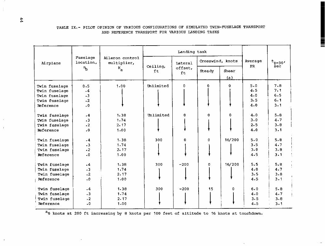
P IP
TABLE I X . - PILOT O P I N I O N O F VARIOUS CONFIGURATIONS OF SIMULATED TWIN-FUSELAGE TRANSPORT AND REFERENCE TRANSPORT FOR VARIOUS LANDING TASKS
Airplane
Twin fuselage T w i n fuselage Twin fuselage T w i n fuselage &f erence
T w i n fuselage Twin fuselage T w i n fuselage &f erence
T w i n fuselage Twin fuselage T w i n fuselage faef erence
T w i n fuselage Twin fuselage T w i n fuselage I&f erence
Twin fuselage Twin fuselage j Twin fuselage faef erence
Fus e l a ge loca t ion ,
YJ
0 e5 .4 .3 .2 .o
.4
.3
.2
.o
.4
.3
.2
.o
.4
.3
.2
.o
.4
.3
.2
.o
Aileron cont ro l mul t ip l ie r ,
Ka
1 .oo
I 1.38 1.74 2.17 1 .oo
1.38 1.74 2.17 1 .oo
1.38 1.74 2.17 1 .oo
1.38 1.74 2.17 1 .oo
Ceiling, f t
Unlimited
I Unlimited
1 1 1
I
300
300
300
Landing task
Lateral o f f s e t ,
f t
0
I 0
I 1 1 1
0
-200
-200
2 0 s s win d, knots
Steady
0 I 0
1 1 1 I
0
0
15
Shear
(a)
0 I 0
1 1 1 1
16/200
16/200
0
tve r ag e PR
5.0 4.5 4.0 3.5 4.0
4.0 3.0 2.5 4.0
5.0 3.5 3.0 4.5
5.5 4.0 3.5 4.5
6.0 4.0 3.5 4.5
t$=30' sec
7.8 7.1 6.5 6.1 3.1
5.8 4.7 3.8 3.1
5.8 4.7 3.8 3.1
5.8 4.7 3.8 3.1
5.8 4.7 3.8 3.1
a O knots a t 200 f t increasing by 8 knots pe r 100 f e e t of a l t i t u d e t o 16 knots a t touchdown.

TABLE X. - VARIABLES AT TOUCHDOWN O F SIMULATED TWIN-FUSELAGE TRANSPORT
Var i ab 1 e . .
X;dI f t
YtdI f t
Average value
875.53
- -89
3.47
1.43
.57
-. 10
Standard deviat ion, fb
370.30
15.94
1.23
3.59
1.69
1.81
+2a
740.60
3 1-88
2 -46
7.18
3.38
3.62
~~
Fequirements of reference 10
A 20 t o t a l d i spers ion of l e s s than 1500 f t about some nominal po in ta
A 20 dispers ion of f27 f t from runway center l inea
L i m i t of 5 f t / s e c f o r passenger comfort
+8 f t / s e c
f50
=FAA requirement ( r e f . 9).
45

P m I
Touchdown Descent Smooth Rough cruise c ru i se roll
Condition Taxi Take-off roll Ascent 1 -
T A B L E X I . - A C C E L E R A T I O N S MEASURED A T A I R C R A F T C E N T E R OF G R A V I T Y I N V E R T I C A L D I m C T I O N F O R VARIOUS F L I G H T C O N D I T I O N S
( b a n ) rms/o
(Aa,),,/O
[ C o m p i l e d f r o m ref. 131
0.0 25/ 0.0 0 8 0.0 49/0.0 08 0.0 59/0.0 0 9 0.0 06/0.0 0 1
0.129/0.050 0.178/0.010 0.240/0.034 0.019/0.004
( A a n ) r m / ~ 0 0 30/0 0 10 0 055/0.0 14 0.0 77/0 0 16 0.0 06/ 0 0 0 1 0.0 42/0 0 12 0 064/0 0 16
1 ( A a n ) m x / o 0.159/0.072 0.254/0.065 0.252/0.085 0.023/0.003 0.220/0.051 0.307/0.084
I 727-100
I 0.066/0 0 16 I
I
!
0.500/0.077 ' 1

TABLE X1I.m PEAK ACCELERATIONS MEASURED DURING LANDINGAPPROACH LATERAL O F F S E T MANEUVERS WITH VARIOUS TWIN-FUSELAGE CONFIGURATIONS
0.5 0.4 0.3 0.2
0.061/0.007 0.066/0.006 0.073/0.007 0~053/0~009
0 -03 1/0 -004 0 0 48/0 - 0 04 0 04 6/0 00 2 0.043/0.005
0.011 0.011 0.009 0.010
I I I
aReference 6 c r i t e r i o n s t a t e s t h a t ay/pmax < 0.035 i s acceptable .
47

~ .. .~ 404.0 Pj
Figure 1 . - Three-view sketch of simulated twin-fuselage transport. A l l linear dimensions are i n feet .
48
. . .

247.1 L r- c
Figure 2.- Three-view sketch of simulated re ference t r anspor t . All l i n e a r dimensions a r e i n f e e t .

100
80
60
T h r u s t , percent
40
20
0
\ Accelerate 7
I I I I I I I 1 I
0 1 2 3 4 5 6 7 8 9 1 0 1 1 1 2 1 3 1 4
Time, sec
Figure 3.- Example of engine thrust response characteristics used in simulation of twin-fuselage transport airplane.
50

4 50
400
350
(v c, + &n 300 3
m 7
n ra c,
S
-7
250
H
200
150
100
x 106
~ ~~ L I I . 2 .3 . 4 . 5
P o s i t i o n o f bodies, nb
( a ) Variat ion of r o l l and yaw i n e r t i a s .
Figure 4.- Effec t of spanwise loca t ion of fuse lages on a i r c r a f t i n e r t i a s and a i l e r o n c o n t r o l e f fec t iveness .
5 1

2.2
2.0
1.8
1.6
1.4
1.2
1 .o
I .. - ~ I A I
.2 . 3 . 4 . 5
Position o f b o d i e s , qb
Maximum v a r i a t i o n of a i l e r o n con t ro l e f f ec t iveness m u l t i p l i e r K,.
Figure 4.- Concluded.
52

Figure
Ir75-757 0 (a) Langley Visua l f io t ion Simulator.
L- 7 8- 7 79 4 (b) Instrument panel.
5. - Langley Visual/Bbtion Simulator and instrument pane 1 disp lay .

CONVENTIONAL AIRCRAFT TWIN -FUSELAGE AIRCRAFT Single fuselage on a x i s of symmetry Fuselage located a t Fuselage located a t
I 0 .5 w i n g semispan 0 .2 wing semispan
P
( a ) La tera l o f f s e t from runway, 0 ; height of landing gear, 50 f t .
(b) Latera l o f f s e t from runway, 0 ; height of landing gear, 300 f t .
(c) Latera l o f f s e t from runway, -200 f t ; height of landing gear, 300 E t .
Figure 6.- V i e w of a i r p o r t scene a s observed by p i l o t . L-83-107

z o o r t Present-day passenger j e t t r a n s p o r t s r 1.6 t
t r Short -per iod .z undamped
frequency , rad/sec ,8 *spy
t- .4 t
Twin-fuselage j e t t r a n s p o r t r I
0 P Reference j e t t r a n s p o r t -/
I I I I I I I 1 o b .4 .8 1.2 1.6
SP Short -per iod damping r a t i o , 5
Figure 7.- Comparison of short-period frequency and damping ratio of unaugmented twin-fuselage and reference transport configurations with some present-day passenger jet transports.
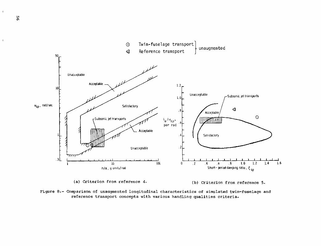
una ugme n t e d I 0 Twin-fuselage transport Q Reference transport
I , I , , , , , I I I I I , , ,
1 lG 100 n/o , g u n i l s l rad
Unacceptable ,-Subsonic jel transports
. 2 . 4 .6 . 8 1.0 1.2 1.4 1.6 0 Short- period damping ratio, 5 SP
( a ) Cr i te r ion from reference 4. (b) Cri te r ion from reference 5.
Figure 8.- Comparison of unaugmented longi tudina l c h a r a c t e r i s t i c s of simulated twin-fuselage and reference t ranspor t concepts w i t h various handling q u a l i t i e s c r i t e r i a .

6c, i n .
1 . 6 -
1.2 - 6 , deg/sec -8 -
I I 1 I I I
0 1 2 3 4 5 6 7 8 9 1 0 1 1 Time, sec
(a) Column step input .
6c, i n . 1 - .
0 1 I I I s I
h T i m e o f control release
6 , deg \
'Attitude overshoot 2'
1.
0 1 2 3 4 5 6 7 8 9 1 0 1 1 Time, see
(b) Column pulse input .
Figure 9.- Ind ica t ion of p i t c h response to various column inputs .
57
411

1 I I 1 I 1 I I I J
MTBT: No SAS; y = 0; h = 2090 f t ; landing gear extended; 6f = 5 O o ; V R = 126 knots (constant)
/ 1 . 6 I
--- 1.2
Effective time delay: ;tl = 0.05 sec (level 1 )
Rise time parameter: AX = X 2 - 2 , = 1.58 sec (level 2 )
Transient peak rat io: A 6 / A 6 2 1 = 0 (level 1 )
6 , deg/sec .8
.4 -
0 I I I I I I
0 1 2 3 4 5 6 7 8 9 10 11
Time, sec
F i g u r e IO. - Pitch-rate response t o a column step i n p u t on unaugmented twin-fuselage t r anspor t airplane.
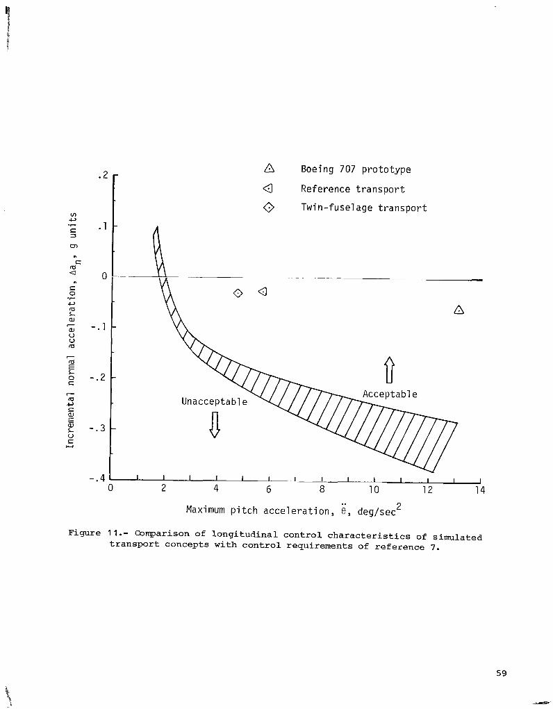
v) c,
S 3
m
*?
n
S a a
S 0
c, a L W
W V V a
la
0 S
n
-7
P
P
E
c la c, S W E W L V S W
::I 0
-.l -
- . 2 -
A Boeing 707 prototype
Q Reference t ransport
0 Twin-fuselage t ransport
c Unacceptable /
- - 3 t Maximum pitch accelerat ion, e , deg/sec 2
Figure 11.- Comparison of longitudinal control characteristics of simulated transport concepts with control requirements of reference 7.

* O L E Z z - 0
1.6
1.2
i, deg/sec .8
.4
0
8 ,
-.4 1 1 1 1 1 1 1
0 2 4 6 8 10 12
Time, sec
Figure 12.- I a t e ra l -d i r ec t iona l response t o a s t e p wheel i npu t on unaugmented twin-fuselage t r a n s p o r t a i rp lane .
60
-. .

tl e
(a) Longitudinal (pitch) control system.
Figure 13.- Normal operational stability and control augmentation system (SCAS). SCAS gains (table VIII) are indicated in parentheses.
I
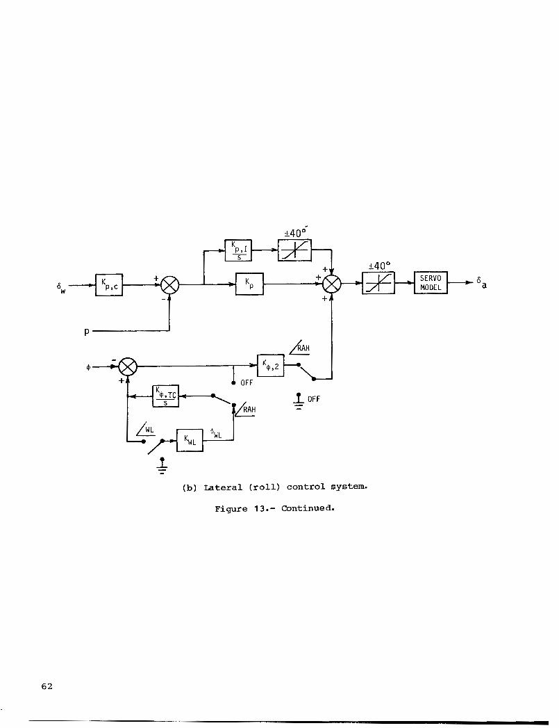
j x K p,I S
Figure 13.- Continued.

+35O @ K @ y R - +
'r,trirn
(c) Direc t iona l (yaw) cont ro l system.
2
Figure 13.- Concluded.
SERVO =-*+ MODEL = 'r
63

(0.51 8) ( 3 . 9 )
V~~~
t (0.14)
APLA
Figure 14.- Block diagram of a u t o t h r o t t l e f o r twin-fuselage configurat ion. Gains are ind ica t ed i n parentheses .
64

6c, in. I I I I I I I I I I
Twin-fuselage with SCAS, tc = 0.65 sec
Twin-fuselage unaugmented, tc = 1.30 sec
Reference airplane ni th SAS, tc = 1.10 sec
1 I I I I I
0 1 2 3 4 5 6 7 8 9 10 11
Time, sec
Figure 15.- Comparison of pi tch-rate response f o r unaugmented and augmented twin-fuselage configurations and reference (augmented) t r anspor t a i rp lane .

1 I I I I I I I I I I , , I ,
10 100 .3L I
1 n / o . g u n i l s l r a d
(a ) Short-period frequency c r i t e r i o n of reference 4.
Twin-fuselage transport Unaugmented 0 Augmented 0 Augmented 4 Reference transport
Unacceptable ,-Subsonic jet transports
. 2 . 4 .6 . 8 1.0 1.2 1.4 1.6 0 Short- period damping ratio, 5
SP
(b) Longitudinal handling q u a l i t i e s c r i t e r i o n of reference 5.
Figure 16.- Comparison of unaugmented and augmented twin-fuselage configurat ions and reference a i rp l ane (augmented) with short-period c r i t e r i a of references 4 and 5.

3.5
3.0
2.5
2.0
1.5
1 .0
.5
0
Twi n-fusel age transport
Ref e rence t r a n sport
--- I Unaugmented
Augmented
Augmented - - _ _ _ _ -
0 1 2 3 4 5 6 7 8 9 10
Time, sec
Figure 17.- Low-speed pi tch-rate response c r i t e r i o n of reference 8. Boundaries f o r normal operation ( P R 6 3 . 5 ) .

J
1 1 1 1 1 1 1 1 1 1
tic, i n .
1 . 6
1 . 2
8 , deg/sec .8
.4
0
/ A e l = 0*234
1 1 Effective time delay: X I = 0.10 sec (level 1 )
Rise time parameter: A X = X 2 - Z1 = 0.88 Sec (leve
Transient peak ra t io : ~6 /ne = 0.128 (level 1 ) 2 1
0 1' 2 3 4 5 6 7 8 9 10 11
Time, sec
Figure 18.- Pitch-rate response to column step input on augmented twin-fuselage transport. (Criteria from ref. 6.)

i Y deglsec
Twin-fuselage t r a n s p o r t
Reference t r a n s p o r t
I Unaugmented
Augmented - - - Augmented - - - - - - -
I 6 i f
0
I
6 -
4
0 2L 0 2 I I I 1 4 6 a 10
4
B , deg
2
0
-4 0 2 4 6 a 10
Time, sec Time, sec
Figure 19.- l a t e ra l -d i r ec t iona l response t o a s tep wheel input on unaugmented and augmented twin-fuselage airplane and reference airplane (augmented).

25
20
15
6r ' B , 9 ,
deg 1c
5 1 0
Latera \ control 1 imi t
\ Percent l a t e r a l control required
0 5 10 15 20 25 30
Steady 90' crosswind veloci ty , knots
00
30
60 Lateral control
avai l ab1 e , percent
40
20
0
Figure 20.- lndicat ion of crosswind t r i m capab i l i t y of simulated twin-fuselage t ranspor t .

Unacceptable
- -.
D Acceptable
-
Sat i s f a c t o r y
1 I 1 I - - 1 - 1 1
0 5 10 15 20 25 30
Steady 90' crosswind v e l o c i t y , knots
Figure 21.- Indica t ion of p i l o t s ' a b i l i t y t o sa fe ly land i n 90° crosswinds. % = 0.5; 6, = S O 0 ; VR = 126 knots .
7 1

I I I I I I1 I ll11111111lIl I I I I I ll1l1l1l1l11l11l111l11l1l11l1l1l1l1l1111l11~l111l1l11l1l1111
6
5
4
Pi lo t rating 3
2
1
0
Satisfactory landing character is t ics Straight- i n approach Ceiling unlimited Calm a i r
I I I 1 I 1 I I I
0 1 2 3 4 5 6 7 8
Time required t o bank 30°, t+=309 sec
Figure 22.- Ind ica t ion of average p i l o t r a t i n g s ass igned t o augmented t w i n - fuse lage concept f o r var ious fuse lage loca t ions a long t h e wing span with bas i c a i l e rons .

Open symbols - l a n d i n g c o n f i g u r a t i o n and speed, and v a r i o u s l a n d i n g t a s k s S o l i d symbols - approach c o n f i g u r a t i o n and speed, and v a r i o u s a i r w o r k tasks
7
6
5
P i l o t r a t i n g 4
3
2
1
Unacceptable
D I I I
Un sa t i s f a c t o r y 8
D 8 / ’
. # ‘ D D D 8
p\ p\ W v v
D D D
8 D Sa t i s f a c t o ry
8
Figure 23.- Summary of r o l l performance from var ious approach and landing t a s k s simulated.
73

60
40
n
+) 20- cc
aJ u != fa c,
-0
fa L aJ c,
2 0 - 7 2 0 -
4
r
Y
f 2 0 f o o t p r i n t 6 -
A 0 (5
/i10 f o o t p r i n t
* I A 4
- @ - - - - -4- - - - -4- -*- I 0 l
0 1 * 0 0 6
-0- - 1 To-
h I A
8 0 d I ’ : S)o I I
0 I 4 & I # b
YQ a+ A h B I . ”
I v, w d f i id A
4 1
cb L - _ _ _ _ _ _ _ _ _ _ _ _ - _ _ _ _ _ J 6 d p II
L- a
;I 60
Wind cond i t ion Unprimed symbols 0
I 16-knot shea r Primed symbols I / 15- knot s t eady crosswind
L I I I I I I I I I I 1
0 200 400 600 800 1000 1200 1400 1600 1800 2000 2200 Longitudinal d i s t a n c e , f t
Figure 24.- Lateral and longi tudina l d i spers ion of touchdown points . (Zero index on t h e longi tudina l scale i s t h e po in t a t which t h e g l i d e s lope i n t e r c e p t s t h e runway.)

Curves represent fa i r ing of d a t a using l inear regression
.04
Ride quality c r i te r ion ( r e f . l l ) ,
Solid symbols represent - accelerations measured
ban)rms 9
g units
Figure 25.- Acceleration responses during landing approaches i n var ious l e v e l s of turbulence. where noted. )
(Accelerat ions measured a t a i r c r a f t cen te r of g rav i ty except
75

'b 0 .5 0 A 1: } Increased rol l control 0 .2
Open symbols represent landing task i n crosswinds or shear w i t h 300-ft ce
Solid symbols represent landing task i n heavy turbulence w i t h 300-ft cei l and -200-ft o f f s e t from runway centerline
and no of fse t from runway centerline v)
-r S
rn . 0 3 r
c,
3
n
l ing
ng
In E
CI
h 5
n u . ~ ~ - S using l inear regression
Curve represents fa i r ing of data (open symbols)
0
c, rd L a,
0 u rd
-7
2 .Ol-
Suggested acceptable r ide qua l i t i es boundaries ?
2 1 0 .01 .02 .03 .04 .05 .06 .07 .08 .09 .IO . l l
Vertical acceleration, (Aan)rmS, g units
Figure 26.- Acceleration responses, measured a t p i l o t s t a t i o n , during landing t a s k on var ious twin- fuse lage configurations.

p, deg/sec 1
0 - - - - - - - - - - - _ - _ _ _ _ _ _ _ - - - - - - P S - C9 2:
-1
0 2 4 6 8 10 0 2 4 6 8 10
Time, sec Time, sec
Figure 27.- Calculated l a t e r a l and normal accelerat ion response t o a wheel s t ep input. vb = 0.5; VR = 126 knots; 6, = 500 ; SCAS operative.

l o o t Engine f a i l e d
-200 L
20 r
I I I I I I I I
0 10 20 30 40 50 60 70 80 -20 I
Time, sec
Figure 28.- Indication of l a t e ra l and v e r t i c a l excursions experienced following f a i l u r e of number 1 engine.

I
Unacceptable A
Unsa t i s f ac t o r y 0
SCAS Auto t h r o t t 1 e
O f f
On
On
0 Of f
0 O f f
El On 0
S a t i s f a c t o r y
S t a t i c margin S t a t i c margin .05C -.16C
I I , I I
40 45 50 3u 35 1 l !
25
Center -o f -g rav i ty , percent c
Figure 29.- Indication of e f f e c t of center-of-gravity locat ion on p i l o t ra t ing . ( P i l o t r a t ings apply t o p i t ch a x i s only i n c a l m atmospheric conditions. evaluation t a s k . )
Glide s lope o f f s e t s w e r e used f o r
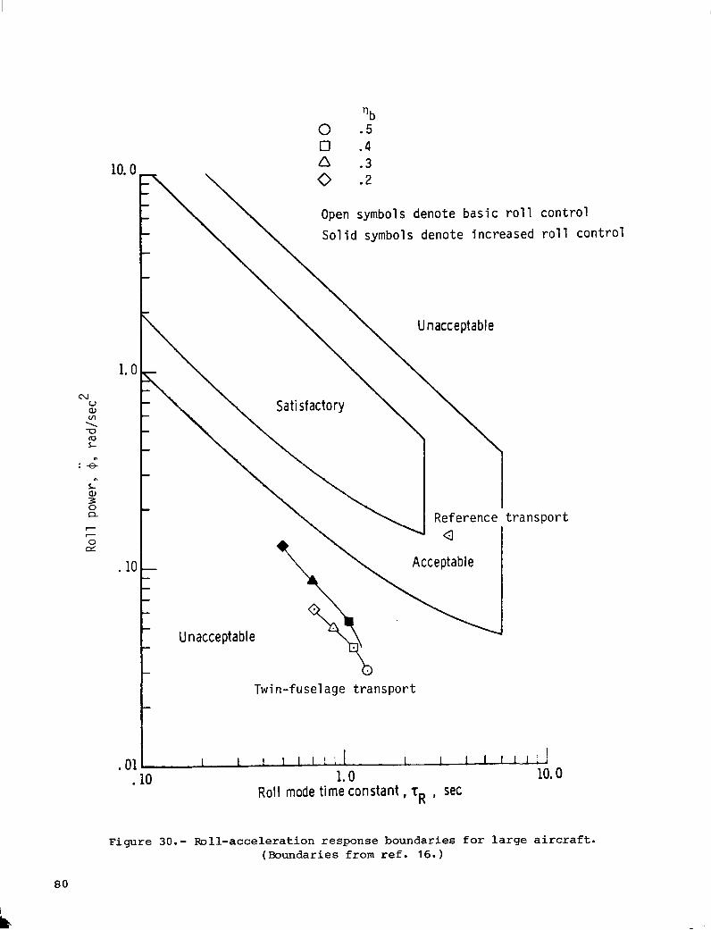
‘b 0 - 5 0 .4 A . 3 10.0
1.0
. 10
Open symbols d e n o t e b a s i c r o l l c o n t r o l S o l i d symbols d e n o t e i n c r e a s e d r o l l con \
\ Satisfactory \ \
t r a n s p o r t
Twin-fusel a g e t r a n s p o r t I
I I I l I I ! I 1 I I I I l l ! ! -
10.0 .01 .10 1.0
Roll mode t ime constant, T~ , sec
Figure 30.- Roll-accelerat ion response boundaries f o r l a r g e a i r c r a f t . (Boundaries from r e f . 16. )
t r o l

70 F
L
- w
60
$ \ \ \ \ \ \ \ \ % 50
? CT aJ U
b
Twi n-fusel age transport , I 1 1 1 1 I I I 1 I I 1 I I I I I I I 1
- 40 0 ' 8 .
2 20
10
'b 0 .5 0 . 4 n . 3 0 .2
Open symbols denote basic rol l control Sol i d symbols denote increased rol l control
Figure 31.- Ib11-rate capability criterion for transport aircraft. (Boundaries from ref. 17.)

O b 0 .5
Unacceptable 0 .4 0 A .3
0 - 2 S o l i d symbols denote no SCAS
A// //. A- / //
I 1 J
0 -40 -80 -120 -160 -200 -240 -280 -320 -360 deg
( a ) Basic r o l l cont ro l .
Unacceptable 0
0 -40 -80 -120 -160 -200 -240 -280 -320 -360 $6, deg
(b) Increased r o l l cont ro l .
Figure 32.- Bank-angle o s c i l l a t i o n l i m i t a t i o n s of re ference 16. F ina l approach; VR = 126 knots ; 6, = 50°; SCAS on.
82
... . .. .... . . , . .. .- -

'b 0 .5 0 .4 Unacceptable
0 - 2
0 Reference Acceptable
t r a n s po r t POSC'P," -4
S a t i s f a c t o r y L%%-_ ///
/
L.-L. -3 I - 0 . . -_I I
0 -40 -80 -120 -160 -200 -240 -280 -320 -360
ig, deg
( a ) -sic roll cont ro l .
Unacceptable e
.6 -
POSC/P," - 4 -
.2 -
L I 1
0 -40 -80 -120 -160 -200 -240 -280 -320 -360
$@, deg
(b) Increased r o l l con t ro l .
Figure 33. - Roll-rate o s c i l l a t i o n l i m i t a t i o n s of re ference 16. Final approach; VR = 126 knots; 6, = 50°; SCAS on.
a 3

Flagged symbols based on ach ieved r o l l i n 2.5 sec. Unf lagged symbols based on ach ieved r o l l i n 3.2 sec.
S a t i s f a c t o r y , f u l l c o n t r o l
15
10
ABmax/ K, deg
5 -
/ / A 0// - - 0 .4
0 - 2
A .3 Q Acceptab le
S a t i s f a c t o r y
,-/ // .- -- -
- (3 Reference
I I 1 J
( a ) Basic r o l l cont ro l .
Unacceptable 15
10
K, d e g
5
Acceptab le n %
0: -L' 0 -40 -80 -120 -160 -200 -240 -280 -320 -360
qB3 deg
(b) Increased r o l l con t ro l .
Figure 34.- S i d e s l i p excursion l imi t a t ions of re ference 16. F ina l approach; VI = 126 knots; 6, = 500; SCAS on.
84

1 . Report No. 2. Government Accewion No.
_ _ NASA TP-2183
SIMULATOR STUDY O F FLIGHT CHARACTERISTICS O F A LARGE TWIN-FUSELAGE CARGO TRANSPORT AIRPLANE DURING APPROACH AND LANDING
-_ -~ - -_ - 4. Title and Subtitle
. - ... ~ . . ~. .
7. Author(s)
W i l l i a m D. Grantham, Perry L. Deal, Gerald L. Keyser, Jr., and Paul M. Smith
. . - -. . -. . . . - . - - - . _ _ - .- - .
9. Performing Organization Name and Address
NASA Langley Research Center Hampton, VA 23665
- . .. . . . .~. . ~
Agency Name and Address
National Aeronautics and Space Administration Washington, DC 20546
. .- ~.
3. Recipient's Catalog No.
-.
5. Report Date November 1983
6. Performing Organization Code 505-34-03-03
- 8. Performing Organization Report No
L- 15505
10. Work Unit No.
. _ _ 1 1 . Contract or Grant No.
13. Type of Report and Period Covered
Technical Paper
14. Sponsoring Agency Code . . -
~ -___. ..
15. Supplementary Notes
W i l l i a m D. Grantham and Perry L. Deal: Langley Research Center, Hampton, Virginia. Major Gerald L. Keyser, Jr.: Air Force Systems Command Liaison Office, Langley
Paul M. Smith: Kentron Internat ional , Inc. , Hampton, Virginia.
A six-degree-of-f reedom, ground-based simulator study has been condacted t o evaluate the low-speed f l i g h t charac te r i s t ics of a twin-fuselage cargo transport a i rplane and t o compare these charac te r i s t ics with those of a large, single-fuselage (reference) t ransport configuration which w a s s imilar t o the Uckheed C-5C airplane. Tne primary p i lo t ing task w a s t he approach and landing. The r e s u l t s of t h i s study indicated t h a t i n order t o achieve "acceptable" low-speed handling q u a l i t i e s on the twin-fuselage concept, considerable s t a b i l i t y and control augmentation w a s required, and although the augmented airplane could be landed safe ly under adverse conditions, the r o l l performance of the a i r c r a f t had t o be improved appreciably before the handling qua l i t i e s w e r e r a ted as being "satisfactory." These ground-based simulation r e s u l t s indicated t h a t a value of (time required t o bank 30°) l e s s than 6 sec should r e s u l t i n "acceptable" r o l l response charac te r i s t ics , and when i s less than 3.8 sec, "satisfactory" r o l l response should be a t ta inable on such large and unusually configured a i r c r a f t as the subject twin-fuselage cargo t ransport concept.
R e s e a r ch C e n t e r , Hamp t on, V i r g i n i a.
I ~ _ _ . - - - . - . -- -. .. - --
16. Abstract
t4=30 t+=30
-_ .. . . - __ - . . ~ - - ~. . . . . .
17. Key Words (Suggested by Authoris)) I 18. Distribution Statement
Large t ransports Unusually configured a i r c r a f t Handling q u a l i t i e s Ride qua l i t i e s
Unclassified - Unlimited
Subject Category 0 8 . - . - I Approach and landing
19. Security Classif. (of this report) - - - - . - . 1 20. Security Classif. (of this page) 1 21. No. of Pages 1 22. Rice ~
.
Unc l a s s i f i e d Unclassified - -
For sale by the Natlonal Technical lnformatlon Service, Sprinefleld, Vlrglnia 22161 NASA-Lanql ey, 1983

- - .-- , . .
National Aeronautics and Space Administration
Washington, D.C. 20546 Official Business
Penalty for Private Use, $300
THIRD-CLASS BULK RATE Postage and Fees Paid National Aeronautics and Space Administration NASA451
POSTMASTER: If Undeliverable (Section 158 Postal Manual) Do Not Return