Large Quantity Heat Storage for Solar Thermal Power Plant
25
Peiwen (Perry) Li Department of Aerospace and Mechanical Engineering The University of Arizona Tel: 520-626-7789 Fax: 520-621-8191 http://www.ame.arizona.edu/faculty/li/li.php Oct. 23, 2009 Large Quantity Heat Storage for Solar Thermal Power Plant
Transcript of Large Quantity Heat Storage for Solar Thermal Power Plant

Peiwen (Perry) Li
Department of Aerospace and Mechanical EngineeringThe University of Arizona
Tel: 520-626-7789Fax: 520-621-8191
http://www.ame.arizona.edu/faculty/li/li.phpOct. 23, 2009
Large Quantity Heat Storage for Solar Thermal Power Plant

Acknowledgement
Sponsors: DOE US Solar Holdings LLCArizona public Service (APS)
Team members:Faculty: Peiwen Li, Cho Lik Chan, Larry SobelStudents: Jon Van Lew, Wafaa Karaki, P. V. Phanidhar

• Some Data about Renewable Energy
• Importance of Energy Storage
• Heat Storage
Outline of the Presentation
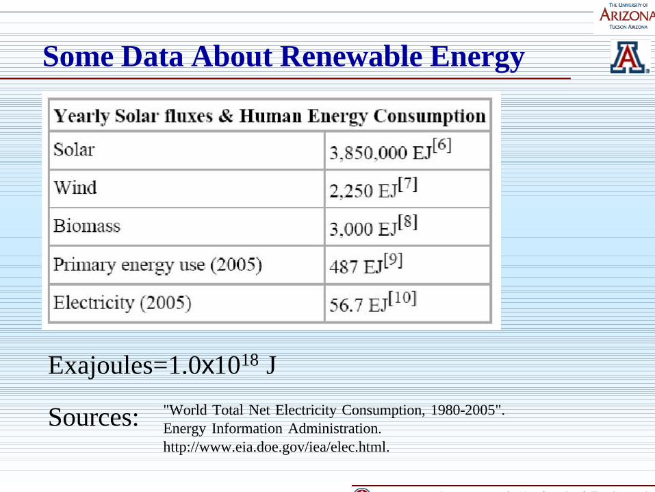
Some Data About Renewable Energy
Exajoules=1.0x10¹⁸ J
Sources: "World Total Net Electricity Consumption, 1980-2005".Energy Information Administration.http://www.eia.doe.gov/iea/elec.html.
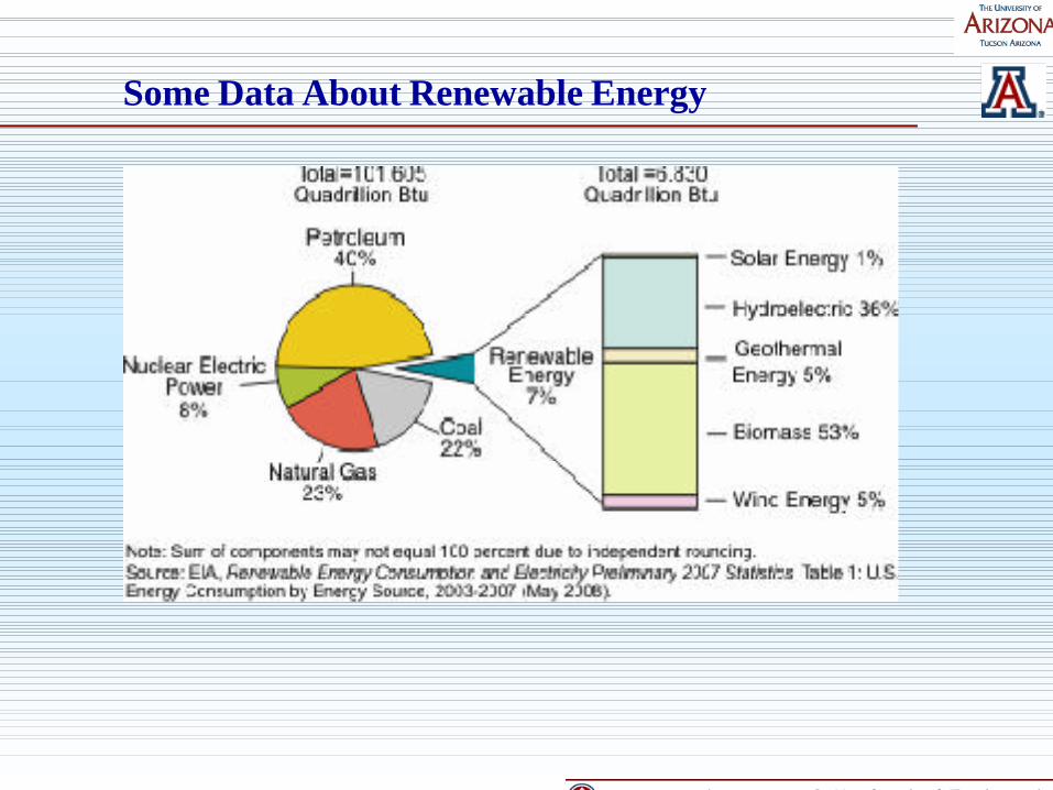
Some Data About Renewable Energy

Importance of Energy Storage
Challenging Issues in Renewable Energy:High costNot always availableif no storage
Solution:Low the costStore energy

Large Quantity of Energy Storage
Biofuel, chemical fuel production and storage
Source: www.treehugger.com/aglae-biofuels
Very long term (Years)large quantity possible

Daily-monthly-term large quantity storage
• Heat storage ( reliable technology )
• Pump water to reservoir (location limitation)
• Compressed air ( low round-trip efficiency)

Solar Thermal Storage
Sensible heatHeat transfer fluid (HF) direct storage 400oC~500oCHF plus heat storage material
HF---Molten salts and synthetic oil
Latent heat in phase change (small volume, but)HF plus storage materialNeed low cost material with melting point ~550oC

Sensible heat storage
Heat transfer fluid (HF) direct storage 400oC ~500oC
Ideal scenario:
Heat transfer fluid is stored in and taken outat the same temperature (no exergy loss)
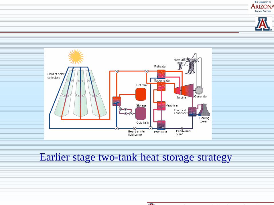
Earlier stage two-tank heat storage strategy

Up and down movable thermal insulation baffle
Cold fluid
Hot fluid
Single tank thermocline heat transfer fluid heat storageCost cut is significant due to less use of HF.( adding an insulation baffle makes ideal storage)

Up and down movable thermal insulation baffle
Cold fluid
Hot fluid
Filler material Void fraction ε
t (hour)
Th Tout (
oC)
tfull
Tl
Th
Tout (oC)
tfull ( ε tfull)
Tl Tcut-off
t (hour)
full
Th
Tout (oC)
tfull ( ε tfull)
Tl Tcut-off
t (hour)
Further cost cut using solid filler material
Discharge process (exit fluid temperature at top)

t (hour)
Th Tout (
oC)
tfull
Tl
Texit
Hot fluid charges from top(fluid exit temperature at the bottom is monitored)
t (hour)
Th Tout (
oC)
tfull ( ε tfull)
Tl
Tcut-off Texit
Up and down movable thermal insulation baffle
Cold fluid
Hot fluid
Filler material Void fraction ε

Advantage of using cheap filler material:--cost cut.
Disadvantage of using filler material:--it is impossible to run the same period of time for
charging/discharging without temperature degradationin discharging.
Choices:• Run at longer charging time. How much longer?• Run at larger changing flow rate. How much larger?

dz
2R
H
z
t
TRCTThS
z
TUCR f
fffrrf
ff ∂
∂=−+
∂
∂− 22 )( επρεπρ
tT
RCTThS rrrfrr ∂
∂−−=− 2)1()( περ
Energy balance and heat transfer governing equations

Assuming that the first charge takes sufficiently long time and fully charged.
The discharge will deliver fluid with temperature variation shown bellow:
Discharge
Top Z*=1
Bottom Z*=0

A new charge from top pushesfluid flow out of the bottom
A new discharge pushes fluidout of the top of the tank
Temperature of fluid at bottomz*=1
Charge
Top Z*=0
Bottom Z*=1
Discharge
Top Z*=1
Bottom Z*=0
Temperature of fluid at topz*=1
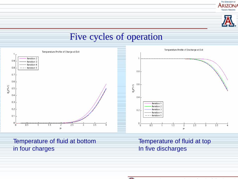
Temperature of fluid at bottomin four charges
Temperature of fluid at topIn five discharges
Five cycles of operation

Charging end profile (bottom T rises )
Temperature along the tank length in a charge process.High temperature fluid is pumped in from Z=0.0 (top).A heat wave is moving to the direction of z=1.0 (bottom).
Charge
Top Z*=0
Bottom Z*=1
Dimensionless temperature
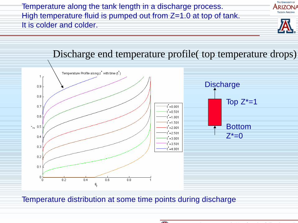
Temperature along the tank length in a discharge process.High temperature fluid is pumped out from Z=1.0 at top of tank.It is colder and colder.
Discharge
Top Z*=1
Bottom Z*=0
Temperature distribution at some time points during discharge
Discharge end temperature profile( top temperature drops)
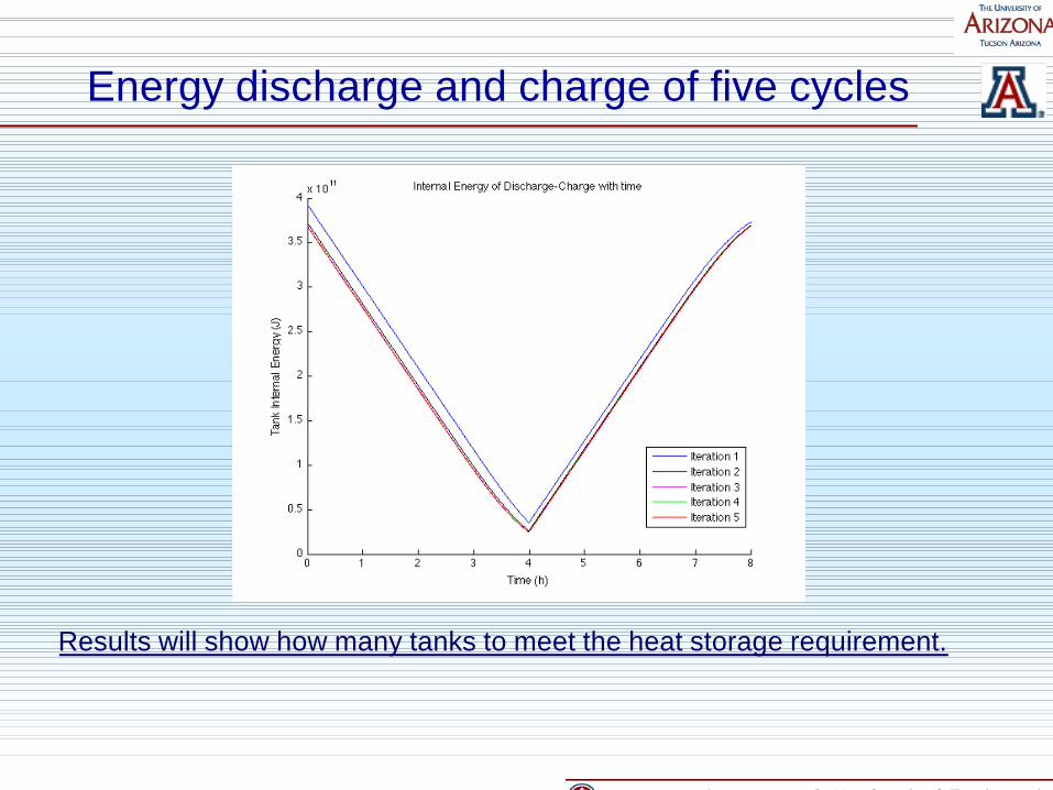
Energy discharge and charge of five cycles
Results will show how many tanks to meet the heat storage requirement.

Temperature profile and number of tanksFor example, charging 5 hours and discharge 4 hours

Energy storage performance and void fraction relationship

1. Using filler is the latest version of heatstorage technology. It is cost effective and efficient.
2. A longer charging period than discharging is neededif filler material is used.
3. Theoretical model has been developed to size thestorage volumes and predict the temperature profilesof charging and discharging process so to provideneeded information for extended power plantoperation.
Conclusions