LARGE DEFORMATION FINITE ELEMENT ANALYSIS …Large deformation finite element analysis of undrained...
10
Studia Geotechnica et Mechanica, Vol. 38, No. 1, 2016 DOI: 10.1515/sgem-2016-0005 LARGE DEFORMATION FINITE ELEMENT ANALYSIS OF UNDRAINED PILE INSTALLATION JAKUB KONKOL, LECH BAŁACHOWSKI Department of Geotechnics, Geology and Marine Civil Engineering, Faculty of Civil and Environmental Engineering, Gdańsk University of Technology (GUT), Gdańsk, Poland, e-mail: [email protected], [email protected] Abstract: In this paper, a numerical undrained analysis of pile jacking into the subsoil using Abaqus software suit has been pre- sented. Two different approaches, including traditional Finite Element Method (FEM) and Arbitrary Lagrangian–Eulerian (ALE) formulation, were tested. In the first method, the soil was modelled as a two-phase medium and effective stress analysis was per- formed. In the second one (ALE), a single-phase medium was assumed and total stress analysis was carried out. The fitting between effective stress parameters and total stress parameters has been presented and both solutions have been compared. The results, dis- cussion and verification of numerical analyzes have been introduced. Possible applications and limitations of large deformation modelling techniques have been explained. Key words: Abaqus, Arbitrary Lagrangian–Eulerian, ALE, FEM, Pile jacking, Pile installation, Undrained analysis 1. INTRODUCTION In the last few years, a rapid development of IT branch has opened up a new range of possibilities in geotechnical numerical modelling. Although the ma- jor part of methods and theory has been established in the last decades, the effective application of its capa- bilities becomes possible nowadays. Arbitrary La- grangian–Eulerian (ALE) method (Donea et al., 2004) as well as Coupled Eulerian–Lagrangian (CEL) method (Noh, 1963) have been developed especially for large deformation problems and have found a practical ap- plication in modelling pile penetration problems. The main research area is related to the pile set-up in sands (e.g., Hamann et. al., 2015). Numerical modelling of penetration problems in clays is usually linked to off- shore structures (e.g., Tho et al., 2013). Installation effects due to the pile set-up are in in- terest of geotechnical engineers since the early 1950s (e.g., Cummings et al., 1950). The main reason for that is to use the pile capacity increase due to installa- tion in design. For clayey soils the pile capacity in- crease is related to the changes in stress state during installation and following consolidation phase. The ageing effects in cohesive soils play minor role (Ko- murka et al., 2003). The basic problem in numerical modelling of such phenomenon is naturally related with large deformations of the soil structure and at the pile–soil interface. Consequently, the application of the traditional finite element method (FEM) could be troublesome because of mesh distortions. Numerical methods for large deformation problems such as ALE or CEL are developed in frames of explicit formula- tion, which gives the best effectiveness. The consoli- dation process cannot be modelled in explicit formu- lation. However, it is easy to obtain with implicit formulation. Different nature of installation and con- solidation processes causes extremely small amount of published FEM studies. Some strategies have been developed to solve that problem. The first one is to use both solvers. In that proposition explicit calcula- tions are made for installation phase. Then, the entire solution is mapped by an external algorithm to the new mesh and the problem is calculated by implicit solver. This kind of analysis was done by Yi et al. (2014). Modelling pile installation and consolidation directly by implicit solver is possible, but requires special care. Such analyses were done by Zhou et al. (2013) for clayey soil and by Hamann et al. (2015) for sands. In this paper, the possibility of pile undrained in- stallation using an implicit solver is presented. A two- phase soil model is used and calculations are per- formed in accordance with effective stress approach. The accuracy of the effective stress solution is con- trolled by independent calculation in the total stress analysis with ALE method, where explicit solver is used. Finally, the interpretation of the results with
Transcript of LARGE DEFORMATION FINITE ELEMENT ANALYSIS …Large deformation finite element analysis of undrained...

Studia Geotechnica et Mechanica, Vol. 38, No. 1, 2016DOI: 10.1515/sgem-2016-0005
LARGE DEFORMATION FINITE ELEMENT ANALYSISOF UNDRAINED PILE INSTALLATION
JAKUB KONKOL, LECH BAŁACHOWSKI
Department of Geotechnics, Geology and Marine Civil Engineering, Faculty of Civil and Environmental Engineering,Gdańsk University of Technology (GUT), Gdańsk, Poland, e-mail: [email protected], [email protected]
Abstract: In this paper, a numerical undrained analysis of pile jacking into the subsoil using Abaqus software suit has been pre-sented. Two different approaches, including traditional Finite Element Method (FEM) and Arbitrary Lagrangian–Eulerian (ALE)formulation, were tested. In the first method, the soil was modelled as a two-phase medium and effective stress analysis was per-formed. In the second one (ALE), a single-phase medium was assumed and total stress analysis was carried out. The fitting betweeneffective stress parameters and total stress parameters has been presented and both solutions have been compared. The results, dis-cussion and verification of numerical analyzes have been introduced. Possible applications and limitations of large deformationmodelling techniques have been explained.
Key words: Abaqus, Arbitrary Lagrangian–Eulerian, ALE, FEM, Pile jacking, Pile installation, Undrained analysis
1. INTRODUCTION
In the last few years, a rapid development of ITbranch has opened up a new range of possibilities ingeotechnical numerical modelling. Although the ma-jor part of methods and theory has been established inthe last decades, the effective application of its capa-bilities becomes possible nowadays. Arbitrary La-grangian–Eulerian (ALE) method (Donea et al., 2004)as well as Coupled Eulerian–Lagrangian (CEL) method(Noh, 1963) have been developed especially for largedeformation problems and have found a practical ap-plication in modelling pile penetration problems. Themain research area is related to the pile set-up in sands(e.g., Hamann et. al., 2015). Numerical modelling ofpenetration problems in clays is usually linked to off-shore structures (e.g., Tho et al., 2013).
Installation effects due to the pile set-up are in in-terest of geotechnical engineers since the early 1950s(e.g., Cummings et al., 1950). The main reason forthat is to use the pile capacity increase due to installa-tion in design. For clayey soils the pile capacity in-crease is related to the changes in stress state duringinstallation and following consolidation phase. Theageing effects in cohesive soils play minor role (Ko-murka et al., 2003). The basic problem in numericalmodelling of such phenomenon is naturally relatedwith large deformations of the soil structure and at the
pile–soil interface. Consequently, the application ofthe traditional finite element method (FEM) could betroublesome because of mesh distortions. Numericalmethods for large deformation problems such as ALEor CEL are developed in frames of explicit formula-tion, which gives the best effectiveness. The consoli-dation process cannot be modelled in explicit formu-lation. However, it is easy to obtain with implicitformulation. Different nature of installation and con-solidation processes causes extremely small amount ofpublished FEM studies. Some strategies have beendeveloped to solve that problem. The first one is touse both solvers. In that proposition explicit calcula-tions are made for installation phase. Then, the entiresolution is mapped by an external algorithm to the newmesh and the problem is calculated by implicit solver.This kind of analysis was done by Yi et al. (2014).Modelling pile installation and consolidation directlyby implicit solver is possible, but requires special care.Such analyses were done by Zhou et al. (2013) forclayey soil and by Hamann et al. (2015) for sands.
In this paper, the possibility of pile undrained in-stallation using an implicit solver is presented. A two-phase soil model is used and calculations are per-formed in accordance with effective stress approach.The accuracy of the effective stress solution is con-trolled by independent calculation in the total stressanalysis with ALE method, where explicit solver isused. Finally, the interpretation of the results with

J. KONKOL, L. BAŁACHOWSKI46
further possibilities of this modelling technique isdiscussed.
2. PROPOSED MODELLING TECHNIQUEFOR THE PILE UNDRAINED
INSTALLATION
2.1. IMPLICITVERSUS EXPLICIT ANALYSIS
The modelling technique presented in this paperconsists of two branches. The first one is the total stressanalysis using ALE method and explicit solver. Thesecond one is the effective stress approach, where thesoil is modelled as two-phase medium and the implicitsolver is used. The difference between explicit andimplicit methods lies in the mathematical formulationof the problem. Let us assume the current configurationof the system Y(t + Δt) at time t + Δt and the previousconfiguration of the system Y(t) at time t, as is shownin Fig. 1. The explicit methods calculate the state ofthe system at time t + Δt from state of the system attime t, which can be written by the equation
))(()( tYFttY =Δ+ . (1)
Fig. 1. Configurations of the system at two different times(e.g., during deformation of the body)
The implicit methods use different strategy. Thestate of the system Y(t + Δt) is calculated from bothstates, at times t and t + Δt, respectively. This can bewritten as follows
0))(),(( =Δ+ ttYtYF . (2)
Here, the basic advantages and disadvantages ofboth methods appear. The explicit method, as it isimplemented in Abaqus, uses the central-differenceintegration rule and very small time steps defined as(Dassault Systémes, 2013)
d
e
cl
t min,≈Δ (3)
where Δt – time increment [s], cd – dilatational wavespeed [m/s], le,min – smallest element dimension in themesh [m].
The features of the explicit method are very at-tractive and allow the large jobs to be modelled withmuch smaller amount of physical memory than it isrequired in the implicit formulation. Large processingpower is needed instead. Explicit method is suitablefor modelling quasi-static and dynamic events, whileimplicit method is perfect for calculating the staticresponse of the system.
2.2. ARBITRARYLAGRANGIAN-EULERIAN METHOD
Arbitrary Lagrangian-Eulerian method combinesbest features of Eulerian and Lagrangian formulations(Donea et al., 2004). Both soil and pile are discretizedwith the Lagrangian mesh. ALE description consistsof three domains – the material, the spatial and thereferential one. This assumption allows an arbitrarymovement to be introduced between material pointsand the spatial (nodes) mesh. As a result, three stepsof ALE description during single time increment canbe specified. In the first step, the material nodes aremoved to the new positions. Then, in the rezone step,a new spatial mesh is built for the best matching to thematerial nodes. Finally, the solution is transferredfrom the old mesh to the new one. As can be noticed,the crucial aspect in ALE formulation is the accuracyof remeshing algorithm. However, this method re-quires the same material properties in all ALE do-mains. Consequently, the same undrained shearstrength of the soil as well as elastic parameters needto be used. This problem was reported by Bienen et al.(2015) and was also experienced by the authors in thisparticular study.
2.3. COUPLED PORE FLUID DIFFUSIONAND STRESS ANALYSIS BY FEM
The coupled pore fluid diffusion and stress analy-sis enables us to consider the soil as a two-phase me-dium. This kind of modelling is especially dedicatedto consolidation problems, but it can also be success-fully used in undrained analysis. The framework ofthis formulation consists of porous elastic modelcombined with cap plasticity model. The coupled porefluid diffusion and stress analysis is not intended tomodel the large deformation problems because ofmesh distortion that may occur. The accuracy of the

Large deformation finite element analysis of undrained pile installation 47
solution is controlled by the allowable pore fluid pres-sure in each time increment. The complementary cri-terion is the minimum useable time increment Δt. Thisvalue can be estimated by Vermeer and Verruijt(1981) formula for one dimensional consolidationproblem
kE
lt ew
⋅⋅
⋅≥Δ
6
)( 2γ(4)
where γw – unit weight of water [kN/m3], le – elementlength [m], E – elastic modulus [kPa], k – coefficientof permeability [m/s].
Choosing the appropriate minimum time incre-ment is crucial for the solution without “overshoot”in pore fluid pressure calculation. On the otherhand, equation (4) is derived only for one dimen-sional consolidation problem, but it is also widelyused in three dimensional models (e.g., Dai andQin, 2013).
Summing up, the penetration problems calculatedin terms of the coupled pore fluid diffusion andstress analysis cannot be always possible because ofmodel geometry, mesh distortion or allowable timeincrement. Further, even when such analysis is pos-sible, the obtained results may be false. These are thereasons why ALE method was used to verify coupledpore fluid diffusion and stress analysis in the pileinstallation problem.
2.4. GENERAL CONSIDERATIONABOUT THIS RESEARCH
In this paper, ALE method is considered asa major modelling technique. This implies the useof single-phase uniform material, as was explainedin Section 2.2. To achieve this assumption the Trescamodel with linear elastic parameters was used. Forcoupled pore fluid diffusion and stress analysis theModified Cam-Clay (MCC) model was assumed.The fitting between these two models is presentedin the next section. The minimum usable time in-crement described by equation (4) was calculatedby selecting the mesh size and the coefficient ofpermeability.
Another problem with the coupled pore fluid dif-fusion and stress analysis is the modelling of soil–pileinterface. Preliminary analysis of the pile jacking has
shown that the Coulomb friction model cannot beapplied on the pile toe. Hence, friction model on thepile shaft was assumed, while frictionless behaviouron pile toe was applied. The same interface conditionsin ALE model were used.
3. EFFECTIVE STRESSVERSUS TOTAL STRESS ANALYSIS
In presented modelling technique the effectivestress and total stress analysis will be introduced. Inboth approaches different constitutive models areused. To obtain reliable solutions, some correlationbetween Tresca parameters and MCC parameters hasto be assumed. A relation between the linear elasticmodel and the porous elastic model is also needed.The fitting between the total stress analysis and theeffective stress analysis will be performed in the fol-lowing way. Firstly, the parameters for ALE modelwill be assumed. They are presented in Table 1. Next,the soil parameters required in the effective stressanalysis will match those occurring in ALE model. Toobtain correlation between the undrained and drainedelastic strength parameters the assumption of equalshear modulus will be made. This can be done for thematerials for which the shear and volumetric effectsare decoupled (Atkinson, 2007)
)1(2 u
uu
EGGν+
==′ (5)
where G′ – effective shear modulus [kPa], Gu – un-drained shear modulus [kPa], Eu – undrained elasticmodulus [kPa], νu – undrained Poisson ratio [–].
Hence, the porous elastic medium in effectivestress analysis can be defined by constant shearmodulus G′ and logarithmic elastic modulus κ. Thisdefinition of porous material will be consistent withthe assumption of decoupled shear and volumetriceffects (Dassault Systémes, 2013).
Another problem lies in fitting the undrained shearstrength of soil cu to the MCC plasticity parameters.Some proposition to deal with that issue has been putforward by Potts and Zdravkovic (1999). As differentparameters are used in Potts and Zdravković proposi-tion and in Abaqus formulation, the independent deri-vation of the MCC parameters is made here.
Table 1. Material parameters for ALE model (Linear elastic with Tresca plasticity)
Parameter ρtot [t/m3] Eu [kPa] υu [–] Φu [º] ψ [º] cu [kPa] K0 [–] σt [kPa]Value 2.2 2500 0.49 0 0 80.0 1.0 1.0
J. KONKOL, L. BAŁACHOWSKI48
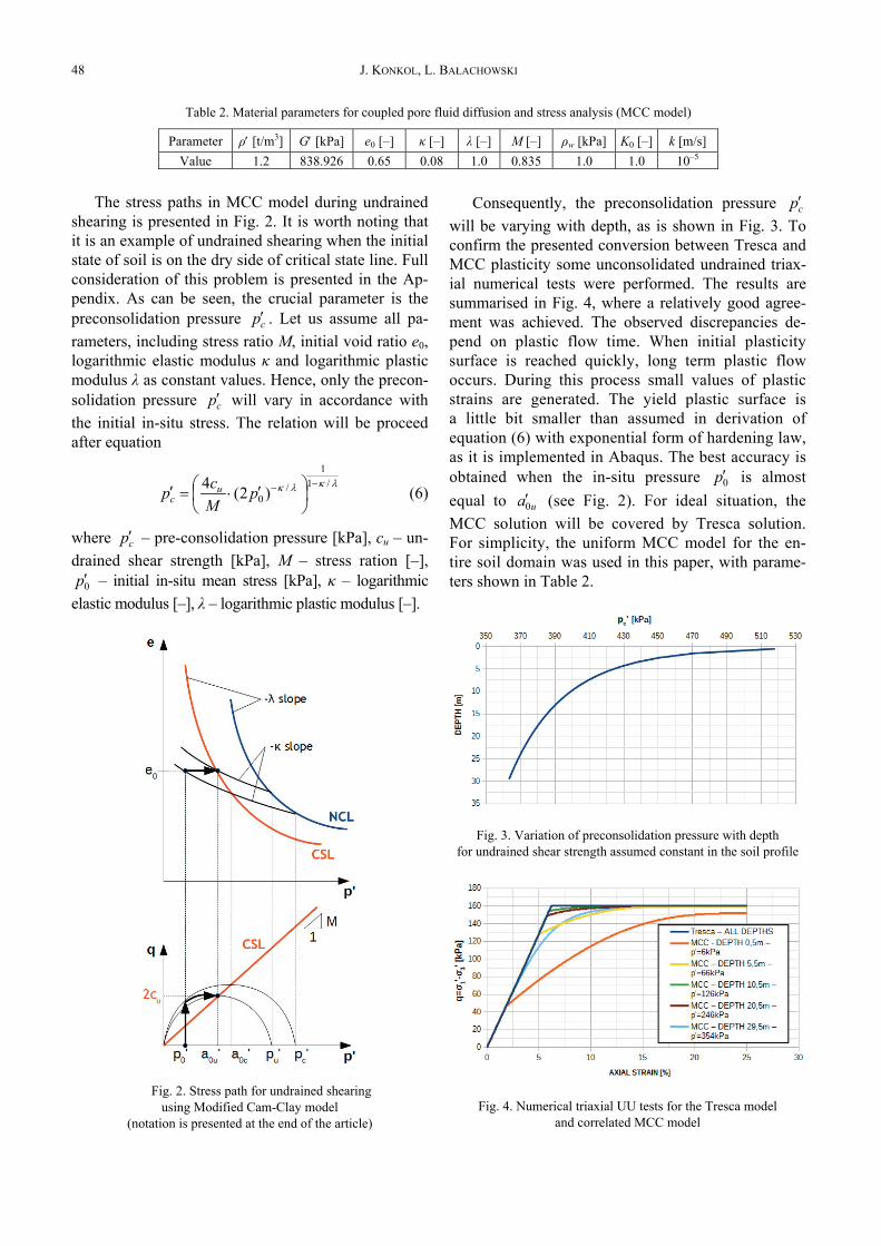
The stress paths in MCC model during undrainedshearing is presented in Fig. 2. It is worth noting thatit is an example of undrained shearing when the initialstate of soil is on the dry side of critical state line. Fullconsideration of this problem is presented in the Ap-pendix. As can be seen, the crucial parameter is thepreconsolidation pressure cp′ . Let us assume all pa-rameters, including stress ratio M, initial void ratio e0,logarithmic elastic modulus κ and logarithmic plasticmodulus λ as constant values. Hence, only the precon-solidation pressure cp′ will vary in accordance withthe initial in-situ stress. The relation will be proceedafter equation
λκλκ /11
/0 )2(4 −− ⎟
⎠⎞
⎜⎝⎛ ′⋅=′ p
Mcp u
c (6)
where cp′ – pre-consolidation pressure [kPa], cu – un-drained shear strength [kPa], M – stress ration [–],
0p′ – initial in-situ mean stress [kPa], κ – logarithmicelastic modulus [–], λ – logarithmic plastic modulus [–].
Fig. 2. Stress path for undrained shearingusing Modified Cam-Clay model
(notation is presented at the end of the article)
Consequently, the preconsolidation pressure cp′will be varying with depth, as is shown in Fig. 3. Toconfirm the presented conversion between Tresca andMCC plasticity some unconsolidated undrained triax-ial numerical tests were performed. The results aresummarised in Fig. 4, where a relatively good agree-ment was achieved. The observed discrepancies de-pend on plastic flow time. When initial plasticitysurface is reached quickly, long term plastic flowoccurs. During this process small values of plasticstrains are generated. The yield plastic surface isa little bit smaller than assumed in derivation ofequation (6) with exponential form of hardening law,as it is implemented in Abaqus. The best accuracy isobtained when the in-situ pressure 0p′ is almostequal to ua0′ (see Fig. 2). For ideal situation, theMCC solution will be covered by Tresca solution.For simplicity, the uniform MCC model for the en-tire soil domain was used in this paper, with parame-ters shown in Table 2.
Fig. 3. Variation of preconsolidation pressure with depthfor undrained shear strength assumed constant in the soil profile
Fig. 4. Numerical triaxial UU tests for the Tresca modeland correlated MCC model
Table 2. Material parameters for coupled pore fluid diffusion and stress analysis (MCC model)
Parameter ρ′ [t/m3] G′ [kPa] e0 [–] κ [–] λ [–] M [–] ρw [kPa] K0 [–] k [m/s]Value 1.2 838.926 0.65 0.08 1.0 0.835 1.0 1.0 10–5

Large deformation finite element analysis of undrained pile installation 49
The earth pressure at rest coefficient was assumedto be equal to 1.0. This is a safe assumption because itgives the uniform distribution of pressure in all di-mensions.
3. DEVELOPINGTHE NUMERICAL MODELS
The geometry of the models was the same in thetwo approaches presented. The models were axisym-metric with dimensions and boundary conditions pre-sented in Fig. 5. The soil was modelled as a deformablebody while the pile was assumed to be a rigid one. Thepile was pre-installed in the soil at a depth of 0.5 m toavoid distortions of finite elements at the beginningof jacking. The process of installation was modelledusing so-called zipper-technique, which was developedby Mabsout and Tassoulas (1994). In this technique,a small diameter tube supports the soil domain, as canbe seen in Fig. 5. During jacking the pile slides after thetube and pushes soil outwards. The tube has diameterof 1 mm and frictionless contact with the soil. Contactbetween the pile shaft and the soil is modelled usingfinite sliding technique and Coulomb friction modelwith coefficient of friction equal to 0.231. Due to nu-merical problems in the coupled pore fluid diffusionand stress analysis the contact between the pile toe andthe soil was assumed to be frictionless, as was men-tioned in section 2.4. The pile was jacking with velocityof 1 cm/s to the depth of 8.0 m.
Fig. 5. Geometry and boundary conditionsfor undrained pile jacking simulation
3.1. ARBITRARYLAGRANGIAN-EULERIAN APPROACH
The numerical model consists of 28803 elementswith minimum element size of 2.5×2.5 cm in the re-fined mesh area. The quadratic, 4 nodded, linear ele-ments with reduced integration were used. Due to thelarge number of increments the analysis was con-ducted with double precision.
3.2. COUPLED PORE FLUID DIFFUSIONAND STRESS APPROACH
The numerical model consists of 210883 elementswith minimum size 1.0×0.5 cm in the refined mesharea. Thirty layers of soil were assumed due to differ-ent preconsolidation pressures. The quadratic, secondorder elements with reduced integration were used.Although, when contact problems are involved, thefirst order elements are better suited, the second orderelements perform better where stress concentrationoccurs (Dassault Systémes, 2013). Here, some com-promise has to be made. As the pile jacking problemis related with large concentrated stresses the secondorder elements have to be used. However, the contactproblem concerns mainly three-dimensional, secondorder elements, so in the axisymmetric model thisissue does not occur. The value of permeability coeffi-cient was assumed as 10–5 m/s, as stated in Table 2.Using equation (4) and effective soil parameters theminimum usable time increment was calculated asvarying from 0.22222 s to 0.00094 s. During the analy-sis the time increments were monitored and settled inthe range from 0.5 s to 0.00195 s, which is higher thanthe estimated interval. Hence, no “overshoot” in thepore fluid pressure calculation is expected.
4. RESULTS AND INTERPRETATION
The most important aspect of the pile jackingis the determination of base resistance (see Fig. 6).A good agreement between the total and the effectivestress analysis is achieved. The rapid increase of toeresistance to the value of 450 kPa is observed justafter start of jacking. Then a slight increase withpenetration depth appears. The averaged unit shaftresistance is plotted in Fig. 7. Here, a good agreementis also obtained. The shaft resistance is mobilizedmore smoothly and it is about 10% of the base resis-tance value.

J. KONKOL, L. BAŁACHOWSKI50
Fig. 6. Pile toe resistance during undrained jacking Fig. 7. Pile shaft resistance during undrained jacking
(a) (b)
Fig. 8. Distribution of (a) radial effective stresses and (b) pore water pressures after pile installation
Fig. 9. Distribution of normalized radial effective stresses and normalized pore water pressuresafter pile installation for five depths

Large deformation finite element analysis of undrained pile installation 51
The radial effective stresses and pore water pres-sures distribution are presented in Fig. 8. Detailedresults for five depths are shown in Fig. 9. The areaaffected by the pile installation can be estimated as 10pile diameters wide. The largest generation of the porewater pressures is located near the pile tip. Upwardsthe shaft the pore pressure is not significantly differentthan the hydrostatic values. This mechanism impliesthe suction on the pile shaft surface. Similar effect hasbeen observed in the field tests in high OCR clays(Bond and Jardine, 1991).
The largest accumulation of radial effectivestresses is located around the pile toe. A significantincrease is also noted in the pile shaft area. Similarresults were also observed in other numerical studies(e.g., Zhou et al., 2013; Hamann et al., 2015). Thebiggest normalized gain in radial effective stress,nearby 16 times the geostatic stresses is observednear the soil surface and it decreases to 4 near thepile toe. The increase of radial effective stresses isnot directly related to the undrained soil strength orother geotechnical parameter, but it depends on thefailure mechanism related to pile diameter and piletoe resistance.
The total stresses achieved in both analyses arequite similar and approve the correctness of the twosolutions. The map of total stresses from ALE modelis presented in Fig. 10a. A comparison between ALEanalysis and coupled pore fluid diffusion and stressanalysis is summarized in Fig. 10b. The total stress
increase of 10 times the initial value is situated nearthe soil surface. It can be seen that the radial totalstresses calculated from the effective stress analysisare generally a little bit higher than the values ob-tained from total stress analysis. This is due to thecombined effect of the very beginning of consolida-tion, which surly takes place during 750 seconds ofjacking and a moderate mesh distortion near the pilesurface.
5. VERIFICATIONOF NUMERICAL ANALYSIS
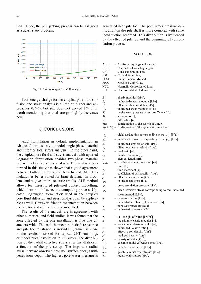
The presented analyses are only pure numericalstudies. The energy plots can be used to verify thiskind of calculation. The FEM solution is based onenergy conservation. Checking different types of en-ergy allows us to study what is happening in themodel as well as how accurate the obtained resultsare. This method of verification is rather dedicated tothe explicit formulation, but can also be useful in im-plicit method. The total energy, the external work andkinetic energy for ALE analysis are plotted in Fig. 11.The change of total energy is 0.05%, which is smalland much lower than 1% suggested for numericallycorrect solution. The kinetic energy represents 13% ofexternal work at the beginning of installation. Thisvalue is dropping to almost zero with large deforma-
(a) (b)
Fig. 10. Distribution of (a) radial total stresses and (b) normalized radial total stresses for five depths after pile installation
Coupled pore fluid diffusionand stress analysis
J. KONKOL, L. BAŁACHOWSKI52
tion. Hence, the pile jacking process can be assignedas a quasi-static problem.
Fig. 11. Energy output for ALE analysis
Total energy change for the coupled pore fluid dif-fusion and stress analysis is a little bit higher and ap-proaches 0.74%, but still does not exceed 1%. It isworth mentioning that total energy slightly decreaseshere.
6. CONCLUSIONS
ALE formulation in default implementation inAbaqus allows us only to model single-phase materialand enforces total stress analysis. On the other hand,the coupled pore fluid and stress analysis with updatedLagrangian formulation enables two-phase materialuse with effective stress analysis. The analysis per-formed in this study has shown that a good agreementbetween both solutions could be achieved. ALE for-mulation is better suited for large deformation prob-lems and it gives more accurate results. ALE methodallows for unrestricted pile–soil contact modelling,which does not influence the computing process. Up-dated Lagrangian formulation used in the coupledpore fluid diffusion and stress analysis can be applica-ble as well. However, frictionless interaction betweenthe pile toe and soil needs to be modelled.
The results of the analysis are in agreement withother numerical and field studies. It was found that thezone affected by the pile installation is five pile di-ameters wide. The ratio between pile shaft resistanceand pile toe resistance is around 0.1, which is closeto the results observed for typical CPT soundingsor model piles installation in OC clays. The distribu-tion of the radial effective stress after installation isa function of the pile set-up. The important radialstress increase observed near soil surface decays withpenetration depth. The highest pore water pressure is
generated near pile toe. The pore water pressure dis-tribution on the pile shaft is more complex with somelocal suction recorded. This distribution is influencedby the effect of pile toe and the beginning of consoli-dation process.
NOTATION
ALE – Arbitrary Lagrangian–Eulerian,CEL – Coupled Eulerian Lagrangian,CPT – Cone Penetration Test,CSL – Critical State Line,FEM – Finite Element Method,MCC – Modified Cam-Clay,NCL – Normally Consolidated Line,UU – Unconsolidated Undrained Test,
E – elastic modulus [kPa],Eu – undrained elastic modulus [kPa],G′ – effective shear modulus [kPa],Gu – undrained shear modulus [kPa],K0 – in-situ earth pressure at rest coefficient [–],M. – stress ratio [–],R – pile radius [m],Y(t) – configuration of the system at time t,Y(t + Δt) – configuration of the system at time t + Δt,
ca0′ – yield surface size corresponding to the cp0′ [kPa],
ua0′ – yield surface size corresponding to the up0′ [kPa],cu – undrained strength of soil [kPa],cd – dilatational wave velocity [m/s],e – void ratio [–],e0 – in-situ void ratio [–],le – element length [m],le,min – smallest element dimension [m],t – time [s],Δt – time increment [s],k – coefficient of permeability [m/s],p′ – effective mean stress [kPa],
0p′ – in-situ mean stress [kPa],
cp′ – preconsolidation pressure [kPa],
up′ – mean effective stress corresponding to the undrainedshear strength [kPa],
q – deviatoric stress [kPa],r – radial distance from pile diameter [m],u – pore water pressure [kPa],u0 – hydrostatic pressure [kPa],
γw – unit weight of water [kN/m3],κ – logarithmic elastic modulus [–],λ – logarithmic plastic modulus [–],νu – undrained Poisson ratio [–],ρ′ – effective soil density [t/m3],ρtot – total soil density [t/m3],ρw – density of water [t/m3],
0rrσ ′ – geostatic radial effective stress [kPa],
rrσ ′ – radial effective stress [kPa],σrr0 – geostatic radial total stresses [kPa],σrr – radial total stresses [kPa],

Large deformation finite element analysis of undrained pile installation 53
σt – tension cut-off [kPa],Φu – undrained angle of internal friction [°],ψ – dilation angle [°].
ACKNOWLEDGEMENTS
The calculations were carried out at the Academic ComputerCentre in Gdańsk (CI TASK).
REFERENCES
[1] ATKINSON J., The mechanics of soils and foundations, CRCPress, 2007.
[2] BIENEN B., QIU G., PUCKER T., CPT correlation developedfrom numerical analysis to predict jack-up foundation pene-tration into sand overlying clay, Ocean Engineering, 2015,108, 216–226, DOI: 10.1016/j.oceaneng.2015.08.009.
[3] BOND A.J., JARDINE R.J., Effects of installing displacementpiles in a high OCR clay, Geotechnique, 1991, 41(3),341–363. DOI: 10.1680/geot.1991.41.3.341.
[4] CUMMINGS A.E., Kerkhoff G.O., Peck R.B., Effect of drivingpiles into soft clay, Transactions of the American Society ofCivil Engineers, 1950, 115(1), 275–285.
[5] DAI Z.H., QIN Z.Z., Numerical and theoretical verification ofmodified cam-clay model and discussion on its problems,Journal of Central South University, 2013, 20, 3305–3313,DOI: 10.1007/s11771-013-1854-7.
[6] Dassault Systémes, 2013, Abaqus 6.13 Analysis User’s Guide,Dassault Systèmes.
[7] DONEA J.H., HUERTA A., PONTHOT J.-PH., RODRÍGUEZ-FERRAN A., Arbitrary Lagrangian–Eulerian Methods, [in:]Encyclopedia of Computational Mechanic, Vol. 1. Funda-mentals, John Wiley & Sons, Ltd., 2004, 413–437, DOI:10.1002/0470091355.ecm009.
[8] HAMANN T., QIU G., GRABE J., Application of a Coupled Eule-rian–Lagrangian approach on pile installation problems underpartially drained conditions, Computers and Geotechnics, 2015,63, 279–290, DOI: 10.1016/j.compgeo.2014.10.006.
[9] KOMURKA V.E., WAGNER A.B., EDIL T.B., A Review of PileSet-Up, Proc., 51st Annual Geotechnical Engineering Con-ference, 2003.
[10] MABSOUT M.E., TASSOULAS J.L., A finite element model forthe simulation of pile driving, International Journal for nu-merical methods in Engineering, 1994, 37(2), 257–278, DOI:10.1002/nme.1620370206.
[11] NOH W.F., CEL: a time-dependent, two-space-dimensional,coupled Eulerian-Lagrangian code. Lawrence Radiation Lab.,Univ. of California, Livermore, 1963.
[12] POTTS D.M., ZDRAVKOVIĆ L., Finite element analysis ingeotechnical engineering: theory, Vol. 1, Thomas Telford,1999, DOI: 10.1680/feaiget.27534.
[13] THO K.K., LEUNG C.F., CHOW Y.K., SWADDIWUDHIPONG S.,Eulerian finite element simulation of spudcan–pile interac-tion, Canadian Geotechnical Journal, 2013, 50(6), 595–608,DOI: 10.1139/cgj-2012-0288.
[14] VERMEER P.A., VERRUIJT A., An accuracy condition forconsolidation by finite elements, International Journal forNumerical and Analytical Methods in Geomechanics, 1981,5(1), 1–14. DOI: 10.1002/nag.1610050103
[15] YI J.T., ZHAO B., LI Y.P., YANG Y., LEE F.H., GOH S.H.,ZHANG X.Y., WU J.F., Post-installation pore-pressure
changes around spudcan and long-term spudcan behaviourin soft clay, Computers and Geotechnics, 2014, 56, 133–147,DOI: 10.1016/j.compgeo.2013.11.007.
[16] ZHOU T.Q., TAN F., LI C., Numerical Analysis for ExcessPore Pressure Dissipation Process for Pressed Pile Installation,Applied Mechanics and Materials, 2013, Vol. 405, 133–137,DOI: 10.4028/www.scientific.net/AMM.405-408.133.
APPENDIX
Fig. A1. Stress paths during undrained shearingwhen initial state of soil is on (a) dry side of the critical line,
(b) wet side of the critical line
The fitting between the undrained shear strength ofthe soil and MCC model can be obtained by the as-sumption of constant void ratio during shearing. Theinitial state of the soil can be on dry or wet side ofcritical line, so two stress paths are possible duringundrained shearing, as is presented in Fig. A1. For thedry side the following equations can be written
⎟⎟⎠
⎞⎜⎜⎝
⎛′′
⋅=−0
0 lnppee c
c κ , (A1)
⎟⎟⎠
⎞⎜⎜⎝
⎛′′
⋅=−u
uu a
pee0
0 lnκ , (A2)
⎟⎟⎠
⎞⎜⎜⎝
⎛′′
⋅=−u
ccu p
pee lnλ . (A3)
Using the assumption of yield surface size in MCCmodel one can write

J. KONKOL, L. BAŁACHOWSKI54
uu pa21
0 = . (A4)
Consequently, equation (A2) can be rewritten as
)2ln(0 ⋅=− κuee . (A5)
Combining equation (A1), (A3) and (A5) we get
)2ln(lnln0
⋅+⎟⎟⎠
⎞⎜⎜⎝
⎛′′
⋅=⎟⎟⎠
⎞⎜⎜⎝
⎛′′
⋅ κλκu
cc
pp
pp . (A6)
Equation (A6) can be transformed to the followingform
u
cc
pp
pp
′′
=⎟⎟⎠
⎞⎜⎜⎝
⎛′′
λκ /
02. (A7)
From definition of stress ratio M (Fig. 6), we knowthat
u
u
acM0
2= . (A8)
Combining equation (A8) and equation (A4) weget
Mcp u
u4
= . (A9)
From equation (A7) and equation (A9) we can de-rive equation (6)
λκλκ /11
/0 )2(4 −− ⎟
⎠⎞
⎜⎝⎛ ′⋅=′ p
Mcp u
c . (A10)
Similar consideration can be made for the wet sideof critical line. We can write the following equations
⎟⎟⎠
⎞⎜⎜⎝
⎛′′
⋅=−0
0 lnppee c
c κ , (A11)
⎟⎟⎠
⎞⎜⎜⎝
⎛′′
⋅=−u
uu a
pee0
0 lnκ , (A12)
⎟⎟⎠
⎞⎜⎜⎝
⎛′′
⋅=−c
uuc p
pee lnλ . (A13)
We can notice that equations (A1) and (A11) aswell as equations (A2) and (A12) are the same. Let ustransform equation (A13) into the following form
⎟⎟⎠
⎞⎜⎜⎝
⎛′′
⋅−=−c
ucu p
pee lnλ . (A14)
Thus, using the power low of logarithm we get
⎟⎟⎠
⎞⎜⎜⎝
⎛′′
⋅=−u
ccu p
pee lnλ . (A15)
Hence, equation (A15) is the same as equation(A3) and the equation for the preconsolidation pressu-re is the same for wet and dry side of the critical lineand it is described by equation (A15) and (6).