Large Capacity Multi VRF System DC Inverter …Variable Refrigerant Flow System Large Capacity Multi...
12
Multi Air Conditioning System for Buildings Variable Refrigerant Flow System Large Capacity Multi VRF System DC Inverter Control Compressor Long Piping System Design High Efficiency Refrigerant R410A
Transcript of Large Capacity Multi VRF System DC Inverter …Variable Refrigerant Flow System Large Capacity Multi...
Multi Air Conditioning System for Buildings
Variable Refrigerant Flow System
Large Capacity Multi VRF System
DC Inverter Control Compressor
Long Piping System Design
High Efficiency Refrigerant R410A
DiAmon
New Stamp
2
CapacityModel name
Capacity range
16
15
30
32
48
28.022.4
40.044.850.456.062.468.0
80.072.8
84.090.496.0102108120
HP
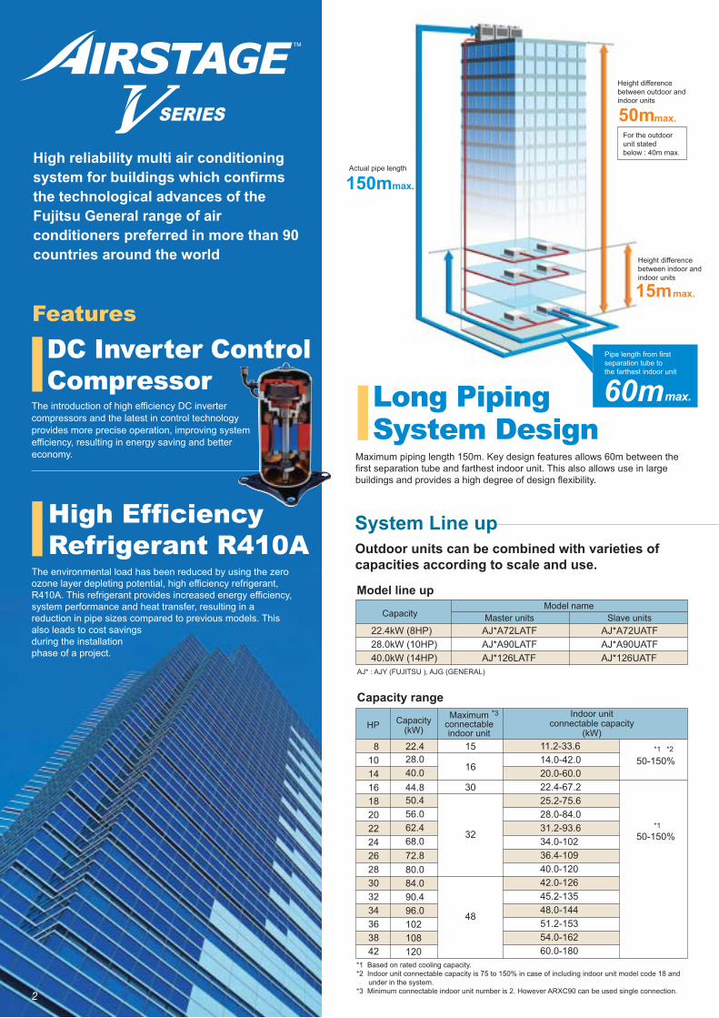
Model line up
Outdoor units can be combined with varieties of capacities according to scale and use.
The introduction of high efficiency DC inverter compressors and the latest in control technology provides more precise operation, improving system efficiency, resulting in energy saving and better economy.
System Line up
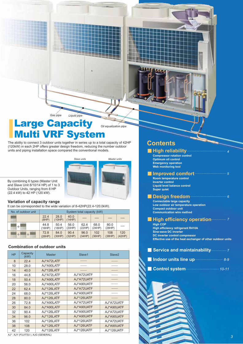
AJ* : AJY (FUJITSU ), AJG (GENERAL)
*1 Based on rated cooling capacity.*2 Indoor unit connectable capacity is 75 to 150% in case of including indoor unit model code 18 and under in the system.*3 Minimum connectable indoor unit number is 2. However ARXC90 can be used single connection.
Master units Slave units22.4kW (8HP)28.0kW (10HP)40.0kW (14HP)
AJ*A72UATFAJ*A90UATFAJ*126UATF
AJ*A72LATFAJ*A90LATFAJ*126LATF
Capacity(kW)
Indoor unitconnectable capacity
(kW)
Maximumconnectableindoor unit
11.2-33.614.0-42.020.0-60.022.4-67.225.2-75.628.0-84.031.2-93.634.0-10236.4-10940.0-12042.0-12645.2-13548.0-14451.2-15354.0-16260.0-180
50-150%
50-150%*1
*1
*2
*3
Features
8101416182022242628303234363842
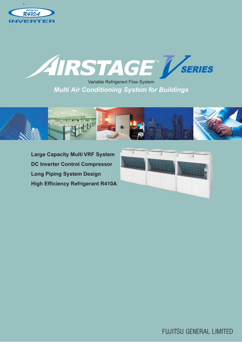
Maximum piping length 150m. Key design features allows 60m between the first separation tube and farthest indoor unit. This also allows use in large buildings and provides a high degree of design flexibility.
Long Piping System Design
Actual pipe length
max.50mFor the outdoor unit stated below : 40m max.
Height difference between outdoor and indoor units
15mmax.
Height difference between indoor and indoor units
150mmax.
60mmax.
Pipe length from first separation tube to the farthest indoor unit
DC Inverter Control Compressor
High Efficiency Refrigerant R410A
High reliability multi air conditioning system for buildings which confirms the technological advances of the Fujitsu General range of air conditioners preferred in more than 90 countries around the world
The environmental load has been reduced by using the zero ozone layer depleting potential, high efficiency refrigerant, R410A. This refrigerant provides increased energy efficiency, system performance and heat transfer, resulting in a reduction in pipe sizes compared to previous models. This also leads to cost savings during the installation phase of a project.
3
High reliability
Improved comfort
Design freedom
High efficiency operation
Contents
Compressor rotation control
Optimum oil control
Emergency operation
Web monitoring tool
Oil equalization pipe
Connectable large capacity
Low outdoor air temperature operation
Compact outdoor unit
Communication wire method
Room temperature control
Inverter control
Liquid level balance control
Super quiet
High COP
High efficiency refrigerant R410A
Sine-wave DC inverter
DC inverter control compressor
Effective use of the heat exchanger of other outdoor units
4
5
6
7
7
8-9
10-11
Variation of capacity range
40.028.0
90.4 96.0 102 108 12084.072.8
56.0 62.4 68.0 80.050.4
No. of outdoor unit System total capacity (kW)
Combination of outdoor units
HP Master Slave1 Slave2
The ability to connect 3 outdoor units together in series up to a total capacity of 42HP (120kW) in each 2HP offers greater design freedom, reducing the number outdoor units and piping installation space compared the conventional models.
Large Capacity Multi VRF System
It can be corresponded to the wide variation of 8-42HP(22.4-120.0kW).
AJ* : AJY (FUJITSU ), AJG (GENERAL)
Capacity(kW)
AJ*A72LATF
AJ*A90LATF
AJ*126LATF
AJ*A72LATF
AJ*A90LATF
AJ*A90LATF
AJ*126LATF
AJ*126LATF
AJ*126LATF
AJ*A90LATF
AJ*A90LATF
AJ*126LATF
AJ*126LATF
AJ*126LATF
AJ*126LATF
AJ*126LATF
AJ*A72UATF
AJ*A72UATF
AJ*A90UATF
AJ*A72UATF
AJ*A90UATF
AJ*126UATF
AJ*A72UATF
AJ*A90UATF
AJ*A90UATF
AJ*A90UATF
AJ*126UATF
AJ*126UATF
AJ*126UATF
AJ*A72UATF
AJ*A90UATF
AJ*A72UATF
AJ*A90UATF
AJ*A72UATF
AJ*A90UATF
AJ*126UATF
By combining 6 types (Master Unit and Slave Unit 8/10/14 HP) of 1 to 3 Outdoor Units, ranging from 8 HP (22.4 kW) to 42 HP (120 kW).
Service and maintainability
Indoor units line up
Control system
22.4
28.0
40.0
44.8
50.4
56.0
62.4
68.0
80.0
72.8
84.0
90.4
96.0
102
108
120
(10HP)
(18HP)
22.4
44.8
(8HP)
(16HP)
(26HP)
(14HP)
(20HP)
(30HP) (32HP)
(22HP) (24HP)
(34HP) (36HP)
(28HP)
(38HP) (42HP)
Gas pipe Liquid pipe
8
10
14
16
18
20
22
24
28
26
30
32
34
36
38
42
Master unitsSlave units
4
Compressor rotation control Emergency operation
Indoor unit
Outdoor unit
Optimum oil control
Web monitoring tool
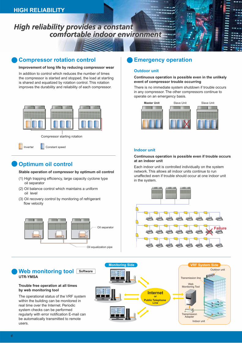
In addition to control which reduces the number of times
the compressor is started and stopped, the load at starting
is shared and equalized by rotation control. This rotation
improves the durability and reliability of each compressor.
(1) High trapping efficiency, large capacity cyclone type
oil separator
(2) Oil balance control which maintains a uniform
oil level
(3) Oil recovery control by monitoring of refrigerant
flow velocity
The operational status of the VRF system
within the building can be monitored in
real time over the Internet. Periodic
system checks can be performed
regularly with error notification E-mail can
be automatically transmitted to remote
users.
There is no immediate system shutdown if trouble occurs
in any compressor. The other compressors continue to
operate on an emergency basis.
Each indoor unit is controlled individually on the system
network. This allows all indoor units continue to run
unaffected even if trouble should occur at one indoor unit
in the system.
Slave Unit Slave UnitMaster Unit
Failure
Compressor starting rotation
Constant speedInverter
Improvement of long life by reducing compressor wear
Stable operation of compressor by optimum oil control
Continuous operation is possible even in the unlikely
event of compressor trouble occurring
Continuous operation is possible even if trouble occurs
at an indoor unit
Trouble free operation at all times
by web monitoring tool
UTR-YMSA
Oil separator
Oil equalization pipe
HIGH RELIABILITY
Software
VRF System SideMonitoring Side
Internetor
Public Telephone Line
Indoor unit
Transmission line
TransmissionAdapter
Outdoor unit
WebMonitoring Tool
5
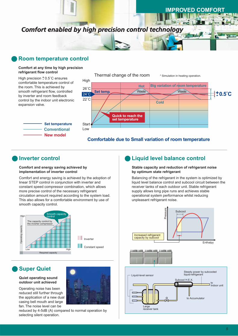
Liquid level balance control
Room temperature control
Balancing of the refrigerant in the system is optimized by
liquid level balance control and subcool circuit between the
receiver tanks of each outdoor unit. Stable refrigerant
supply allows long pipe runs and achieves stable
operational system performance whilst reducing
unpleasant refrigerant noise.
Inverter control
Comfort and energy saving is achieved by the adoption of
linear STEP control in conjunction with inverter and
constant speed compressor combination, which allows
more precise control of the necessary refrigerant
circulation amount required according to the system load.
This also allows for a comfortable environment by use of
smooth capacity control.
Constant speed
Inverter
Comfort and energy saving achieved by
implementation of inverter control
High precision +- 0.5˚C ensures
comfortable temperature control of
the room. This is achieved by
smooth refrigerant flow, controlled
by inverter and room feedback
control by the indoor unit electronic
expansion valve.
Comfort at any time by high precision
refrigerant flow control
Cold
Hot
Thermal change of the room
Set temp.
Low
High
Start
Comfortable due to Small variation of room temperature
24˚C
26˚C
22˚C
WasteWaste
Big variation of room temperature
* Simulation in heating operation.
Conventional
New model
Set temperature
+- 0.5˚C
Stable capacity and reduction of refrigerant noise
by optimum state refrigerant
Super Quiet
Operating noise has been
reduced still further through
the application of a new dual
casing bell mouth and large
fan. The noise level can be
reduced by 4-5dB (A) compared to normal operation by
selecting silent operation.
Quiet operating sound
outdoor unit achieved
Required capacity
Op
era
tin
g c
ap
acity
High
High
Low
The capacity control by the inverter compressor
Smooth capacitycontrol
Subcool H.E.X.to Indoor unit
Liquid-level sensor
to Accumulator
Largereceiver tank
Steady power by subcooledliquid-refrigerant
Subcool
Pre
ssu
re
Enthalpy
Increased refrigerant capacity by subcool
Quick to reach the set temperature
IMPROVED COMFORT
6
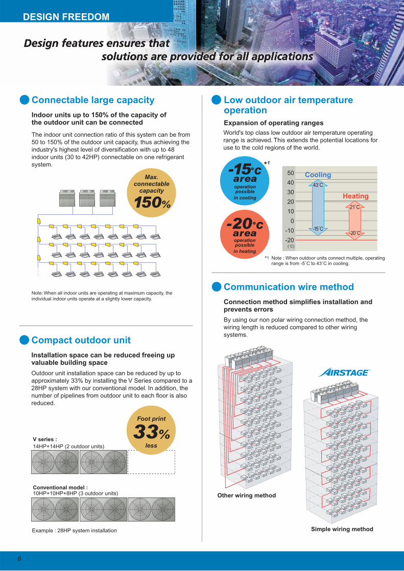
Communication wire method
By using our non polar wiring connection method, the
wiring length is reduced compared to other wiring
systems.
Max.connectable
capacity
150%
Example : 28HP system installation
V series :
14HP+14HP (2 outdoor units)
Conventional model : 10HP+10HP+8HP (3 outdoor units)
Connection method simplifies installation and prevents errors
Low outdoor air temperature operation
World's top class low outdoor air temperature operating
range is achieved. This extends the potential locations for
use to the cold regions of the world.
Expansion of operating ranges
Compact outdoor unit
Outdoor unit installation space can be reduced by up to
approximately 33% by installing the V Series compared to a
28HP system with our conventional model. In addition, the
number of pipelines from outdoor unit to each floor is also
reduced.
Installation space can be reduced freeing up valuable building space
Connectable large capacity
The indoor unit connection ratio of this system can be from
50 to 150% of the outdoor unit capacity, thus achieving the
industry's highest level of diversification with up to 48
indoor units (30 to 42HP) connectable on one refrigerant
system.
Note: When all indoor units are operating at maximum capacity, the
individual indoor units operate at a slightly lower capacity.
Indoor units up to 150% of the capacity of the outdoor unit can be connected
50
40
30
20
10
0
-10
-20(˚C)
Heating
43˚C
-15˚C
21˚C
-20˚C
Coolingarea-15°C
in cooling
area-20°C
operationpossible
operationpossible
Foot print
33%less
DESIGN FREEDOM
in heating
Simple wiring method
Other wiring method
*1
*1
Note : When outdoor units connect multiple, operating range is from -5˚C to 43˚C in cooling.
7
High efficiency refrigerant R410A
Sine-wave DC Inverter
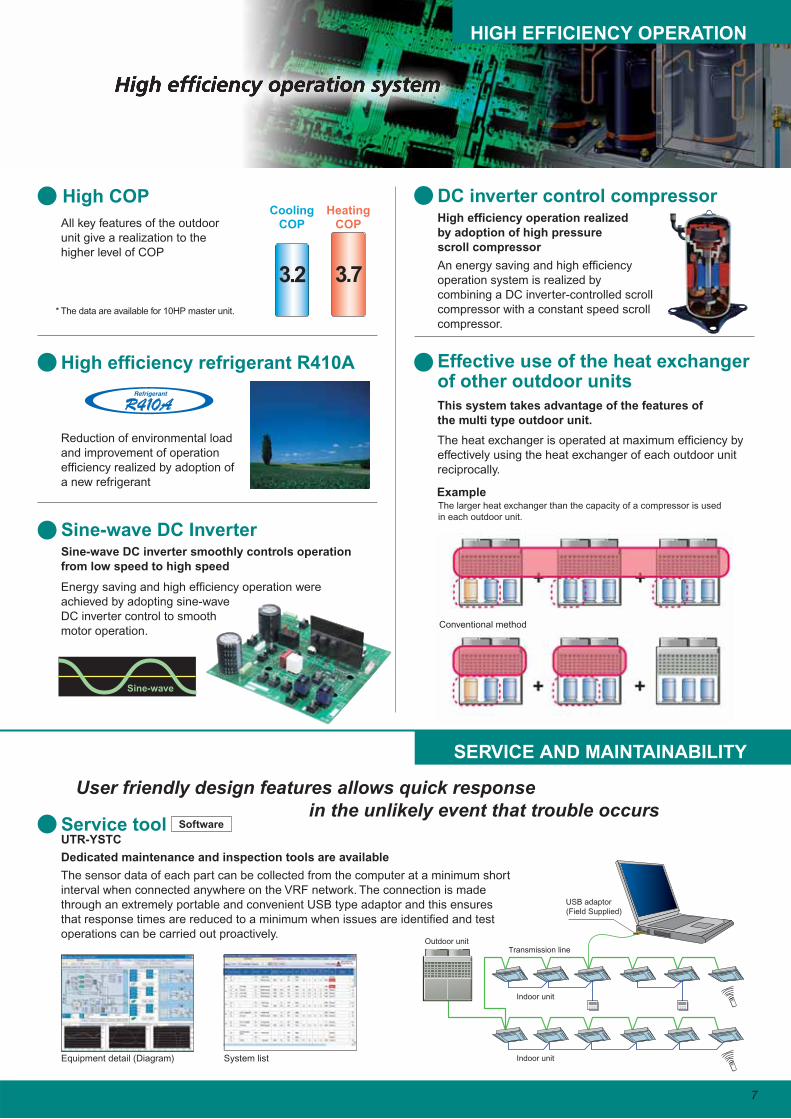
Energy saving and high efficiency operation were
achieved by adopting sine-wave
DC inverter control to smooth
motor operation.
DC inverter control compressor
An energy saving and high efficiency
operation system is realized by
combining a DC inverter-controlled scroll
compressor with a constant speed scroll
compressor.
High efficiency operation realized
by adoption of high pressure
scroll compressor
Sine-wave DC inverter smoothly controls operation
from low speed to high speed
High COP
All key features of the outdoor
unit give a realization to the
higher level of COP
Reduction of environmental load
and improvement of operation
efficiency realized by adoption of
a new refrigerant
Effective use of the heat exchanger of other outdoor units
The heat exchanger is operated at maximum efficiency by
effectively using the heat exchanger of each outdoor unit
reciprocally.
This system takes advantage of the features of
the multi type outdoor unit.
Service tool
The sensor data of each part can be collected from the computer at a minimum short
interval when connected anywhere on the VRF network. The connection is made
through an extremely portable and convenient USB type adaptor and this ensures
that response times are reduced to a minimum when issues are identified and test
operations can be carried out proactively.
Dedicated maintenance and inspection tools are available
UTR-YSTC
* The data are available for 10HP master unit.
HeatingCOP
CoolingCOP
User friendly design features allows quick response
in the unlikely event that trouble occurs
Equipment detail (Diagram) System list
Sine-wave
HIGH EFFICIENCY OPERATION
SERVICE AND MAINTAINABILITY
ExampleThe larger heat exchanger than the capacity of a compressor is used
in each outdoor unit.
Conventional method
3.73.2
Transmission line
Indoor unit
Indoor unit
Outdoor unit
USB adaptor(Field Supplied)
Software
9 1412 20187
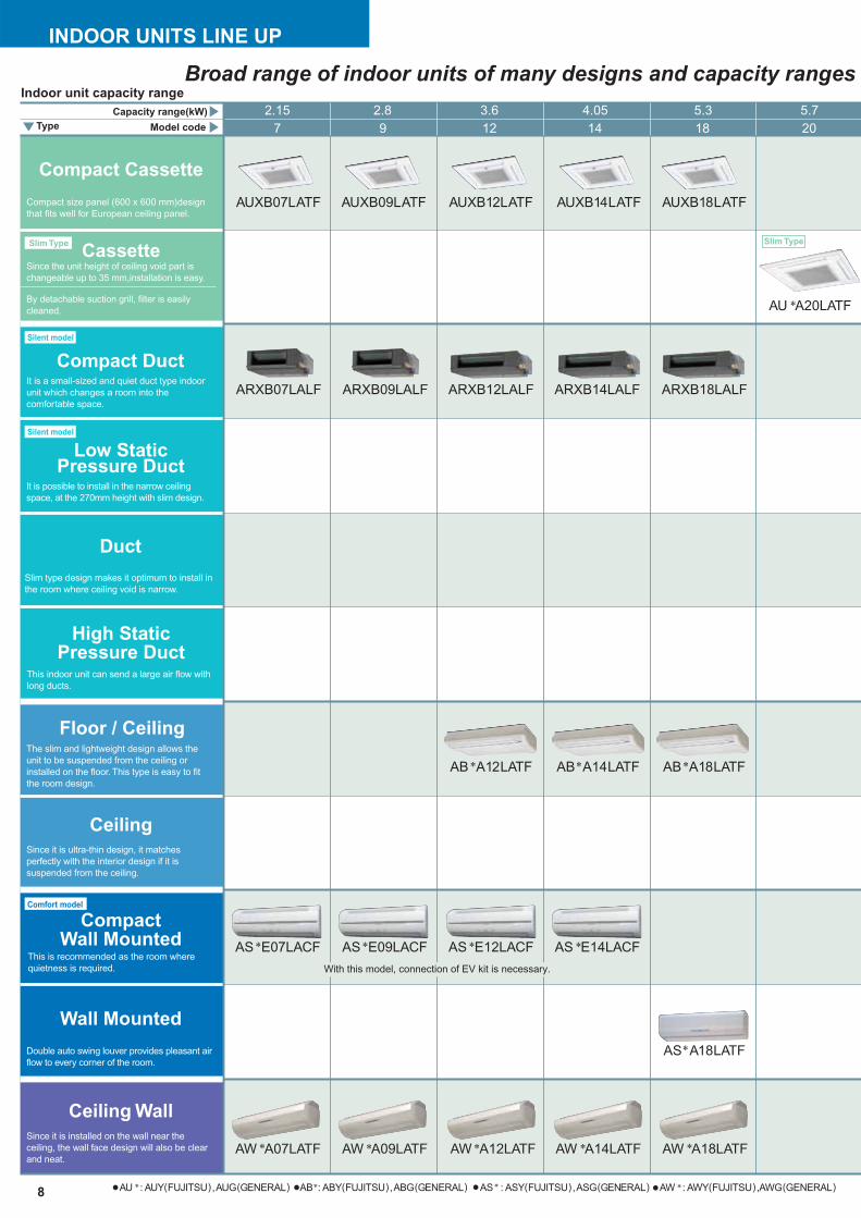
Cassette
Floor / Ceiling
Ceiling
Wall Mounted
Ceiling Wall
Compact Duct
Low StaticPressure Duct
Duct
High StaticPressure Duct
Compact Cassette
Slim Type
Silent model
Silent model
Slim Type
Comfort model
ARXB18LALFARXB07LALF ARXB09LALF ARXB14LALFARXB12LALF
2.15 2.8 3.6 4.05 5.3 5.7
Since it is installed on the wall near the
ceiling, the wall face design will also be clear
and neat.
Double auto swing louver provides pleasant air
flow to every corner of the room.
Since it is ultra-thin design, it matches
perfectly with the interior design if it is
suspended from the ceiling.
The slim and lightweight design allows the
unit to be suspended from the ceiling or
installed on the floor. This type is easy to fit
the room design.
Slim type design makes it optimum to install in
the room where ceiling void is narrow.
It is possible to install in the narrow ceiling
space, at the 270mm height with slim design.
It is a small-sized and quiet duct type indoor
unit which changes a room into the
comfortable space.
By detachable suction grill, filter is easily
cleaned.
Since the unit height of ceiling void part is
changeable up to 35 mm,installation is easy.
Compact size panel (600 x 600 mm)design
that fits well for European ceiling panel.
This indoor unit can send a large air flow with
long ducts.
AUXB07LATF AUXB09LATF AUXB12LATF AUXB14LATF AUXB18LATF
AU A20LATF
AB A12LATF AB A14LATF AB A18LATF
CompactWall Mounted
This is recommended as the room where
quietness is required.
AS E07LACF AS E09LACF AS E12LACF AS E14LACF
AS A18LATF
AW A07LATF
AU : AUY(FUJITSU),AUG(GENERAL) AB : ABY(FUJITSU),ABG(GENERAL) AS : ASY(FUJITSU),ASG(GENERAL) AW : AWY(FUJITSU),AWG(GENERAL)
AW A09LATF AW A12LATF AW A14LATF AW A18LATF
Capacity range(kW)
Indoor unit capacity range
Model codeType
Broad range of indoor units of many designs and capacity ranges
8
INDOOR UNITS LINE UP
With this model, connection of EV kit is necessary.
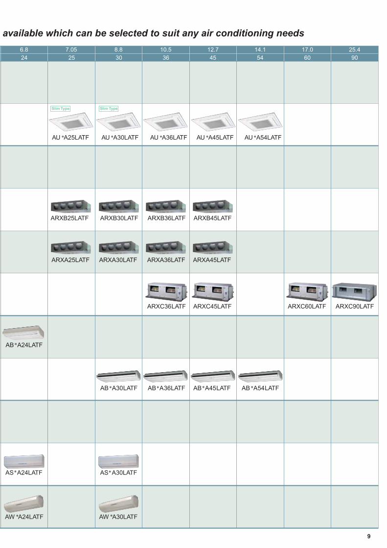
3624 60 9045 543025
Slim Type Slim Type
6.8 7.05 10.5 17.0 25.412.7 14.18.8
ARXB25LATF ARXB30LATF ARXB36LATF ARXB45LATF
AU A36LATFAU A25LATF AU A30LATF AU A45LATF AU A54LATF
AB A24LATF
AB A30LATF AB A36LATF AB A45LATF AB A54LATF
AS A24LATF AS A30LATF
AW A24LATF AW A30LATF
ARXA25LATF ARXA30LATF ARXA36LATF ARXA45LATF
ARXC90LATFARXC36LATF ARXC60LATFARXC45LATF
available which can be selected to suit any air conditioning needs
9
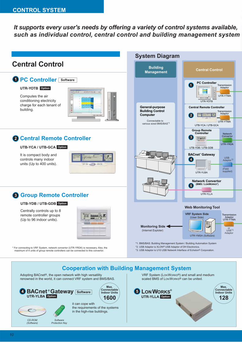
BACnet Gateway
*2. USB Adaptor is XLON USB Adaptor of DH Electronics.
*3. USB Adaptor is U10 USB Network Interface of Echelon Corporation.
*1. BMS/BAS: Building Management System / Building Automation System
Central Control
BACnet Gateway
General-purpose
Building Control
Computer
Building
Management
UTR-YLBA
Network Convertor (BMS / LONWORKS
®)
UTR-YLLA
TransmissionAdaptor
NetworkConvertor
UTR-YRDA
UTR-YTMA
UTR-YTMA
UTR-YOTB
UTB-YCA / UTB-GCA
PC Controller
Central Remote Controller
Group RemoteController
UTB-YDB / UTB-GDB
TransmissionAdaptor
TransmissionAdaptor
UTR-YTMA
USB Adaptor
(Field supplied)
*2
orUSB
Adaptor
*3
®
®
®
®
Connectable tovarious sized BMS/BAS
Web Monitoring Tool
Monitoring Side
UTR-YMSA (Software)
*1
VRF System Side(User Side)
(Internet Exploler)
UTB-YCA / UTB-GCA
10
PC Controller
UTR-YOTB Option
UTR-YLBA Option Option
Option
Option
Central Remote Controller
LONWORKS UTR-YLLA
Max.ConnectableIndoor Units
1281600
Cooperation with Building Management System
UTB-YDB / UTB-GDB
Group Remote Controller
CONTROL SYSTEM
Computes the air
conditioning electricity
charge for each tenant of
building.
It is compact body and
controls many indoor
units (Up to 400 units).
Centrally controls up to 8
remote controller groups
(Up to 96 indoor units).
Adopting BACnet®, the open network with high versatility renowned in the world, it can connect VRF system and BMS/BAS.
VRF System (LONWORKS®) and small and medium scaled BMS of LONWORKS® can be united.
it can cope with the requirements of the systems in the high-rise buildings.
* For connecting to VRF System, network convertor (UTR-YRDA) is necessary. Also, the maximum of 4 units of group remote controllers can be connected to this convertor.
Software
System Diagram
Central Control
Max.ConnectableIndoor Units
®
CD-ROM(Software)
SoftwareProtection Key
Software
1
1
4
5
2
32
3
4 5
It supports every user's needs by offering a variety of control systems available,
such as individual control, central control and building management system
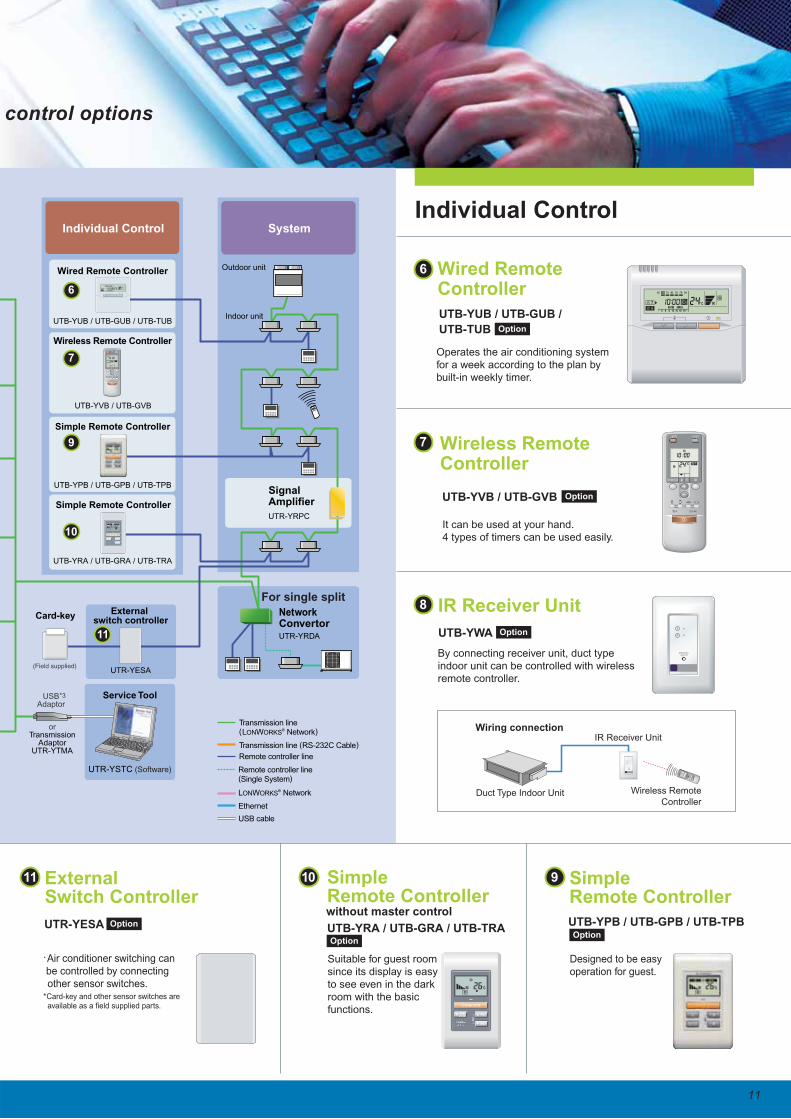
SystemIndividual Control
Outdoor unit
Indoor unit
SignalAmplifier
UTR-YRPC
Transmission line (LONWORKS
® Network)
Transmission line (RS-232C Cable)
Remote controller line
Remote controller line (Single System)
Ethernet
USB cable
LONWORKS® Network
Service Tool
UTR-YSTC (Software)
orTransmission
AdaptorUTR-YTMA
UTB-YUB / UTB-GUB / UTB-TUB
Wired Remote Controller
UTB-YVB / UTB-GVB
Wireless Remote Controller
UTB-YPB / UTB-GPB / UTB-TPB
UTB-YRA / UTB-GRA / UTB-TRA
Simple Remote Controller
Simple Remote Controller
USBAdaptor
*3
SU MO TU WE TH FR SA
7
3 126 9 15 18 21
External switch controller
Card-key
UTR-YESA(Field supplied)
For single split
11
Wired Remote Controller
UTB-YUB / UTB-GUB /
UTB-TUB
Wireless Remote Controller
without master control
UTB-YVB / UTB-GVB
UTB-YWA
IR Receiver Unit
Wireless Remote
Controller
IR Receiver Unit
Duct Type Indoor Unit
Wiring connection
UTB-YPB / UTB-GPB / UTB-TPB
Simple Remote Controller
UTB-YRA / UTB-GRA / UTB-TRA
Simple Remote Controller
Individual Control
Option
Option
Option
OptionOption
It can be used at your hand.4 types of timers can be used easily.
Operates the air conditioning system for a week according to the plan by built-in weekly timer.
By connecting receiver unit, duct type indoor unit can be controlled with wireless remote controller.
Suitable for guest room since its display is easy to see even in the dark room with the basic functions.
Designed to be easy operation for guest.
6
6
7
9
11
10
7
8
10 9
UTR-YESA
External Switch Controller
Option
.Air conditioner switching can be controlled by connecting other sensor switches.*Card-key and other sensor switches are available as a field supplied parts.
11
NetworkConvertorUTR-YRDA
control options
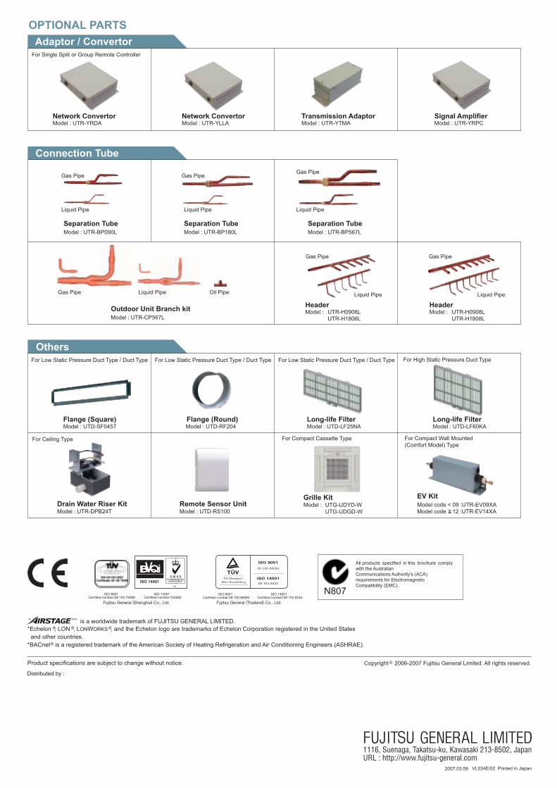
OPTIONAL PARTS
Network Convertor Network ConvertorModel : UTR-YRDA Model : UTR-YLLA Model : UTR-YTMA
Transmission AdaptorModel : UTR-YRPCSignal Amplifier
Adaptor / Convertor
Connection Tube
Others
Separation TubeModel : UTR-BP090L Model : UTR-BP180L
Separation TubeModel : UTR-BP567LSeparation Tube
Gas Pipe
Liquid Pipe
Gas Pipe
Liquid Pipe
Gas Pipe
Liquid Pipe
Outdoor Unit Branch kitModel : UTR-CP567L
Gas Pipe Liquid Pipe Oil Pipe
Flange (Square) Flange (Round)Model : UTD-SF045T Model : UTD-RF204
Drain Water Riser KitModel : UTR-DPB24T
Long-life FilterModel : UTD-LF25NA
Long-life FilterModel : UTD-LF60KA
Model : UTD-RS100Remote Sensor Unit
Grille KitModel : UTG-UDYD-W
UTG-UDGD-W
For Single Split or Group Remote Controller
VL034E/02 Printed in Japan
N807
All products specified in this brochure comply with the Australian Communications Authority's (ACA)requirements for Electromagnetic Compatibility (EMC).
”” is a worldwide trademark of FUJITSU GENERAL LIMITED.
Product specifications are subject to change without notice.
*Echelon , LON , LONWORKS , and the Echelon logo are trademarks of Echelon Corporation registered in the United States and other countries.*BACnet is a registered trademark of the American Society of Heating Refrigeration and Air Conditioning Engineers (ASHRAE).
Distributed by :
Copyright 2006-2007 Fujitsu General Limited. All rights reserved.
For Compact Cassette Type
For High Static Pressure Duct TypeFor Low Static Pressure Duct Type / Duct TypeFor Low Static Pressure Duct Type / Duct TypeFor Low Static Pressure Duct Type / Duct Type
HeaderModel : UTR-H0906L
UTR-H1806L
HeaderModel : UTR-H0908L
UTR-H1808L
Model code < 09 :UTR-EV09XAModel code 12 :UTR-EV14XA
EV Kit
For Compact Wall Mounted (Comfort Model) Type
For Ceiling Type
2007.03.09
Gas Pipe
Liquid Pipe
Gas Pipe
Liquid Pipe