
steel bridge bearing steel bridge bearing selection and design ...

TURNING IDEAS INTO ENGINEERED SOLUTIONS
Large Bearing Design Manual and Product Selection Guide
www.kaydonbearings.com

2 |www.kaydonbearings.com 1-800-514-3066
Table of ContentsPage Number
Section 1 — Introduction ........................................................................................................2 • Capabilities • Design Features • Preliminary Selection Guide • Application and Load Analysis • Typical Mountings
Section 2 — Stock Turntable Bearings ...................................................................................12 • MT-Series Bearings Selection Tables and Load Ratings • RK-Series Bearings Selection Tables and Load Ratings
Section 3 — Other Products ...................................................................................................16 • Custom Four-Point Contact Ball Bearings • Eight-Point Contact Ball Bearings • WireX® Roller Bearings • KH-Series Pre-engineered High Precision Bearing Assemblies • Custom Bearing Capabilities
Section 4 — Load Rating Charts .............................................................................................23 • Load Rating Charts MT-Series, RK-Series, 4-Point Contact, 8-Point Contact
Section 5 — Installation and Maintenance .............................................................................25 • Installation and Care of Kaydon Bearings • Design Considerations (for the equipment designer) • Installation Instructions (for the equipment builder) • Maintenance Instructions (for the equipment user)
Section 6 — Appendix and Sales Information ........................................................................32 • Application Data Form • Warranty Information • Engineering Design Aids and Technical Literature
Large Bearing Catalog 390 ©KAYDON® Corporation 2004

1-800-514-3066 www.kaydonbearings.com|3
Introduction
Kaydon Capabilities
Kaydon has been America’s leading pro-ducer of large diameter custom bearings since its founding in 1941. Manufactur-ing operations have expanded steadily to meet ever growing market needs since 1976.
Kaydon manufactures bearings up to 180 inches outside diameter using the most modern facilities and equipment in the industry. Continuing expansion and manufacturing versatility have led to our position as the leading supplier of all types of large diameter combination load bearings. Kaydon is unique in the breadth of product capabilities offered, always striving to match the best bearing type with your application needs.
Standard bearings
Kaydon’s long history of serving the needs of equipment and manufacturers has resulted in two series of standard bearings to fi t many common application needs. The RK-Series of lightweight turntable bearings have proven capable of satisfying many requirements at mod-erate cost—with the advantages of short lead time or stock availability. The new, expanded MT-Series of standard turnta-ble bearings combine quick delivery with maximum capacity and value to fi t an even wider variety of applications. Many other bearings shown in this catalog are produced on a regular basis and offer short lead time at moderate cost.
Custom bearings
While other manufacturers may special-ize in one or two specifi c bearing types, Kaydon’s broad experience and capabili-ties allow us to match the product to your requirements—not ours. Where a special need exists, Kaydon can fi ll it without sacrifi cing system performance. Often, we can supply bearings which fi ll the need with minimal alteration or additional costs to the design. For truly unique applications, our fully staffed
engineering department can design the optimum solution.
Bearing types
• Four-point contact ball bearings, as well as Kaydon’s patented 8-point contact ball bearings, are used as swing bearings in cranes, excavators, aerial platforms and other types of construc- tion and material handling equipment. These bearings have also been applied successfully in machine tools, radar and medical equipment.
• Biangular roller bearings are used in applications demanding higher preci- sion and stiffness but requiring less static load capacity, such as index tables, positioners, antenna mounts and military gun turrets.
• Inserted raceway–WireX®–bearings with single, double or triple rows offer important weight savings advantages and are found in high performance applications such as military vehicle turrets.
• Plastic ball 4-point contact and angular contact thrust bearings are also available for specialized applications.
Total capabilities
Kaydon offers the bearings to fi t your needs. Ball and roller types in single and multi-row designs. Solid or inserted wire raceways. Geared raceways, both inter-nal and external. Bearings for radial, thrust, moment and combined loading. Capacities, materials, seals and confi gu-rations to fi t a variety of applications. And the design and application engi-neering service that has tailored the best bearing values to the world’s toughest bearing applications.
If you don’t see what you want in this catalog, call us at (231) 755-3741. We will be glad to supply technical assis-tance, lead time information and quota-tions on bearings to fi ll your requirements or specifi cations.
PrecisionMany devices, such as machine tool tables and radar antennas, require a high degree of accuracy and are de-pendent upon the bearings to achieve it. A single four-point contact ball or biangular roller bearing is ideal for these applications. Integral gears and mounting holes reduce the number of components and tolerance buildup, resulting in maximum accuracy and simplifi cation of design. Early consul-tation with Kaydon can be invaluable in determining the optimum bearing and mounting.
The bearings listed in this catalog are manufactured to a standard precision suitable for many commercial applica-tions, but Kaydon also manufactures bearings of higher precision. The engineering principles discussed in the manual also apply to bearings of any precision level.
Bearings with radial and axial runouts of less than .0002 inches T.I.R. and gears of AGMA Class #10 or better can be furnished. Where extreme rigidity is required, very high spring rates can be maintained. Kaydon achieves these results through the use of modern precision equipment, experienced personnel, and specially developed manufacturing techniques.
Combined with other features of large diameter bearings—high load capacity, small space requirement, large center hole, grease lubrication, and ease of installation, high precision and rigid-ity make possible greatly improved performance in such applications as:
• Grinding machines• Turning and boring machines• Index tables• Scientifi c and medical instruments• Radar, height fi nders, positioners and gun directors• Ocular and radio telescopes• Logging machinery• Material handling equipment
©KAYDON® Corporation 2004 Large Bearing Catalog 390 S
ectio
n 1
–In
trod
uctio
n

Bearing Design Features
Whether used in heavy-duty off-road vehicles, precision medical equipment or high accuracy military radars, large diam-eter Kaydon bearings share many design features. There are important differences however, which often dictate the optimal bearing selection for a given application. These pages outline the primary features of each bearing type.
Turntable bearing advantages
Over the years demands have increased for equipment economy, performance, and reliability. As a result, four-point and eight-point contact ball bearings have replaced the older, less effi cient hook rollers and kingpost assemblies. Turntable bearings provide smooth rota-tion and high radial, thrust and moment load capacity in a compact dimensional envelope. With a Kaydon turntable bear-ing there is no need for a center shaft or kingpost, so the bearing center space is open and available for hydraulic piping or conduit runs.
Additionally, turntable bearings in-cor-porate many special features such as integral gearing, through-drilled or tapped mounting holes and contact seals. These features simplify the job of the equipment designer, lower manufacturing costs, and facilitate system maintenance.
Importance of proper selec-tion, installation and use
Turntable bearing applications are typi-fi ed by heavy loading and slow, intermit-tent or partial rotation.
Bearing failure is therefore seldom due to classic rolling contact fatigue. In other words, calculated bearing life is not usu-ally a major consideration in turntable applications, especially in construction equipment.
Turntable bearings are usually selected on the basis of static load capacity, suit-able integral gearing, and other special features. Turntable bearing failure is often the result of practical consider-
ations not covered by classical rolling bearing theory—such as nonuniform support structure design, lack of lubrica-tion, improper selection or application of fasteners, overloading beyond equip-ment specifi cations, and other abuses.
The purpose of this manual is to provide guidelines for system design and turn-table bearing application, and to caution equipment designers and users of one principle: Large-diameter bearings are not commodity products. Each bearing is a custom design or a custom application of an existing bearing design. In either case, the bearing manufacturer should be involved in the design stage.
Four-point contact ball bearings
Four-point contact ball bearings can accept combinations of radial, thrust and moment loads. This is possible due to the unusual geometry of the raceways (or ball grooves). The ball groove in each race has two radii that are larger than the ball radius. The centers of these two radii are offset from the center of the ball radius. This results in a “Gothic Arch” confi guration in each of the raceway grooves, making it possible for the two grooves to contact the ball at four points.
High thrust and moment capacity is ob-tained in a four-point contact ball bear-ing by its deep raceway grooves. These allow high initial contact angles between the balls and raceways and increase the thrust and moment capacity. The deep grooves also accommodate the contact angle increase which results from ring stretch and ball defl ection under load.
Precision grinding of raceways is nec-essary to control accuracy of contact
angles, close ball to raceway conformity, diametral clearance and raceway fi nish. These design features, along with proper material selection, assure the proper function of the four-point contact ball bearing.
Eight-point contact ball bearings
The eight-point contact ball bearing was developed by Kaydon to satisfy require-ments for maximum load capacity within a given envelope, especially in larger size bearings.
As shown below the eight-point contact ball bearing is an annular bearing with two rows of balls. The unique feature of this bearing lies in the utilization of the “Gothic Arch” or four-point contact internal geometry in both rows.
Functionally, the bearing may be con-sidered to be two single row, four-point contact bearings with adjacent faces.
The four points of contact permit each row of balls to accept radial, axial, or moment loads, or a combination of the three. Through precise grinding tech-niques, raceways are closely matched for parallelism and size, providing a high degree of load sharing between rows. Test results have confi rmed that the second row of balls provides and additional 80% capacity over that provided by a single row.
Biangular roller bearings
Biangular roller (cross roller) bearings will support the same types of load asthe four-point and eight-point contact ball bearings.
4 |www.kaydonbearings.com 1-800-514-3066
Large Bearing Catalog 390 ©KAYDON® Corporation 2004S
ecti
on
1–
Intr
od
uct
ion

To accomplish this universal load carry-ing capability, the bearing is designed with V-groove raceways, providing two roller paths in each ring. The rollers have a length slightly less than their diameter and are positioned so that adjacent rollers contact different sets of raceways, with the axes at right angles to each other. Positioned in this manner the rollers transmit load along perpen-dicular sets of 45° contacts. The action of the bearing under various types of loading is thus analogous to that of the four-point contact ball bearing.
While a roller of length and diameter approximating a given diameter of ball has more load carrying capacity, the static thrust and moment capacity of a biangular roller bearing is less than that of a four-point contact ball bear-ing of comparable size. The reason for this is that only alternate rollers resist a uni-directional axial load. In some cases, capacity in one axial direction may be increased by orienting more rollers along one axis than the other, with a resultingdecrease in capacity in the opposite direction.
The main advantages of biangular roller bearings are greater stiffness and conse-quent superior spring rate, as well as tolerance of mounting surface irregu-larities and resulting defl ections. When defl ection under load must be minimized, or when bearing turning torque is criti-cal this bearing may be given preference over a four-point contact ball bearing.
WireX® inserted raceway bearings
WireX® bearings are generally used in applications requiring maximum weight reduction and corrosion resistance. They are generally custom designed to support specifi c combinations of radial, thrust and moment loads. Gear teeth can be cut in the inner or outer ring, and bolt holes provided for mounting.
The bearing rings have machined seats to position the inserted wire raceways, which are held in place by bearing loads transmitted through the rolling elements. The rolling elements (usually rollers) and wires are usually made of stainless steel.
Bearing rings can be made of many dif-ferent materials. When aluminum is used the complete bearing can be made of cor-rosion resistant material and may result in weight savings of up to 50%. The use of aluminum rings may also eliminate thermal expansion problems when the bearing is mounted to aluminum struc-tures.
Another advantage of WireX® bearings is their high tolerance of non-rigid and out-of-fl at mounting structures. Irregu-larities can be accommodated by the free movement of the wire inserts in their circular seats.
WireX® bearings can often be rebuilt— a substantial savings when compared to complete bearing replacement.
Three-row roller bearings
Three-row roller bearings offer the high-est capacity, using three separate rows of rollers. The top and bottom rows absorb thrust loading, each row in the opposite direction, and operate together to handle moment loading. The intermediate row handles radial loads. Because each row is independent, frictional torque is low.
Plastic ball bearings
Large diameter bearings with plastic balls are provided for light duty, low load applications. Raceways are V-grooves machined in aluminum or steel bearing rings.
These bearings tolerate mounting distor-tions well, operate with low torque, and are relatively inexpensive. They are ca-pable of handling radial, thrust and mo-ment loads. Trade-offs include reduced load capacity and positional accuracy.
1-800-514-3066 www.kaydonbearings.com|5
©KAYDON® Corporation 2004 Large Bearing Catalog 390 S
ectio
n 1
–In
trod
uctio
n

Bearing Overview Selection Guide
Maximum Capacity
General Typical Rolling Outside Gear Moment Thrust Radial
Typical
Description Cross Section Element Diameter Options
(ft.-lbs.) (lbs.) (lbs.) Applications
Four-Point Machine Tools Contact Ball Aerial Devices Medical Equipment Custom
10,000,000 6,000,000 1,300,000 Radar
(pg. 16-17) 16" to 180" •Non- Cranes Ball geared Utility Cranes MT-Series •Internal
900,000 600,000 200,000 Excavators
(pg. 12-13) 12" to 48" •External
RK-Series 140,000 175,000 60,000 (pg.14-15) 20" to 47"
Lightweight •Non- Military Turrets Four-Point Geared Medical Equipment Contact
Plastic To 60" •Internal Consult Kaydon General Purpose
(pg. 22) Ball
•External
Eight-Point Large Cranes Contact Excavators (pg. 18-19) •Internal Marine Cranes Ball To 180" •External 15,000,000 9,000,000 2,000,000 Severe Environment
KH Series •Non- Precision Indexing Precision Geared Rotary Tabes Bearing Ball 20" to 32" 40,000 43,000 20,000 Assemblies •External (pg. 20-21)
Customization
Most of the bearing designs shown on these pages can be produced with user-defi ned options, including but not limited to special paints and platings, low temperature stabilization and special cages for high speed and horizontal mountings.
Precision
Precision gears, runouts, preloads and torque control are available to suit spe-cifi c applications. AGMA Class 6 gears are standard, gears up to AGMA Class 12 can be supplied on request.
6 |www.kaydonbearings.com 1-800-514-3066
Large Bearing Catalog 390 ©KAYDON® Corporation 2004S
ecti
on
1–
Intr
od
uct
ion

Maximum Capacity
General Typical Rolling Outside Gear Moment Thrust Radial
Typical
Description Cross Section Element Diameter Options
(ft.-lbs.) (lbs.) (lbs.) Applications
Biangular Roller (pg. 22) •Internal
Radar
Roller To 180" •External
7,000,000 3,000,000 1,400,000 Military turrets
Machine tools
Excavators
Lightweight Biangular Roller •Internal (pg. 22) Roller To 180"
•External 2,500,000 1,250,000 575,000 Military turrets
Three-Row Roller Radar (pg. 22) •Internal Cranes Roller To 180"
•External 18,000,000 12,000,000 4,000,000 Excavators
Stackers & reclaimers Heavy mill equipment Inserted Race •Non- WireX® Geared (pg. 18-19) Roller To 120" •Internal
1,820,000 1,000,000 370,000 Military turrets
•External
Radar
Inserted Race Biangular •Internal WireX® Roller To 120"
•External 1,830,000 900,000 370,000
Military turrets
(pg. 22) Radar
Inserted Race Three-Row •Internal WireX® Roller To 120"
•External 2,250,000 1,125,000 400,000
Military turrets
(pg. 18-19) Radar
Special Confi guration (pg. 22) Ball To 180"
Consult Kaydon for design and application engineering assistance with your specifi c custom bearing requirements.
1-800-514-3066 www.kaydonbearings.com|7
©KAYDON® Corporation 2004 Large Bearing Catalog 390 S
ectio
n 1
–In
trod
uctio
n

Application and Load Analysis
★See warranty, page 33.
Many factors must be considered in selecting and applying an antifriction bearing. Chief among these are type and magnitude of loading, speed of rotation, and accuracy.
For most applications in construction and material handling equipment, load is the primary concern. Speed and accuracy are relatively unimportant but deserve consideration along with other items such as friction torque, gearing, and mounting. Other applications, such as precision medical equipment, require a high degree of accuracy and close control of torque, but have relatively low loading.
Load
Because a turntable bearing accepts all types of loading, the main concern with load is its magnitude. See Pages 9-11 for load determination and bearing selection.
Turntable bearings are designed primar-ily for dominant axial (thrust) and/or moment loading. In applications where radial load is signifi cant or the dominant load, it may be advisable to use a bearing with a reduced contact angle. Radial load of a magnitude equal to 10% or less of the axial load may be neglected. For a tentative selection, radial load in excess of 10% may be converted to equivalent thrust load by using a multiplication fac-tor of 5.
Speed
The application of a standard large-di-ameter bearing is normally limited to intermittent rotation at a maximum speed of 500 feet per minute at the pitch line (about 50 RPM for a bearing pitch diameter of 3 feet). Where continuous rotation under load occurs or the speed of rotation is greater than that recom-mended, the standard bearing design can be modifi ed. This modifi cation may include revisions in contact angle and manner of ball separation.
In applications where the speed of rota-tion is greater than 1100 feet per minute, a different type of bearing must be used.
Accuracy
Positioning of the rotating member relative to the stationary structure may be of concern. With the bearing races securely fastened in a round condition on fl at mounting surfaces, the main source of positioning error is internal bearing clearance—bearing runouts being small by comparison. See Page 22.
Four-point contact bearings are furnish-ed with suffi cient internal clearance to allow for some imperfections of mount-ing surfaces and for small amounts of defl ection under load. Bearings can be furnished with reduced internal clearance to minimize “rock.” Extra care should then be taken to assure the installed bearings will be round and fl at.
Friction torque
In most applications of large-diameter bearings the force required to overcome bearing friction is small compared to that required to overcome the inertia of the mass being supported—provided the bearing is properly mounted and contains the standard internal clearance. Bearing clearance is designed to minimize the possibility of tight spots resulting from ordinary imperfections in the mounting.
A bearing distorted by out-of-fl at or out-of-round mounting surfaces may require a tremendous amount of turning torque. The same is true for a bearing mounted on a structure which defl ects locally under load. Unfortunately, this phe-nomenon is not always recognized until actually experienced.
Other factors affecting bearing friction are bearing contact angle, separator and lubricant. A low torque requirement should be referred to Kaydon for special attention.
Gears
Gears furnished integral with turntable bearing races commonly have an AGMA Standard 20° full depth or stub tooth form the some provision for backlash.
Where required, however, modifi cations of the basic tooth forms and alternate pressure angles can be furnished. For additional strength or where surface hardening is required, a full-round fi llet can be provided.
Safe tangential tooth loads are given for those bearings listed; however, it is rec-ommended that the machine designer verify the adequacy of the gear for his application based upon his own methods of calculation and past experience.
Bearing and pinion mountings lacking in rigidity can result in tooth end loading under the heavier loads. Many designers fi nd it desirable to crown the pinion to compensate for this undesirable effect.
★Mounting holes
The preferred method of attaching turn-table bearings is to bolt through both races with full circles of equally spaced fasteners. It is recognized, however, that the design of the mating structures may dictate the use of special bolt patterns and that assembly procedures may require tapped holes. There is no objec-tion to such mountings, providing it is determined by actual testing, as well as analysis, that the fasteners will have ad-equate strength to sustain the maximum moment loads possible. See Pages 26-27 for more on bolts.
Weld rings and weld bands
Welding offers an optional method of attaching one of the races of turntable bearings.
The bearing is furnished with a low carbon steel weld ring or band welded to the race. The ring can be welded to the machine without injury to the bearing, provided proper procedures and precau-tions are exercised.
While welding has certain advantages, it is inconvenient to effect major mainte-nance or replacement of the bearing if damage should occur.
8 |www.kaydonbearings.com 1-800-514-3066
Large Bearing Catalog 390 ©KAYDON® Corporation 2004S
ecti
on
1–
Intr
od
uct
ion

Applied ForcesThrust & Moment Loading
W = weight of mass supported in pounds X = distance in feet from W to axis of rotation
Bearing Loads
T = thrust or axial load = W in pounds R = radial load = 0 M = moment load = W • X in pound-feet
Applied ForcesRadial, Thrust & Moment Loading
W = weight of mass supported in pounds Ft and Fr = applied forces in pounds
X, Y, & Z = moment arms in feet
Bearing Loads
T = thrust or axial load = W + Ft in pounds R = radial load = Fr in pounds M = moment load = (W • X) + (Ft • Z)_
(Fr • Y) in pound-feet
Applied ForcesRadial & Moment Loading
W = weight of mass supported in poundsY = distance in feet from W to plane of rotation
Bearing Loads
T = thrust or axial load in pounds = 0 R = radial load = W in pounds M = moment load = W • Y in pound-feet
Seals
Seals are normally included in Kaydon large-diameter bearings and are recom-mended for bearing protection even where external seals or shields are pro-vided. Gear protection is also important and should be considered when designing the bearing mount.
Loading hole
The rolling elements in Kaydon bearings may be inserted through a hole drilled radially through the ungeared race and then plugged. The area of the raceway interrupted by this hole is relieved to prevent it from receiving load. When-ever possible, however, the loading hole should be positioned out of the maxi-mum load zones.
Lubrication
One or more grease fi ttings or lubrica-tion holes are provided in all turntable
bearings. Additional lube holes can be furnished on request. For further discus-sion of lubrication, see Page 26.
Mounting and installation
This topic is discussed in detail on Pages 25-31.
Normal application
Special attention must be given to bearing application whenever conditions are different from those considered normal. For a “normal application” of turntable bearings the following conditions should apply:
• Vertical axis of rotation• Predominant thrust and moment
loading• Radial load not in excess of 10% of
the thrust load• Intermittent rotation with pitch line
velocity limited to 500 FPM• Operating temperature within
-40°F to + 125°F
• Mounting surfaces machined and reinforced to limit deviation from a true plane to the amounts shown in Figures 40 and 41 on page 25
• Installation procedure to assure roundness of both races, such as by applying a centered thrust load while skip tightening the bolts
• Provision for periodic relubrication• Provision for periodic checking of
mounting bolts to verify their proper tightness
Basis for bearing load ratings
The bearings in this catalog are designed primarily for use in applications where applied loads may be high but speed of rotation is slow and operation is usually intermittent. In such applications, bear-ing fatigue life is of little concern and selection of the bearing may be based on its static rating.
Figure 1 Figure 2 Figure 3
W
X
R
T
M
W
XY
Fr
FtZ
T
M
R
W
Y
T
R
M
1-800-514-3066 www.kaydonbearings.com|9
©KAYDON® Corporation 2004 Large Bearing Catalog 390 S
ectio
n 1
–In
trod
uctio
n

10 |www.kaydonbearings.com 1-800-514-3066
Static rating is defi ned as the maximum load which may be applied to the bearing while it is stationary without impairing the smoothness of subsequent operation.
Load rating curves are supplied for most bearings listed herein. These curves represent the maximum combined axial and moment loads which may be applied to the bearing. When selected from the curves for a crane or application with similar operating characteristics most bearings can be expected to last for the life of the machine if the loading used in the selection is based on the maximum machine rating. Use of the curves is ex-plained under Selection Procedures.
Typical applied loads
To select a bearing for a given load con-dition, the actual bearing loads must be determined from the forces applied to the equipment in which the bearings will be installed. These forces will commonly be applied perpendicular to the axis of the bearing (radial force) or parallel to the axis (axial or thrust force). If not ap-plied in either manner, the force can be resolved into components acting along similar lines.
Location of the applied forces relative to the bearing will determine the moment load on the bearing. Radial forces must be located relative to the plane of the rolling elements with axial forces located relative to the bearing axis.
Figures 1, 2, and 3 on the previous page illustrate typical applications of external forces and the resulting bearing loads.
Bearing load analysis
To determine the effects of combined loading, Kaydon uses a unique freebody analysis. This analysis was developed as part of a study of large diameter anti-fric-tion bearings conducted for the Mas-sachusetts Institute of Technology under a United States Air Force contract. As illustrated in Figures 1-3, the applied load system is converted to an equivalent force diagram, as shown below.
In this analysis the loaded race is con-sidered to constitute a freebody in space acted upon by the applied loads and stabilized through the ball contacts by the other race.
A plane is passed through the axis and the lines of action of the applied loads. For purposes of calculating the reactions R1, R2, R3, and R4, they are assumed to act only on the two balls whose centers are in the selected plane. Once the reactions are determined, the maximum reaction is assumed to be distributed over a limited number of balls based on the eccentric nature of the applied loads. The latter is determined from a compari-son of the magnitudes of the reactions.
While four possible reactions are indi-cated, only three of these will occur due to bearing defl ections under the applied forces. To solve for the reactions, one must be assumed equal to zero. The three remaining reactions are then determined by the summation of moments about points selected from A, B, C, and D. If one of the calculated reactions is found to be negative, the original assumption of the inactive reaction is incorrect and a new assumption must be made.
In general, bearings for construction, material handling, and similar types of equipment may be selected from the load rating curves. However, with radial load exceeding 10% of the thrust load is pres-ent, Kaydon should analyze all load data and recommend the bearing. Signifi cant
or dominant radial load may dictate the selection of a larger bearing or a modifi -cation of the contact angle.
A detailed Kaydon load analysis is also recommended for those applications in which there is an appreciable variation in the load and operating conditions, and maximum loading is infrequent. This analysis can result in selection of a smaller, more economical bearing than that selected on the basis of maximum loading only.
Calculated data includes maximum ball load, race size change, ball contact de-fl ection, change in contact angle, size of the contact area, stress in the contact area, subsurface shear stress, static factor of safety, dynamic factor of safety, and bolt factor of safety.
Selection procedure
1. Review preceding material, especially NORMAL APPLICATIONS before proceeding with selection.
• For unusual conditions, consult a Kaydon representative.
• For normal applications, proceed as follows.
2. Determine the preferred mounting arrangement-pinion and gear location, etc.
3. Determine the maximum bearing loads (see Figure 1-3). Consider all applied forces including work loads, wind loading on large superstructures, and gear loads if signifi cant.
• Consider the weights of all members of the structure supported by the bearing.
• Where several possible combinations of load exist, calculate all conditions to assure inclusion of the maximum condition. A crane, for example, usually has a number of conditions of load versus working radius.
• Multiply the calculated loads by the applicable service factor:
R
T
MB
CA
R1
R4
OO
R2
PD sin O
R3
DPD
PD tanO2
PD = ball pitch diameterO = contact angleR1, R2, R3, R4, = bearing reactions
Large Bearing Catalog 390 ©KAYDON® Corporation 2004S
ecti
on
1–
Intr
od
uct
ion

1-800-514-3066 www.kaydonbearings.com|11
Kaydon bearings can be designed to suit a number of mounting arrangements. The six basic arrangements are illustrated below. These can be varied to suit requirements peculiar to a specifi c application. Such variations
include types of holes, location and number of lube holes, omission of integral gear, incorporation of special seals, etc.
The mounting structures shown are intended to be illustrative only.
Typical mountings
Important details in design such as mounting plate thickness, location and number of stiffening members, and bolt lengths must be determined by the equipment designer.
Figure 4Pinion is attached to stationary outer race and rotates geared inner race carrying upper structure.
Figure 7
Pinion is attached to rotating upper structure
carried by outer race.
Figure 5Pinion is attached to rotating upper structure
carried by inner race.
Figure 8
Upper structure rotates on inner race with drive
separate from bearing.
Figure 6Pinion is attached to stationary inner race and
rotates geared outer race carrying upper structure.
Figure 9Upper structure rotates on outer race with drive separate from bearing.
Application Service FactorMobileCrane ..................................... 1.00Excavator, Pedestal Crane ............... 1.25Logger ................................................ 1.50
4. Refer to the list of bearings and their load rating curves. Pages 12-24. (Curves based on service factor = 1.00.)
5. Select a bearing on the basis of preferred mounting arrangement and maximum load condition.
• A bearing has adequate capacity for any combination of loading which results in a point of intersection on or below its rating curves.
• Check all load conditions in cases where an uncertainty exists as to which is the maximum condition.
• In some cases there will be a choice of several bearings having the required load rating.
• For maximum economy, select the bearing with the smallest diameter compatible with other requirements such as space limitations and loca-tion of the drive mechanisms.
6. Check capacity of the gear—see Pages 27-29.
7. Check capacity of the mounting bolts —see Pages 26-27.
8. Submit to Kaydon for engineering review.
Refer to mounting instructions on pages 25-31.
©KAYDON® Corporation 2004 Large Bearing Catalog 390 S
ectio
n 1
–In
trod
uctio
n

12 |www.kaydonbearings.com 1-800-514-3066
Large Bearing Catalog 390 ©KAYDON® Corporation 2004S
ecti
on
2–
Sto
ck T
urn
tab
le B
eari
ngs
MT-Series Bearing Selection Data
Kaydon’s standard line of MT-Series small-bore turntable bearings are ideally suited for light to medium duty applica-tions such as truck-mounted cranes, hoists and nonprecision industrial tables and positioners. With additional sizes now offered from 20" to 47" O.D., heavier duty applications can be served with a standardized bearing design.
MT-Series bearings are an economical replacement for kingpost designs and utilize the same four-point contact design concept as our heavier duty turntable bearings, providing exceptional radial, thrust and moment load capacities. They are available with or without external gears.
Precision manufactured versions of these standard bearings can be applied in machine tool, material handling, power transmission, radar and robotic applica-tions. For additional information on runout control, gear precision, bearing preloading and special coatings availabil-ity please consult with Kaydon prior to selecting a bearing.
Note: Bearings with suffi x “X” in the model number provide additional load capacity. They will require 9/16" diameter fasteners.
*Fellows Stub**USA Standard Stub
KaydonP/N
ReferenceNo.
Outline dimensions (inches)
OD ID W TO/TI BCO
MTO-145 T7-9P1 11.811 5.709 1.968 1.732 10.630MTO-145X T7-9P4 12.286 5.709 1.968 1.732 10.630MTO-210• T7-11P1 14.370 8.268 1.575 1.496 13.190MTO-210X T7-11P9 14.686 8.268 1.968 1.732 13.190MTO-265 T7-14P1 16.535 10.433 1.968 1.732 15.354
MTO-265X T7-14P9 17.086 10.433 1.968 1.732 15.354MTO-324 T8-17P1 20.486 12.750 2.062 2.000 18.875
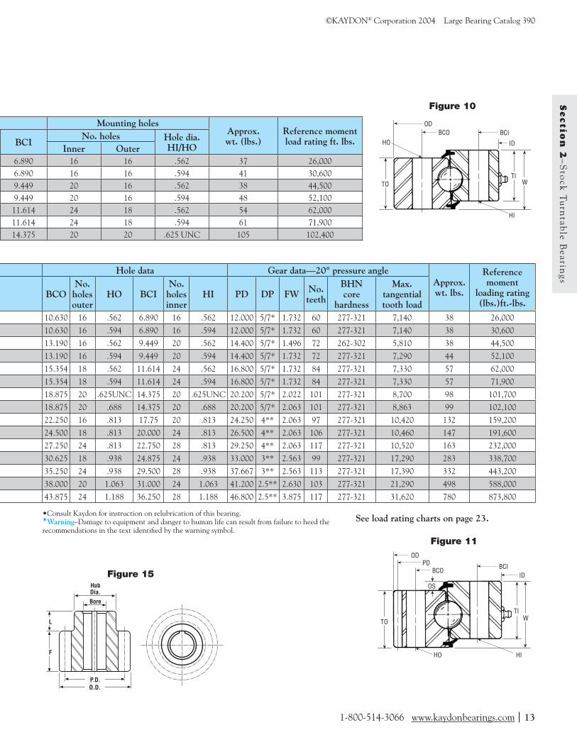
Table 1—Non geared MT Series (Figure 10)
Table 2—External gear MT Series (Figure 11)
KaydonP/N
ReferenceNo.
Outline dimensions (inches)
OD ID W TO TI OS
MTE-145 T7-9E1 12.286 5.709 1.968 1.732 1.732 .236
MTE-145X T7-9E3 12.286 5.709 1.968 1.732 1.732 .236
MTE-210• T7-11E1 14.686 8.268 1.575 1.496 1.496 .079
MTE-210X T7-11E9 14.686 8.268 1.968 1.732 1.732 .236
MTE-265 T7-14E3 17.086 10.433 1.968 1.732 1.732 .236
MTE-265X T7-14E14 17.086 10.433 1.968 1.732 1.732 .236
MTE-324 T8-17E 20.486 12.750 2.062 2.022 2.022 .040
MTE-324X T8-17E28 20.486 12.770 2.375 2.063 2.063 .312
MTE-415 T8-20E5 24.650 16.250 2.375 2.063 2.063 .312
MTE-470 T8-22E10 26.900 18.50 2.375 2.063 2.063 .312
MTE-540 T8-25E1 29.650 21.250 2.375 2.063 2.063 .312
MTE-590 T10-28E1 33.534 23.125 2.875 2.563 2.563 .312
MTE-705 T10-32E3 38.201 27.750 2.875 2.563 2.563 .312
MTE-730 T12-35E3 41.850 28.750 3.250 2.880 2.880 .375
MTE-870 T14-40E6 47.444 34.250 4.250 3.875 3.875 .375
Table 2A—Mating Pinions for MT-Series Bearings (Figure 15)
KaydonP/N
Pinion number
No.of
teeth
Diametral pitch
Face(F)
Hublength
(L)
Pitchdia.
Outerdia.
Hubdia.
Stockbore
SquareKeyway
MTE-145 thru MTE-324 39201001 17 5/7 2.250 3.125 3.400 3.686 2.906 1.000 .250
MTE-415 thru MTE-540
39200001 39200002
1417
44
2.0002.000
.88
.883.5004.250
3.9004.650
2.8803.630
1.0001.000
MTE-590 thru MTE-705
39200003 39200004
1417
33
2.0002.000
.88
.884.667 5.667
5.2006.200
3.8804.880
1.2501.250
Tolerances Ref. Ref. Ref. Ref. ±.000-.010 Ref. ±.002
-.000
1-800-514-3066 www.kaydonbearings.com|13
©KAYDON® Corporation 2004 Large Bearing Catalog 390 S
ectio
n 2
–S
tock
Tu
rntab
le Bearin
gs
See load rating charts on page 23.
Figure 10
Figure 11
ID
TO WTI
BCIBCOOD
HI
HO
ID
TO WTI
BCIBCO
OD
HI
OS
PD
HO
•Consult Kaydon for instruction on relubrication of this bearing.★Warning–Damage to equipment and danger to human life can result from failure to heed the recommendations in the text identifi ed by the warning symbol.
Hub Dia.Bore
L
F
O.D.P.D.
Figure 15
Mounting holesApprox.wt. (lbs.)
Reference moment load rating ft. lbs.BCI
No. holes Hole dia.HI/HOInner Outer
6.890 16 16 .562 37 26,0006.890 16 16 .594 41 30,6009.449 20 16 .562 38 44,5009.449 20 16 .594 48 52,10011.614 24 18 .562 54 62,00011.614 24 18 .594 61 71,90014.375 20 20 .625 UNC 105 102,400
Hole data Gear data—20° pressure angleApprox.wt. lbs.
Referencemoment
loading rating(lbs.)ft.-lbs.
BCONo.holesouter
HO BCINo.holesinner
HI PD DP FW No. teeth
BHNcore
hardness
Max.tangential tooth load
10.630 16 .562 6.890 16 .562 12.000 5/7* 1.732 60 277-321 7,140 38 26,000
10.630 16 .594 6.890 16 .594 12.000 5/7* 1.732 60 277-321 7,140 38 30,600
13.190 16 .562 9.449 20 .562 14.400 5/7* 1.496 72 262-302 5,810 38 44,500
13.190 16 .594 9.449 20 .594 14.400 5/7* 1.732 72 277-321 7,290 44 52,100
15.354 18 .562 11.614 24 .562 16.800 5/7* 1.732 84 277-321 7,330 57 62,000
15.354 18 .594 11.614 24 .594 16.800 5/7* 1.732 84 277-321 7,330 57 71,900
18.875 20 .625UNC 14.375 20 .625UNC 20.200 5/7* 2.022 101 277-321 8,700 98 101,700
18.875 20 .688 14.375 20 .688 20.200 5/7* 2.063 101 277-321 8,863 99 102,100
22.250 16 .813 17.75 20 .813 24.250 4** 2.063 97 277-321 10,420 132 159,200
24.500 18 .813 20.000 24 .813 26.500 4** 2.063 106 277-321 10,460 147 191,600
27.250 24 .813 22.750 28 .813 29.250 4** 2.063 117 277-321 10,520 163 232,000
30.625 18 .938 24.875 24 .938 33.000 3** 2.563 99 277-321 17,290 283 338,700
35.250 24 .938 29.500 28 .938 37.667 3** 2.563 113 277-321 17,390 332 443,200
38.000 20 1.063 31.000 24 1.063 41.200 2.5** 2.630 103 277-321 21,290 498 588,000
43.875 24 1.188 36.250 28 1.188 46.800 2.5** 3.875 117 277-321 31,620 780 873,800

RK Series (inch series) Bearing Selection Data Standard Tolerances
Pre-engineered turntable bearings from stock
Kaydon’s RK-Series bearings provide a cost effective solution for applications such as small cranes, booms, and lifts; aerial towers and ladders; industrial positioners and rotary tables; rotating displays; robotics; material handling equipment and conveyors.
Standard bolt holes make mounting easy. Available in sizes up to 48" O.D. with internal gear, external gear, and non-geared confi gurations. For moment loads to 140,000 ft.-lbs. Matching pinions also from stock.
★Warning–Damage to equipment and danger to human life can result from failure to heed the recommen-dations in the text identifi ed by the warning symbol.
Table 5A—Mating Pinions for RK-Series Bearings (Figure 15)
No. Hub Kaydon Pinion of Diametral Face length Pitch Outer Hub Stock
P/N No. teeth pitch (F) (L) dia. dia. dia. bore
RK6-16 thru 39200001 14 4 2.000 .88 3.500 3.900 2.880 1.000 RK6-29 39200002 17 4 2.000 .88 4.250 4.650 3.630 1.000 RK6-33 thru 39200003 14 3 2.000 .88 4.667 5.200 3.880 1.250 RK6-43 39200004 17 3 2.000 .88 5.667 6.200 4.880 1.250 Tolerances Ref. Ref. Ref. Ref. +.000 Ref. +.002 -.000 -.000
14 |www.kaydonbearings.com 1-800-514-3066
Large Bearing Catalog 390 ©KAYDON® Corporation 2004S
ecti
on
2–
Sto
ck T
urn
tab
le B
eari
ngs Kaydon
P/NWeight
lbs.
Outline dimensions (inches)
OD CO LO LI CI ID BCO
RK6-16P1Z 58 20.390 17.870 16.220 16.140 14.490 11.970 19.250RK6-22P1Z 76 25.510 22.990 21.340 21.260 19.610 17.090 24.380RK6-25P1Z 89 29.450 26.930 25.280 25.200 23.550 21.030 28.380RK6-29P1Z 104 33.390 30.870 29.220 29.140 27.490 24.970 32.250RK6-33P1Z 118 37.320 34.800 33.150 33.070 31.420 28.900 36.250RK6-37P1Z 132 41.260 38.740 37.090 37.010 35.360 32.840 40.130RK6-43P1Z 153 47.170 44.650 43.000 42.920 41.270 38.750 46.000
Tolerances ±.040 ±.000 -.080 Ref. Ref. ±.080
-.000 ±.040
Table 3—Non geared RK Series (Figure 12)
Table 4—Internal geared RK Series (Figure 13)
KaydonP/N
Weightlbs.
Outline dimensions (inches) Mounting holes
OD CO LO LI ID BCO No. holesBCO BCI
RK6-16N1Z 65 20.390 17.870 16.220 16.140 12.850 19.250 8 14.880RK6-22N1Z 90 25.510 22.990 21.340 21.260 17.600 24.380 10 19.630RK6-25N1Z 106 29.450 26.930 25.280 25.200 21.600 28.380 12 23.630RK6-29N1Z 121 33.390 30.870 29.220 29.140 25.600 32.250 15 27.630RK6-33N1Z 148 37.320 34.800 33.150 33.070 29.133 36.250 18 31.500RK6-37N1Z 165 41.260 38.740 37.090 37.010 33.133 40.130 18 35.500RK6-43N1Z 188 47.170 44.650 43.000 42.920 39.133 46.000 18 41.500
Tolerances ±.040 ±.000 -.080 Ref. Ref. ±.030
-.000
Table 5—External geared RK Series (Figure 14)
KaydonP/N Weight lbs.
Outline dimensions (inches) Mounting holes
OD LO LI CI ID BCO No. holesBCO BCI
RK6-16E1Z 72 19.900 16.220 16.140 14.490 11.970 18.000 8 13.130RK6-22E1Z 96 25.150 21.340 21.260 19.610 17.090 23.250 12 18.130RK6-25E1Z 115 29.150 25.280 25.200 23.550 21.030 27.250 15 22.130RK6-29E1Z 128 32.900 29.220 29.140 27.490 24.970 31.000 18 26.130RK6-33E1Z 152 37.200 33.150 33.070 31.420 28.900 35.000 18 30.000RK6-37E1Z 172 41.200 37.090 37.010 35.360 32.840 38.880 18 34.000RK6-43E1Z 189 46.867 43.000 42.920 41.270 38.750 44.630 20 39.880
Tolerances ±.030-.000 Ref Ref ±.000
-.080 ±.040

Matching pinions available from stock. See Table 5A.
Matching pinions available from stock. See Table 5A.
See load rating charts on page 23.
Figure 12
1.811 ref
.470
Inside dia. (ID)
.090 max. rad.
±.040
Inner bolt circle (BCI)Inside land (LI)
Outer circle (CO)
.688 dia. throughequally spaced
Inner circle (CI)Outside land (LO)
Outer bolt circle (BCO)Outside diameter (OD)
.090 max. rad.
.470±.040
1.102ref
1.811ref
2.205±.040
.688 dia. throughequally spaced
Figure 13
1.811 ref
Gear inside dia. (ID)Gear pitch dia. (PD)
Inner bolt circle (BCI)Inside land (LI)
.500-13 UNC-2B
.750 min. full thread depth equally spaced
Outside land (LO)Outer bolt circle (BCO)
Outside diameter (OD)
.090 max. rad.
.470±.040
1.811ref
2.205±.040
.688 dia. throughequally spaced
Outer circle (CO)
.708 ref
Figure 14
1.811ref
Gear pitch dia. (PD)Gear outside dia. (OD)
Inner bolt circle (BCI)Inside land (LI)
.500-13 UNC-2B
.750 min. full thread depth equally spaced
Outside land (LO)
.090 max. rad.
.470±.040
.688 dia. throughequally spaced
1.811ref
2.205±.040
Inner circle (CI)
Outer bolt circle (BCO)
Inside dia. (ID)
Hub Dia.Bore
L
F
O.D.P.D.
Figure 15
1-800-514-3066 www.kaydonbearings.com|15
©KAYDON® Corporation 2004 Large Bearing Catalog 390 S
ectio
n 2
–S
tock
Tu
rntab
le Bearin
gs
Mounting holesNo. holes
BCO BCI No. holes BCI
8 13.130 1212 18.130 1512 22.130 1815 26.130 1818 30.000 1818 34.000 2018 39.880 24
Gear data—20° stub involuteNo. holes
BCI PD Diametralpitch
No.teeth
Max. tangentialtooth load (lbs.)
Circle tooththickness
12 13.250 4 53 6810 .3877/.377715 18.000 4 72 6460 .3877/.377718 22.000 4 88 6430 .3877/.377718 26.000 4 104 6320 .3877/.377718 29.667 3 89 8520 .5186/.508620 33.667 3 101 8440 .5186/.508624 39.667 3 119 8340 .5186/.5086
Gear data—20° stub involute
No. holesBCI PD Diametral
pitchNo.teeth
Max. tangentia tooth load (lbs.)
Circle tooththickness
12 19.500 4 78 5550 .3877/.377715 24.750 4 99 5650 .3877/.377718 28.750 4 115 5690 .3877/.377718 32.500 4 130 5760 .3877/.377718 36.667 3 110 7590 .5186/.508620 40.667 3 122 7640 .5186/.508624 46.333 3 139 7680 .5186/.5086

Custom Four-Point ContactBearing Selection Data
The unique “Gothic Arch” raceway design of four-point contact ball bear-ings provides an exceptional means of handling combined axial, radial and moment loading. The applications for these bearings are unlimited, ranging from heavy-duty cranes to machine tool turntables to advanced medical imag-ing equipment. Kaydon bearings have been manufactured with up to 10 million pounds-feet of moment load capacity.
Listed below is a sampling of the many custom-designed four-point contact ball bearings produced by Kaydon. One of these bearings may offer a pre-engineered design solution to your specifi c applica-tion requirements.
Many other custom designs are available. Through preloading and close tolerance machining, extreme high precision levels can be maintained for these large-diam-eter bearings. Kaydon engineers will be happy to review your application and make specifi c design recommendations.
Table 6—Non geared four-point (Figure 16)
Outline dimensions (inches) Hole Model Kaydon No. No. P/N OD ID W TO TI DI DO BCO holes HO outer T4-13P1 12062 15.790 9.170 1.580 1.228 1.228 13.64 11.79 14.880 8 .562
Table 7—Internal geared four-point (Figure 17)
Outline dimensions (inches) Hole data Model Kaydon No. No. P/N OD ID W TO TI CI BCO holes HO BCI outer T10-46N4 12496 51.120 39.760 3.560 3.120 2.690 41.620 49.125 24 1.063 43.000 T14-49N1 12131 54.375 41.280 5.000 3.875 4.625 43.000 52.500 22 .938 45.250 T20-95N1 09722 102.500 85.360 7.440 6.780 5.660 88.380 99.803 16 1.313 91.142
*UNF **UNC***Fellow stub★Warning–Damage to equipment and danger to human life can result from failure to heed the recommen-dations in the text identifi ed by the warning symbol.
Table 8—External geared four-point (Figure 18)
Outline dimensions (inches) Hole data Model Kaydon No. No. P/N OD ID W TO TI CO BCO holes HO BCI outer T8-39E4 12246 42.640 35.157 3.234 2.905 2.875 41.024 39.960 30 5/8-11 36.300 T10-20E2 12134 25.650 16.250 3.500 3.250 2.875 — 23.250 18 .781 17.625 T10-24E1 12343 30.171 18.875 3.500 3.188 2.625 — 27.625 36 .781 20.750 T14-18E2 11457 23.650 12.880 3.440 3.190 3.190 — 21.250 18 3/4-16 14.375 T14-22E4 12037 28.400 17.130 3.440 3.190 3.190 — 25.380 18 .781 18.630 T14-24E6 12070 29.887 19.125 3.625 3.250 3.250 — 27.375 30 3/4-10 20.625 T18-44E1 11736 52.800 36.950 4.750 4.375 4.375 50.655 48.250 30 1.313 39.375 T24-65E1 11729 74.800 55.875 6.375 6.000 6.000 72.625 70.250 45 1.313 58.500 T24-65E4 11311 75.800 53.875 6.500 6.000 6.000 66.990 70.250 52 1-1/2-6 58.500 T24-89E2 11930 98.800 78.400 6.625 6.000 6.000 98.000 94.250 72 1-1/2-6 82.500 T24-75E3 12198 85.067 66.750 7.120 6.500 6.620 82.120 80.125 30 1.313 69.250 T24-89E1 11277 98.800 78.400 6.625 6.000 6.000 98.000 94.250 72 1-1/2-6 82.500
16 |www.kaydonbearings.com 1-800-514-3066
Large Bearing Catalog 390 ©KAYDON® Corporation 2004S
ecti
on
3–
Oth
er P
rod
uct
s
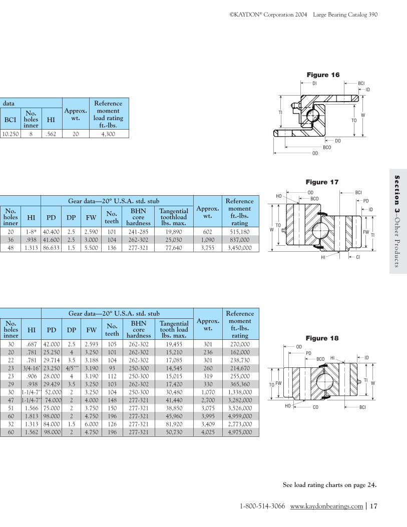
data Reference No. Approx. moment
BCI holes HI wt. load rating inner ft.-lbs.
10.250 8 .562 20 4,300
Gear data—20° U.S.A. std. stub Reference
No. BHN Tangential Approx. momentholes HI PD DP FW No. core toothload wt. ft.-lbs.inner teeth hardness lbs. max. rating
20 1-8* 40.400 2.5 2.590 101 241-285 19,890 602 515,180 36 .938 41.600 2.5 3.000 104 262-302 25,030 1,090 837,000 48 1.313 86.633 1.5 5.500 136 277-321 77,640 3,755 3,450,000
Gear data—20° U.S.A. std. stub Reference
No. BHN Tangential Approx. momentholes HI PD DP FW No. core tooth load wt. ft.-lbs.inner teeth hardness lbs. max. rating
30 .687 42.000 2.5 2.593 105 262-302 19,455 301 270,000 20 .781 25.250 4 3.250 101 262-302 15,210 236 162,000 22 .781 29.714 3.5 3.188 104 262-302 17,085 301 238,730 23 3/4-16* 23.250 4/5*** 3.190 93 250-300 14,545 260 214,670 23 .906 28.000 4 3.190 112 250-300 15,015 319 255,000 29 .938 29.429 3.5 3.250 103 262-302 17,420 330 365,360 30 1-1/4-7** 52.000 2 3.250 104 250-300 30,480 1,070 1,338,000 47 1-1/4-7** 74.000 2 4.000 148 277-321 41,440 2,700 3,282,000 51 1.566 75.000 2 3.750 150 277-321 38,850 3,075 3,526,000 60 1.813 98.000 2 4.750 196 277-321 45,960 3,995 4,959,000 32 1.313 84.000 1.5 6.000 126 277-321 81,920 3,409 2,773,000 60 1.562 98.000 2 4.750 196 277-321 50,730 4,025 4,975,000
Figure 18
Figure 17
Figure 16
W
ID
TO
TIFW
PD
BCIBCO
OD
HI
HO
CI
TO
ID
FW WTI
PD
BCI
BCO
OD
HO
HI
CO
ID
TI WTO
BCI
BCOOD
DI
DO
See load rating charts on page 24.
1-800-514-3066 www.kaydonbearings.com|17
©KAYDON® Corporation 2004 Large Bearing Catalog 390 S
ectio
n 3
–O
ther P
rod
ucts
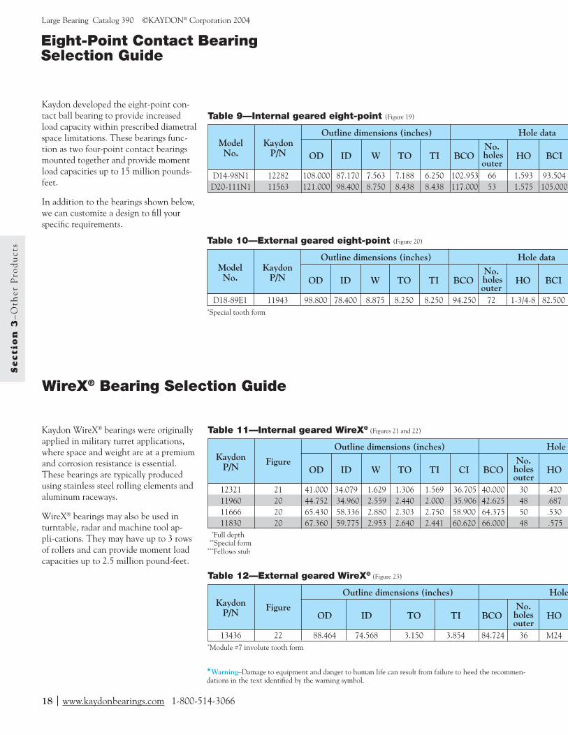
Eight-Point Contact Bearing Selection Guide
Kaydon developed the eight-point con-tact ball bearing to provide increased load capacity within prescribed diametral space limitations. These bearings func-tion as two four-point contact bearings mounted together and provide moment load capacities up to 15 million pounds-feet.
In addition to the bearings shown below, we can customize a design to fi ll your specifi c requirements.
WireX® Bearing Selection Guide
Kaydon WireX® bearings were originally applied in military turret applications, where space and weight are at a premium and corrosion resistance is essential. These bearings are typically produced using stainless steel rolling elements and aluminum raceways.
WireX® bearings may also be used in turntable, radar and machine tool ap-pli-cations. They may have up to 3 rows of rollers and can provide moment load capacities up to 2.5 million pound-feet.
Table 10—External geared eight-point (Figure 20)
Outline dimensions (inches) Hole data Model Kaydon No. No. P/N OD ID W TO TI BCO holes HO BCI outer D18-89E1 11943 98.800 78.400 8.875 8.250 8.250 94.250 72 1-3/4-8 82.500 *Special tooth form
Table 11—Internal geared WireX® (Figures 21 and 22)
Outline dimensions (inches) Hole d Kaydon No. P/N
Figure OD ID W TO TI CI BCO holes HO
outer 12321 21 41.000 34.079 1.629 1.306 1.569 36.705 40.000 30 .420 11960 20 44.752 34.960 2.559 2.440 2.000 35.906 42.625 48 .687 11666 20 65.430 58.336 2.880 2.303 2.750 58.900 64.375 50 .530 11830 20 67.360 59.775 2.953 2.640 2.441 60.620 66.000 48 .575 *Full depth **Special form***Fellows stub
★Warning–Damage to equipment and danger to human life can result from failure to heed the recommen-dations in the text identifi ed by the warning symbol.
Table 12—External geared WireX® (Figure 23)
Outline dimensions (inches) Hole Kaydon No. P/N
Figure OD ID TO TI BCO holes HO
outer 13436 22 88.464 74.568 3.150 3.854 84.724 36 M24 *Module #7 involute tooth form
Table 9—Internal geared eight-point (Figure 19)
Outline dimensions (inches) Hole data Model Kaydon No. No. P/N OD ID W TO TI BCO holes HO BCI outer D14-98N1 12282 108.000 87.170 7.563 7.188 6.250 102.953 66 1.593 93.504 D20-111N1 11563 121.000 98.400 8.750 8.438 8.438 117.000 53 1.575 105.000
18 |www.kaydonbearings.com 1-800-514-3066
Large Bearing Catalog 390 ©KAYDON® Corporation 2004S
ecti
on
3–
Oth
er P
rod
uct
s

Gear data—20° pressure angle Reference
No. BHN Tangential Approx. momentholes HI PD DP FW No. core tooth load wt. lbs. loadinner teeth hardness lbs. max. ft.-lbs.
60 1.812 98.000 2 4.750 196 277-321 49,680 5,580 7,900,000
data Gear data—20° pressure angle No. Approx.
BCI holes HI PD DP FW No. Ring wt. lbs. inner teeth material
35.750 12 3/4-16 34.200 10/12*** .750 342 Steel 10537.375 64 .687 35.200 5* 2.000 176 Alum. 150
61.250 48 1/2-20 58.500 10** 1.500 585 Alum. 31061.750 48 1/2-13 60.000 8** 1.939 480 Alum. 182
data Gear data—20° pressure angle No. Approx.
BCI holes HI PD DP FW No. Ring wt. lbs. inner teeth material
77.205 29 1.024 88.189 3.629* 3.150 320 Alum. 615
Gear data—20° pressure angle Reference
No. BHN Tangential Approx. momentholes HI PD DP FW No. core tooth load wt. lbs. loadinner teeth hardness lbs. max. ft.-lbs.
66 1.593 87.874 1.411* 4.130 124 277-321 73,760 5,170 6,900,000 72 1.575 100.000 1.25* 6.000 125 277-321 107,130 7,610 14,000,000
Figure 19
Figure 20
Figure 21
Figure 22
Figure 23
TO
ID
FW WTI
PDBCI
BCOOD
TO
ID
FW
WTI
PD
BCI
BCOOD
HI
HO
W
ID
TO
TIFW
PDBCIBCO
OD
HI
HO
CI
W
ID
TOTI
FW
PD
BCI
BCOOD
HI
HOCI
TO
ID
TI
BCI
BCO
OD
HO
See load rating charts on page 24.
1-800-514-3066 www.kaydonbearings.com|19
©KAYDON® Corporation 2004 Large Bearing Catalog 390 S
ectio
n 3
–O
ther P
rod
ucts

KH Series bearings are designed to pro-vide precise positioning and stopping, with consistent repeatability, in applica-tions where rotation is constant, inter-mittent or oscillating. They are the ideal bearing for advanced rotary index tables or any design where the bearing will interface with other precision mechani-cal components.
The KH Series bearing’s unique 4-point contact ball geometry enables one bearing to handle simultaneous radial,
axial and moment loading. An internal diametral preload provides greater stiff-ness and minimum free play. And unlike conventional air bearings, Kaydon KH Series will not lock up in the presence of off-center loads.
Available in 3 popular pitch diameters, in geared and non-geared versions, Series KH bearings feature a low profi le to permit larger work areas above the index table.
KH Series Pre-engineered high precision bearing assemblies
Figure 24 Figure 25
Gear pitch dia. (G.P.D.)External gear (G.O.D.)
±.050
Land (P.L.I.) 500-13 UNC-2B.750 min. fullthread depth
I.D.
1.250 ref.
±.0302.000
Bolt circle (B.C.I.)Ref. ball pitch (P.D.)
Land (P.L.O.)Bolt circle (B.C.O.)
±.050O.D.
500-13 UNC-2B.750 min. fullthread depth
±.0302.000
.250 min. pilot depth
±.0102.500
Dynamic Intermittent Kaydon
Axial Moment Axial Moment
P/N (lbs.) (lbs-ft.) (lbs.) (lbs-ft.)
KH-166 36,000 20,500 82,850 45,250 KH-225 40,000 30,500 115,200 56,000 KH-275 43,000 39,600 142,000 75,050
Table 15A—Designed for both dynamic and intermittent loads
Note: Dynamic-L10 capabilities based on million revolutions. Values do not apply simultaneously.Intermittent-Individual capacity limits for maximum loading when normal mode of operation is an intermittent load application and rotation.
20 |www.kaydonbearings.com 1-800-514-3066
Large Bearing Catalog 390 ©KAYDON® Corporation 2004S
ecti
on
3–
Oth
er P
rod
uct
s
Table 14—Non geared KH Series (Figure 24)
Table 15—Geared KH Series (Figure 25)
KaydonP/N
Outline dimensional data (inches) Land diameters Hole dataNo. lube
holes
Approx. assembly
lbs.PD ID OD PLI PLO No. holes inner
No. holes outer BCI BCO
KH-166P 16.600 12.750 20.500 16.375 16.875 20 20 14.375 18.875 1 106KH-225P 22.500 18.500 26.700 22.250 22.750 18 18 20.500 24.500 1 150KH-275P 27.500 23.500 31.700 27.250 27.750 24 24 25.500 29.500 1 185
Full depth involute gear 6 D.P., 20° pressure angle AGMA quality 8
KaydonP/N G.O.D. G.P.D. No. of
teethCircular tooth
thicknessAllowance
for backlashApprox.
assembly lbs.KH-166E 20.500 20.167 121 .2618/.2568 .000-.005 100KH-225E 26.667 26.333 158 .2618/.2568 .000-.005 142KH-275E 31.667 31.333 188 .2618/.2568 .000-.005 175

Tight defl ection and tilt tolerances give KH Series bearings their precision
KH Series bearings are often used in applications where the position of a rotating part relative to the stationary structure is critical. The axis of rotation can be displaced from its true position in three ways-radially, axially, and angu-larly. These deviations are referred to as radial defl ection, axial defl ection, and tilt (angular rotation).
The following three tables show stiffness of standard KH Series bearings. If your application requires increased stiffness, Kaydon can often supply a stiffer bearing in the same envelope dimensions. Call us at (800) 514-3066.
0.0014
0.0012
0.0010
0.0008
0.0006
0.0004
0.0002
0
Rad
ial D
efle
ctio
n (i
n.)
Radial Loads (lbs.)0 1000 2000 3000 4000 5000 6000 7000 8000
KH166KH225KH275
.0007
.0006
.0005
.0004
.0003
.0002
.0001
.0000
Moment Loads (in.-lbs.)0 5,0000 100,000 150,000 200,000 250,000 300,000 350,000 400,000 450,000
KH166KH225KH275
Tilt
of A
xis (
radi
ans)
.0040
.0035
.0030
.0025
.0020
.0015
.0010
.0005
.0000
Axi
al D
efle
ctio
n (i
n.)
Axial Loads (lbs.)0 10,000 20,000 30,000 40,000 50,000 60,000
KH166KH225KH275
Materials of construction and technical data
Rolling elements–Chrome steel hardened to Rockwell C 60 minimum.
Ball paths (raceways)–Selectively hardened for maximum obtainable bearing capacity. Four-point internal design permits ac-ceptance of combination axial, radial, and moment loads.
Geared and ungeared rings–Rolled high carbon steel forgings quenched and tempered to 262 BHN minimum
Gears–Involute Stub, 20° pressure angle, AGMA quality 8
Seals–Nitrile rubber seals provide positive contact for retention of lubrication and exclusion of contaminants
Lubrication–Multi-purpose lithium-based, NLGI No. 1 E.P. grease
Figure 25A—Radial Defl ection
Figure 25C—Tilt of Axis
Figure 25B—Axial Defl ection
1-800-514-3066 www.kaydonbearings.com|21
©KAYDON® Corporation 2004 Large Bearing Catalog 390 S
ectio
n 3
–O
ther P
rod
ucts

Special Bearing Capabilities
In addition to the more standard bear-ings shown on the preceding pages, Kaydon has extensive experience in the design and manufacture of customized or special bearings and assemblies. The ball and roller bearings shown below are only a sampling of our custom capabilities.
Biangular roller bearings generally pro-vide higher stiffness and lower turning torques than four-point contact ball bearings with equivalent load capacities or dimensional envelopes.
Figure 27The standard biangular bearing has been applied in a variety of wind energy, radar and military turret applications.
Figure 30This aluminum race bearing with nonmetallic balls was originally developed to provide light weight and corrosion resistance in a lightly load-ed military turret. Similar bearings are used in medical equipment applications where the envi-ronment does not allow for grease lubrication. A wide variety of ball materials can be used.
Figure 28The lightweight biangular bearing is made from steel and was originally designed for use as a turret bearing on a steel-hulled military vehicle.
Figure 31This three-row roller bearing is used on a large crane slewing ring and provides a high degree of stiffness, generally interchangeable with an eight-point contact ball bearing.
Figure 29The WireX® single-row biangular bearing shown provides a larger rolling element—and resultant higher load capacity—than a two-row WireX® bearing with the same cross-selectional area. As with the bearings shown on Pages 18-19, the aluminum races and stainless rollers and wires provide light weight and corrosion resistance.
Figure 32This military turret bearing is a thin-section large diameter bearing with custom options such as fl anges and internal gears cut on the outer race. By adding these options to the bearing, a number of individual parts can be eliminated, simplifying assembly and resulting in lower total system cost.
5.000
78.00082.667
84.00068.000
64.500
6.0004.500
.625
61.25055.000
62.500
1.9382.000
57.000
.900
2.559
42.62544.752
2.4402.000
2.390
34.96037.375
1.629
40.00041.000
1.265.750 .939
35.75036.690
34.20034.079
1.569 9.563
149.500161.750
164.750144.000142.400
8.196
8.500 3.688
108.000109.500
106.250
103.750
4.562
1.406
100.640101.000
103.000
3.031
102.448100.500
22 |www.kaydonbearings.com 1-800-514-3066
Large Bearing Catalog 390 ©KAYDON® Corporation 2004S
ecti
on
3–
Oth
er P
rod
uct
s

Load Rating ChartsA
xial
load
(lb
s. x
1,00
0,00
0)
.4
.3
.2
.1
050 10 15 20
Moment load (ft.-lbs. x 10,000)
A B C D E F G H I
A–MT-145B–MT-145XC–MT-210D–MT-210XE–MT-265
LegendF–MT-265XG–MT-324H–MT-325I –MT-415
Axi
al lo
ad (
lbs.
x 1,
000,
000)
1.6
1.2
.8
.4
010 5 8 10
Moment load (ft.-lbs. x 100,000)
J K L
J–MT-470K–MT-540L–MT-590
LegendM–MT-705N–MT-730O–MT-870
1.51.41.3
1.11.0.9
.7
.6
.5
.3
.2
.1
2 3 4 6 7 9
M N O
MT-Series ratings apply to either MTE or MTO Series
Axi
al lo
ad (
lbs.
x 10
00)
200
150
100
50
0200 40 60 80
Moment load (ft.-lbs. x 1000)
A B C D E F G
A–RK6-16B–RK6-22C–RK6-25D–RK6-29
LegendE–RK6-33F–RK6-37G–RK6-43
100 120 140
Axi
al lo
ad (
lbs.
x 1,
000,
000)
4.0
3.0
2.0
1.0
050 25 40 50
Moment load (ft.-lbs. x 100,000)
A B C
A–T10-46B–T14-49C–T20-95
Legend
10 15 20 30 35 45
3.5
2.5
1.5
0.5
Internal gear4-point contact
Figure 33 Figure 34
Figure 35 Figure 36
RK-Series
1-800-514-3066 www.kaydonbearings.com|23
©KAYDON® Corporation 2004 Large Bearing Catalog 390 S
ectio
n 4
–L
oad
Ratin
g Ch
arts

24 |www.kaydonbearings.com 1-800-514-3066
Axi
al lo
ad (
lbs.
x 1,
000,
000)
.80
.60
.40
.20
00
Moment load (ft.-lbs. x 10,000)
C
A–T10-20B–T14-18C–T10-24
LegendD–T14-22E–T8-39
.75
.70
.65
.55
.50
.45
.35
.30
.25
.15
.10
.05 DE
5 25 40 5010 15 20 30 35 45
BA
External gear4-point contactSee pages 16-17.
Axi
al lo
ad (
lbs.
x 1,
000,
000)
4.0
3.0
2.0
1.0
050 25 40 50
Moment load (ft.-lbs. x 100,000)
A B C
10 15 20 30 35 45
3.5
2.5
1.5
0.5
A–T14-24B–T18-44C–T24-75
LegendD–T24-65E1E–T24-65E5F–T24-89
D E F
External gear4-point contactSee pages 16-17.
Axi
al lo
ad (
lbs.
x 1,
000,
000)
8.0
6.0
4.0
2.0
020 10 16 20
Moment load (ft.-lbs. x 1,000,000)
A B C
A–D14-98B–D18-89C–D20-111
Legend
4 6 8 12 14 18
7.0
5.0
3.0
1.0
8-point contactSee pages 18-19.
Figure 37 Figure 38
Figure 39
Large Bearing Catalog 390 ©KAYDON® Corporation 2004S
ecti
on
4–
Lo
ad R
atin
g C
har
ts

1-800-514-3066 www.kaydonbearings.com|25
Allo
wab
le m
ount
ing
defle
ctio
n (i
n. in
90°
arc
)
.150
200 40 60Bearing pitch diameter (in.)
80 100 120 140 160 180
.130
.110
.090
.070
.050
.030
.0101” ball
1-1/2” ball
2” ball
2-1/2” ball
3” ball
3-1/2” ball
Part I—Design Considerations (For Guidance of the Equipment Designer)
Mounting structure
Most designs are necessarily a compro-mise from the ideal to the practical. The design of mountings for large multiload bearings is no exception. Several condi-tions, however, must be satisfi ed by the mounting structures above and below the bearing, in order to give good bearing life and performance. These conditions are stiffness, fl atness, hole location accuracy, protection, access for maintenance, and attachment method.
Stiffness
The ideal bearing mounting would be absolutely rigid, but mobile equipment is by its very nature fl exible and thus elastic defl ections will occur. However, distor-tions can be held to tolerable levels if the shape of the main structural members above and below the bearing are gener-ally in the form of a cylinder whose outer diameter is equal to or slightly larger than the bearing ring to which they are attached. An example is the fl anged drums commonly used on crawler trucks.
Figure 40 has been prepared to show the maximum allowable defl ections ball bearings can withstand and still function properly. Defl ection must be gradual. Avoid short, stiff sections in the mount-ing as these can adversely affect the loading pattern of the rolling elements by causing extremely high loads between a few elements and the raceways. They also have a similarly adverse effect on bolt loads. In addition, excessive turn-ing torque may result, causing high gear tooth loads.
Installation and Care of Kaydon Turntable Bearings
NOTE: These charts refer to ball bearings. For roller bearings, consult Kaydon for allowable stiffness and fl atness.
Allo
wab
le m
ount
ing
surf
ace
out-
of-f
latn
ess
(in.
in 9
0° a
rc)
200 40 60Bearing pitch diameter (in.)
80 100 120 140 160 180
.060
.050
.040
.030
.020
.010
2-1/2” ball
3-1/2” ball
0
3” ball
2” ball
1-1/2” ball
1” ball
Figure 40—Allowable mounting defl ection (circumferential)
Figure 41—Allowable mounting out-of-fl atness (circumferential)
©KAYDON® Corporation 2004 Large Bearing Catalog 390 S
ectio
n 5
–In
stallation
and
Main
tenan
ce

26 |www.kaydonbearings.com 1-800-514-3066
Flatness
Bearing mounting surfaces must be machined fl at after all welding and stress relief treatment on the structures is com-plete. If subsequent welding is neces-sary, it must be done in such a manner that no distortion is experienced by the machined mounting surface. The allow-able degree of out-of-fl atness is shown in Figure 41. Out-of-fl atness like distortion, must be gradual.
Questions are often asked about shim-ming or grouting of mounting surfaces to compensate for excessive out-of-fl atness. While shimming is acceptable if done properly, most equipment builders fi nd it so diffi cult to control in production that it is more troublesome and costly than machining. Plastic grout has such a low modulus of elasticity that under cyclic loading mounting bolt fatigue failure can result. Thus, KAYDON STRONGLY RECOMMENDS AGAINST THE USE OF GROUTING WHEREVER CYCLIC THRUST AND MOMENT LOADS ARE EXPECTED.
Another consideration is the al-lowable deviation from a true plane in a radial direction (“dish”), which is more diffi cult to control in machining mount-ing surfaces. Table 16 shows allowable values for out-of-fl atness as machined and for defl ection under load.
Table 16
Hole location accuracy, pilots
Mounting holes and dowel holes, if any, must be within the true location toler-ances required to prevent distortion of the bearing due to interference. See the applicable drawing for the bearing toler-ances. Use of bearings as templates for transfer of hole location is permissible if care is taken not to distort thin section bearings. But bearings should never be used as drill jigs.
Pilots, if used, must be round and accur-ately sized so that they do not distort the bearing. Mounting hole location toler-ance must include any eccentricity of the hole pattern with pilot diameters.
Protection
In general, Kaydon bearings are de-signed to withstand all normal operating environments. However, if the upper structure does not provide complete cover for the upper bearing, a seal or shield should be added. Also, an external gear that would be exposed to very dirty conditions should be shrouded.
Shields and shrouds should be designed with cover doors, plugs, or other means of access to the bearing for the purposes discussed below.
Access for maintenance
Like all mechanical components on a machine, the bearing must be accessible so that it can be properly maintained. The following must be considered.★Mounting bolts require periodic check-ing and retightening. Access to every mounting bolt must be readily avail-able, or this maintenance item will be neglected and may result in mounting bolt failure.
Lubrication of Gear and Raceway is required and therefore convenient access to the gear and bearing grease fi ttings must be provided. Convenience is stressed because of the human element involved. It is best to add remote lines to the bearing so that it may be rotated as grease is introduced to the raceways.
The Taper Pin Retainer for the ball loading hole plug must be removed on rare occasions by qualifi ed personnel to inspect raceways or to replace rolling ele-ments or spacers. A hole, approximately 11/4 inches in diameter must be located in both upper and lower mounting struc-tures directly above and below the “Taper Pin Retainer,” so that it may be removed. (See Figure 42.)
★Attachment
The method of attachment of Kaydon bearings to the support structure signifi -cantly affects their design. The type, size, and quantity of fasteners must be determined if bolts will be used. If weld-ing is to be done, a decision must be made as to which race will be so attached and whether a “band” will be welded to the inner or outer diameter or a “ring” will be welded to one of the faces.
★Bolts
The preferred bolting arrangement is a full circle of equally spaced fasteners in through holes in both bearing races. This benefi ts both the bearing and the bolts. The bearing races are reinforced by the bolt pretension. The greater bolt length makes for more accurate and uniform pretension.
Figure 42—Access holes for loading hole plug
Allowable out-of-fl atness anddefl ection—radial (“dish”)
Out-of-fl atness Defl ection
Ball dia. inches per inches per
inches
radial inch of radial inch of mounting mounting surface surface 1 .0010 .0030 1-1/2 .0015 .0045 2 .0020 .0060 2-1/2 .0025 .0075 3 .0030 .0090 3-1/2 .0035 .0105
Large Bearing Catalog 390 ©KAYDON® Corporation 2004S
ecti
on
5–
Inst
alla
tio
n a
nd
Mai
nte
nan
ce

1-800-514-3066 www.kaydonbearings.com|27
★For three important reasons responsibil-ity for the quantity, size, and thread en-gagement of fasteners must be accepted by the equipment designer.
a. There is no universally accepted method of analyzing the forces imposed on the fasteners in a joint subjected to moment loading.
b. The stiffness and uniformity of the structures to which the bearing is attached have an extremely high degree of infl uence on the load in the fasteners. Only the equipment designer can control this.
c. The quality of the fasteners, the method of pretensioning, the hardness of the surfaces under the heads and the thread lubricant are other important factors over which the equipment manufacturer has control.
★This should be done with the advice and assistance of the supplier of the bolts because the quality of bolts varies widely as do the recommendations for methods of pretensioning and maintenance of pretension. Attention to such details as a head/body fi llet radius, thread form, as well as the more obvious freedom from cracks and other possibly fatal fl aws are very important to the safety of the equipment. The importance of adequate and uniform pretensioning is evident from the proliferation of and advances in devices offered for this purpose—ranging from turn of the nut indicator to preload indicating washers to torque wrenches with integral “yield” sensors to computer-ized torque wrenches to hydraulic bolt stretchers.
★At the least, Kaydon recommends the use of high strength bolts with coarse threads and hexagon heads, and heavy series nuts of equivalent strength. Also, recommended is the use of thread lubri-cant and hardened steel fl at, Belleville, or calibrated preload indicating washers. Use of lockwashers is NOT recommend-
ed when bolts are tensioned by torquing, because of the danger of undertensioning due to high friction torque.
For the protection of the equipment builder, specifi cations should require that the bolts carry not only the stan-dard SAE grade code but also a positive means of identifying the manufacturer.
★Welding
Of late, the attachment of bearings by welding has been limited on new appli-cations to unusual situations. These are best handled by working directly with the Kaydon Engineering Department to
Bolt Loading
To aid the designer, a method is presented here to calculate the approximate load on the heaviest loaded bolt. This method is based upon past experience and yields results that have proved satisfactory for most applications. It is analogous to the method Kaydon uses to determine the load in the heaviest loaded rolling element within a bearing.
However, for the reasons stated Kaydon makes no warranty, expressed or implied, regarding the adequacy of the bolts. The only certain way to determine the actual load is by testing, which is strongly recommended.
Bolt Load Factor of Safety
Rb = M x Ff
± Ft *Fs =
Bolt Proof Load Rating D x N N Rb
M = Moment load in pounds-inchesFf = Flexibility factor. Use 3 for bearings and support structures of average
stiffnessFt = Axial load in lbs.D = Bolt circle dia. in inchesN = total number of equally spaced boltsRb = Total load on heaviest loaded bolt in lbs.*Fs = Factor of safety of bolts. Recommended minimum value 3
Bolt Proof LoadCoarse Thread Series
S.A.E. Grade #8 and ASTM A 490 Proof ProofBolt Dia. Ins. Load Lbs. Bolt Dia. Ins. Load Lbs.1/2 ...........................................17,000 1 .............................................. 72,7005/8 ...........................................27,100 1-1/8 ........................................ 91,6003/4 ...........................................40,100 1-1/4 ...................................... 116,3007/8 ...........................................55,400 1-1/2 ...................................... 168,600
establish both the optimum design and the best welding procedures.
Gears
Kaydon offers integral gears as either straight or helical spur, and either inter-nal or external. Use of a 20° pressure angle is favored because of availability of standard cutters, but 14-1/2°, 25°, and special pressure angles can be furnished.
Selection
The machine designer will usually deter-mine the tooth size and form, working within the constraints of his application and basing his selection on his own
★See warranty, page 33.
©KAYDON® Corporation 2004 Large Bearing Catalog 390 S
ectio
n 5
–In
stallation
and
Main
tenan
ce

methods of calculation and past experi-ence. However, the commonly accepted Lewis equation may be used to determine the size of the gear.
L = SFY
P
L = Tangential Tooth Load
S = Allowable Bending Stress
Y = Tooth Form Factor (Table 17)
P = Diametral Pitch
F = Face Width
Allowable bending stress (S)
Allowable BendingCore Hardness Stress P.S.I.
241-285 BHN (23-30Rc) 34,000262-302 BHN (27-32Rc) 37,000277-321 BHN (29-34Rc) 40,000
The stresses given above are for maxi-mum or “Stall Torque” conditions. When shock factors are included in the load-ing, higher stresses may be used.
The “Stub” tooth form is often used in large gears. Economics is the main reason this tooth form is selected. It requires less material in the ring forging and less gear cutting time. The “Full Depth” tooth form provides a greater contact ratio, and consequently smooth-er operation but lower bending strength.
Surface hardening
Induction hardened gear teeth, with minimum surface hardness of 55 Rc should be considered when high tooth surface pressures constantly occur. An excavator or logger which sees a high rate of acceleration and a rapid decel-eration during a swing cycle would be typical of this condition.
A full root radius with root hardening is recommended when gear teeth are induction hardened. The tooth pattern and depth of hardness are critical.
Table 18
Case depth-induction hardened gears Diametral pitch Flank depth Root depth 4.00 .040 .030 3.50 .050 .035 3.00 .060 .040 2.50 .075 .050 2.00 .100 .070 1.75 .125 .080 1.50 .150 .100
Table 17
Tooth form factor (Y) No. 20° full 20°stub Internal gears of depth involute tooth Fellows stub tooth system 20°full depth teeth system system 4/5 5/7 6/8 system 12 .245 .311 .301 .349 .320 13 .261 .324 .317 .361 .336 14 .276 .339 .330 .374 .352 15 .289 .348 .339 .386 .361 16 .295 .361 .349 .396 .374 17 .302 .367 .358 .405 .383 18 .308 .377 .367 .411 .389 19 .314 .386 .374 .412 .399 20 .320 .393 .380 .424 .405 21 .327 .399 .386 .430 .411 22 .330 .405 .393 .437 .412 24 .336 .415 .402 .446 .427 26 .346 .424 .408 .455 .437 28 .352 .430 .418 .462 .443 .691 30 .358 .437 .424 .468 .449 .678 34 .371 .446 .437 .480 .461 .660 38 .383 .456 .440 .484 .468 .644 43 .396 .462 .452 .446 .480 .628 50 .408 .474 .462 .506 .490 .613 60 .421 .484 .471 .515 .499 .597 75 .434 .496 .484 .525 .509 .581 100 .446 .506 .496 .537 .521 .565 150 .459 .518 .509 .547 .534 .550 300 .471 .534 .525 .563 .550 .534 Use in Lewis Formula for P_________ 4 5 6
Therefore, a high degree of quality con-trol must be exercised to assure that the proper pattern is maintained, and that cracks are non-existent. Some typical depths of hardness are as follows:
28 |www.kaydonbearings.com 1-800-514-3066
Large Bearing Catalog 390 ©KAYDON® Corporation 2004S
ecti
on
5–
Inst
alla
tio
n a
nd
Mai
nte
nan
ce

Backlash
Proper backlash must be provided in any pair of gears. This is especially true of bearing gears, where large diameters and large center distances require greater manufacturing tolerances. Therefore, the allowance for backlash must be suffi cient to allow for these greater tolerances. Typical backlash allowances are shown in Table 19.
Other factors bear on the machine designer’s decision whether or not to provide backlash by adjustment of center distance between gear and pinion. But the cost advantages of adjustment should be kept in mind. Gear size tolerance can be greater and life can be extended by take-up for wear.
Storage before installation
There is no need for special care or lub-rication of Kaydon Turntable Bearings before being put into service. They are packed with general purpose grease at the factory and are sealed to exclude ordinary foreign matter. However, they should be kept in the shipping container in a hori-zontal position until time for installation. Outdoor storage is not recommended and if installation is not made within a year, new grease should be introduced.
External surfaces of turntable bearings, including the gear, are coated with a preservative oil to give them nominal protection during storage.
Installation
Installation of the bearing/gear assembly should be done in a clean, dry, well-light-ed area. Mounting surfaces and pilots of the housings should be unpainted and wiped clean of chips, dirt, and lint, since even “soft” material when entrapped will act as high spots. When this has been done, examine for and remove weld spat-ter, nicks and burrs and wipe clean again. The bearing may now be unwrapped and lifted or hoisted into position. Use eye bolts in mounting holes or nonmetallic slings to avoid damage to bearing mount-ing faces and pilots, and to gear teeth.
Inherent in the hardening process of most turntable bearings is a small gap at one point in the raceway. The loading hole (see Page 26) is drilled through this gap. The location in the mating race is steel stamped “G” on the seal face. Hardening gaps and load hole plugs in races with through holes should be po-sitioned at minimum load points if pos-sible. LOAD HOLE PLUGS IN RACES WITH TAPPED HOLES OR WELD RINGS MUST BE SO POSITIONED. With the rotating race, this may be done by placing the loading hole 90° from the maximum load zone due to moment loading. With the stationary race the position will depend upon the location of the lightest load relative to the lower structure of the machine.
★ SAE Grade 8 or better bolts should be used to ensure adequate bolt strength
For good internal load distribution and smooth, low torque operation, the bear-ing should be as round as possible when the bolts are tightened. If one of the races is doweled or piloted, it should be mounted fi rst whenever possible. On unpiloted, gear bearings the gear/pinion backlash should be checked and adjusted to the desired amount. The minimum backlash point of the gear is identifi ed by yellow paint in the tooth space. We
★See warranty, page 33.
recommend the following procedure to assure trouble-free operation:
• Leave all mounting bolts loose until both mating parts are attached to the bearing.
• While applying a moderate centered thrust load to the bearing, measure the torque to rotate the bearing.
• Then tighten all bolts to the level prescribed by the bolt manufacturer. THIS IS VERY IMPORTANT. Improperly tightened bolts can fail due to fatigue; such failure can cause damage to equipment and endanger human life.
• Again measure the torque required to rotate the bearing.
• If greater than the fi rst measurement this indicates that the bearing is be-ing distorted. Determine and correct the cause.
Gears on fi xed centers may now be checked for backlash, and pinions on ad-justable centers set for proper backlash.
When all backlash checks are completed, the gear should be given a coating of grease suitable for the operating condi-tions, and rotated to assure coverage of all contacting surfaces with the pinions.
Complete installation of all rotating components of signifi cant weight, and check bearing for freedom of rotation. Excessive torque level or variation is indicative of some unsatisfactory installa-tion condition.
Relubricate the bearing prior to ship-ment of the machine.
★NOTE: For installation procedure for weld ring bearings contact your Kaydon Representative or Kaydon factory.
Maintenance
While Kaydon turntable bearings require almost no attention, what little they are given will pay big dividends
1-800-514-3066 www.kaydonbearings.com|29
©KAYDON® Corporation 2004 Large Bearing Catalog 390 S
ectio
n 5
–In
stallation
and
Main
tenan
ce
Table 19
Gear Minimum Maximum Backlash (in.) Pitch Backlash Diametral Pitch Dia. (in.) 1.5 1.75 2 2.5 3,4,5 20 .014 .029 .027 .025 .023 .022 30 .015 .030 .028 .026 .024 .023 40 .016 .031 .029 .027 .025 .024 60 .018 .033 .031 .029 .027 .026 80 .020 .035 .033 .031 .029 .028 100 .022 .037 .035 .033 .031 .030 120 .024 .039 .037 .035 .033 .032

★See warranty, page 33.
Part II—Installation (For Guidance of the Equipment Builder)Refer to Part I to determine that the designer has properly applied the bearing and made provision for proper installation. But keep in mind that the best design in the world can fail to live up to its potential if the execution of the design by the builder is faulty.
Before installation
Recognize the vital role of the bearing/gear and the fastening means (bolts or welds).
Prepare detailed and clear instructions to the tradesmen. If bolts are to be used as the means of attachment, conduct necessary tests to prove the method of pretensioning. Check to see that the bolts carry not only the standard SAE grade code but also a positive means of identifying the manufacturer. The code for SAE Grade 8 is 6 radial lines on the top of the hex head.
If the bearing is to be attached by weld-ing, conduct the necessary tests to prove that the specifi ed joint will be developed by the intended method.
Provide a clean, dry, well-lighted area for performance of the installation work.
Keep the bearing wrapped in its original wrapping until all preparations have been made for its installation.
When handling individual bearings use eye bolts in mounting holes. If the bear-ing must be turned over or slings are used for other reasons, use nylon web slings or equivalent to avoid damaging the bear-ing mounting surfaces, the gear, or the seals. Do not use chains or metallic mesh slings in contact with the bearing!
During installation
Wipe equipment mounting surfaces and pilots clean of chips, dirt, and lint. Even “soft” material when entrapped will act as high spots.
Examine for and remove weld spatters, nicks, and burrs. If surfaces have been painted, remove completely. Unpack-age the bearing; wipe free of all foreign matter; visually inspect for damage in shipping.
Recheck bolt tightness. The reason for any loss of pretensioning must be deter-mined and eliminated.
If equipment is not delivered immediate-ly, introduce fresh grease into the bearing until grease can be seen exuding from seals. Move bearing in rotation several times to ensure a complete fi ll. Repeat every 6 months on idle equipment.
Remove any minor burrs from mounting surfaces caused in shipping or handling. Use a hand fi le, taking care to remove only as much material as necessary to in-sure full contact of bearing surface with equipment mounting surface. DO NOT DISASSEMBLE BEARING without express approval of and instruction from Kaydon. Removal of loading hole plug voids our warranty.
Wipe bearing and equipment mounting and pilot surfaces clean once more.
Lift bearing into position for installa-tion. Rotate races to align loading hole plug (in ungeared race) and stamped “G” (on gear race) in accordance with your designer instructions.
Install bearing in manner and sequence prescribed by your designer paying par-ticular attention to the gear mesh, to free entry of bolts into bolt holes, to the bolt pretensioning, and to changes in bearing torque. Determine reason for and eliminate any problems with any of these items before proceeding. Do not distort
in long life, high performance, and trouble-free service.
Relubrication of the bearing is recom-mended every 100 operating hours for relatively slow rotating or oscillating applications such as backhoes, excavators, and cranes. In more rapidly moving or continuously rotating machinery such as trenchers, borers, and distributors the bearing should be lubricated every day, or every 8 hours if on round-the-clock service.
Idle equipment should not be neglected. Grease dries out and “breathing” due to temperature changes, can cause condensa-tion within the bearing. Whether used or not, the bearing should have grease introduced every 6 months. It is always a good idea to rotate the bearing a few turns to coat all surfaces with fresh grease.
There is a tendency to take much better care of the bearing than of the gear. This may be due to the rather crude gears used in the past. The meshing action and usual position of the gear tends to purge the lubricant; thus, the gear should be regreased frequently with a small amount of lubricant. The gear is deserving of good care and will return the favor in long, smooth quiet service. It is recom-mended that grease be introduced at the point of mesh of pinion and gear every 8 hours of slow or intermittent operation, and more often for rapidly or continu-ously rotating applications.
The cyclic nature of the loading on the mounting bolts gives rise to the possibil-ity of their working loose or to inelastic deformation of the threads and other stressed surfaces. Bolts should be checked periodically and retightened to the proper level.
★ THIS IS A VERY IMPORTANT SAFETY PRECAUTION.
30 |www.kaydonbearings.com 1-800-514-3066
Large Bearing Catalog 390 ©KAYDON® Corporation 2004S
ecti
on
5–
Inst
alla
tio
n a
nd
Mai
nte
nan
ce

Part III - Use & Care (For Guidance of Equipment Owner and/or User)While Kaydon Turntable Bearings require almost no attention, what little they are given will pay big dividends in long life, high performance, and trouble-free service.
Before Use
If you cannot be sure that the bear-ing/gear has been lubricated within the past six months or after 100 hours of operation, introduce fresh grease in ac-cordance with equipment manufacturer’s instruction manual (owner’s manual).
★During Use
• Relubricate bearing and gear in accordance with Owner’s Manual.
• Inspect seals, making certain that they are in proper position in grooves and intact.
• Retighten mounting bolts in accordance with Owner’s Manual. THIS IS A VERY IMPORTANT PRECAUTION.
• Be alert to changes in torque, unusual sounds, vibrations.
★See warranty, page 33.
the bearing to permit bolts to enter holes that do not line up. Welding instructions for attachment of weld-ring bearings must incorporate every detail including, but not limited to welding rod, protec-tive material and/or atmosphere, all machine settings, tacking procedure, preheating, heating while welding, post-heating, number of passes and inspection procedures.
When all backlash checks are complete, the gear should be given a coating of grease suitable for the operating condi-tions and rotated to assure coverage of all contacting surfaces with the pinions.
Complete installation of all rotating components of signifi cant weight, and check bearing for freedom of rotation. Excessive torque level or variation is indicative of some unsatisfactory installa-tion condition.
★After installation
When equipment has been completely assembled, and before testing, check bolt tightness. The reason for loss of preten-sioning beyond a reasonable amount for seating of mounting surfaces and threads must be determined and eliminated. Conduct required tests.
★Recheck bolt tightness. The reason for any loss of pretensioning must be deter-mined and eliminated.
Relubricate the bearing prior to delivery of the machine. Introduce fresh grease into the bearing until grease can be seen exuding from the seals. Move bear-ing in rotation several times to insure a complete fi ll. Repeat every 6 months on idle equipment.
★Kaydon recommends that the Owner’s Manual prepared by the equipment builder be submitted to the Kaydon Engineering Department for review and approval of the sections relating to the bearings and gears supplied by Kaydon.
1-800-514-3066 www.kaydonbearings.com|31
©KAYDON® Corporation 2004 Large Bearing Catalog 390 S
ectio
n 5
–In
stallation
and
Main
tenan
ce

Custom Bearing Application Data
Fax to us at 231-759-4102Please answer the questions on this form as completely as possible, include a drawing (or sketch) of the application if available. Be sure to show all parts and information relevant to the application. The data you supply is the basis for our recommendation. There’s no obligation on your part, of course.
To Kaydon Corporation Date: P.O. Box 688–Muskegon, Michigan 49443
From Name: Title:
Company: Telephone:
Address:
Application:
❑ Experimental ❑ Prototype ❑ Production ❑ Spec. Machine ❑ Other ❑ Original Equipment Mfg. ❑ Replacement ❑ Own Use ❑ Resale
Annual Usage: Quotation Quantity:
Loads Condition
Loads RPM Percent of
Axial Radial Moment Max. Mean Time 1 2 3 4 5 6 7 8 9 10
Vibration or shock? Describe
Factor of Safety of (is) (is not) included in loads above.
Life Hours (Min.) Hours (Avg.) Other
Temperature Normal Operating °F Minimum °F Maximum °F
Differential between shaft and housing
Lubrication Proposed lubricant and method
Bearing Preferred Size: Bore Outside Dia. Width
Min. Bore Max. Outside Dia. Max. Width
Preferred Type:
Bearing Axis in (Vertical) (Horizontal) position with (Outer) (Inner) race rotation relative to load.
Gear Internal or External Tooth Form PD DP Face Width
Special requirements (Materials, Torque, Oscillating Motion, Accuracy Seals, Protective Coatings, etc.)
Date required
Comments:
32 |www.kaydonbearings.com 1-800-514-3066
Large Bearing Catalog 390 ©KAYDON® Corporation 2004S
ecti
on
6–
Ap
pen
dix

Warranty
Seller warrants the products manufactured by it to be free from defects in materials and workmanship only. The extent of Seller’s obligation hereunder is to either repair or replace its work or the defective products, F.O.B. Seller’s plant, if returned within 12 months after date of delivery. No allowance will be granted for repairs or alterations made by Buyer without Seller’s written approval. The warranty shall not be construed to cover the cost of any work done by Buyer on material furnished by Seller or the cost of removal or installation of product. Products and parts not manufactured by Seller are warranted only to the extent and in the manner that the same are warranted to Seller by Seller’s vendors and then only to the extent Seller is able to enforce such warranty. There is no other warranty, express or implied in fact or by law.
THE FOREGOING STATES THE SOLE AND EXCLUSIVE WARRANTY OF BUYER AND THE SOLE AND EXCLUSIVE WARRANTY OF SELLER. THE WARRANTIES STAT-ED IN THIS PARAGRAPH ARE IN LIEU OF ALL OTHER WARRANTIES, WRITTEN OR VERBAL STATU-TORY, EXPRESSED OR IMPLIED, IN-CLUDING WARRANTIES OF MER-CHANTABILITY AND FITNESS FOR A PARTICULAR PURPOSE, WHICH ARE HEREBY DISCLAIMED.
Seller’s agreement to sell the products is made upon the condition and agreement that, with respect to the products, there have been no representations or under-takings made by or on behalf of Seller and Seller makes no guarantees or war-ranties, expressed or implied, in fact or in law, except as expressly stated above.
Changes
Kaydon reserves the right to change specifi cations and other information (included) in Kaydon bulletins without notice. We recommend that you contact your District Sales Engineer or Kaydon to be sure the information you have is current.
Errors
All information, data, and dimen-sion tables in this manual and Kaydon bulletins have been carefully compiled and thoroughly checked. However, no responsibility for possible errors or omis-sions can be assumed.
Important Notice
Because of possible danger to persons or property from accidents which may result from the use of the products described in this catalog, it is important that good design practices and correct procedures be followed. The products must be used in accordance with the engineering information provided herein; and proper installation, lubrication, maintenance, and periodic inspection must be assured.
★ WARNING—Damage to equipment and danger to human life can result from failure to heed the recommen-dations in the text identifi ed by the warning symbol.
It is strongly recommended that ap-propriate instructions be incorporated in equipment manuals to assure safe operation under all conditions. Proper guards and other suitable safety devices or procedures as may be desirable or as may be specifi ed in safety codes should be provided, and are neither provided by Kaydon nor are the responsibility of Kaydon.
The product capability statements and engineering specifi cations in this catalog supersede those published in all prior product publications.
1-800-514-3066 www.kaydonbearings.com|33
©KAYDON® Corporation 2004 Large Bearing Catalog 390 S
ectio
n 6
–A
pp
end
ix

1. Reali-Slim® thin-section bearings catalog
Complete engineering and selection information on the entire product line, including Metric Reali-Slim® and Ultra-Slim series. Request Catalog 300.
2. An illustrated mounting guide for Reali-Slim® bearings
Gives ideas on how to improve designs through better mounting and use of bearing assemblies. 24-pages. Request Catalog 306.
3. Kaydon's new generation of miniature precision thin-secton turntable bearings.
Request New Reali-Slim® Turntable Series 6-page brochure.
Application Informationto Help In Your Designs
4. Reali-Design™
software on CD
Speeds Reali-Slim® bearing selec-tion process. Includes data sheets, life calculations, CAD-ready DXF library, and metric conversions.
5. Large turntable bearing catalog
Complete engineering and selec-tion information on standard and custom turntable bearings. 32-pages. Request Catalog 390.
6. Worm drive rotation systems
Selection guide for pre-tested, com-pact bearing/worm assemblies for light-to-medium duty applications. 4-pages. Request Catalog 308.
34 |www.kaydonbearings.com 1-800-514-3066
Large Bearing Catalog 390 ©KAYDON® Corporation 2004S
ecti
on
6–
Ap
pen
dix

For latest releases: catalog, software, or CAD drawing downloads, visit our website at www.reali-slim.com.
1-800-514-3066 www.kaydonbearings.com|35
©KAYDON® Corporation 2004 Large Bearing Catalog 390 S
ectio
n 6
–A
pp
end
ix
Se
ctio
n 6
–A
pp
end
ix

Printed in U.S.A. Catalog No. 390
Phone: (231) 755-3741 • Fax: (231) 759-4102Need Service Fast? For Design Assistance, call 1-800-514-3066 • Visit our website: www.turntablebearings.com
Contact us for a no-obligation design review
No matter what your design, we can assess your needs and recommend the right bearing assembly to best meet your particular performance
requirement. Just call us at 1-800-514-3066 to get started.
RE
GIS
TERED • QUALITY •
SYS
TEM
®
ISO 9001
2860 McCracken StreetMuskegon, Michigan 49441 U.S.A.