Landmine Removal: Technology Review and Design … · Landmine Removal: Technology Review and...
42
Landmine Removal: Technology Review and Design Proposal as Pertaining to Humanitarian Demining with a Focus on Locomotion across Soft Terrain by Amanda N. Poteet SUBMITTED TO THE DEPARTMENT OF MECHANICAL ENGINEERING IN PARTIAL FULFILLMENT OF THE REQUIREMENTS FOR THE DEGREE OF BATCHELOR OF SCIENCE IN MECHANICAL ENGINEERING AT THE MASSACHUSETTS INSTITUTE OF TECHNOLOGY JUNE 2008 ©2008 Amanda N. Poteet. All rights reserved. The author hereby grants to MIT permission to reproduce and to distribute publicly paper and electronic copies of this thesis document in whole or part in any medium now known or hereafter created. giS nature of Anthor- Department of Mechanical Engineering May 9, 2008 Certified by: , , Thrishantha Nanayakkara Thesis Supervisor Accepted by:_ John H. Lienhard V rofessor of Mechanical Engineering ME Undergraduate Officer SMASAGSr ism OF TECHNOLOGY AUG 4 2008 A LIBRARIES ruurvr· \ I · U~C)IIULUIY VI 1 -- u(
Transcript of Landmine Removal: Technology Review and Design … · Landmine Removal: Technology Review and...
Landmine Removal: Technology Review and DesignProposal as Pertaining to Humanitarian Demining with a
Focus on Locomotion across Soft Terrain
by
Amanda N. Poteet
SUBMITTED TO THE DEPARTMENT OF MECHANICAL ENGINEERING IN PARTIALFULFILLMENT OF THE REQUIREMENTS FOR THE DEGREE OF
BATCHELOR OF SCIENCE IN MECHANICAL ENGINEERINGAT THE
MASSACHUSETTS INSTITUTE OF TECHNOLOGY
JUNE 2008
©2008 Amanda N. Poteet. All rights reserved.
The author hereby grants to MIT permission to reproduce and to distribute publicly paper andelectronic copies of this thesis document in whole or part in any medium now known or hereafter
created.
giS nature
of Anthor-
Department of Mechanical EngineeringMay 9, 2008
Certified by: , ,Thrishantha Nanayakkara
Thesis Supervisor
Accepted by:_John H. Lienhard V
rofessor of Mechanical EngineeringME Undergraduate OfficerSMASAGSr ism
OF TECHNOLOGY
AUG 4 2008 A
LIBRARIES
ruurvr· \ I ·U~C)IIULUIY VI 1--
u(

LANDMINE REMOVAL: TECHNOLOGY REVIEW AND DESGN PROPOSAL ASPERTAINING TO HUMANITARIAN DEMINING WITH A FOCUS ON LOCOMOTION
ACROSS SOFT TERRAIN
By
AMANDA N. POTEET
Submitted to the Department of Mechanical Engineeringon May 9, 2008 in partial fulfillment of the
requirements for the Degree of Master of Science inMechanical Engineering
ABSTRACT
A study into the field of humanitarian landmine removal was conducted; with significantattention devoted to an in depth review of existing removal technologies, as well as alternativedetection methods.
A design proposal was also presented in addition to the technology review. The design is for anautonomous robot which is capable of working in conjunction with canine demining units, withfurther implications for the development of a robotic unit capable of landmine detection.
Further investigation was done into the possible modes of robotic locomotion, resulting in thedetermination that mechanical legs, as opposed to wheels, are the better choice when traversingacross soft terrain.
Thesis Supervisor: Thrishantha Nanayakkara
Table of Contents
List of Figures ............................................................................... . ...... ................
Chapter 1:Introduction .................................. ........................ .. .......... 1-151.1 M otivation ................................ . .............. .............. .. .............. 6-8
1.1.1 Human Costs ...................................................... 6-71.1.2 Economic Costs ....................... ..... ................. 7-8
1.2 Background ................................................................. 8-151.2.1 History of Use ................................... ........................... 91.2.2 Landmine Overview ................................................ 10-141.2.3.Terrain .......................................... 14-15
Chapter 2: Review of Existing Removal Technologies .....................................15-302.1 Demining Categories ............................... ................... 15-162.2 Manual Deming .... ....................................... 16-182.3 Mechanical Removal Methods ........................................ ..... 18-23
2.3.1 C ultivators ................................................... ................ 18-192.3.2 M ine Blades ............................................................. ..... 19-202.3.3. Flails ........ ....................................... 20-212.3.4 Earth Tillers .............. .......................... .. ...... .......... 21-23
2.4 Alternative Methods for Landmine Removal ...... ........................... 23-302.4.1 Electromagnetic Detection Methods ............... ................23-262.4.2 Acoustic/Seismic Detection Methods ................ ........... 26-272.4.3 Chemical Methods ........................................... ... .... . ...... 27-282.4.4 Biological Methods ................... ..................... 28-30
Chapter 3: Design for Dem ining ............... ................. ........... ..... ............. 30-413.1 Sensing Unit .................................................... 31-35
3.1.1 Outer Shell ..................... ................... ............... 32-333.1.2 Sensors ................................................................. ...... 33-35
3.2 Locomotion .............................................. 35-413.2.1 Locomotion Methods ............ ............... ................ 353.2.2. The Benefit of Mechanical Legs .............. .................35-413.2.3. Further Applications ....................................... 41
Bibliography ............................................................. ................ 42

List of Figures
1: Cut Away of US Made M16 Fragmentation Mine ................................ 112: US Made M14 Anti-Personnel Landmine ......................................... 123: PFM-1 Anti-Personnel Landmine ...................................... ......134: Minefield Terrains ........................................................ 155: Manual Landmine Removal...................... ...................................176: Landmine Removal Using Flail .................................................... 207: Counter-rotating Drums of Demining Earth Tiller ............................... 228: Canine Demining ................. ................................ 309: Sketch of Sensing Unit ........................................ 3110: Sketch of Dispenser Doors .............. ..........................................3211: Leg Modeled as Mass-Rod Pendulum ............................................... 3612: Collision Between Leg and Soft Ground ......................................... 38

Chapter 1: Introduction
1.1 Motivation
The primary focus of this work is the discussion of landmines, as well as the technology
being developed to remove them from lingering minefields. However, before we begin, it is
important to understand the motivation behind demining efforts. After all, with all the other
problems with the world, why should landmines be a priority? This section aims to address this
question, looking at it from both social and economical perspectives.
1.1.1 Human Costs
Landmines are unique amongst modem day munitions in that they kill indiscriminately.
There is no way to differentiate between victims; a mine cannot distinguish the footstep of a
soldier from that of a child. In essence, a landmine is a self contained, autonomous weapon with
a single goal: to maim or kill whoever is unlucky enough to trigger it. Unfortunately, the
majority of the time this unlucky person is a civilian. Depending on the source, it is estimated
that there are approximately 10-20 thousand landmine related casualties per year worldwide,'
occurring in over 75 nations (Landmine Monitor Group 2007). In the year 2006, it was estimated
that approximately 75 percent of these casualties involved civilians. 59 percent of these incidents
involved children under the age of 15. Military personnel accounted for 24 percent of the total
1 Two points: First, it is important to note that both injuries and deaths are considered to be casualties, as thedistinction is often left unmade when incident totals are reported. Second, the higher end of the estimatedcasualty totals takes into account the fact that many incidents occur in rural regions with little to no medicalassistance, thus many incidents may go unreported.
casualties. 2 Professional deminers represented the fewest number of casualties, accounting for
only 1 percent of the total incidents. (Landmine Monitor Group 2007)
If we assume that the estimate of 10-20 thousand annual incidents is correct, then we can
reasonably estimate the cumulative number of landmine related casualties to be somewhere
between 600,000 and 1.2 million.3 For perspective, this number is like filling 15 professional
football stadiums with people who were injured or killed by taking one wrong step. The
Department of Defense estimates that approximately 100,000 incident have involved American
casualties4 ; this number would fill approximately 1.5 stadiums.
1.1.2 Economic Costs
Loss of life is not the only consequence of landmine incidents; there are also significant
economic costs as well. For victims fortunate enough to survive, this cost is often in the form of
expensive medical bills. Apart from the initial care, it can cost anywhere from 100-3000 dollars
to outfit a landmine survivor with a necessary prosthetic limb. In addition, adult prosthetics must
be replaced every two to three years; more frequent replacement is required for child victims
(Adopt-a-Minefield n.d.). Apart from medical expenses, victims often suffer from their inability
to return to work. Lost income not only affects victims, but their families as well.
The economic cost of landmines is not limited to individuals. The economy of an entire
region can be hurt due to the fact that minefields often occupy parcels of land which could be
utilized, in many cases for agriculture. However, because of the danger involved with lingering
2 The country of Columbia represents an overwhelming number of these military casualties. If Columbia is removedfrom consideration, military casualties drop to approximately 12 percent of the total number. From LandmineMonitor report
Estimate based on the fact that landmines have been used heavily for approximately 60 years (since WWII)4 As a side note, it is estimated that 33 percent of the US deaths during the Vietnam War were due to landmines,as were 26 percent of US deaths in Somalia and approximately 13 percent of US deaths in the First Gulf War.(Landmine Survivors Network n.d.)
minefields (in the form of risk to both human life and the lives of valuable livestock), this land
goes unused and undeveloped. In many affected areas, agriculture is the primary industry. Loss
of land due to minefields directly relates to a loss of potential profits for the region. In many
cases, this loss of potential profits further attenuates the poverty of a region, not only by taking
away monetary funds, but also by increasing the homeless population.5
Lastly, affected countries are not the only ones to feel the economic effects of landmines
and their necessary removal. Because the cost of removal is so high6, it falls on more affluent
nations to lend a hand7. Billions of dollars are spent each year in the demining effort. The US
alone spends approximately 100 million dollars per year in demining related aid (Landmine
Monitor Group 2007), with many other nations contributing comparable amounts to the cause of
landmine removal.
1.2 Background
Thus far we have only described the costs associated with the presence of lingering
minefields. However we feel that it is important to have an understanding of the history of
landmine use, as well as a basic understanding of landmines themselves (the latter of these two
subjects being of greater importance to our later discussion of landmine removal technology).
The following section presents an overview of these topics.
1.2.1 History of Use
s During most conflicts there exist a number of civilians who become refugees. The presence of minefields makes it
difficult for these displaced persons to return home, often leaving them with no place to go.6 It costs approximately 1000 USD to remove a single landmine. The cost of manufacturing the same mine can beas little as 3 USD (Landmine Monitor Group 2007)7 It is important to note that it many of these affluent nations, such as the US and Russia, are responsible for manyof the lingering minefields. This is not to imply however that they are responsible for all of the minefields whichexist today.
The modem landmine was developed during World War One. Initially a response to the
introduction of battle tanks the first landmines were a defensive tool aimed at disabling or
destroying advancing enemy vehicles. While reasonably effective, these mines were often rather
large and relatively easy to remove. This meant that not only could the enemy detect a mine; he
could then remove it and use it for his own purposes. Anti-Personnel mines were introduced to
combat such theft. These mines were much smaller than anti-tank mines; their function being to
wound or kill an enemy soldier instead of damaging a piece of machinery.
Although landmines were introduced in World War One, it was not until World War Two
that their use became widespread, especially on the Eastern Front and in North Africa.
(International Committee of the Red Cross 1996) By the end of the Second World War, a
precedent was set and landmines became a tool common to almost every modem conflict. As
previously mentioned, landmines were originally deployed in a defensive manner. However, as
conflicts began to shift more towards guerilla-style warfare, the use of landmines became more
offensive. No longer limited to stopping advancing infantry, landmines were employed to cut off
an enemy retreat, as well as to deprive an enemy of access to essential resources such as water or
shelter. This kind of offensive use has continued into today, although it is not limited to conflicts
between formal governments. Revolutionaries as well as terrorist groups commonly employ the
use of landmines within civil conflicts, often to the detriment of many civilians.
1.2.2 Landmine Overview
Anti-Tank Landmines

There are two main categories of landmine: anti-tank and anti-personnel. Anti-tank mines
are often fairly large in size, often nearing a foot in diameter. Because vehicles are the primary
targets of such mines, the pressure required to trigger them is higher than that for anti-personnel
mines. For this reason, the majority of demining efforts are focused on anti-personnel mines,
which pose a more direct threat due to the lower pressure threshold required for detonation.
However, it is import to remove anti-tank mines as well as they pose a significant threat to
vehicles and farm equipment. 9
Anti-Personnel Landmines
There are two main categories of anti-personnel landmines: fragmentation mines and
blast mines. Incidents involving fragmentation mines often tend to result in a greater number of
fatalities. This is due to the fact that upon detonation, fragmentation mines expel metal shards at
very high velocities. It is these shards which are intended to cause damage, as opposed to the
explosion itself. These mines often have a larger kill radius, (many meters), as the metal pieces
may be flung quite a distance. Characteristic injuries include damage to the upper body,
especially if the victim is within close proximity of the blast. (Strada 1996) Figure 1 below
shows a common type of fragmentation mine, the US made M16 landmine:
8 For many anti-tank landmines the required pressure is upwards of that exerted by a mass of 100 kg. In otherwords, it would take an object weighing 220 pounds or more to cause detonation.9 Again, we are not implying that anti-tank mines are unimportant. However, most technology which can detectand remove an anti-personnel mine can also be used for the removal of the larger mines. The same is not true forall technology aimed solely at anti-tank mines.

Figure 1: Cut away of US-made M16 fragmentation minePhoto courtesy of US Department of Defense
The M16 is an example of what is referred to as a "bounding mine". These mines use a
propelling charge to raise the mine to approximately waste height before explosion, thus
ensuring that maximum damage is done once the metal shards are expelled. The M16 contains
approximately 521g (1.15 lbs) of TNT explosive. When the mine is triggered (either by applying
pressure or by pulling the spring-loaded release pin), the pin is removed from the fuse, enabling
the ignition of the percussion cap. The percussion cap then fires a delay element in the fuse,
which in turn fires a detonator after a short delay. The propelling charge is then detonated, after
which the main charge explodes, releasing metal fragments. (Bonsor 2001)
The metal fragments released by fragmentation mines can either come from shards stored
within the mine, or from a segmented outer casing (as with the M16) which breaks apart upon
detonation. Although the damage done by these mines if often more extensive, the metal
components makes these mines easier to detect. In fact, unlike with blast mines, conventional
metal detectors can often by employed fairly successfully.
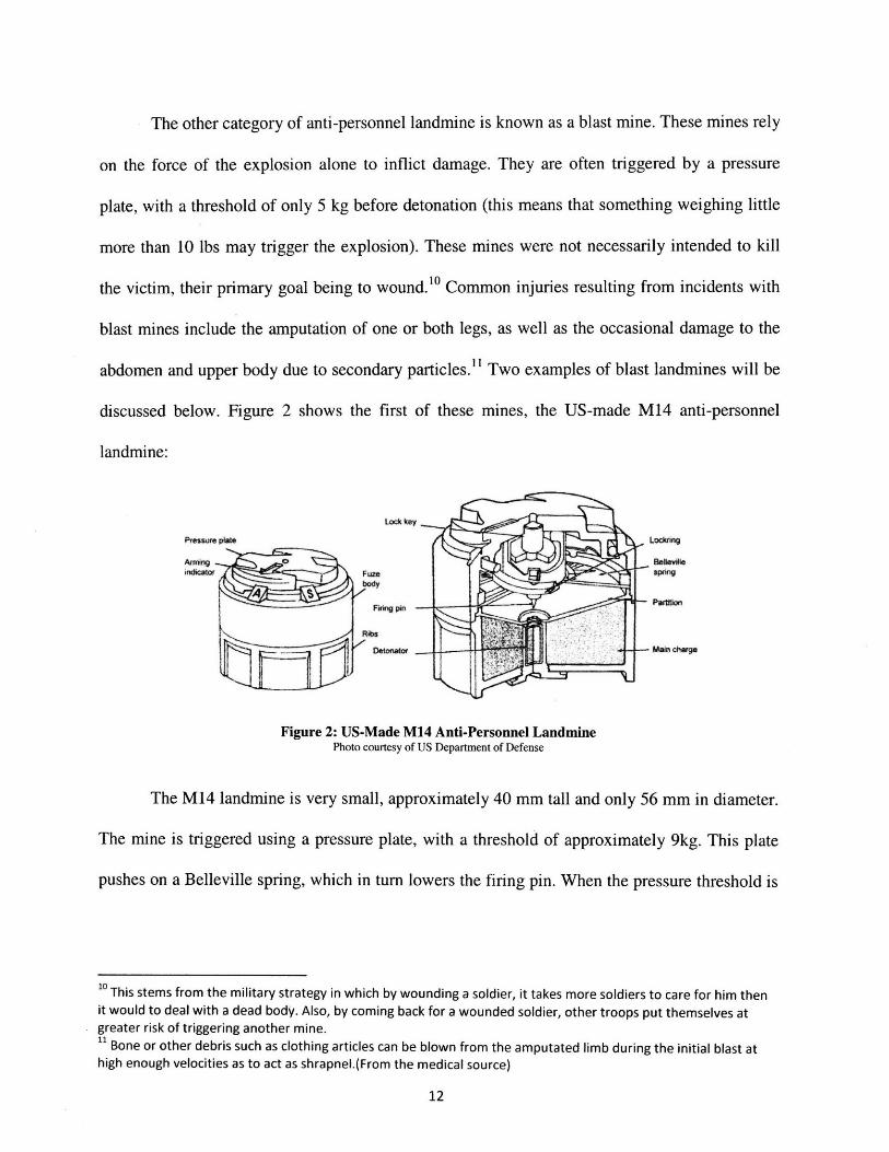
The other category of anti-personnel landmine is known as a blast mine. These mines rely
on the force of the explosion alone to inflict damage. They are often triggered by a pressure
plate, with a threshold of only 5 kg before detonation (this means that something weighing little
more than 10 lbs may trigger the explosion). These mines were not necessarily intended to kill
the victim, their primary goal being to wound.10 Common injuries resulting from incidents with
blast mines include the amputation of one or both legs, as well as the occasional damage to the
abdomen and upper body due to secondary particles."1 Two examples of blast landmines will be
discussed below. Figure 2 shows the first of these mines, the US-made M14 anti-personnel
landmine:
Pres e pkate
Aring ,rrnchcatcr
Locklng
SMain chge
Figure 2: US-Made M14 Anti-Personnel LandminePhoto courtesy of US Department of Defense
The M14 landmine is very small, approximately 40 mm tall and only 56 mm in diameter.
The mine is triggered using a pressure plate, with a threshold of approximately 9kg. This plate
pushes on a Belleville spring, which in turn lowers the firing pin. When the pressure threshold is
1o This stems from the military strategy in which by wounding a soldier, it takes more soldiers to care for him thenit would to deal with a dead body. Also, by coming back for a wounded soldier, other troops put themselves atgreater risk of triggering another mine.11 Bone or other debris such as clothing articles can be blown from the amputated limb during the initial blast athigh enough velocities as to act as shrapnel.(From the medical source)
12
crossed, the firing pin makes contact with the detonator, igniting the main charge of Tetryl
explosive (approximately 31g of explosive is used).
The M14 landmine was first introduced by the United States in the 1950's. Although this
type of mine is no longer actively deployed by the US military, many other nations around the
world have adopted the use of the M14, or of similar technology. Because of their widespread
use, these types of mines are very common in lingering minefields. Detection of these mines is
difficult, for often the firing pin is the only metal component.
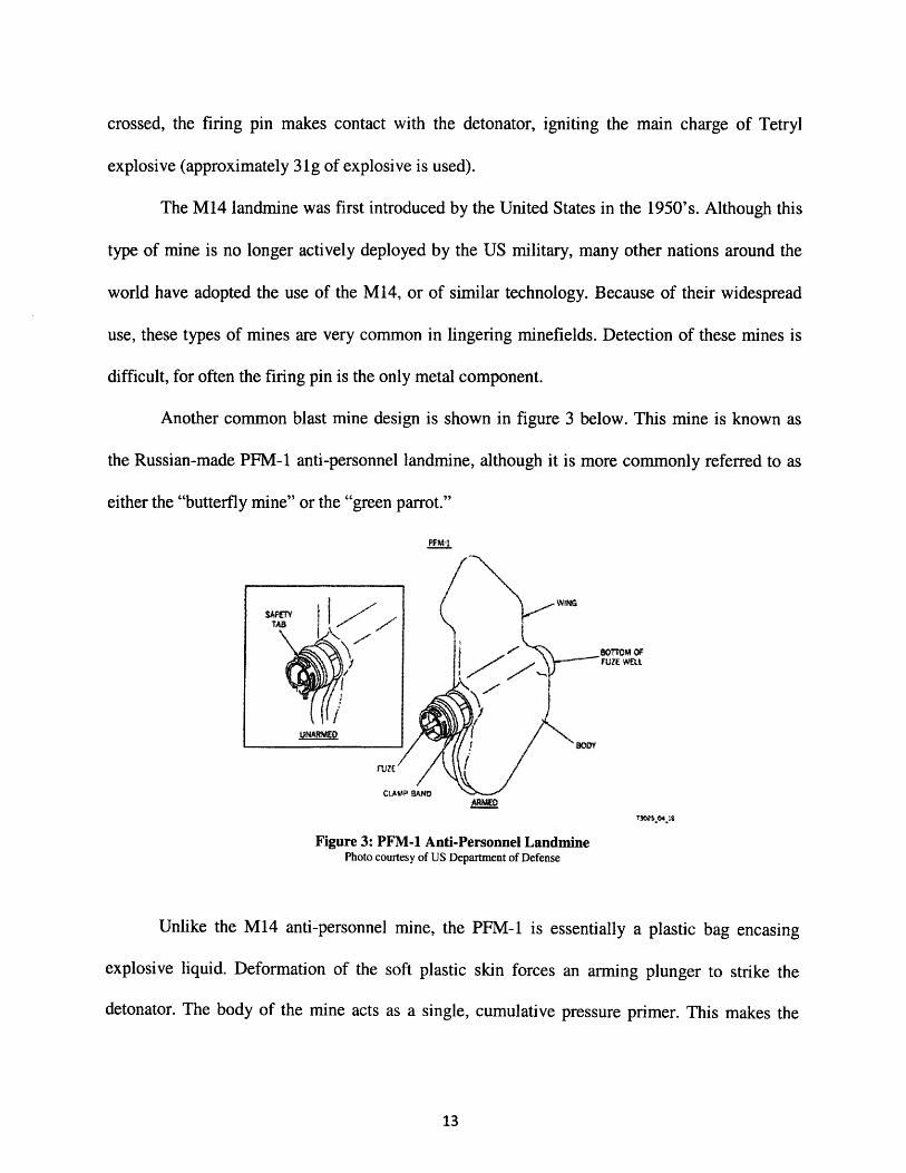
Another common blast mine design is shown in figure 3 below. This mine is known as
the Russian-made PFM-1 anti-personnel landmine, although it is more commonly referred to as
either the "butterfly mine" or the "green parrot."
PM_.
04WS 04 'S
Figure 3: PFM-1 Anti-Personnel LandminePhoto courtesy of US Department of Defense
Unlike the M14 anti-personnel mine, the PFM-1 is essentially a plastic bag encasing
explosive liquid. Deformation of the soft plastic skin forces an arming plunger to strike the
detonator. The body of the mine acts as a single, cumulative pressure primer. This makes the
iYiiTAtE

mine extremely dangerous to handle, as a single press of 5 kg or more (or alternatively multiple
presses adding up to 5kg) will bring about detonation.
The PFM-1 landmine was designed to be deployed from the air. Its unique shape is what
earned it the nickname "butterfly mine." These mines are often painted in bright colors, such as
green (hence the second nickname of "green parrot"). While the bright colors can make detection
somewhat easier, 12 they also make these landmines more attractive to children, who mistake
these deadly weapons for toys. In Afghanistan, which has the greatest concentration of PFM-1
landmines, an overwhelming number of landmine victims are children. Because these mines can
be handled before detonation, injuries sustained in landmine related incidents often involve the
amputation of one or more hands, as well as extensive damage to the upper body (Strada 1996).
Injuries to children are often fatal due to the mine's proximity to the face upon detonation.
1.2.3 Terrain
Just as there are many different types of mines to take into consideration, there are a
variety of terrains occupied by minefields. These types of terrain range from the sandy deserts
and rocky outcroppings in Northern Africa to the tropical and marsh-like locations in Southeast
Asia. Each type of terrain presents a different challenge to the demining process. For example,
dense vegetation in places such as South America can make detection and removal very difficult.
Sand filled environments pose a different challenge as mines are constantly shifted and reburied
due to the wind. Damp environments make it difficult to move heavy equipment, if the
12 Detection of the PFM-1 mine is still relatively difficult when the mine becomes buried under soil due to wind,etc. This is because, like the M14, the PFM-1 landmine contains very few metal components, making the use ofmetal detectors inefficient.
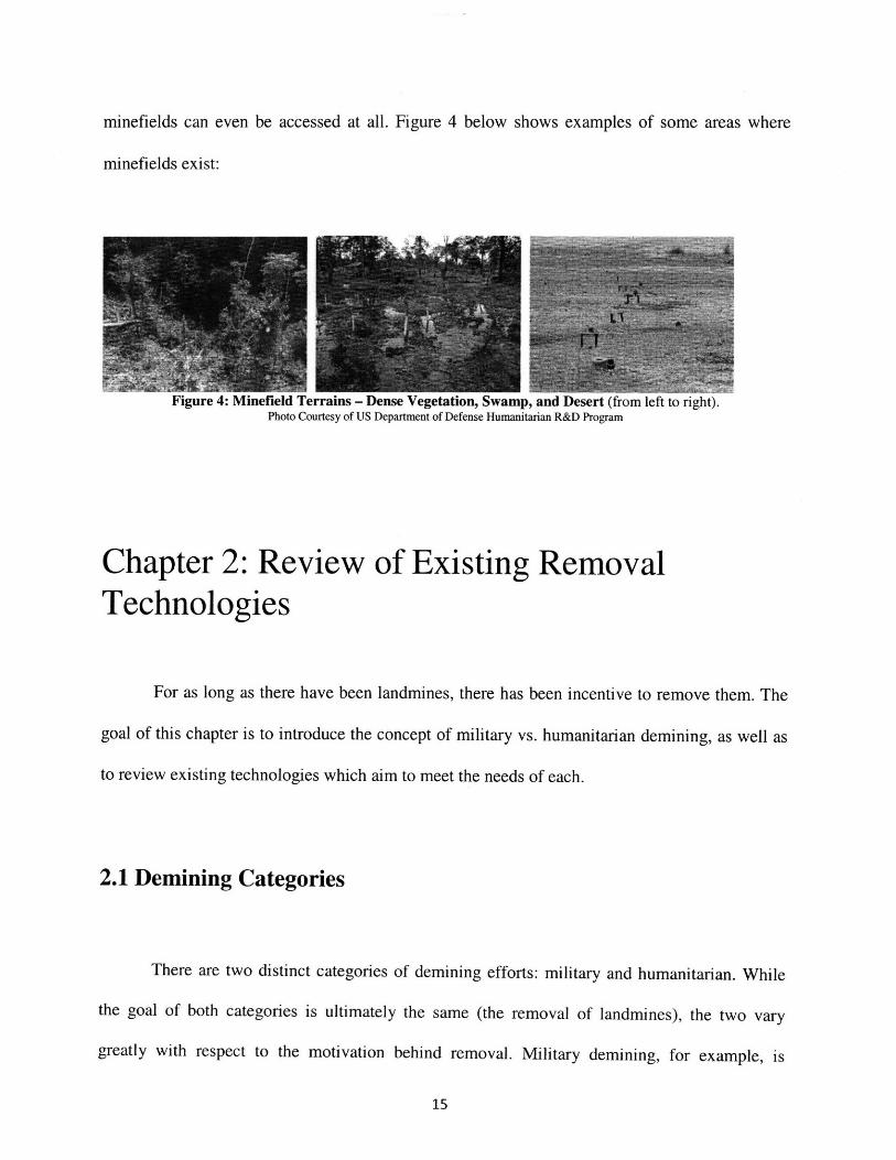
minefields can even be accessed at all. Figure 4 below shows examples of some areas where
minefields exist:
,Ir p, anu iveseri Irom lei to rigrt).Photo Courtesy of US Department of Defense Humanitarian R&D Program
Chapter 2: Review of Existing RemovalTechnologies
For as long as there have been landmines, there has been incentive to remove them. The
goal of this chapter is to introduce the concept of military vs. humanitarian demining, as well as
to review existing technologies which aim to meet the needs of each.
2.1 Demining Categories
There are two distinct categories of demining efforts: military and humanitarian. While
the goal of both categories is ultimately the same (the removal of landmines), the two vary
greatly with respect to the motivation behind removal. Military demining, for example, is
primarily motivated by the need to traverse across a minefield. The main objective is therefore to
create a safe path for vehicles, as well as for any troops which may need to pass through. Only a
portion of a field must be cleared in order to achieve the objective of creating a path. Since the
goal is to get from point A to point B, little concern is given to the fate of the remaining
minefield. Civilians may still be at risk after a military demining effort, as mines are often left in
the ground.
In contrast, the aim of humanitarian demining efforts is to remove all landmines within a
given area, thus enabling for the utilization of the formerly contaminated land. Only after an area
has met the 99.6% removal standard (as set down by the UN) can it be considered safe for
civilian occupation. Another important aspect of humanitarian demining has to do with how the
mines are dealt with. Unlike in military demining, where destruction of a mine is acceptable, in
humanitarian demining all mines must be properly removed and disposed of 13. This makes the
issue of detection that much more important. In addition, as mentioned before, much of the land
cleared through humanitarian efforts is intended for agricultural use. For this reason, important
considerations must be made in regards to the top soil conditions in these regions. The fertile top
soil must be preserved during the demining process, making methods which simply remove the
mine-containing dirt layer (such as bulldozing) unpractical for humanitarian demining.
2.2 Manual Demining
Currently the only method capable of reaching the 99.6% removal standard is manual
13 In countries where there is still political unrest or terrorist activity, it is not uncommon for civilians to removelandmines and then sell them on the black market. For this reason, in humanitarian demining mines must beremoved and accounted for before they may be destroyed.
16

demining (see figure 5 below).
Figure 5: Manual Landmine Removalhttp://www.inaroee.ebonet.net/images/homemdesminando.jpg
Manual demining is not only a time consuming task, it is also extremely labor intensive.
Trained deminers must spend hours in the field each day, often in very hot temperatures.
Deminers work within a section that is approximately 1 meter wide. Progress is slow moving, as
every forward inch must be thoroughly checked before a worker will risk stepping forward.
The biggest challenged faced by manual demining lies within the detection of mines.
Current methods include the use of a metal detector and a probe. While metal detectors are
relatively good at detecting metal encased landmines, they are not efficient at locating mines
which contain mostly plastic. Additionally, the use of metal detectors can result in a large
number of false positives. These false positives can be caused by the detection of some other
metal source, such as old bullet casings or pieces of shrapnel from a long-passed battle. As every
positive must be confirmed to ensure the safety of the worker, false readings are costly both in
time and in manual effort.
Despite the relatively low number of casualties among professional deminers, the bottom

line is that manual demining directly endangers human lives 4 . Unfortunately, until effective
alternatives can be found, it will continue to be the primary method for humanitarian demining.
2.3 Mechanical Landmine Removal Methods
As mentioned above, there is a great need for alternative methods to manual demining.
There exist today a number of such methods, a subsection of which involves the use of
mechanical equipment to detect and remove landmines. The hope is to reach an acceptable level
of clearance (99.6%) while decreasing the amount of time to do so. Within this section we will
discuss four existing methods, focusing on their attributes, limitations, and applicability to
humanitarian demining.
2.3.1 Cultivators
Cultivators are a type of landmine removal equipment which can be attached to a
bulldozer. They are designed to uncover buried anti-tank mines while maintaining the soil's
agricultural capabilities. Cultivators use a series of tines to bring the mines to the surface. In
tests, cultivator technology has been able to successfully remove mines to a depth of
approximately .2 meters (8 in). This depth can be increased up to .38 meters (15 inches) in areas
with loose soil. The uncovered mines are then passed through an auger which in turn casts them
to side allowing for easy collection and removal.
Cultivator technology has been tested on a variety of terrains, and appears to be effective
even in areas with moderate vegetation.iHowever, there are some serious limitations to consider.
14 Not only of the deminers, but also of any other civilians which may be in the area
18

For one, small anti-personnel mines may pass straight through the auger and get redistributed
into the field. There is also a chance that the mines may detonated while passing through the
auger. While the equipment is designed to be resistant to such blasts, repeated occurrence could
result in damage over time. In addition, the possibility that mines may detonate adds an extra
security risk to people who may be in the vicinity.
Another important consideration to consider is weight. Some existing prototypes which
employ the use of cultivator technology (MCC) weigh in upwards of 31 metric tons (US
Department of Defense Humanitarian Demining 1998). This makes transportation of the device
difficult. The immense weight also means that the cultivator will not be useful in areas with
damp terrain, for it will tend to sink into softer ground. This technology is therefore inapplicable
to many affected regions, such as those in the wetlands of Southeast Asia.
Despite its limitations, cultivator technology does appear to be a step in the right
direction. The effective removal of anti-tank mines is encouraging, although improvements to the
technology will need to be made before this can be used as a humanitarian demining tool, the key
concern being the capability to remove of anti-personnel mines.
2.3.2 Mine Blades
A mine blade is an array of digging teeth designed to take the place of a standard
bulldozer blade. The digging teeth are passed through the soil, pulling up a mixture of dirt and
larger objects such as landmines. The collected material is then passed through a series of sifting
teeth; the larger objects are sorted out whilst the dirt is returned to the field. As with a cultivator,
the sorted landmines are deposited to the side of the bulldozer for later removal.
A unique feature of a mine blade is the ability to preset the depth at which the digging
teeth will rake the field. This control allows for a constant clearing depth, ensuring for the most
19
efficient removal of any landmines.
Unlike other removal methods such as military plows or the use of standard bulldozer blades,
mine blades do not require highly trained operators. The use of a mine blade also eliminates the
constant adjustments that are required to ensure that conventional removal methods are effective.
Just as a small landmine may pass through the auger of a cultivator, so might one pass
through the sifter mechanism in a mine blade. This can result in the return of smaller mines to
the path being cleared. Technological advances will need to be made in order to prevent this
redistribution of mines before the mine blade can be used as a humanitarian demining tool.
Another issue which must also be addressed is the high probability that anti-personnel mines
may detonate upon passing through the sifting teeth. While the mine blade is designed to be
resistant to mine blasts, repeated explosions could result in damage to the unit. Explosions also
pose a risk to nearby persons; in addition to making it unsafe to operate the unit manually (thus
remote controlled vehicles become a necessity).
2.3.3 Flails
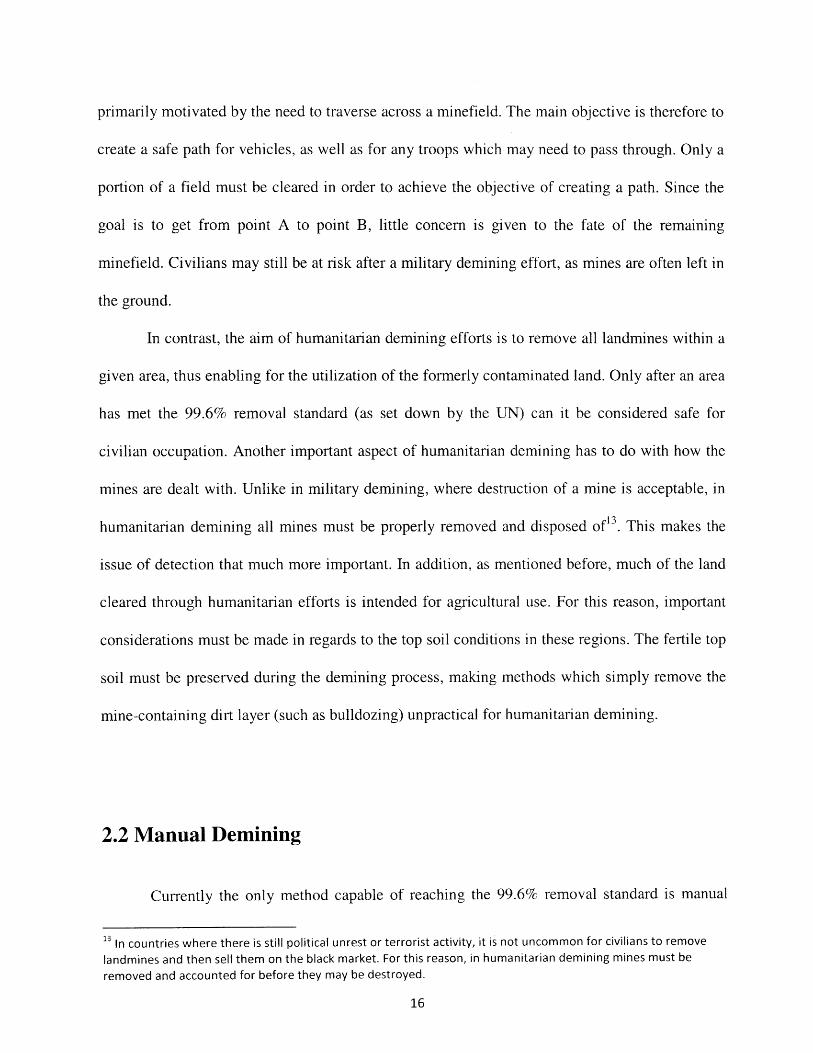
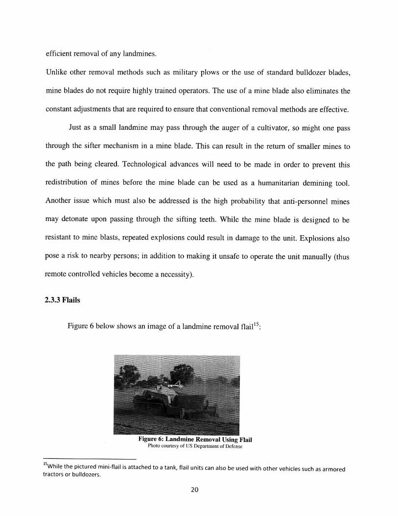
Figure 6 below shows an image of a landmine removal flail 15 :
r i ux v u u. •aummIle inumovai using r ailPhoto courtesy of US Department of Defense
1sWhile the pictured mini-flail is attached to a tank, flail units can also be used with other vehicles such as armoredtractors or bulldozers.
Different from previously discussed technologies, the function of a flail is not to remove
landmines, but rather to destroy them in the field. Heavy chains attached to a spinning rotor are
used to beat the ground. The force of impact is creates enough ground pressure to trigger most
anti-personnel mines. Because a flail causes the detonation of the landmine, it is necessary to use
a heavily armored, remote controlled vehicle.
While flails are effective against most anti-personnel landmines, 16 they cannot be used in
regions where the presence of anti-tank mines is suspected (the damage inflicted by an anti-tank
mine is enough to render a flail unit, along with the coupled vehicle, inoperable). In many
instances, a minefield must first be checked manually to ensure the safety of the flail. This
dependence on manual checks greatly undercuts the flail's ability to be used as a primary
demining tool. Additionally, the motion of the chains may actually fling some landmines into
previously cleared regions, thus requiring additional manual checks. For this reason, the use of
flails appears to be more applicable to military use, where a single path is all that is needed.
However, due to the limitations of the technology, it is clear that there may be better alternatives
when it comes to demining in general.
2.3.4 Earth Tillers
Similar to flails, earth tillers aim to destroy mines rather than remove them. These
machines are designed to crush both anti-tank and anti-personnel mines. For this reason, earth
16 Some mines, such as blast-hardened mines and mines with small pressure plates, may fail to detonate evenwhen passed over by a flail demining unit.
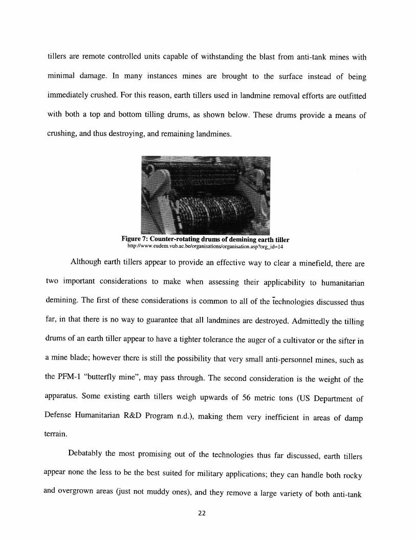
tillers are remote controlled units capable of withstanding the blast from anti-tank mines with
minimal damage. In many instances mines are brought to the surface instead of being
immediately crushed. For this reason, earth tillers used in landmine removal efforts are outfitted
with both a top and bottom tilling drums, as shown below. These drums provide a means of
crushing, and thus destroying, and remaining landmines.
Figure 7: Counter-rotating drums of demining earth tillerhttp://www.eudem.vub.ac.be/organisations/organisation.asp?org_id=14
Although earth tillers appear to provide an effective way to clear a minefield, there are
two important considerations to make when assessing their applicability to humanitarian
demining. The first of these considerations is common to all of the technologies discussed thus
far, in that there is no way to guarantee that all landmines are destroyed. Admittedly the tilling
drums of an earth tiller appear to have a tighter tolerance the auger of a cultivator or the sifter in
a mine blade; however there is still the possibility that very small anti-personnel mines, such as
the PFM-1 "butterfly mine", may pass through. The second consideration is the weight of the
apparatus. Some existing earth tillers weigh upwards of 56 metric tons (US Department of
Defense Humanitarian R&D Program n.d.), making them very inefficient in areas of damp
terrain.
Debatably the most promising out of the technologies thus far discussed, earth tillers
appear none the less to be the best suited for military applications; they can handle both rocky
and overgrown areas (just not muddy ones), and they remove a large variety of both anti-tank
22
"`

and anti-personnel landmines. However, earth tillers still destroy the mines, which is not in
accordance with humanitarian demining protocols.
2.4 Alternative Methods for Landmine Removal
Current research is being done to develop non-mechanical demining technologies. Many
of these alternative methods are aimed at detection rather than removal. Right now, the goal is to
reduce the risk to manual deminers by determining the location of landmines remotely before
any physical demining is undertaken. However, the implication for alternative detection
technologies goes much farther. If proven to be reliable methods of detection, these technologies
could potentially be used in conjunction with robotic removal equipment, thus removing the need
for manual deminers all together.
2.4.1 Electromagnetic Detection Methods
Electromagnetic detection methods utilize the observable differences between the
electromagnetic properties of both soil and landmines. They involve the use of electromagnetic
waves, introduced into the soil, as a tool for distinguishing landmines from the surrounding
ground. In this section, we will discuss three such methods for currently being explored: ground
penetrating radar, electrical impedance tomography, and infrared/hyperspectral systems.
Ground Penetrating Radar
Ground penetrating radar (or GPR as it will henceforth be referred to) is a well-developed
technology. However, its use in the application of humanitarian demining is rather new. GPR
takes advantage of the fact that different materials have different dielectric constants. During the
23

detection process, radio waves are emitted into the ground. Wave reflection patterns are then
observed (MacDonald, et al. 2003). It is important to note that neither the emission nor the
observation processed require contact with the soil. Therefore, the technology may be employed
from a distance to ensure the safety of the demining crew. Reflections often happen at locations
where there are discontinuities in the dielectric constant, for example the boundary between a
landmine and the surrounding soil.
One of the greatest advantages of this technology is that it can be used to detect mines
with all types of casings, both metal and plastic (this is due to the fact that both metal and plastic
have different dielectric constants than that for soil). However, despite this promising aspect of
GPR, there are some limitations. To begin with, the technology can be greatly impacted by soil
conditions; the presence of roots or large rocks may lead to false positives. In addition, a high
quality image is often necessary to accurately distinguish landmines from other noise which may
be observed. This image quality may be increased by increasing the wavelength at which the
radio waves are emitted. However, the amount of ground penetration decreases as the
wavelength increases, thus GPR is only effective when locating surface mines. Therefore,
although GPR appears to be a fairly promising technology, further development is needed before
it can be applied to humanitarian applications, which require the removal of buried mines as
well.
Electric Impedance Tomography
Electrical Impedance Tomography involves the introduction of an electric current to the
soil in order to observe the conductivity profile. As with ground penetrating radar, electric
impedance tomography allows for the detection of many different mines, including both those
with metal and plastic casings. Unlike GPR however, this electric method involves the placement
24
of electrodes into the ground, thus requiring human involvement in the field. This involvement
means that there is still a chance for worker injury or death.
Another limitation to electric impedance technology is that its effectiveness is highly
dependent upon terrain conditions. For example, dry non-conductive soils (such as that which
may be found in a desert minefield) render the technology useless. That being said, there may be
some very useful applications of the technology with respect to wet terrain. As we have
discussed before, wet terrain (such as that found in tropical settings) makes the use of mechanical
equipment difficult due to the weight of the machines. Electric impedance technology does not
have this issue with weight. Additionally, the water in the environment helps to conduct the
electricity introduced, helping, rather than hindering, the detection process.
Infrared/Hyper- spectral Detection
Infrared/hyper-spectral detection technology uses the observation that landmines (or the
soil/vegetation directly above them) tend to either reflect or emit radiation differently than the
surrounding soil. These technologies encompass a variety of methods using both active and
passive irradiation over a broad range of electromagnetic wavelengths (MacDonald, et al. 2003).
Most of these methods fit into two categories: thermal or non-thermal.
Thermal detection methods aim to expand on the observation that the soil/vegetation
above a landmine appears to be warmer in temperature during the day, while also having a faster
rate of cooling at night (MacDonald, et al. 2003). Laser illumination or high powered microwave
radiation can help to induce these observable temperature profiles.
Similar to the difference in temperature associated with a mine is the observation that
light (natural or artificial) is reflected differently by the areas surrounding a landmine. Not only
do the different materials found in landmines reflect light differently, but the actual process of
25

laying mines may allow for later detection (the act of burying a landmine can cause the natural
particle distribution in the soil to be disrupted, therefore changing the way which the soil scatters
light).
Although the use of infrared/hyperspectral technology appears to be an attractive solution
to landmine detection (there is no physical contact with the field, can be deployed from aircraft,
etc), there are severe limitations which make it unfeasible for practical use. The primary
limitation is that the technology is highly sensitive to changes in the environment. The resultant
variation in performance levels makes it hard to consider the technology a reliable method in
landmine detection. With respect to thermal methods, the wavelength of radiation needed to
produce the desired effects corresponds to poor soil penetration. Therefore, many of these
methods rely on the observation on naturally occurring thermal radiation. However, the
anomalies associated with landmines are easily erased by such things as weathering, thus making
the detection of buried mines possible only under limited transient conditions 7
2.4.2 Acoustic/Seismic Detection Methods
Whereas the technologies thus far discussed have all exploited the electromagnetic
properties of materials, acoustic/seismic technology takes advantage of the mechanical properties
of both the landmine and the surrounding soil. In this case, the exploited property relates to the
fact that different materials vibrate differently when exposed to sound waves. Acoustic/seismic
mine detection typically involves sound generated from a loudspeaker. While some of the
acoustic energy is reflected by the ground surface, a portion of it penetrates the ground in the
17 It is important to note that while the technology is currently not suitable for humanitarian demining on account
of the inability to detect buried mines, it has proven to be fairly successful at the detection of surface mines,especially when employed by aircraft.
form of waves which then propagate through the soil. When a wave comes into contact with an
object such as a mine, some of the energy is reflected upwards, causing vibrations at the surface
level. Sensors can then be used to detect these vibrations without making contact with the
ground. 18
Thus far, acoustic sensing appears to be fairly reliable in that it does not yield many false
positives 19 (MacDonald, et al. 2003). The technology also appears to be effective independent of
weather and terrain conditions, although some studies indicate that frozen ground may affect
sensing capabilities. Mine depth is another aspect capable of having an effect on acoustic/seismic
sensing. This is due to the fact that the resonant response (the surface vibrations caused by the
reflected acoustic waves) greatly decreases with the depth at which the mine is buried. Therefore,
like many of the other alternative technologies discussed thus far, acoustic/seismic sensing is as
of yet only applicable to the detection of surface mines. The technology will need to improve if
this method is going to be used in humanitarian demining applications.
2.4.3 Chemical methods
Chemical methods are different in that the goal is not to detect the metal or plastic of a
landmine's casing, but rather to detect the explosives within. There are two main approaches to
chemical sensing: detection of chemical vapors within the air, or detection within the soil. In the
latter method, it is sometimes necessary to obtain a soil sample before testing can take place. As
this would involve manual collection, this method of chemical testing is not very applicable to
18 Some tested sensors include laser Doppler vibrometers, radars, ultrasonic devices, and microphones.(MacDonald, et al. 2003)19 Acoustic/Seismic sensing seems to eliminate many of the false positives associated with rocks and scrap metal;although hollow objects such as soda bottles and cans can give false readings due to the fact that the resonancepatterns of these objects are similar to those of landmines. (MacDonald, et al. 2003)
27

humanitarian demining, at least not as a primary detection method20. The other form of chemical
testing, however, appears more promising. Through the use of specialized polymerS21, it is
possible to detect trace amounts of chemical vapor in the air (as little as 10-15 g explosive
material per ml air). This vapor is a product of leaked explosives.
The limitations of chemical detection include the fact that chemical weapons cannot as of
yet be deployed on a large scale. Current technology is better suited to work with a manual
deminer, with the chemical methods taking place of the traditional metal detector. However, with
some advancement of technology, it is not unreasonable to assume that chemical methods, more
specifically ones which detect explosive vapors, could be used with robotic removal equipment.
Again, the chemical sensors would take the place of more traditional methods of detection.
However, before chemical methods can be employed by either manual or robotic
deminers, they need to have a probability of almost 1 relating to mine detection. Because factors
such as the environmental conditions or the presence of other explosive remnants greatly affect
the effectiveness of chemical methods, it is unlikely that chemical tools will replace existing
removal technology (such as the simple demining prod) anytime soon.
2.4.4 Biological Methods
Fluorescing Organisms
Just as there are chemical methods designed to detect the presence of explosive vapor in
the air (or trace elements of explosives in the soil), so are there biological ones. One subsection
20 There may be a use for this type of chemical testing as a confirmatory method once suspected landmines aremarked.21 Different types of polymers include for example ones which lose fluorescent capabilities upon the adhesion ofexplosive molecules, as well as polymers which absorb explosive molecules, thus changing their overall mass in anobservable way.

of biological methods involves the use of organisms which fluoresce in the presence of
explosives. These organisms are often genetically engineered by inserting a regulatory protein
which, upon the recognition of an explosives molecule, will initiate fluorescence (MacDonald, et
al. 2003).
This method has been tested in both plants and bacteria. While detection is possible with
both organisms, each presents its own problems. For one, plants are not easily distributed
throughout a minefield; a person cannot be expected to go into a field to plant the plants, and it
takes too long for results to make the distribution of seeds desirable. Bacteria on the other hand
are easily distributed. However, the effectiveness of distribution is dependent on soil conditions
(dry soil will absorb the bacteria making it impossible to detect them even if they are
fluorescing), as well as environmental conditions. In addition, there are strong protests to
spraying genetically engineered bacteria over a region which may later be used for agricultural
purposes.
Detection Using Trained Animals
Perhaps the most promising and advanced alternative detection technology involves the
use of explosion sniffing dogs. The use of dogs has long been employed in mine affected areas
due to their ability to locate mines using their heightened sense of smell (dogs are capable of
detecting explosive vapors at lower concentrations than any available chemical sensors). By
offering a small reward, such as food or play, it is possible to train dogs to signal when they
smell a mine (this is usually done by having them sit upon first detection). A manual deminer
then follows and investigates the suspect area.

Figure 8: Canine Deminingwww.roncoconsulting.com
While demining dogs are effective, the greatest drawback to using them is the cost; one
dog can cost more than 10,000 USD to train (RONCO Consulting Corporation 2008). This high
cost (especially for an animal which is at mortal risk each day) is often too high for poorer
communities to pay. And even in areas which can afford the animals, results are not one hundred
percent guaranteed, as performance is greatly dependent upon the dog and/or trainer. Regardless
of these shortcomings however, it is certain that dogs will continue to remain a valuable tool in
humanitarian demining.
Chapter 3: Design for Demining
In the previous chapters, we have attempted to explain the issue of landmine removal
(with an emphasis on humanitarian demining), as well as describe various existing removal
technologies. In the remainder of this work, we will present and discuss a new design related to
humanitarian demining. Our goal is to create a robotic unit which could be used in place of
manual demining. As discussed above, one of the most effective detection methods involves the
use of landmine-sniffing animals, predominately dogs. We aim to utilize the natural adeptness
observed in these animals by designing a robot which can work in conjunction with them.
Important to note is that this design is still in the concept phase, anything beyond is not
within the scope of this paper. However, this work could be used to develop further prototypes
which could lead to potential testing of the design within the near future.
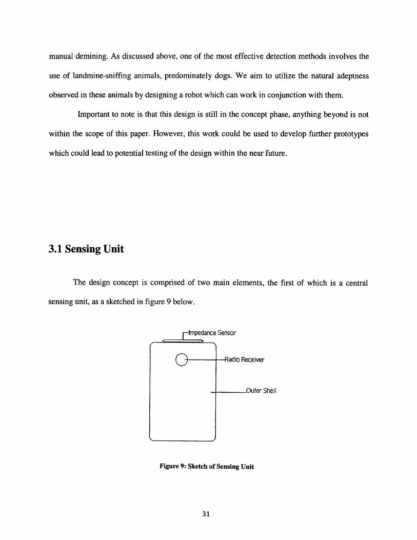
3.1 Sensing Unit
The design concept is comprised of two main elements, the first of which is a central
sensing unit, as a sketched in figure 9 below.
Impedance Sensor
-Radi o Receiver
Outer Shell
Figure 9: Sketch of Sensing Unit
3.1.1 Outer Shell
The sensing element is essentially a group of sensors encased in a solid outer shell, which
can be made of either metal or hard plastic2 2. The important design constraint for the outer shell
(which also pertains to the rest of the robot) is weight; the shell must be large enough to hold the
necessary sensors, and yet the entire unit must weigh less than 5 kg (approximately 11 Ilbs) so as
to avoid triggering any of the landmines during the detection process 23. Along with being
lightweight, the outer shell must also be waterproof, as well as weather proof, so as to protect the
sensing equipment from the elements.
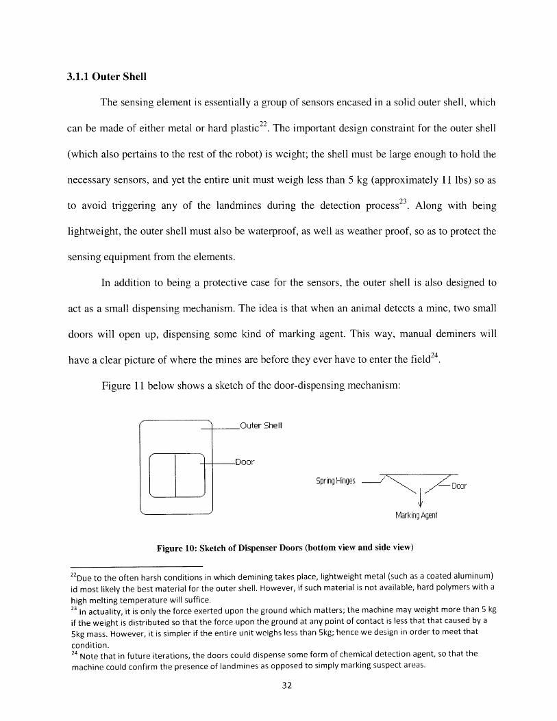
In addition to being a protective case for the sensors, the outer shell is also designed to
act as a small dispensing mechanism. The idea is that when an animal detects a mine, two small
doors will open up, dispensing some kind of marking agent. This way, manual deminers will
have a clear picture of where the mines are before they ever have to enter the field 24
Figure 11 below shows a sketch of the door-dispensing mechanism:
Shell
Spring Hinges -/ - Door
+nrn nnIMldl linly H IYe
Figure 10: Sketch of Dispenser Doors (bottom view and side view)
22Due to the often harsh conditions in which demining takes place, lightweight metal (such as a coated aluminum)
id most likely the best material for the outer shell. However, if such material is not available, hard polymers with a
high melting temperature will suffice.23 In actuality, it is only the force exerted upon the ground which matters; the machine may weight more than 5 kgif the weight is distributed so that the force upon the ground at any point of contact is less that that caused by a5kg mass. However, it is simpler if the entire unit weighs less than 5kg; hence we design in order to meet that
condition.24 Note that in future iterations, the doors could dispense some form of chemical detection agent, so that the
machine could confirm the presence of landmines as opposed to simply marking suspect areas.
32
In order to save space, the doors must operate in as simple a fashion as possible. That is
why we propose the use of two spring-loaded doors. Upon detection of a mine, these doors
would open, allowing for the dispersion of the marking agent. The spring action of the doors will
return them to the closed position. As for opening the doors, something as simple as a solenoid
could be used to apply pressure to the doors, forcing them open, and thus enabling dispersion.
Note this design can be modified in future iterations to incorporate the use of alternative
detection methods (such as the chemical methods discussed earlier in chaper2) in addition to the
use of marking agents.
Lastly, a subtle yet important design aspect of the outer shell is that it is to have no sharp
corners. This is to ensure that the unit does not become tangled in any existing vegetation, and
also to ensure the safety of both the human and animal workers involved; we do not want any
sharp corners available to cut hands, legs, paws, etc, especially if the outer shell is made of
metal.
3.1.2 Sensors
As previously mentioned, a number of sensors will be used. While the eventual goal aims
to incorporate detection sensors, the first iterations the majority of sensors will be used for
navigation purposes, which will enable the robot to traverse a minefield without running into
objects or getting stuck.
During the first stages of development, the unit will be comprised of three primary
sensors: a radio receiver, an impedance sensor, and a proximity sensor. The proximity sensor

will be used to determine how close the robot is from objects, rocks and trees for example. This
way the robot will know when it is approaching an object so that it can react accordingly.
The main purpose of the impedance sensor is to enable the robot to identify objects as
either hard (cannot pass through) or soft (can proceed on course). It is comprised of a spring and
a displacement sensor attached to the front of the machine. When the robot makes contact with
an object, the spring will compress. The amount of compression is related to the stiffness of the
object in the path (the more compression, the harder the object). If the spring compresses beyond
a certain threshold, then the robot will know that it cannot push through whatever object is in its
path. It will subsequently find an alternative route 25.
The last main component is the radio receiver. The idea is to have this receiver interact
with a radio transmitter located on the collar of the working animal. The robot could then track
the motion of the animal during the demining process. When the animal stops (as demining
animals are trained to do upon detection of a mine), the robot would be able to detect the lack of
motion. It would then movie to the signal, and dispense the marking substance near the animal.
This would allow the animal and robot to mark the entire field without any human interaction.
Once the minefield is marked, manual deminers will be able to go directly to the marked areas
and remove the landmines 26
As the technology progresses, so will the function of the robot. Initially a marking tool,
by the final iteration, the intention is for the robot to be able to detect landmines entirely on its
25 It is important to note that we have been referring to the robot "knowing", etc. This is because the robot will be
made to be completely autonomous. The benefit of this is that no special training will be required to operate the
unit, making it more accessible across the globe.26 Admittedly, there are many possible issues with this method of demining. For one, the animals usually work on a
leash. Taking them off of the leash, it could not be guaranteed that they would clear in the straight path so
distinctive to manual demining. In addition, animals may develop bad habits if they discover that simply bystopping they are rewarded as treat (the robot will be designed to dispense some small reward). Modifications in
dog training may help to alleviate these problems.

own. This will not be possible however, until alternative methods for detecting landmines are
improved so as to provide the same level of performance attained using trained animals.
3.2 Locomotion
The remainder of this work has to do with the design for locomotion. After all, the
sensing unit will be of little use if the robot cannot traverse a minefield. We will look at two
methods of locomotion, and discuss why one may be more efficient than the other for the
application of humanitarian demining.
3.2.1 Locomotion Methods
There are two main methods available for the application of robot locomotion; the use of
wheels or the use of mechanical legs. While wheels present a well developed, straightforward
method for locomotion (after all, the wheel has been around for hundreds of years), we argue that
it is not the best method for our purpose of humanitarian demining. Instead, we will look at the
use of mechanical legs as a means of moving the robot.
3.2.2 The Benefit of Mechanical Legs
The most apparent benefit of using mechanical legs instead of wheels lies in the ability to
traverse multiple types of terrain, especially areas of soft ground. Whereas the motion of a wheel

will actually hinder its own motion over soft terrain (as shown in figure *** below), by using
legs, we can take advantage of the spring-like properties of the ground. As the leg impacts the
ground, some of the energy is stored in the deformed soil. As the soil "springs back", an upward
force is exerted upon the leg, helping to propel it forward. This is much like what happens when
a runner's foot impacts the ground.
The following calculation was done to further explore this concept:
We can model the legs as a wheel with rigid spokes. By looking at the equation of motion
for the system, as well as the collision dynamics, it is possible to come up with a system of
equations which can then be used to simulate the interaction between the legs and a soft terrain.
Equation of Motion
We can use the Lagrange method to find the equation of motion for the system shown in
figure 11 below:
Figure 11: Leg Modeled as Mass-Rod Pendulum
Where M is the mass of the wheel, g is the acceleration due to gravity (approximately 9.8m/s2), a
is angle between the surface and the horizontal plain, 0 is the angle of the rod with respect to the
horizontal plane, and 1 is the length of the spoke. Note x and y represent the x and y components
of 1. Also note that for simplification, we are treating it as a fixed mass and a single rod, acting as
a pendulum on some incline a.
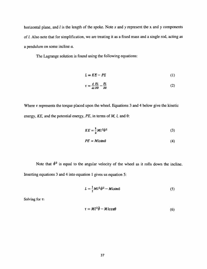
The Lagrange solution is found using the following equations:
L = KE -. PE (1)
da aL (2)T - (2)
Where r represents the torque placed upon the wheel. Equations 3 and 4 below give the kinetic
energy, KE, and the potential energy, PE, in terms of M, 1, and 0:
KE = Ml22O (3)
PE = MlsinO (4)
Note that 62 is equal to the angular velocity of the wheel as it rolls down the incline.
Inserting equations 3 and 4 into equation 1 gives us equation 5:
L = M12zgz - Mlsim6 (5)
Solving for T:
T M= 2 - M IlcosO (6)
The torque applied to the wheel is a function of both the angular position, 9 and the
angular acceleration, 6. If we rewrite equation 6 in matrix form, it is possible to solve for both
the angular position and angular acceleration, allowing us to model the motion of the system as a
whole.
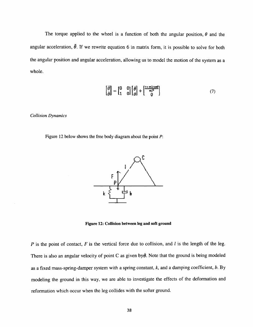
Collision Dynamics
Figure 12 below shows the free body diagram about the point P:
Figure 12: Collision between leg and soft ground
P is the point of contact, F is the vertical force due to collision, and 1 is the length of the leg.
There is also an angular velocity of point C as given bye. Note that the ground is being modeled
as a fixed mass-spring-damper system with a spring constant, k, and a damping coefficient, b. By
modeling the ground in this way, we are able to investigate the effects of the deformation and
reformation which occur when the leg collides with the softer ground.
to0 +rT+ mZcs1 01

Basic collision dynamics states that the post-collision velocity,~9P , is equal to the pre-
collision velocity, 4' , multiplied by the negative coefficient of elastic collision, e, as shown in
equation 8 below:
•9post = -ej99P"f9 - P (8)
We know that the value of e is dependent upon the values of both k and b. The
relationship between the three can be determined experimentally, however for our purpose we
will simply model the relationship as in equation 9 below.
(kb)/a(kb)/a + 1 (9)
Equation 9 above is a suitable model, for as kb goes to zero, so does the coefficient of
elastic collision (which would mean a perfectly inelastic collision), whereas if kb goes to infinity,
so does e (which would be a perfectly elastic equation).
Three more important equations are given below:
6P _ IIF=r i Xrq,-ilF ii'1 - rM
t (10)
•p,,s• =o•- IIFII-c M! (11)
9po=t = 0It + o x r (12)P +(12)
Equations 10, 11, and 12 above give us the post-collision conditions. Solving for the post
collision velocity give equation 13:
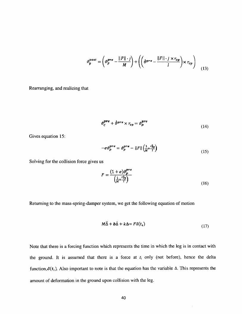
(13)
Rearranging, and realizing that
01 'V + b6re x r -= r (14)C ap (14)Gives equation 15:
_ 8e = ,Pre - IIFII1 +rp-P I ) (15)
Solving for the collision force gives us
F =(,j Tfp
(16)
Returning to the mass-spring-damper system, we get the following equation of motion
MA + bA + kA= Fd(t1) (17)
Note that there is a forcing function which represents the time in which the leg is in contact with
the ground. It is assumed that there is a force at ti only (not before), hence the delta
function,6(t]). Also important to note is that the equation has the variable A. This represents the
amount of deformation in the ground upon collision with the leg.

Rewriting equation 17 in matrix form, we get
[Ab ] r1(18)
Lastly, if we combine the matrix equations for both the equation of motion and the collision
forces components, we can get a system of ordinary differential equations which can be used to
model the behavior of a leg upon collision with soft ground.
10 0 0A 000[AJ101 OLA
3.2.3 Further Applications
Using some numerical program such as MATlab, it is possible to use equation 19 to
simulate the motion of a leg upon collision with the ground. We would expect the results of such
a simulation to show an additional force when the leg leaves contact with the ground (after the
initial collision, the leg remains in contact with the ground for a small amount of time, then lifts
up again). This force is caused by the restoration of the soil back to its original position (after the
deformation caused by the initial collision). We would expect this force to add to the forward
motion of the leg, and in turn the robot. However, just as the sensing design is in the preliminary
stages, so is this simulation. Further testing will be needed in order to determine the extent of
energy gained due to the spring back of the ground.
/rrr\Si Ii~
Bibliography
Adopt-a-Minefield. Landmine: A History. http://www.landmines.org/crsis/history.cfm (accessed 5 2008).
Bonsor, Kevin. How Landmines Work. June 19, 2001. http://science.howstuffworks.com/landmine.htm(accessed 4 20, 2008).
Human Rights Watch. Landmine Monitor Report. United States: International Campaign to BanLandmines, 2006.
International Committee of the Red Cross. Anti-personnel Landmines Friend or Foe? Geneva:International Committee of Red Cross, 1996.
Landmine Monitor Group. Landmine Monitor Report. United States: International Campaign to BanLandmines, 2006.
-. Landmine Monitor Report. United States: Interntional Campagn to Ban Landmines, 2007.
Landmine Survivors Network. Landmine Survivors Network. www.landmine-survivors.org (accessed 420, 2008).
MacDonald, Jaqueline, et al. Alternatives for Landmine Removal. Santa Monica: RAND, 2003.
RONCO Consulting Corporation. Mine/UXO Clearance FAQ Demining with Dogs. 2008.http://www.demining.com/hmc/faq.html (accessed 5 1, 2008).
Strada, Gino. "The Horror of Landmines." Scientific American, 1996.
US Department of Defense Humanitarian Demining. "Developmental Technologies." 1998.
US Department of Defense Humanitarian R&D Program. Minefield Challenges. www.humanitarian-
demining.org/NewDesign/Threats_minefield.asp (accessed 4 27, 2008).