Laminar Jamming Flexure Joints for the Development of ...
7
Laminar Jamming Flexure Joints for the Development of Variable Stiffness Robot Grippers and Hands Lucas Gerez, Geng Gao, and Minas Liarokapis Abstract— Although soft robots are a good alternative to rigid, traditional robots due to their intrinsic compliance and environmental adaptability, there are several drawbacks that limit their impact, such as low force exertion capability and low resistance to deformation. For this reason, soft structures of variable stiffness have become a popular solution in the field to combine the benefits of both soft and rigid designs. In this paper, we develop laminar jamming flexure joints that facilitate the development of adaptive robot grippers with variable stiffness. Initially, we propose a mathematical model of the laminar jamming structures. Then, the model is experimentally validated through bending tests using different materials, pressures, and number of layers. Finally, the soft, laminar jamming structured are employed to develop variable stiffness flexure joints for two different adaptive robot grippers. Bending profile analysis and grasping tests have demonstrated the benefits of the proposed jamming structures and the capabilities of the designed grippers. I. I NTRODUCTION Over the last decade, the soft robotics field has received an increased interest from the research community. Robots have evolved from rigid mechanisms to soft, flexible, and customized systems [1]. The success and popularity of soft robots are due to the intrinsic mechanical properties (e.g., compliance) of soft materials that provide high environ- mental adaptability, conforming to complex shapes, and withstanding significant crushing loads. For this reason, the materials applied in soft robots play an important role in the behaviour and the capabilities of this class of robots. Although soft materials can assist robots in adapting to the object’s geometry and grasp fragile items, they suffer from several drawbacks, such as low control accuracy, low force exertion capability, and low resistance to deformation [2]. In order to overcome these disadvantages, researchers have developed methods to selectively control the stiffness of soft structures. Depending on the selected material and working principle of the variable stiffness module, stiffness can be controlled by varying the temperature, electrical current, pressure, and magnetic field of the device. Such structures can be used in devices applied in the medical industry, structural engineering, automotive, and aerospace industries [3]. In [4], the authors propose a shape memory alloy-based soft gripper, which can control the stiffness of the joints, increasing the grasping force ten times. The limitation of shape memory alloy (SMA) and shape memory polymer (SMP) structures is their low response speed due Lucas Gerez, Geng Gao, and Minas Liarokapis are with the New Dexterity research group, Department of Mechanical Engineering, The University of Auckland, New Zealand. E-mails: [email protected], [email protected], [email protected] Fig. 1. Two adaptive robot grippers have been developed using laminar jamming flexure joints. The jamming structure allows for control of the stiffness of each joint. The top subfigure presents the two-fingered gripper, while the bottom subfigure presents the three-fingered gripper. to the high amount of time required to change the material temperature and, therefore, its stiffness [5], [6]. In [7], the authors present a robot gripper that utilizes the effects of a magnetorheological (MR) fluid (viscosity changes according to the magnetic field applied) to conform the fingerpad of the gripper to the object’s shape. The limitation of MR fluids is that they require heavy electromagnets to generate sufficient magnetic flux density for the solidification of the MR fluid [8]. Additionally, the use of a magnetic field can limit interactions with magnetically sensitive materials / objects, potentially damaging them in the process. In [9], the authors propose voltage-actuated dielectric elastomer beams that can be used to grasp several objects. However, the deformation and change in stiffness achieved by the dielectric elastomer actuators (DEA) are not enough to withstand more than a few grams of weight [10], [11]. Another method for tuning stiffness of soft structures is by applying a pressure gradient into a closed system (e.g., pouch) and relying on the contact between solid parts to alter the stiffness of the soft structure. In [12], the authors propose a joint assistance device based on the jamming of granular parts. Rubber granules are filled into a silicone sleeve, and the pressure change inside the sections varies the stiffness of the device. In [13], the authors combine a granular jamming structure with pneumatic soft actuators to increase the efficiency of a soft gripper and the resisting load by more than ten times when a vacuum is applied. 2020 IEEE/RSJ International Conference on Intelligent Robots and Systems (IROS) October 25-29, 2020, Las Vegas, NV, USA (Virtual) 978-1-7281-6211-9/20/$31.00 ©2020 IEEE 8709
Transcript of Laminar Jamming Flexure Joints for the Development of ...
Laminar Jamming Flexure Joints for the Developmentof Variable Stiffness Robot Grippers and Hands
Lucas Gerez, Geng Gao, and Minas Liarokapis
Abstract— Although soft robots are a good alternative torigid, traditional robots due to their intrinsic compliance andenvironmental adaptability, there are several drawbacks thatlimit their impact, such as low force exertion capability andlow resistance to deformation. For this reason, soft structuresof variable stiffness have become a popular solution in thefield to combine the benefits of both soft and rigid designs.In this paper, we develop laminar jamming flexure jointsthat facilitate the development of adaptive robot gripperswith variable stiffness. Initially, we propose a mathematicalmodel of the laminar jamming structures. Then, the model isexperimentally validated through bending tests using differentmaterials, pressures, and number of layers. Finally, the soft,laminar jamming structured are employed to develop variablestiffness flexure joints for two different adaptive robot grippers.Bending profile analysis and grasping tests have demonstratedthe benefits of the proposed jamming structures and thecapabilities of the designed grippers.
I. INTRODUCTION
Over the last decade, the soft robotics field has receivedan increased interest from the research community. Robotshave evolved from rigid mechanisms to soft, flexible, andcustomized systems [1]. The success and popularity of softrobots are due to the intrinsic mechanical properties (e.g.,compliance) of soft materials that provide high environ-mental adaptability, conforming to complex shapes, andwithstanding significant crushing loads. For this reason, thematerials applied in soft robots play an important role inthe behaviour and the capabilities of this class of robots.Although soft materials can assist robots in adapting to theobject’s geometry and grasp fragile items, they suffer fromseveral drawbacks, such as low control accuracy, low forceexertion capability, and low resistance to deformation [2].
In order to overcome these disadvantages, researchershave developed methods to selectively control the stiffnessof soft structures. Depending on the selected material andworking principle of the variable stiffness module, stiffnesscan be controlled by varying the temperature, electricalcurrent, pressure, and magnetic field of the device. Suchstructures can be used in devices applied in the medicalindustry, structural engineering, automotive, and aerospaceindustries [3]. In [4], the authors propose a shape memoryalloy-based soft gripper, which can control the stiffnessof the joints, increasing the grasping force ten times. Thelimitation of shape memory alloy (SMA) and shape memorypolymer (SMP) structures is their low response speed due
Lucas Gerez, Geng Gao, and Minas Liarokapis are with the NewDexterity research group, Department of Mechanical Engineering, TheUniversity of Auckland, New Zealand. E-mails: [email protected],[email protected], [email protected]
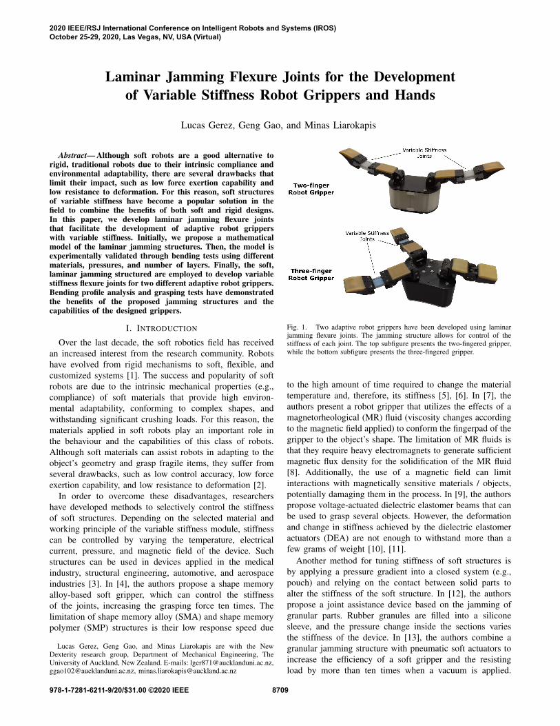
Fig. 1. Two adaptive robot grippers have been developed using laminarjamming flexure joints. The jamming structure allows for control of thestiffness of each joint. The top subfigure presents the two-fingered gripper,while the bottom subfigure presents the three-fingered gripper.
to the high amount of time required to change the materialtemperature and, therefore, its stiffness [5], [6]. In [7], theauthors present a robot gripper that utilizes the effects of amagnetorheological (MR) fluid (viscosity changes accordingto the magnetic field applied) to conform the fingerpad of thegripper to the object’s shape. The limitation of MR fluids isthat they require heavy electromagnets to generate sufficientmagnetic flux density for the solidification of the MR fluid[8]. Additionally, the use of a magnetic field can limitinteractions with magnetically sensitive materials / objects,potentially damaging them in the process. In [9], the authorspropose voltage-actuated dielectric elastomer beams that canbe used to grasp several objects. However, the deformationand change in stiffness achieved by the dielectric elastomeractuators (DEA) are not enough to withstand more than afew grams of weight [10], [11].
Another method for tuning stiffness of soft structures isby applying a pressure gradient into a closed system (e.g.,pouch) and relying on the contact between solid parts toalter the stiffness of the soft structure. In [12], the authorspropose a joint assistance device based on the jamming ofgranular parts. Rubber granules are filled into a siliconesleeve, and the pressure change inside the sections variesthe stiffness of the device. In [13], the authors combine agranular jamming structure with pneumatic soft actuators toincrease the efficiency of a soft gripper and the resistingload by more than ten times when a vacuum is applied.
2020 IEEE/RSJ International Conference on Intelligent Robots and Systems (IROS)October 25-29, 2020, Las Vegas, NV, USA (Virtual)
978-1-7281-6211-9/20/$31.00 ©2020 IEEE 8709

Granular jamming structures, however, do not withstand hightensile and bending loads, having limited applications. Onthe other hand, laminar jamming structures (stack of flexiblelayers to which an external pressure gradient is applied) canoffer more resistance to tensile stress and tensile bendingstress due to the direction of applied frictional forces beingparallel to these stresses. This can be seen when comparingjamming structures for the design of manipulators, as a lam-inar jamming manipulator [14] is capable of resisting morethan 2 times the load of a granular jamming manipulator[15]. In [16], the authors describe several applications oftunable stiffness using laminar jamming structures. Theseapplications can range from the development of variablestiffness furniture to the creation of variable softness sportsshoes. In [17], the authors incorporate laminar jamming intosoft, tendon-driven fingers to improve their force exertioncapabilities during grasping. In [18], the authors proposea laminar jamming structure to tune dynamic responses ofrobotic systems by increasing stiffness by more than 20 timeswhen a vacuum is applied to the envelope.
In this paper, we propose laminar jamming flexure jointsthat can be used to develop adaptive robot grippers withvariable stiffness. Initially, we discuss the designs and themathematical modelling. Then, the model is experimentallyvalidated through bending tests using different materials,pressures, and number of layers. The efficiency of theproposed jamming structures is experimentally validated bycontrolling the stiffness of the flexure joints of two adaptiverobot grippers (Fig. 1). Bending profile analysis and graspingtests were performed to evaluate the effect of the jammingstructures on the capabilities of the grippers.
The rest of the paper is organized as follows: SectionII presents the designs, Section III details the experimentalsetup used and presents the results, while Section IV con-cludes the paper and discusses future directions.
II. SOFT LAMINAR JAMMING STRUCTURE
In this section, we present the designs and the modellingof the laminar jamming structures.
A. Design
The soft, laminar jamming structure was designed toachieve multiple stiffnesses by applying a pressure gradientinto the system. The structure is composed of a soft pouchwith several thin layers inside it (see Fig. 2). When thevacuum is applied inside the pouch, the high friction betweenlayers increase the yield point of the entire structure. Thepouches tested in this study are made out of silicone rubber(Smooth-On Dragon Skin 30), and their walls are 1 mmthick. The bending tests used pouches 142 mm long, 11 mmhigh, and 26 mm wide.
There are several parameters that can change the perfor-mance of laminar jamming structures [19]. In this study,we verify the effect of the layers’ material, the numberof layers, and the system pressure in the behaviour ofthe jamming structure. Four different layer materials wereanalyzed (see Fig. 3): white paper (0.1 mm thick), sandpaper
Fig. 2. The soft laminar jamming structure can achieve multiple stiffnessesby applying a pressure gradient into the system. The structure is composedof a soft pouch made out of silicone rubber (Smooth-On Dragon Skin 30),an air outlet, and several thin layers. When the vacuum is applied insidethe pouch, the high friction between layers increase the yield point of theentire structure.
Fig. 3. The soft laminar jamming structure was tested with four differenttypes of layers: white paper (80 gsm), sandpaper P150 grit (coarse),sandpaper P360 grit (medium), and sandpaper P800 grit (fine). Also, threedifferent layer thicknesses were analyzed: 4 mm, 6 mm, and 8 mm. Thedescribed parameters were tested in three vacuum pressures: 30 kPa, 50kPa, and 70 kPa.
P800 (0.20 mm thick), sandpaper P360 (0.22 mm thick),and sandpaper P150 (0.32 mm thick). These materials werechosen because they provide high friction between the layers,which results in stiffer jamming structures. Also, the use ofoff-the-shelf materials is important for the replication of thisstudy by others and for further analysis. Three different totalthicknesses were also analyzed: 4 mm, 6 mm, and 8 mm. Thedescribed parameters were tested in three vacuum pressures:30 kPa, 50 kPa, and 70 kPa.
B. Analytical Modelling
The correct estimation of the limits of the jammingstructure in terms of stiffness capabilities is highly importantin order to verify the best jamming structure that fits thedesired application. For this reason, an analytical modelwas developed to estimate the performance of the jamming
8710

Fig. 4. The proposed model is based on the behaviour of compositebeams. The maximum load that can be applied to the jamming structureuntil its plastic deformation starts, is achieved right before the layers slidebetween each other. Thus, the shear stress calculated should be less than themaximum frictional stress to guarantee that the layers will not slip betweeneach other. The maximum shear stress between layers is obtained close to thesymmetry plane / neutral axis (between the center layer and the adjacentlayer). When the number of layers is even, the maximum shear stress isapplied to the interface of the two middle layers where the symmetry planeis located. When the number of layers is odd, the maximum shear stress isapplied to the closest interface to the symmetry plane.
structure according to the available vacuum pressure of thesystem. The proposed model can be used to improve thedesign of the actuator by testing multiple materials and ge-ometries (for future design iterations), without manufacturingphysical prototypes. Also, it can be used for controlling thestiffness of a robotic system in a closed-loop manner. Finite-element simulations can become computationally expensivewith jamming structures that have numerous layers [20].
One of the most popular tests to analyze the properties andbehaviour of materials is the three-point flexural test. Thus,we propose an analytic model considering the conditions ofthis test. We propose a model based on the behaviour ofcomposite beams. A composite beam is composed of twoor more elemental structural forms, or different materialsjoined together. In this model, we assume that the materialis uniform and that the jamming structure is symmetric.Previous experiments with jamming structures [20], havedemonstrated that the maximum vertical elastic deformationof this kind of structure is less than 10% of the length of thelayers. Thus, the Euler–Bernoulli beam theory [21] can beadopted to model this structure. The problem can be dividedinto two different parts: before and after the layers slidebetween each other. The maximum load that can be appliedto the jamming structure until its plastic deformation starts,is achieved right before the layers slide between each other.
Considering a force F being applied at the center of thestructure during a three-point flexural test (Fig. 4), the shearstress, τ , can be calculated by
τ =V QIeqb
, (1)
Where V is the shear force at the point, Q is the firstmoment of area, I is the equivalent moment of inertia ofthe entire cross-section area, and b is the width of the layer.The shear stress calculated should be less than the maximumfrictional stress to guarantee that the layers will not slipbetween each other. According to Eq. 1, the maximum shearstress in between layers is obtained close to the symmetryplane / neutral axis (between the center layer and the adjacentlayer). The frictional stress, τ f , can be calculated by dividingthe friction force by the area of the interface, Al , using theEq. 2. More precisely, µs is defined as the static frictioncoefficient between both layers. The ratio between the normalforce, N f , and the area of the interface can be written as thevacuum pressure, Pc, in the jamming structure. The weightof layers was neglected in the normal force calculation.
τ f =µsN f
Al= µsPc (2)
Thus, the maximum shear force, Vyield , before the layersslip in the interface can be calculated using the followingequation (Eq. 3). The shear force can also be written in termsof the yield force, Fyield , as follows
Vyield =Fyield
2=
µsPcIbQ
(3)
The first moment of area, Q, when the structure is undervacuum, can be calculated (for n number of layers) in theinterface with the highest shear stress (Fig. 4). If the numberof layers is odd, the moment of area is defined as
Qodd =(n2 −1)bt2
l8
, (4)
Where tl is the thickness of each layer. If the number oflayers is even, the moment of area is defined as
Qeven =n2bt2
l8
. (5)
The equivalent moment of inertia of the structure undervacuum can be calculated using Eq. 6, as follows
I =n3bt3
l12
(6)
Combining Eq. 4 or Eq. 5 and Eq. 6 in Eq. 3, the yieldforce for a three-point flexural test can be written as
Feven =4nbtl µsPc
3, (7)
For an even number of layers, and
Fodd =4n3btl µsPc
3(n2 −1), (8)
For an odd number of layers. Analyzing Eq. 7 and Eq. 8,it can be noticed that the force required to slide the layers ofthe jamming structure (yield force) is directly proportional
8711

Fig. 5. This adaptive, variable stiffness, robotic finger consists of a laminarjamming flexure joint (based on a vacuum pouch made from SmoothOnDragon skin 30) with ten P150 grit sandpaper layers, two urethane end caps(SmoothOn PMC-780), and two phalanges. The white dashed line showsthe tendon routing channels of the finger.
to the friction coefficient between the layers and the vacuumpressure applied to the system. Moreover, the yield forceincreases with the number of layers, and when very thinlayers are used, the yield force equations for odd and evennumber of layers provide similar results.
C. Adaptive Grippers with Variable Stiffness
Adaptive robot grippers are a popular solution for per-forming object grasping and dexterous manipulation dueto their ability to execute stable grasps even under objectpose uncertainties, their low complexity, robustness, andaffordability. Adaptive robot grippers are able to replacecomplex, heavy, and expensive robot devices that requiresophisticated sensing and complicated control laws [22],[23]. Their efficiency is due to the structural compliance andthe underactuation that allow them to adjust their graspingpostures according to the object geometry, maximizing thearea of contact with the object [24], [25]. Despite theoutstanding performance, adaptive grippers have also cer-tain drawbacks and limitations. An underactuated design ischaracterized by a significant post-contact reconfigurationof the hand object system that imposes a parasitic objectmotion. This reconfiguration occurs until the system reachesan equilibrium configuration [26], and it may compromisethe pinch grasping capabilities of the system. For this reason,adaptive hands are typically used for full / power grasps,and they are not very efficient in the execution of pinchgrasps. Although underactuated fingers can be optimized forjoint stiffness, link length ratios, and tendon routing forspecific configurations, this cannot prevent reconfigurationin all finger configurations and contact force points. By im-plementing variable stiffness flexure joints, a higher numberof finger configurations / poses can be achieved, enablingmore manipulation profiles to be executed by compliant andunderactuated robot hands.
In a previous work [27], we have demonstrated that duringa pinch grasp, a significant amount of the applied load iswasted on reconfiguration. This reduces the available finger-tip force that could be applied to the object, compromising
the overall grasp efficiency. By adjusting the stiffness ofthe joints, it is possible to increase the force applied bythe gripper in pinch grasps. Thus, in this paper, we havedeveloped two adaptive robot grippers (a two-fingered anda three-fingered design) that employ the proposed laminarjamming flexure joints to increase their grasping capabilities.
1) A Two Fingered Adaptive Robot Gripper: The firstadaptive robot gripper consists of two robot fingers with twophalanges each and a robot base. Artificial tendons connectthe fingertip of the robotic fingers to motors (DynamixelXM430-W350-R) located at the gripper base (see Fig. 5).The finger structure is inspired by the Model T42 gripper[28]. The joints of the fingers consist of a set of pinjoints at the metacarpophalangeal (MCP) joints, and modular,laminar jamming flexure structures that act as the distalinterphalangeal (DIP) joints. This allows for the exertion ofhigh pinch grasp forces, while ensuring that the stiffness ofthe joints does not reduce the efficiency of the power grasp.The jamming flexure joints consist of ten P150 grit sandpaperlayers encased in a silicone vacuum pouch (SmoothOnDragon Skin 30). Urethane end caps (SmoothOn PMC-780)fitted to the ends of the pouch are clamped to the edges ofthe finger phalanges to distribute load through the laminarlayer while providing a tight seal. The described finger andits construction can be seen in Fig. 5. A single vacuumpressure actuator is used to jam the layers of both fingers,enabling variable stiffness at the DIP joint. This providesincreased controllability over finger poses while maintainingthe compliant attributes of conventional flexure joints.
2) A Three Fingered Adaptive Robot Gripper: The secondadaptive robot gripper consists of three robot fingers withtwo phalanges each and a robot base. The design employsthe same tendon-driven actuation scheme and similar motors(Dynamixel MX28-AR) located at the gripper base. Thefinger structure is inspired by the Model O gripper [28]. Thejoints of the fingers consist once again of a set of pin joints atthe MCP joints and modular, laminar jamming flexure jointsfor the DIP joints. The laminar jamming flexure joints aresimilar to the two-fingered gripper jamming joints and followthe same working principle. Both the two-fingered gripperand the three-fingered gripper are presented in Fig. 1.
III. EXPERIMENTS AND RESULTS
The experiments that were conducted to assess the per-formance of the jamming structure were divided into fourdifferent parts. The first part of the experiments focusedon evaluating the laminar jamming structure in differentscenarios and validating the proposed mathematical modelof the mechanism. The second experiment focused on eval-uating the effect of the proposed jamming structure in thebending profile of the robotic fingers. The third part of theexperiments assessed the grasping forces of a gripper in dif-ferent scenarios employing the proposed jamming structure.Finally, the fourth part of the experiments focused on theevaluation of the grasping capabilities of the grippers.
8712

Fig. 6. Laminar jamming structural force vs deflection tests. Subfigure a),shows the three-point flexural test executed using a materials testing machine(Instron 5567) for four different materials, three different thicknesses, andthree different pressures. Subfigure b), shows the relationship between thestructural deflection and the force for the white paper, the sandpaper P150,the sandpaper P360, and the sandpaper P800, for a combined layer thicknessof 8 mm under a pressure of 70 kPa. The force resistance increases with thefriction coefficient between the layers. Subfigure c), shows the relationshipbetween the resistance force and the combined thickness of the layers forthe sandpaper P150 material at a pressure of 70 kPa. Subfigure d), shows theeffect of different pressures on the jamming structure for sandpaper P800and a combined thickness of the layers of 8 mm.
A. Bending Tests
The first part of the experiments tested different laminarjamming structures by varying the total thickness of thelayers (4 mm, 6 mm, and 8 mm) and the layers mate-rials (white paper, sandpaper P150, sandpaper P360, andsandpaper P800). All the different tested conditions werecompared to the proposed model (Section II-B). Also, itwas tested under vacuum pressures of 30 kPa, 50 kPa, and70 kPa. The laminar jamming structure was characterizedusing a materials testing machine (Instron 5567, InstronLimited, UK) through a three-point flexural test (Fig. 6-a). The experiments followed the guidelines of the standardASTM D790-17 Procedure B (Standard Test Methods forFlexural Properties of Unreinforced and Reinforced Plasticsand Electrical Insulating Materials). A total of five trials ofeach scenario were tested. A 12V vacuum pump was used toapply the pressure gradient and a pressure gauge was usedto control the system pressure during the experiments.
TABLE ISTATIC FRICTION COEFFICIENTS (µs) AND STANDARD DEVIATION (SD)
FOR THE MATERIALS TESTED: WHITE PAPER, SANDPAPER P150(COARSE), SANDPAPER P360 (MEDIUM), AND SANDPAPER P800 (FINE).
Layer Material µs SDWhite paper 0.38 0.02
Sandpaper P800 0.93 0.03Sandpaper P360 1.15 0.04Sandpaper P150 1.32 0.04
Fig. 7. The joint tracking experiment focused on evaluating the effect ofthe proposed jamming structure in the bending profile of the robotic fingers.Vacuum pressures of 30 kPa, 50 kPa, and 70 kPa at the DIP joint wereused. The results demonstrate that the jamming structure can control thejoint angle by applying different vacuum pressure at the jamming structure.
In order to compare the bending test results and theanalytical model, it was required to estimate the frictioncoefficient between the layers of the jamming structure.Thus, friction coefficient tests were performed for all testedmaterials following the guidelines of the standard ASTMG115 (Standard Guide for Measuring and Reporting FrictionCoefficients). The friction coefficients obtained are reportedin Table I. Fig. 6 illustrates the results obtained during theexperiments. It can be noticed that the yield force of the jam-ming structure increases as the friction coefficient betweenthe layers (Fig. 6-b), the number of layers (Fig. 6-c), and thevacuum pressure increase (Fig. 6-d). The sandpaper P150jamming structure offered the best result in terms of forceresistance. Also, it was noticed that the motion between thelayers gradually changes the ratio between the applied forceand the deflection of the structure. The yield force calculatedby the proposed analytical model estimated the layer slippingregion. The model can be used to improve the design of thejamming structure, testing multiple materials and geometries(for future design iterations) without manufacturing physicalprototypes. The model can be also used for controlling themaximum force of jamming structure in closed-loop systemsby varying the pouch pressure.
B. Joint Tracking Experiment
The second experiment focused on evaluating the effectof the proposed jamming structure in the bending profile ofthe robotic fingers. More precisely, it involved the analysisof the bending profile of the finger of the gripper undervacuum pressures of 30 kPa, 50 kPa, and 70 kPa at the
8713

Fig. 8. The three-fingered adaptive robotic gripper with the laminar jamming based flexure joints while executing grasping experiments with everydayobjects. The ability of the jamming flexure joints to vary their stiffnesses allows the gripper to bend and grasp with different finger poses.
Fig. 9. Gripper motion when the jamming structure is activated (70 kPa)and when it is unjammed (0 kPa). The change in joint behaviour allows thegripper to grasp a wider range of objects by planning the gripper motionprior to the grasp.
DIP joint. The experiment was conducted using an opticalmotion capture system with eight cameras (Vicon MotionSystem Ltd., UK) to capture the range of motion of onefinger in all four scenarios. Five reflective markers wereattached at the side of the robot finger to track its bendingprofile. In all the trials, the motor was set to the samedisplacement to guarantee that the tendon had the samedisplacement independently of the pressure in the jammingstructure. The experiment was repeated ten times for eachvacuum pressure. Fig. 7 shows DIP joint values for eachscenario tested. The results demonstrate that the bendingprofile of the finger is affected by the vacuum pressure in thejamming structure. When the jamming structure is not undervacuum the DIP joint bends more than 20◦ before closingcompletely. Once a vacuum is applied (70 kPa), the jointangle flexion is reduced to less than 5◦. However, the fingerDIP joint angle trajectory is similar across differing appliedvacuum pressures (30 kPa, 50 kPa, and 70 kPa) as the laminarjamming structure will remain at the same stiffness, but theyield force will be altered under negative pressure. Hence,the maximum applied pinch contact force that can be appliedcan be controlled by altering the yield force of the laminarjamming joint. Fig. 9 shows the gripper motion when thejamming structure is activated and when it is unjammed (0
TABLE IIPINCH FORCE RESULTS FOR THE LAMINAR JAMMING FLEXURE JOINT
WITH SANDPAPER P150 GRIT LAYERS UNDER DIFFERENT PRESSURE
VALUES.
Vacuum Pressure Max Pinch Force (N)0 kPa 0.8530 kPa 1.1950 kPa 1.5370 kPa 2.39
kPa). This behaviour allows the proposed robotic grippers toapproach the objects to be grasped with different fingertiporientations and to execute different grasping strategies. Italso allows the robotic gripper to successfully grasp a widerrange of everyday objects by planning the gripper motionprior to execution of the grasp.
C. Grasping Force Experiment
The third part of the experiments evaluated the effectof the jamming structure on the pinch forces exerted bya robotic gripper. The experiment involved pinch graspingof a dynamometer under different pressures in the jammingstructure. A Biopac MP36 data acquisition unit (BiopacSystems, Inc., California, USA) was used with the SS25LAdynamometer to measure the forces exerted in each scenario.The motors were set to the same displacement at all times.Fig. 9 shows the behaviour of the gripper while pinchgrasping the dynamometer at the pressure of 0 kPa, 30 kPa,50 kPa, and 70 kPa in the jamming structure. A total of threetrials were executed for each scenario. The results shownin Table II, demonstrate that the gripper can exert higherpinch forces when the jamming structure is subjected tohigher pressures (an increase of almost three times in pinchforces was observed compared to a pressure of 0 kPa). Whenunder vacuum, the jamming structure reduces significantlythe amount of motor load wasted on finger reconfiguration,resulting in higher pinch forces. Higher pinch forces meanthat heavier objects can be grasped and, therefore, more taskscan be executed with the proposed gripper.
8714

D. Grasping of Everyday Objects
Finally, the fourth part of the conducted experimentsfocused on grasping everyday objects with the proposedgrippers. Instances of the experiments conducted with thethree-fingered gripper grasping a bleach bottle, a drill, afootball, a plastic apple, and a screwdriver can be foundin Fig. 8. More experiments involving both grippers can befound in the accompanying video.
E. Video Demonstration
A video containing the device description and the experi-ments can be found at the following URL:
http://newdexterity.org/jamming
IV. CONCLUSIONS AND FUTURE DIRECTIONS
In this paper, we proposed laminar jamming flexure jointsthat can be used to develop adaptive robot grippers withvariable stiffness. The efficiency of the proposed jammingmechanism was experimentally validated through three dif-ferent types of experiments. The soft laminar jamming struc-ture was also tested in a real application by incorporating itinto two different robot gripper designs, conducting graspingforce experiments and grasping experiments with everydayobjects. The experimental results demonstrate that the jam-ming structure can be efficiently used to tune the stiffnessof flexure joints and that it can increase the capabilitiesof adaptive grippers: i) improving the exerted pinch graspforces and ii) controlling the bending profile, increasing thenumber of possible grasping strategies for various objects.Although laminar jamming joints provide increased dexter-ity when incorporated into adaptive grippers, the variablestiffness joints have low repeatability and durability whenthey are fabricated with materials like paper and sandpaper.Such materials exhibit significant ware (when they are bent)that results in reduced surface friction between layers orplastic deformation. Regarding future directions, we plan tointegrate the laminar jamming structure to a five-fingeredadaptive robotic hand with an embedded vacuum pump totune the stiffness of the joints in a closed-loop manner.
REFERENCES
[1] S. Kim, C. Laschi, and B. Trimmer, “Soft robotics: a bioinspiredevolution in robotics,” Trends in biotechnology, vol. 31, no. 5, pp.287–294, 2013.
[2] P. Polygerinos, N. Correll, S. A. Morin, B. Mosadegh, C. D. Onal,K. Petersen, M. Cianchetti, M. T. Tolley, and R. F. Shepherd, “Softrobotics: Review of fluid-driven intrinsically soft devices; manufac-turing, sensing, control, and applications in human-robot interaction,”Advanced Engineering Materials, vol. 19, no. 12, p. 1700016, 2017.
[3] L. Wang, Y. Yang, Y. Chen, C. Majidi, F. Iida, E. Askounis, andQ. Pei, “Controllable and reversible tuning of material rigidity forrobot applications,” Materials Today, vol. 21, no. 5, pp. 563–576, 2018.
[4] W. Wang and S.-H. Ahn, “Shape memory alloy-based soft gripper withvariable stiffness for compliant and effective grasping,” Soft robotics,vol. 4, no. 4, pp. 379–389, 2017.
[5] L. Wang, U. Culha, and F. Iida, “A dragline-forming mobile robotinspired by spiders,” Bioinspiration & biomimetics, vol. 9, no. 1, p.016006, 2014.
[6] Y. Yang, Y. Chen, Y. Li, M. Z. Chen, and Y. Wei, “Bioinspired roboticfingers based on pneumatic actuator and 3d printing of smart material,”Soft robotics, vol. 4, no. 2, pp. 147–162, 2017.
[7] A. Pettersson, S. Davis, J. Gray, T. Dodd, and T. Ohlsson, “Designof a magnetorheological robot gripper for handling of delicate foodproducts with varying shapes,” Journal of Food Engineering, vol. 98,no. 3, pp. 332–338, 2010.
[8] T. Nishida, Y. Okatani, and K. Tadakuma, “Development of universalrobot gripper using mr α fluid,” International Journal of HumanoidRobotics, vol. 13, no. 04, p. 1650017, 2016.
[9] S. Shian, K. Bertoldi, and D. R. Clarke, “Dielectric elastomer based“grippers” for soft robotics,” Advanced Materials, vol. 27, no. 43, pp.6814–6819, 2015.
[10] G.-K. Lau, K.-R. Heng, A. S. Ahmed, and M. Shrestha, “Dielectricelastomer fingers for versatile grasping and nimble pinching,” AppliedPhysics Letters, vol. 110, no. 18, p. 182906, 2017.
[11] J. Shintake, B. Schubert, S. Rosset, H. Shea, and D. Floreano, “Vari-able stiffness actuator for soft robotics using dielectric elastomer andlow-melting-point alloy,” in 2015 IEEE/RSJ International Conferenceon Intelligent Robots and Systems (IROS). IEEE, 2015, pp. 1097–1102.
[12] S. Hauser, M. Robertson, A. Ijspeert, and J. Paik, “Jammjoint: Avariable stiffness device based on granular jamming for wearable jointsupport,” IEEE Robotics and Automation Letters, vol. 2, no. 2, pp.849–855, 2017.
[13] Y. Wei, Y. Chen, T. Ren, Q. Chen, C. Yan, Y. Yang, and Y. Li, “A novel,variable stiffness robotic gripper based on integrated soft actuating andparticle jamming,” Soft Robotics, vol. 3, no. 3, pp. 134–143, 2016.
[14] Y. Kim, S. Cheng, S. Kim, and K. Iagnemma, “Design of a tubularsnake-like manipulator with stiffening capability by layer jamming,”in 2012 IEEE/RSJ International Conference on Intelligent Robots andSystems, 2012, pp. 4251–4256.
[15] N. G. Cheng, M. B. Lobovsky, S. J. Keating, A. M. Setapen, K. I.Gero, A. E. Hosoi, and K. D. Iagnemma, “Design and analysis of arobust, low-cost, highly articulated manipulator enabled by jamming ofgranular media,” in 2012 IEEE International Conference on Roboticsand Automation, 2012, pp. 4328–4333.
[16] J. Ou, L. Yao, D. Tauber, J. Steimle, R. Niiyama, and H. Ishii,“jamsheets: thin interfaces with tunable stiffness enabled by layerjamming,” in Proceedings of the 8th International Conference onTangible, Embedded and Embodied Interaction, 2014, pp. 65–72.
[17] Y. Gao, X. Huang, I. S. Mann, and H.-J. Su, “A novel variable stiffnesscompliant robotic gripper based on layer jamming,” ASME Journal ofMechanisms and Robotics, vol. 12, no. 5, 2020.
[18] Y. S. Narang, A. Degirmenci, J. J. Vlassak, and R. D. Howe,“Transforming the dynamic response of robotic structures and systemsthrough laminar jamming,” IEEE Robotics and Automation Letters,vol. 3, no. 2, pp. 688–695, 2017.
[19] V. Wall, R. Deimel, and O. Brock, “Selective stiffening of softactuators based on jamming,” in 2015 IEEE International Conferenceon Robotics and Automation (ICRA). IEEE, 2015, pp. 252–257.
[20] Y. S. Narang, J. J. Vlassak, and R. D. Howe, “Mechanically versa-tile soft machines through laminar jamming,” Advanced FunctionalMaterials, vol. 28, no. 17, p. 1707136, 2018.
[21] O. Bauchau and J. Craig, “Euler-bernoulli beam theory,” in Structuralanalysis. Springer, 2009, pp. 173–221.
[22] L. Birglen, T. Laliberte, and C. M. Gosselin, Underactuated robotichands. Springer, 2007, vol. 40.
[23] D. M. Aukes, B. Heyneman, J. Ulmen, H. Stuart, M. R. Cutkosky,S. Kim, P. Garcia, and A. Edsinger, “Design and testing of a selectivelycompliant underactuated hand,” The International Journal of RoboticsResearch, vol. 33, no. 5, pp. 721–735, 2014.
[24] A. M. Dollar and R. D. Howe, “A robust compliant grasper via shapedeposition manufacturing,” IEEE/ASME transactions on mechatronics,vol. 11, no. 2, pp. 154–161, 2006.
[25] T. Laliberte, L. Birglen, and C. Gosselin, “Underactuation in roboticgrasping hands,” Machine Intelligence & Robotic Control, vol. 4, no. 3,pp. 1–11, 2002.
[26] M. V. Liarokapis and A. M. Dollar, “Post-contact, in-hand objectmotion compensation with adaptive hands,” IEEE Transactions onAutomation Science and Engineering, 2016.
[27] L. Gerez, G. Gao, and M. Liarokapis, “Employing magnets to improvethe force exertion capabilities of adaptive robot hands in precisiongrasps,” in 2019 IEEE/RSJ International Conference on IntelligentRobots and Systems (IROS), Nov 2019, pp. 7630–7635.
[28] R. Ma and A. Dollar, “Yale openhand project: Optimizing open-sourcehand designs for ease of fabrication and adoption,” IEEE Robotics &Automation Magazine, vol. 24, no. 1, pp. 32–40, 2017.
8715