Lagrangian simulation of the unsteady near field...
24
Lagrangian simulation of the unsteady near field dynamics of planar buoyant plumes M. C. Soteriou, a) Y. Dong, and B. M. Cetegen Department of Mechanical Engineering, University of Connecticut, Storrs, Connecticut 06269-3139 ~Received 7 November 2001; accepted 15 May 2002; published 5 August 2002! The unsteady dynamics of planar plumes is investigated numerically with particular emphasis on the pulsating instability characterizing the source ~nozzle! near field. This instability manifests itself as the periodic shedding of vortical structures from the nozzle. The Lagrangian Transport Element Method is used to provide high resolution two-dimensional simulations of the unaveraged variable density flow. Comparison with experimental results verifies that the simulations capture the plume instantaneous behavior and reproduce the pulsation frequency. The latter is controlled by a Strouhal–Richardson number correlation which implies that the instability is inviscid in nature with a frequency that is mainly dependent on the gravitational acceleration and the nozzle width, f ;A g / w . The presence of a horizontal wall surrounding the nozzle exit does not affect these results. Numerical results indicate that transition from nonpulsatile to pulsatile behavior obeys a Reynolds– Richardson number correlation of the form Re;Ri 20.627 implying a balance between buoyant and viscous forces. Arguments based on vorticity dynamics trace the origin of the instability to the mechanism of vorticity generation by buoyancy. In the nonpulsatile flow, the circulation generated by buoyancy increases monotonically with height at a rate that is approximately constant. This arrangement can be altered via perturbations that create local circulation maxima and can lead to vortex formation. Once a first vortex pair is created, a subsequent pair precipitates via a mechanism that yields circulation maxima near the nozzle exit through the interaction of the local vorticity generation by buoyancy with the strain field induced by the preceding vortex pair. This mechanism is complex enough to suggest that simple theoretical models that predict the pulsation frequency are unlikely. It does help explain, however, the relative simplicity of the functionality of the frequency and its lack of sensitivity on a variety of boundary conditions and external parameters. © 2002 American Institute of Physics. @DOI: 10.1063/1.1491248# I. INTRODUCTION Buoyant plumes, the flows that develop when a fluid is exposed to an environment of different density under condi- tions where buoyancy dominates the processes governing fluid motion, occur frequently in nature ~atmospheric up- drafts, deep sea thermals, magma plumes, etc.! and in engi- neering practice ~release of effluents from smokestacks, flows over hot surfaces, in storage tanks, etc.!. These flows are susceptible to a variety of unstable behaviors that are characterized by very complicated rotational motions, for ex- ample, the convoluted motion traced by cigarette smoke. While the rotationality of these flows can be traced to a com- mon physical mechanism, the manifestation of each type of unstable behavior depends on flow parameters, the geometri- cal features of the source of the buoyant fluid and the pres- ence of perturbations. In this paper we focus on the flow in the neighborhood of the source, i.e., the flow near field, and we investigate a particular unstable behavior that is charac- terized by a repetitive shedding of coherent vortical struc- tures at a well prescribed frequency that shows a strong de- pendence on the size of the source. 1,2 This pulsating instability has been identified as being similar to the puffing behavior seen in the near field of pool fires and buoyant diffusion flames. 3 The vortical structures arising from this instability, control the entrainment of the ambient fluid in the source near field. In the case of flames and fires, this implies a control of the oxidizer and fuel distributions and hence a strong impact on the combustion process. 4 The pulsating instability should be distinguished from far field instabilities that occur far downstream, some of which have received attention in the past. 5 These latter insta- bilities amplify different frequencies from that of the pulsat- ing instability and are much more dependent on the presence and character of perturbations. Even when one concentrates in the nozzle near field, however, a number of unsteady be- haviors may be witnessed that do not conform to the pulsa- tions described above. For example, when the buoyancy is very dominant, the rotational flow may interact very strongly with the source geometry ~e.g., the flow may form a recircu- lation zone in the vicinity of the source! leading to a break- down of the organized pulsating behavior noted above and to unsteady behaviors that are very complicated. At the other extreme, when the buoyancy is weak, the flow in the near field responds to a different set of instabilities that are char- acteristic of inertial jets. 6 In addition, in the case of buoyant flames it has recently been shown that the near field flow may even temporally bifurcate between different instability modes. 7,8 Thus, it is clarified at the outset that the pulsating a! Present address: United Technologies Research Center, East Hartford, CT 06108. PHYSICS OF FLUIDS VOLUME 14, NUMBER 9 SEPTEMBER 2002 3118 1070-6631/2002/14(9)/3118/23/$19.00 © 2002 American Institute of Physics
Transcript of Lagrangian simulation of the unsteady near field...

PHYSICS OF FLUIDS VOLUME 14, NUMBER 9 SEPTEMBER 2002
Lagrangian simulation of the unsteady near field dynamics of planarbuoyant plumes
M. C. Soteriou,a) Y. Dong, and B. M. CetegenDepartment of Mechanical Engineering, University of Connecticut, Storrs, Connecticut 06269-3139
~Received 7 November 2001; accepted 15 May 2002; published 5 August 2002!
The unsteady dynamics of planar plumes is investigated numerically with particular emphasis on thepulsating instability characterizing the source~nozzle! near field. This instability manifests itself asthe periodic shedding of vortical structures from the nozzle. The Lagrangian Transport ElementMethod is used to provide high resolution two-dimensional simulations of the unaveraged variabledensity flow. Comparison with experimental results verifies that the simulations capture the plumeinstantaneous behavior and reproduce the pulsation frequency. The latter is controlled by aStrouhal–Richardson number correlation which implies that the instability is inviscid in nature witha frequency that is mainly dependent on the gravitational acceleration and the nozzle width,f;Ag/w. The presence of a horizontal wall surrounding the nozzle exit does not affect these results.Numerical results indicate that transition from nonpulsatile to pulsatile behavior obeys a Reynolds–Richardson number correlation of the form Re;Ri20.627 implying a balance between buoyant andviscous forces. Arguments based on vorticity dynamics trace the origin of the instability to themechanism of vorticity generation by buoyancy. In the nonpulsatile flow, the circulation generatedby buoyancy increases monotonically with height at a rate that is approximately constant. Thisarrangement can be altered via perturbations that create local circulation maxima and can lead tovortex formation. Once a first vortex pair is created, a subsequent pair precipitates via a mechanismthat yields circulation maxima near the nozzle exit through the interaction of the local vorticitygeneration by buoyancy with the strain field induced by the preceding vortex pair. This mechanismis complex enough to suggest that simple theoretical models that predict the pulsation frequency areunlikely. It does help explain, however, the relative simplicity of the functionality of the frequencyand its lack of sensitivity on a variety of boundary conditions and external parameters. ©2002American Institute of Physics.@DOI: 10.1063/1.1491248#
id
ni
s
aexkm
ere
ianraucd
ng
antselies
a
mof
t-nceatesbe-lsa-y isly
-
d toherearar-towityng
rtfo
I. INTRODUCTION
Buoyant plumes, the flows that develop when a fluidexposed to an environment of different density under contions where buoyancy dominates the processes goverfluid motion, occur frequently in nature~atmospheric up-drafts, deep sea thermals, magma plumes, etc.! and in engi-neering practice~release of effluents from smokestackflows over hot surfaces, in storage tanks, etc.!. These flowsare susceptible to a variety of unstable behaviors thatcharacterized by very complicated rotational motions, forample, the convoluted motion traced by cigarette smoWhile the rotationality of these flows can be traced to a comon physical mechanism, the manifestation of each typeunstable behavior depends on flow parameters, the geomcal features of the source of the buoyant fluid and the pence of perturbations. In this paper we focus on the flowthe neighborhood of the source, i.e., the flow near field,we investigate a particular unstable behavior that is chaterized by a repetitive shedding of coherent vortical strtures at a well prescribed frequency that shows a strongpendence on the size of the source.1,2 This pulsatinginstability has been identified as being similar to the puffi
a!Present address: United Technologies Research Center, East HaCT 06108.
3111070-6631/2002/14(9)/3118/23/$19.00
si-ng
,
re-
e.-
oftri-s-ndc--e-
behavior seen in the near field of pool fires and buoydiffusion flames.3 The vortical structures arising from thiinstability, control the entrainment of the ambient fluid in thsource near field. In the case of flames and fires, this impa control of the oxidizer and fuel distributions and hencestrong impact on the combustion process.4
The pulsating instability should be distinguished frofar field instabilities that occur far downstream, somewhich have received attention in the past.5 These latter insta-bilities amplify different frequencies from that of the pulsaing instability and are much more dependent on the preseand character of perturbations. Even when one concentrin the nozzle near field, however, a number of unsteadyhaviors may be witnessed that do not conform to the putions described above. For example, when the buoyancvery dominant, the rotational flow may interact very strongwith the source geometry~e.g., the flow may form a recirculation zone in the vicinity of the source! leading to a break-down of the organized pulsating behavior noted above anunsteady behaviors that are very complicated. At the otextreme, when the buoyancy is weak, the flow in the nfield responds to a different set of instabilities that are chacteristic of inertial jets.6 In addition, in the case of buoyanflames it has recently been shown that the near field flmay even temporally bifurcate between different instabilmodes.7,8 Thus, it is clarified at the outset that the pulsatird,
8 © 2002 American Institute of Physics

lann
elfseje
eledabseanr
e
mei-alsalyzliosicffe
ghthin-uoogrpe
tillor
omieadeo
w
mne
tectsttointa
si
erem-sInhe-
eri-heul-
an-seds.na-rentusnara-
ofdf
ngstheedcalw-
ne/la-
thesuch
ityitsees
er,the
o-of
itythe
b-
n-notta-
he, onure.ons,jec-
on
en-
3119Phys. Fluids, Vol. 14, No. 9, September 2002 Lagrangian simulation of unsteady near field dynamics
flow under investigation here occurs within a particurange of flow parameters, under conditions where buoyais dominant but not extremely so. This range of conditiohowever is wide enough for this instability to manifest itsfrequently in nature for both plumes and flames. Conquently, the pulsating/puffing instability has been the subof much research in the past.
The majority of the experimental studies have been pformed for plumes/flames emanating from circular nozzand have witnessed the unstable flow in the form of torroivortical structures shedding from the nozzle. The availaliterature is quite extensive in this respect and heavily biatowards buoyant diffusion flames rather than buoyplumes; see, for example, Refs. 3 and 9–12 and bibliogphies therein. For buoyant plume~helium–air! studies seeRefs. 1, 3 and 13. These experimental studies have beffective at quantifying the instability features~frequency ofpulsation, vortical structure description, sensitivity to paraeters, and boundary conditions!. They have helped reinforcthe qualitative similarity of the pulsating instability manfested in buoyant flames and plumes but they havepointed to quantitative differences. For example, it wfound that the frequency of pulsation for flames is simpproportional to the inverse of the square root of the nozdiameter while for plumes it obeys a more complex relatthat relates the nondimensional frequency to the Richardnumber to the exponent 0.38. Semiempirical, semianalytmodels have also been proposed to account for this dience.
The aforementioned experimental studies have hilighted the need for detailed numerical simulations offlow for the development of a comprehensive understandof the origin of the instability. In similarity to the experiments, most numerical studies have focused on the circsource geometry and have employed the axisymmetric cdinate system; see, for example, Refs. 14–18 and bibliophies therein. The first three of these studies are more resentative of the majority of the available studies in that thconsider diffusion flames in which inertial effects are ssignificant compared to buoyancy. The last two studies csider the case where buoyancy dominates and are moreresentative of fires. These latter studies also include sresults for buoyant plumes. All the above numerical studhave been able to capture the essential flow featuresmost have quantitatively reproduced the experimentallytermined pulsation frequency. A fundamental descriptionthe origin and manifestation of the pulsating instability, hoever, has remained elusive.
As a result of the aforementioned experimental and coputational studies, a number of such descriptions have,ertheless, been proposed. Cetegen and Kasper1 have sug-gested that the instability is intrinsic to the flow and is relato a Rayleigh–Taylor destabilization of the sharply contraing region of the flow above the nozzle exit. In contraother studies have suggested that the instability is duebuoyancy modified Kelvin–Helmholtz instability, i.e., onewhich the velocity difference necessary for this inertial insbility is provided by buoyancy.17,19,20 Some studies havetried to shed light on the nature of the instability by clas
rcys
-ct
r-sl
ledt
a-
en
-
os
enonalr-
-eg
larr-a-re-y
n-ep-
esnd-f
-
-v-
d-,a
-
-
fying it as absolute or convective. Controversy ensued has well. By employing classical stability theory and assuing the flow to be locally parallel, Buckmaster and Peter19
and Yuanet al.21 assessed the instability to be convective.contrast, by relying on his experimental results and the toretical arguments of Huerre and Monkewitz,22 Maxworthy7
classified the instability as absolute.In this paper, we present and analyze results of num
cal simulations of the near field of buoyant plumes with tobjective to develop a fundamental understanding of the psating instability and to help resolve some of the discrepcies noted above. In this effort we follow an approach baon a combination of vorticity dynamics and flow kinematicSuch an approach is highly motivated by the rotationalture of the flow and the apparent role played by the cohevortical structures in the nozzle near field. Unlike previoinvestigations, the numerical study is performed in a plageometry, in effect simulating line plumes or plumes emnating from large aspect ratio rectangular nozzles~slots!.These flows exhibit a similar near field pulsation to thatplumes from circular sources2 and, as such, are well suitefor this study. In similarity to the axisymmetric simulation ocircular plumes, in planar plumes the computational saviassociated with the reduction in dimensionality enabledirect solution of the governing equations without the nefor averaging and/or the introduction of phenomenologimodels. An advantage over axisymmetric simulations, hoever, is that the axis of symmetry at the nozzle centerlimidplane is no longer required. As a result, planar simutions can capture asymmetric~lateral! flow oscillations.Recent experimental studies have shown that even incircular source case pulsating flames can experienceoscillations.7,8
Beyond helping us investigate the pulsating instabilcharacteristics, the study of planar plumes is important inown right with applications in line-fires, refrigerator plumcurtains, etc. In contrast to circular plumes, planar plumhave received relatively little attention in the past. Moreovamong the few available studies, the majority deal withfar field behavior of the flow where self-similarity~in themean! is manifested; see, for example, Refs. 23–25. A ntable exception is our recent experimental investigationthe near field oscillatory dynamics of planar plumes2 whichwill be extensively discussed in this paper. Linear stabilanalyses of planar plumes have also been reported inliterature~refer, for example, to the extensive work of Gehart and co-workers, such as in Ref. 26!. These analysesinvoke similarity solutions for the base flow and one dimesionality ~spatial! for the disturbances and, as such, areappropriate for the region very near the source. Computional studies involving the unaveraged simulation of tnonlinear unsteady near field dynamics of planar plumesthe other hand, have not been presented in the literatConsequently, the presentation of results of such simulatiand their detailed analysis, forms another of the major obtives of this study.
The numerical model employed in the study is basedthe Lagrangian Transport Element Method.27 The develop-ment of the model was heavily influenced by the experim

rieinareteuionualthtutent
ntiodonth
otho
–tita-r
,exi
be
ed
isglyor.uidible.
of
atre-
yan
t
air
re
theitten
em
n
ir,
, to
ri-e
or--
co
3120 Phys. Fluids, Vol. 14, No. 9, September 2002 Soteriou, Dong, and Cetegen
tal setup reported in Ref. 2. For example, the two geometinvestigated in that work, namely those of a free standnozzle and of a nozzle with an attached horizontal wallalso simulated numerically in this work. In addition, thboundary conditions for the numerical model were selecto closely match those manifested in the experiment. Resfrom the experimental study are employed in the validatof the numerical model. Once this is accomplished, themerical results are used to shed light on the experimentobserved behavior. Due to this close relation betweennumerical study presented herein and the experimental snoted above, multiple references to the latter occur in thethat follows. For brevity, in these references the experimestudy will simply be referred to as the experiment.
The paper is organized as follows. The formulation anumerical methodology are presented in Sec. II. This secincludes the main assumptions behind the numerical mothe resulting governing equations and boundary conditiand a description of the numerical technique. In Sec. III,numerical results are presented, including the validationthe numerical model and the analysis and discussion ofobtained results. Finally, in Sec. IV the main conclusionsthe paper are summarized.
II. THE NUMERICAL MODEL
A. Formulation
The unsteady buoyant motion of helium or of a heliumair mixture that flows from a rectangular, large aspect ranozzle into a stagnant atmosphere consisting of air at Sdard Temperature and Pressure~STP! is considered. Isothermal conditions prevail. Two geometrical configurations ainvestigated as shown in Fig. 1. In both the gravity vectorg,is normal to the nozzle exit plane. In one of them, howevthe nozzle is surrounded by a flat plate at the nozzle ewhile in the other the plate is removed and the nozzlefree-standing. In what follows, the two geometries are todistinguished as nozzle-with-wall and nozzle-w/o-wall, rspectively. Moreover, the nozzle width,w, the velocity of the
FIG. 1. Schematic representation of the two geometrical configurationssidered.
sge
dltsn-lyedyxtal
dn
el,sefef
on-
e
r,it,se-
plume at the nozzle exit,Vp , and the density there,rp , areto be used as reference scales~subscriptsp and ` indicateconditions at the nozzle exit and in the ambient, undisturbair, respectively!.
For both geometries the flow in the nozzle near fieldassumed to be two dimensional. This assumption is stronmotivated by the experimentally observed flow behaviBoth helium and air are assumed to exhibit Newtonian-fland ideal-gas behavior, and to be essentially incompressSpecifically, it is assumed that the buoyant velocity,Agwwhere g5ugu, is very small compared with the speedsound, c, or, more precisely, that (M /Fr)2→0 where M5Vp /c is the Mach number, Fr5Vp /Agw is the Froudenumber and Fr,1. At the same time, it is recognized thmass diffusion, which in this flow is assumed to occur pdominately via Fick’s law, will impact the density field,r, insuch a way thatDr/DtÞ0. The flow divergence induced bthis diffusion, however, is assumed to be negligible. Suchassumption is equivalent to assuming that ReSc/Fr@1 whereRe5rpVpw/m and Sc5n/D are the Reynolds and Schmidnumbers, respectively. The viscosity,m, is assumed to beconstant—note that at 20 °C, 1 bar, the ratio of helium toviscosities ismHe/mair51.08 ~Ref. 28!—which implies avariable kinematic viscosity,n, i.e.,rn5constant. Similarly,the mass diffussivityD ~same for helium into air and fromair into helium in this binary, incompressible, low pressumixture! is assumed to vary according torD5constant. Ineffect, a constant Schmidt number is assumed. Underabove assumptions, the governing equations may be wrin nondimensional form as
¹•u50, ~1!
Du
Dt52
¹ p
r1
1
Rer¹2u1
1
Fr2 S 12S
r D n, ~2!
DYi
Dt5
1
ReScr¹2Yi , Yi5YHe or Yair , ~3!
r5S YHe
MR He1
Yair
MR airD 21
. ~4!
In the above equations¹ is the gradient operator,u5u ı1v ¤ is the velocity vector in a Cartesian coordinate systx5x ı1y¤ whereı and¤ are orthogonal unit vectors~refer toFig. 1!, D/Dt is the substantial/material derivative,t is thetime, p is the flow pressure~static,p, minus hydrostatic,ph!,n5g/g is the unit vector in the direction of gravity, i.e., ithe cases considered heren52 ¤, S5r` /rp is the densityratio, YHe andYair are the mass fractions of helium and arespectively, withYHe1Yair51 andMR He andMR air are theratios of the molar masses of helium and air, respectivelythe inlet molar mass.
The governing equations are solved in nonprimitive vaable form. By invoking the Helmholtz decomposition thvelocity field is split into vortical,uvor , and potential,upot,components. The former accounts for the action of the vticity, v5v k5“3u, the transport equation of which is obtained by taking the curl of Eq.~2! and using Eq.~1!, while
n-

ndthn
oo
eod
ns
ntlyoreit
eaninca
rkser
mtsap
thr
in-eddo-s isalan
ana-
ob-
pec-
ve.ision
La-in
o-with
rtis
tory ant,e-ancalIn-ily
cts
themesthee ats,of
hebe-ander-t isel-
sure
n-ivehe
3121Phys. Fluids, Vol. 14, No. 9, September 2002 Lagrangian simulation of unsteady near field dynamics
the latter is a consequence of continuity and the flow bouary conditions. For the species fields, the gradient ofmass fraction,gi5¹Yi , is employed, the transport equatioof which is obtained by taking the gradient of Eq.~3!. Fieldsolutions for the species are obtained by developing a Pson equation for the mass fraction by using the definitiongi . Thus the governing equations become
u5upot1uvor , ~5a!
upot5¹f, ~5b!
uvor5¹3~c k!, ~5c!
¹2f50, ~6!
¹2c52v, ~7!
Dv
Dt1
¹r
r3S Du
Dt2
n
Fr2D51
Rer¹2v, ~8!
¹2Yi5¹•gi , ~9!
Dgi
Dt1gi•¹u1gi3v5
1
ReScr¹2gi , ~10!
where, in Eq.~10!, a second diffusion term involving thproduct of the mass fraction gradient with the divergencethis gradient has been neglected as being small comparethe term involving the Laplacian. In the above,c andf arethe stream function and velocity potential, respectively, ak is the unit vector normal to the plane of motion. The sytem of equations posed by Eqs.~5!–~10! is closed using Eq.~4!.
B. Numerical methodology
The numerical solution of Eqs.~4!–~10! is obtained us-ing the Transport Element Method~TEM!.27,29This Lagrang-ian methodology which has its origins in the Vortex ElemeMethod,30 is grid free and adaptive and is able to efficienresolve unsteady vortical flows and the scalar transpmixing they induce. Details of the TEM may be found in threferences given above. Herein only a brief description ofsalient features is presented.
The numerical solution is initiated by discretizing thvorticity and the mass-fraction gradient over a field of Lgrangian elements each of which is associated with a fistrength, an area, and a local distribution function. This fution is radially symmetric and is characterized by a smcore radiusd within which most of the contribution of theelement to the discretized variable is contained. In this woa second order Gaussian discretization function is uwhich leads to second order accuracy as long as core ovebetween neighboring elements is maintained.31 The vorticalvelocity and mass-fraction fields at any later instant of tiare obtained via convolutions over the field of elemenThese summations, which in the current implementationcarried out exactly and without the use of any type of aproximate fast solution technique, have their origins inGreen’s function solutions of the Poisson equations goveing the stream function@Eq. ~7!# and the mass fraction@Eq.
-e
is-f
fto
d-
t
t/
s
-te-
ll
,d
lap
e.
re-en-
~9!#. For the vortical velocity, this approach yields a desgularized form of the Biot–Savart law. The aforementionsummations apply in an unbounded domain. Boundedmains are simulated using the concept of images. Thigreatly facilitated by a Schwartz–Christoffel conformtransformation that maps the computational domain ontoupper half complex plane. The mapping also enables thelytical solution of Eq.~6!. It is noted that while the mappingfunctions for the two geometries considered here can betained in closed form asz5 f (j), wherez andj are complexand represent the physical and mapped domains, restively, they cannot be explicitly expressed in the formj5 f 21(z). Instead, a modified Newton–Raphson iteratinumerical procedure is employed to accomplish this task
The evolution of the flow and scalar fields in time,accomplished by integrating the vorticity and mass-fractgradient equations@Eqs. ~8! and ~10!, respectively# locallyfor each element while the elements are transported in agrangian fashion by the flow. The integration is executedtwo fractional steps: In the first step, which includes all prcesses other than diffusion, the elements are advectedthe local velocity vector, i.e., according to
dx
dt5u, ~11!
wherex is the element location, while the inviscid transpoequations are numerically integrated. For the vorticity thisaccomplished via a modified Euler predictor–correcscheme in which the material acceleration is determined btwo-step forward iteration. For the mass-fraction gradiethe transport equation is substantially simplified using kinmatics of material lines. Such a simplification leads toequation that relates the evolution of the gradient to the lomaterial line stretch and, hence, to the local flow strain.formation regarding the evolution of material lines is readavailable due to the Lagrangian nature of the method.
In the second fractional integration step, diffusion effeare simulated by using the core-expansion scheme32 whichsimulates the diffusion process by expanding the cores ofelements. It is noted that the core expansion scheme becoincreasingly inaccurate as the cores become larger. Insimulations presented herein this was not perceived to bproblem since only the very early history of the elemeni.e., the nozzle near field where the cores are small, isinterest.
The severe distortion of the flowmap witnessed in tflow under investigation results in increased distancestween neighboring elements, compromises core overlap,leads to a deterioration of the solution accuracy. To ovcome this problem, a scheme of local mesh refinemenadopted, based on local conservation principles, wherebyements are continuously introduced and deleted to encore overlap.
C. Boundary and initial conditions
The successful numerical simulation of the experimetally observed flow is strongly dependent on the effectimplementation of the appropriate boundary conditions. T

di
enlu
hemo-
innial
nda
ntrth
heaseb
thsethasa
ckssg
sua
rkre
ttuedf
wn
not twleheth
hefo
tiatioaghz
nttothebyle
nera-ig.ithuchthe
,t as
ionus-
he
n-theofhe
heblend-
heicalres-er
om-m-ibi-ryreethei-
portonplied
3122 Phys. Fluids, Vol. 14, No. 9, September 2002 Soteriou, Dong, and Cetegen
flexibility in the implementation of these conditions alloweby the TEM has, thus, proven of paramount importancethis effort. Particularly worth noting in this regard is thability of implementing boundary conditions at infinity in aexact fashion facilitated by the use of Green’s function sotions and of the conformal mapping.
A side view of the geometry considered is shown scmatically in Fig. 1. One of the major conclusions drawn frothe experiment was that the apparent symmetry of the flabout the nozzle midplane~i.e., plane located half-way between the nozzle walls and parallel to them! is rarely main-tained. Thus, it was decided that the model should notclude such a symmetry plane. Rather the whole, semi-infispace is included in the computational domain. The waway from the nozzle exit~i.e., the horizontal flat wall, or theexternal side nozzle walls in the nozzle-w/o-wall case! aremodeled as free-slip impermeable planes. This is done uthe assumption that the boundary layers that grow thereof small significance to the buoyant flow. In the experimespecial care was taken to ensure that a uniform velocity pfile ensues from the nozzle. It was thus considered thatuse of a uniform velocity profile along the nozzle exit in tsimulations was well justified. Backflow into the nozzle wprohibited in the experiment through the presence of a mscreen. This condition was duplicated in the simulationsprohibiting the transport elements from re-entering intonozzle while still allowing irrotational flow to cross thiboundary. While the inlet velocity is uniform along thnozzle throat, it goes to zero at the nozzle lip to satisfyno-slip condition there. To avoid the numerical problemssociated with the discontinuities in the velocity gradientsthe edges of such a top-hat profile, error-functions of thinesss50.078 ~standard deviation of corresponding Gauian! are used there. The use of the error functions is stronmotivated by the fact that these functions would be the reof the action of one-dimensional diffusion on the top-hprofile. Under most of the conditions simulated in this wothe above value ofs corresponds to diffusion times that aof the same order as one time-step~dt! of the downstreamcomputation~i.e.,tdiff5s2 Re/4;dt!. Thus, the smooth inleprofile is expected to be a good approximation of the acprofile just downstream of the nozzle exit. It is also pointout that the crudeness in the approximation of the value osis not expected to have a detrimental impact on the dostream solution. This is because, as long ass is small com-pared to the nozzle width, the downstream solution isparticularly sensitive to its value. This is in sharp contrasthe inertial jet flow, i.e., the corresponding nonbuoyant flowheres would scale the downstream solution since it scathe inlet vorticity. In the flow considered here, most of tvorticity is produced inside the domain by buoyancy andinlet vorticity is of lesser significance.
The inlet and nozzle wall conditions described in tprevious paragraph are summarized graphically in Fig. 2the nozzle-with-wall case. The figure also displays the inicondition selected for the transport elements. This condiis based on the assumption that the fluids are initially stnant, with the buoyant fluid occupying the space within tnozzle and the ambient fluid the space outside the noz
n
-
-
w
-tels
erre,o-e
shye
e-t--lyltt,
al
-
to,s
e
rln-
ele.
Thus att50 no vorticity exists but a mass-fraction gradiefield is present in the vicinity of the nozzle exit. In analogythe inlet profiles described in the previous paragraph,initial mass-fraction profile is assumed to be characterizedan error-function-type variation from the value in the nozzto that in the ambient fluid. To simulate such a profile nilayers of elements are placed in a half-rectangle configution in the neighborhood of the nozzle exit as shown in F2. The elements carry no vorticity but are endowed wscalar gradients that are normal to the layers and are sthat they maintain the proper mass-fraction difference atnozzle exit. They are of square shape with sideh50.039 andcore radiusd51.2h. Upon initialization of the calculationthe edges of the nine layers on either size of the nozzle acseed locations for new incoming elements which, in additto carrying scalar gradients, they also carry vorticity and thenforce the inlet velocity profile at all later times. It is important to clarify that, within reason, the initial shape of telement contaminated region does not impact thet.0 solu-tion in a major way. Even when the start-up problem is cosidered, the violent stretching of material lines due toformation of the initial mushroom structure characteristicthis buoyant flow, overwhelms any information regarding tinitial arrangement of the elements.
As noted, the default boundary conditions away from tnozzle are implemented at infinity. They assume negligivorticity and scalar gradients there. A consequence of bouary condition implementation at infinity, however, is that tflow never exits the computational domain and, as phystime progresses, the computed solution becomes progsively more complex, involving an ever increasing numbof transport elements and requiring an ever increasing cputational time per timestep. When long physical time coputations are sought, the simulation cost becomes prohtive. For this reason, two alternative exit boundaconditions were also implemented. To distinguish the thtypes of boundary conditions used, we define them withlettersA, B, andC where the default condition with the sem
FIG. 2. The boundary conditions at the nozzle together with the transelement initial condition for the nozzle-with-wall case. With the exceptiof the presence of the horizontal wall these are the same conditions apfor the nozzle-w/o-wall case.

tTw
x
roslp
orimcsean
e
o
thioitsra
edof
m-illthe
alicalldswh anin
er-
ting
he
inron-ey-ug-
om-ini-c-
ntobersthe
hetheithoftheal
ac-ityumee-t-
ey-ria-intheiallyand-
f
3123Phys. Fluids, Vol. 14, No. 9, September 2002 Lagrangian simulation of unsteady near field dynamics
infinite computational domain is boundary conditionA.In boundary conditionsB andC, an exit for the transpor
elements is envisioned at some downstream distance.computational domain in the cross-stream direction, hoever, remains infinite. In conditionB the flowfield is com-puted for two more nozzle widths downstream from the eat which point two Gaussian counter-rotating vortices~ofcore d and fixed circulationGex! are placed symmetricallyacross the nozzle midplane—see Fig. 3. Downstream fthe plane defined by these vortices the transport elementsimply eliminated. The objective of the vortices is to hepump the buoyant fluid~i.e., fluid originating from thenozzle! out of the domain which would otherwise fail toccur if the downstream transport elements were arbitraremoved. Evidently, the exit vortices affect the whole coputational field and the arbitrariness inherent in their spefication compromises the numerical solution. Judiciouslection of the vortex location and circulation, however, cdiminish their impact~induced velocity! in the nozzle nearfield ~1–2 nozzle widths from inlet! since the vortices arelocated far away from this region and they are countrotating. For this reason, boundary conditionB is used in thelong duration simulations required for the determinationthe frequency of pulsation near the nozzle exit. Figuredisplays the relative dimensions of the domain used forfrequency study. For most of the simulations the circulatof the vortices,Gex, was set equal to unity and in no caseexceeded the value of two. This arrangement and strengthvortices were found to effectively impose the exit boundacondition while, at the same time, have minimum impactthe nozzle near field. Specifically, for theGex51 case the
FIG. 3. Schematic representation of exit boundary conditionB. Twocounter-rotating vortices, each of circulationGex are placed downstream othe exit to emulate the presence of the downstream flow.
he-
it
mare
ly-i--
r-
f3en
ofyt
horizontal and vertical components of the velocity inducby the vortices at the nozzle lip are only 0.08% and 0.7%the nozzle inlet velocity~which itself is Fr times smaller thanthe buoyant velocity, the dominant velocity scale!, respec-tively. Further evidence for the independence of the coputed frequency on the circulation of the exit vortices walso be provided in the next section where the results offrequency study are presented.
The third boundary condition~conditionC! is a modifi-cation of conditionA that helps reduce the computationcost and prolong some of the simulations to a larger phystime. In this condition, above the imposed exit the Reynonumber is artificially reduced. This tends to simplify the flothere, and reduce the number of transport elements. Sucapproach is similar to grid-stretching beyond the exit usedsome Eulerian simulations. It is expected that within a ctain range of conditions~i.e., away from transition andwithin the range of parameters where a coherent pulsaplume flow is experienced! the modification of the flow be-yond the exit does not severely alter the flow within tcomputational domain.
III. RESULTS AND DISCUSSION
A. Parameters
The flow behavior was explored via simulationswhich the three nondimensional groups that have the stgest impact on the flow, namely the density ratio, the Rnolds number, and the Froude number, were varied. As sgested by the governing equations@Eqs. ~1!–~4!#, such anapproach to the analysis is expected to offer the most cprehensive understanding of the flow behavior at the mmum computational effort. It is noted that the common pratice of lumping the density ratio and the Froude number ione buoyancy-controlling parameter, the Richardson numRi5(S21)/Fr2, is not strictly supported by the equationand, as such, was not adhered to in the generation ofnumerical results so as not to limit their generality.
The ability to independently vary Re, Fr, and S in tsimulations is in sharp contrast to most experiments. Inlatter, the necessity to vary physical quantities, coupled wthe inherent difficulties associated with altering somethese quantities, implies the simultaneous variation ofcontrolling nondimensional groups. Specifically, in normgravity helium–air experiments at STP, the gravitationalceleration, density of ambient fluid, and the global viscosand mass diffussivity are constant. In such a case, the plbehavior may only be altered by varying the nozzle exit vlocity Vp , the nozzle widthw, and the density of the buoyanfluid rp . Varying Vp or w, implies the simultaneous modification of the Froude and Reynolds numbers. Changingrp ,on the other hand, results in the variation of both the Rnolds number and the density ratio. This simultaneous vation of the controlling nondimensional groups implies thatexperimental studies it is not usually possible to explorewhole Re–Fr–S space of flow states. This has substanthampered the development of a comprehensive understing of buoyant plume flows in the past.
n
simulati
3124 Phys. Fluids, Vol. 14, No. 9, September 2002 Soteriou, Dong, and Cetegen
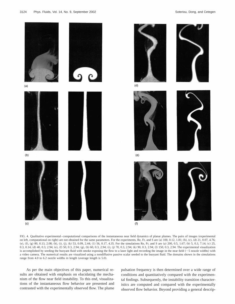
FIG. 4. Qualitative experimental–computational comparisons of the instantaneous near field dynamics of planar plumes. The pairs of images~experimentalon left, computational on right! are not obtained for the same parameters. For the experiments, Re, Fr, and S are~a! 100, 0.12, 1.81;~b!, ~c!, ~d! 21, 0.07, 4.76;~e!, ~f!, ~g! 80, 0.13, 2.08;~h!, ~i!, ~j!, ~k! 53, 0.09, 2.44;~1! 56, 0.17, 4.35. For the simulations Re, Fr, and S are~a! 200, 0.5, 1.67;~b! 5, 0.3, 7.14;~c! 25,0.3, 0.14;~d! 40, 0.3, 2.94;~e!, ~f! 50, 0.3, 2.94;~g!, ~h! 60, 0.3, 2.94;~i!, ~j! 70, 0.3, 2.94;~k! 90, 0.3, 2.94;~l! 150, 0.3, 2.94. The experimental visualizatiois accomplished by seeding the buoyant fluid with smoke exposing the flow to a laser light and recording the image in the near field~;5 nozzle widths! witha video camera. The numerical results are visualized using a nondiffusive passive scalar seeded to the buoyant fluid. The domains shown in theonsrange from 4.0 to 6.2 nozzle widths in length~average length is 5.0!.
reh
a-am
ofen-ter-allyrip-
As per the main objectives of this paper, numericalsults are obtained with emphasis on elucidating the mecnism of the flow near field instability. To this end, visualiztions of the instantaneous flow behavior are presentedcontrasted with the experimentally observed flow. The plu
-a-
nde
pulsation frequency is then determined over a wide rangeconditions and quantitatively compared with the experimtal findings. Subsequently, the instability transition characistics are computed and compared with the experimentobserved flow behavior. Beyond providing a general desc

3125Phys. Fluids, Vol. 14, No. 9, September 2002 Lagrangian simulation of unsteady near field dynamics
FIG. 4. ~Continued.!
l/ics
esric
heseam-am-e de-
ofousof
tion of the features of the instability, the numericaexperimental comparisons also help validate the numermodel. Finally, the nature of the instability is scrutinized uing both numerical results and theoretical arguments.
B. Flow features
The unsteady flow of the near field of planar plumexhibits a variety of behaviors ranging from the symmet
al-
~about the nozzle midplane! shedding of a pair of line vorti-ces to what appears to be asymmetric vortex shedding. Tdifferent behaviors manifest themselves as the flow pareters change but may also coexist for a fixed set of pareters. The latter suggests that, to some degree, they arpendent on the flow history and on the presenceperturbations. Figure 4 presents a series of instantanecomputational and experimental visualizations of some

Thoalouo
ichimeainthr
ndpuo
d.g.dewin
inisoill toagem-
not
—oker as
tedoftly,iumon-is,
-woit arethe
e-
tedys
s,di-
hisw.ini-to
ex-n
e
tialheeldfield
nnson
onfar-eldthe
erehethe
isR
Fig
3126 Phys. Fluids, Vol. 14, No. 9, September 2002 Soteriou, Dong, and Cetegen
the most characteristic of these near field behaviors.computational and experimental data in these comparisare not obtained for the same physical cases. Realisticone would not expect to obtain one-to-one instantanecomparisons due to the noted dependence of the flowexternal perturbations and/or the flow history, both of whcannot be matched precisely between experiment and slation. Moreover, as will be shown in Sec. III D, most of thbehaviors shown in Fig. 4 are, in fact, transitional andsuch, they exhibit an enhanced sensitivity to the governphysical parameters. This acts to further complicateexperimental–computational comparisons. Thus, Fig. 4 pvides aqualitative comparison between the numerical aexperimental findings and aims to reinforce that the comtational model is capable of capturing the instantaneous flbehavior even when the latter becomes very complicateis also important to note that the images presented in Fiwere specially selected to represent our cumulative unstanding of the instantaneous flow behavior, obtained bynessing a large number of visualizations of the computatioresults.
FIG. 5. Far field instability of buoyant plumes. The flow visualizationaccomplished in a similar fashion to that of Fig. 4. The parameters are55, Fr50.3, S57.14, and are the same as those of the flow shown in4~b!. The size of the domain used in Fig. 4~b! is shown by the white dashedline.
ensly,sn
u-
sgeo-
-wIt4r-t-al
The experimental visualization of the flow presentedthe left image of each of the pairs of images of Fig. 4accomplished by seeding the buoyant fluid with mineralsmoke, exposing the flow to a laser sheet shining normathe largest dimension of the nozzle and recording the imnormal to the smallest nozzle dimension using a video caera. It is important to note that such a visualization doesyield the region in which buoyant fluid~e.g., He! exists.Unlike helium, the smoke does not constitute a continuumthe smoke/gas mixture is very dilute. As a result, the smdoes not experience mass diffusion in the same mannethe helium; rather, the evolution of the smoke field is relato the motion of small smoke particles the trajectorieswhich are dominated by convective motion. Consequenthe smoke field should be much less diffused than the helfield and should resemble the distribution of a passive, ndiffusive scalar convected by the flow. To account for ththe computational results of Fig. 4~right image in each pairof images! present the distributions of such a scalar.
Figure 4~a! displays the start-up problem. Upon initiation of the flow, a mushroom structure characterized by tcounter-rotating vortices forms and rises, leaving behindthin stem of smoked filled material. When conditions asuch that pulsation is to be manifested, the presence ofinitial mushroom is usually enough to perturb the flow byond transition~see later discussion on mechanism!. Other-wise, the flow laminarizes into a steady behavior as indicain Fig. 4~b!. Transition due to the start-up mushroom alwaleads to symmetric vortex shedding, at least in the early~intime! stages of the instability development. At later timeasymmetric behavior may prevail depending on flow contions.
With regard to Fig. 4~b! it is important to clarify thatwhile steady conditions prevail in the nozzle near field, tis not necessarily true of the downstream, far field floRather, the latter experiences an unstable behavior whichtiates with lateral, wavelike oscillations and degeneratesdisorganized unsteady motion further downstream. Anample of the initiation of this far field instability is shown iFig. 5 which displays results of a simulation with the samparameters as those of Fig. 4~b! but with a much larger com-putational domain. This far field behavior bears substansimilarities to that witnessed experimentally in Ref. 5. Tnumerical results indicate that the frequency of the far fioscillations is not the same as that observed in the nearfor the pulsating instability. Specifically, for the case showin Fig. 5 the estimated frequency of the far field oscillatio~established by visually estimating the period of oscillatifor a few cycles of the instability! is about five times lowerthan that of the near field instability. Moreover, no oscillatiis witnessed in the nozzle near field, suggesting that thisfield instability is distinctly different from the one under investigation here. It does appear, however, that the far fiinstability is a strong source for perturbations that excitenear field instability.
Figures 4~b!–4~d! describe the initiation of transitionfrom the steady, laminar condition. The numerical data wobtained by incrementally raising the Reynolds number. Texperimental data present the temporal development of
e.

s.yowlsa-nd
-
i-
lsesnd
d aous
ingistic
-asorasw
en
3127Phys. Fluids, Vol. 14, No. 9, September 2002 Lagrangian simulation of unsteady near field dynamics
FIG. 6. The frequency~f ! of pulsation of planar plumes~in terms of theStrouhal number St5 f w/Vp! as a function of the modified Richardson number. Experimental–computational comparison for the nozzle-with-wall cCorrelation based on the experimental results which were obtained fvariety of nozzle widths. Computational results for the nozzle-w/o-wall calso presented. Arrow labeled with Re indicates computational casessame Ri* ~3! but different Re~40 for bottom and 80 for top points!. Arrowlabeled withGex indicates cases with same flow parameters but differcirculation of exit vortices~1 for top point, 2 for bottom!.
transition @time increasing from~b! to ~d!#. These resultsindicate that this path to transition~i.e., from steady nonpul-satile to pulsatile! is always asymmetric at its early stageUpon further development of the instability the flow maalter its behavior to symmetric shedding depending on flconditions. Despite the asymmetry, the frequency of pution computed in the vicinity of the nozzle does correspoto that of the pulsating instability~for details of frequencydetermination see Sec. III C!. This fact, and the obvious difference in scale, distinguish the behavior in Fig. 4~d! fromthat in Fig. 5 to which it bears substantial qualitative simlarities.
Images~e!–~l! of Fig. 4 display a sample of the typicapulsating behaviors encountered in the flow near field. Ca~e! and ~l! represent the extremes of the asymmetric asymmetric behavior, respectively, while cases~f!–~k! displayintermediate behaviors. The experimental results implieloose relationship between the density ratio and the variflow behaviors. Specifically, pure helium plumes~i.e., highS! were found to be more prone to the symmetric sheddbehavior while asymmetric shedding was more character
e.a
eith
t
lds the
FIG. 7. Determination of the plume pulsation frequency for the nozzle-with-wall case with Re560 and Ri* 52 (Fr50.6,S54). The streamwise velocity isobtained as a function of time~left! at different points along the plume centerline, as indicated. Fast Fourier transform of the velocity signal yiefrequency~right!.
3128 Phys. Fluids, Vol. 14, No. 9, September 2002 Soteriou, Dong, and Cetegen
FIG. 8. Signal analysis leading to the pulsation frequency for nozzle-with-wall cases with same Ri* ~2! but different Re~60 top, 80 bottom!. The figure iscreated in a similar fashion to Fig. 7.
hiapflodtr
ntsc
hDbymioed
keea—-rgpa
heze
eed
othm
isn
theic.s ofsta-ts.Forceetry
en-nedtheerd in
ander
ter-cir-
-
l isbe-ch-atetaltaly is
of low S plumes. It is important to stress, however, that trelationship between density ratio and flow behaviorpeared tenuous/incomplete. In some instances, variousbehaviors could coexist at a fixed set of experimental contions, e.g., bifurcation between symmetric and asymmeshedding at constant S, Re, and Fr.
The computational results supported the experimefindings but also suggested a more complicated physicalnario that allows the behaviors shown in cases~e!–~l! to bewitnessed under a variety of values of Re, Fr, and S. Tscenario, the details of which will be presented in Sec. IIIlends further credibility to the rather inexact fashionwhich the images for the experimental–computational coparisons of Fig. 4 were selected. In effect, if these behavcan be achieved via many sets of parameters, the set usFig. 4 should not be particularly important.
Focussing on the features of the images in Fig. 4 maclear that even when the instability is symmetric very nthe nozzle, asymmetry prevails further downstreamconsider, for example, case~l! where symmetric vortex shedding is witnessed close to the nozzle but asymmetric lascale structures are seen further downstream. Closer instion of the flow behavior indicates that this, in fact, isgeneral scenario. That is, even in cases where vortex sding appears to initiate asymmetrically, closer to the nozthe instability exhibits symmetric features. This can be sefor example, in the experimental image of Fig. 4~g! wherethe plume appears to buldge symmetrically at about ontwo nozzle widths from the exit but the downstream shding is asymmetric. Our experience with a large numbersuch visualizations indicates that, if conditions are suchvortex formation occurs very close to the nozzle, then a symetric vortex pair is likely to form; further downstream thpair may lose its symmetry. On the other hand, if conditio
s-wi-ic
ale-
is,
-rs
in
sr
eec-
d-len,
to-f
at-
s
are such that vortex formation occurs further away fromnozzle, the vortex pair formed is likely to be asymmetrThus the symmetric and asymmetric shedding behaviorplanar plumes do not represent two distinct modes of inbility like the sinus and varicose modes of inertial jeRather they are manifestations of the same instability.this reason, in the proximity of the nozzle they experienthe same frequency for the same parameters. The asymmdevelops in space~downstream! and is a feature of the flowinternal dynamics.
C. Frequency of pulsation
Figure 6 displays a comparison between the experimtally observed plume pulsation frequency and that obtaifrom the simulations. The experimental results are forcase of a nozzle with wall while the numerical results covboth flow geometries, as indicated. Results are presenteterms of Strouhal number based on the nozzle widthvelocity (St5 f w/Vp) versus a modified Richardson numbRi* 5Ri/S. In similarity to circular plumes1 this form ofscaling provides the best fit for the experimental data. Inestingly, however, experiments also show that planar andcular plumes do not obey the same St– Ri* correlation; theexponent of Ri* for the circular case being 0.380 as compared to the 0.457 of the planar case shown in Fig. 6.
Figure 6 makes evident that the computational modecapable of capturing the experimentally observed trendtween the plume pulsation frequency and the modified Riardson number. Furthermore, the numerical results indicno significant change in the frequency when the horizonwall is removed. This is in agreement with the experimendata presented in Ref. 2. In the simulations, the frequencdetermined by obtaining the streamwise velocity~i.e., veloc-

-a
ucfoch
a
reexle
he
onth. Aabion
o
of-
ionon
n-erela-
aresesehatol-ded-
h-the
dyt oftheugh
-esForis
t, infor
is
tiosen-res.
. 6
et isverusen-am-t.
ith-
he
ninpe
3129Phys. Fluids, Vol. 14, No. 9, September 2002 Lagrangian simulation of unsteady near field dynamics
ity parallel to gravity vector! as a function of time at a particular point in the nozzle near field and then performingfast Fourier transform~FFT! of this signal. Typical resultsfrom the frequency analysis are shown in Fig. 7. To redthe possibility of error, a number of points were selectedsampling the velocity field. In Fig. 7 we show three supoints all along the nozzle centerline~edge of nozzle mid-plane! but at increasing distances from the nozzle. Suchapproach to determining the plume pulsation frequencyvery similar to that followed in the experiment. The figudistinctly shows that a dominant frequency of pulsationists in the nozzle near field. Further away from the nozzwhere the flow becomes more complex, additional higfrequencies are also present.
The frequency analysis described above requires lduration simulations, so that enough wavelengths ofdominant mode are captured to yield an accurate resultexplained in Sec. II C this can be achieved at a reasoncomputational cost by implementing exit boundary conditB. The circulation of the exit vortices was selected asGex
51. The lack of dependence of the computed frequency
FIG. 9. Strouhal versus Froude number plot of the data of Fig. 6 pertaito the nozzle-with-wall case. The correlation shown is based on the exmental results.
FIG. 10. Buoyant velocity based Strouhal number StR5 f w/Agw versus theFroude number for the data of Fig. 9.
er
nis
-,r
gesle
n
this value ofGex was proven via comparisons with resultssimulations in whichGex52. One such comparison is included in Fig. 6.
As shown in previous experimental studies, the pulsatfrequency of buoyant plumes does not depend stronglythe Reynolds number.1,3 The results presented herein are cosistent with this observation. This is apparent in Fig. 6 whthe fluid viscosity does not appear in the frequency corretion. It is reinforced in the same figure for the Ri* 53 casewhere simulations at two different Reynolds numberspresented. In addition, details of the signal analysis for cawith Ri* 52 and different Re are provided in Fig. 8. Threlative unimportance of the Reynolds number implies tthe mechanism of the instability is essentially inviscid. Flowing a similar argument as above, it can also be concluthat the mass diffusivity~or, equivalently, the Schmidt number! does not affect the frequency of pulsation.
Closer inspection of the Strouhal versus modified Ricardson number expression of Fig. 6 can be revealing as todominant physics driving the instability. This has alreabeen alluded in the previous paragraph where the impacdiffusion was discussed. Here, we further recognize thatexponent of the modified Richardson number is close enoto 0.5 so that we can approximate
St5c Ri* 0.457' c Ri* 0.55 cG~S!
Fr, ~12!
whereG(S)5A121/S andc and c are constants. The function G(S) varies very weakly due to limitations on the valuof the density ratio and the presence of the square root.helium–air mixtures at STP the maximum density ratioSmax'7. At the other extreme, i.e., asS tends to unity, buoy-ancy effects diminish and the pulsation may cease. In facprevious experimental work it has been suggested thatS,1.667 ~i.e., 1/S.0.6! the pulsating instability is notexperienced.1,6 While our numerical results indicate that thlow Scriterion is not comprehensive~in the simulations pul-sating plumes were experienced at even lower density rabut at Fr and Re numbers not easily achievable experimtally! it does exemplify the point that pulsating plumes atypically witnessed in a rather limited range of density ratioThe above described limiting conditions yield 0.63,G(S),0.92. The experimental and computational data of Figare in an even narrower range, i.e., 0.82,G(S),0.92. Ne-glecting the weak variation ofG(S), Eq. ~12! can be ap-proximated as St' c/Fr where c is another constant. Thevalidity of this expression is verified in Fig. 9 where thStrouhal number is plotted versus the Froude number. Iworth noting that the dominance of the Froude number othe density ratio in the frequency correlation is a fortuitoeffect that can be useful in the quantification of the frequcies of pulsating buoyant flames and fires where an unbiguous definition of the Richardson number is not eviden3
Closer inspection of Eq.~12! reveals that further simpli-fications are possible if the Strouhal number is scaled wthe buoyant velocity scaleAgw, rather than the nozzle velocity, i.e., StB5 f w/Agw5StFr5 cG(S). Neglecting, as be-fore, the weak impact of the density ratio this implies that t
gri-

. The t
3130 Phys. Fluids, Vol. 14, No. 9, September 2002 Soteriou, Dong, and Cetegen
FIG. 11. Time evolution of the plume near field for the nozzle-w/o-wall case~top! and an idealized plume~bottom! which is free of nozzle–wall effects andis not pushed in the domain by a prescribed velocity—see text for details. The flow is visualized by plotting the centers of the transport elementswosimulations are for the same buoyant and viscous parameters: buoyant Reynolds number ReB5Re/Fr5rpwAgw/m5133.33, and S57.14. The use of ReB isnecessary for the free plume where no externally imposed nozzle velocity exists. The actual parameters for the nozzle-w/o-case are Re540, Fr50.3, S57.14. The time interval of the left to right evolving frames is 0.208.
lure
re
r
te
nc-
othnthi
orlin
as
freioietre
hei-ise-
oc-a
theotofser
herre
tedofis
eref anhatasyee-ithig.ithin-em-
new Strouhal number is effectively a constant. This concsion is verified in Fig. 10 where the results of Fig. 6 areplotted in terms of ReB and the Froude number. The figuindicates that the values of ReB exist in the rather narrowrange 0.33,ReB,0.5. Furthermore, it appears that for F.0.25 the range is even narrower 0.4,ReB,0.5. This dis-cussion can be summarized into the statement
f planar plume5 cG~S!Ag
w' cAg
w, ~13!
where according to Fig. 10,c is a constant of about, buslightly less than, 0.5. Assuming that the gravitational acceration is fixed, then the planar plume pulsation frequevaries mainly with the nozzle width with all other flow parameters playing a secondary role.@As noted in the Introduc-tion, a similar dependence for the frequency of pulsationthe nozzle geometry and the gravitational acceleration togiven by Eq.~13! has been documented for circular buoyaflames. For circular buoyant plumes, on the other hand,behavior is less similar; the exponent of 0.380 in the St–R*correlation is different enough from 0.5 to suggest a mcomplicated dependency of the frequency on the controlparameters.#
Besides the negligible impact of momentum and mdiffusion and the small impact of the density ratio, Eq.~13!suggests that the nozzle velocity does not affect thequency of pulsation in a significant way. Partial explanatfor this may be provided by the fact that the nozzle velocitconsidered here exist within a range, as noted in the Induction. Specifically, these velocities are neither extremlow for the flow to interact with the nozzle walls~i.e., no
-
l-y
natte
eg
s
-nso-ly
flow attachment to external walls, no recirculation into tnozzle throat! nor high enough for inertial effects to domnate. Thus, Eq.~13! is not a general statement but one thatvalid within a certain range of the values of the nozzle vlocity. Nevertheless, within this range both the nozzle velity and the presence of the horizontal wall do not playsignificant role on the pulsation frequency. It appears thatinstability is a phenomenon internal to the flow and is ndriven by inlet boundary conditions other than the widththe nozzle from which buoyant fluid ensues and, to a lesextent, by the density ratio. This argument is explored furtby employing a numerical ploy. In this, simulations weexecuted in which buoyant fluid simply rises~i.e., withoutbeing pushed at a given velocity! out of a fictitious slotwhich has no walls. In other words, two points are selecwithin the two-dimensional domain to indicate the edgesthe fictitious slot. Buoyant fluid enters the domain from thslot only because of the tendency of this fluid to rise. Whthis fluid comes from is not apparent due to the absence oactual nozzle but this does not invalidate the test. In wfollows, we define the flow arising from this arrangementa free plume to exemplify that no wall, or inlet velociteffects exist in this case. Numerical results indicate that frplumes pulsate in a similar fashion to actual plumes and wthe same pulsation frequency. This is clearly shown in F11 where the evolution of the free plume is contrasted wthe nozzle-without-wall case for about two cycles of thestability. In Fig. 11 the flow is visualized by plotting thtransport elements, in effect visualizing the Lagrangian co

moszls
freth
isatt-o
thanstsn
lts/
ontilice
anvngr
enais
de
ueth
deex-alde-
dul-ted
as-rent
-har-tileisu-re-ns-rethe
fon
lsoin
heheig.itionrce
n
hele.sterar
zzletrictheesto
rtexthehegers.
chthe
hatbedy-cu-
si-e-n-ttricri-
i
tedv
xe
3131Phys. Fluids, Vol. 14, No. 9, September 2002 Lagrangian simulation of unsteady near field dynamics
putational points. Since the transport elements are alsoterial elements such visualizations are equivalent to ththat would be obtained by seeding the flow at the nozcorners with particles that follow the fluid. The figure showthat the real plume is more prone to asymmetry than theplume but that the frequency of pulsation is essentiallysame.
D. Flow transition
As already noted, the instability under investigationexperienced under conditions where buoyancy dominover inertia. Whether or not the instability will manifest iself, however, will also depend on the relative importancethe viscous forces. When the latter dominate, the flow innozzle near field will be laminar and steady. In order to qutify the parameter range for which the instability manifeitself, in the experiment the flow was realized at differeconditions and was categorized~by visual inspection of thenozzle near field! as pulsating or nonpulsating. The resuwere plotted in a Reynolds versus inverse density ratio (1S)plot which provided the best correlation of the transitidata, i.e., in this plot the transition region between pulsaand nonpulsatile behavior was very narrow. This plot whis repeated here in Fig. 12, clearly indicates that as the dsity ratio increases~1/S decreases! the transition Reynoldsnumber decreases. In contrast, the narrowness of the trtion region suggests that the Froude number does not hasignificant impact on transition. This is a rather surprisiresult since it implies that the buoyant velocity is not impotant to transition while the nozzle velocity is.
The computational results do not support the experimtal evidence about the effect of the Froude number on trsition. Rather, they indicate an identifiable impact of thparameter, an impact which becomes more pronouncethe density ratio decreases. This disparity between expments and simulations will be elaborated upon in subseqparagraphs. At this juncture, and in order to investigate
FIG. 12. Experimental–computational comparison of plume transitionterms of the Reynolds number and the inverse density ratio (1/S). Largesymbols denote the computation results and the lines the trends suggesthem. The experimental results are for a variety of nozzle widths andlocities leading to a variable Fr. The computational results are for a fiFr50.3.
a-ee
ee
es
fe-
t
ehn-
si-e a
-
-n-
asri-nte
features of transition, numerical results at a fixed Frounumber (Fr50.3) are considered and contrasted to theperimental findings of Fig. 12. In the simulations numericnoise acts as the source of perturbations that lead to thestabilization of the flow. A similar approach to that followein the experiments in determining whether the flow was psatile or not, was used. That is, simulations were execufor long enough times so that the near field flow wassumed to have reached a stationary state. Three diffedensity ratios were investigatedS57.14, 2.94 and 1.67~1/S50.14, 0.34, and 0.6!. For each density ratio, simulations at increasing Reynolds numbers were carried out cacterizing the plume behavior from the steady, nonpulsato the pulsatile states. Characteristic instantaneous flow valizations from the computational transition study are psented in Fig. 13. The visualizations are in terms of the traport elements. The two middle columns in this figurepresent the types of behaviors which we associate withlimits of nonpulsatile~second column from left! and pulsatile~third column! behavior. Figure 13 identifies the impact othe viscous and buoyant forces on both the transition andthe post-transitional dynamics of this flow. As a result, it ahelps explain the instantaneous flow behavior witnessedFig. 4. The variation of the viscous force in Fig. 13 is via tReynolds number while that of the buoyant force via tdensity ratio. Comparison of the three rows of images of F13 makes clear that as the buoyancy increases, transoccurs at a lower Reynolds number. When the viscous fodominates, on the other hand, the flow is steady~first col-umn!. As this force is diminished the flow transitions to aunsteady behavior~second column!. This transition is asym-metric for all density ratio cases, at least away from tnozzle where the instability has grown enough to be visibFurther increases in the Reynolds number promote fagrowth of the instability which, as a result, exhibits nonlinefeatures~vortical structures! within the domain of visualiza-tion. These structures tend to be asymmetric about the nocenterline and appear to be an outgrowth of the asymmebehavior experienced at lower Reynolds numbers. AsReynolds number is further increased, the flow becommore complicated and the formation of the vortices tendsoccur ever closer to the nozzle. As this happens, the voformation starts to increasingly favor the symmetric overasymmetric behavior. It is important to point out that tfrequency of pulsation in the nozzle vicinity does not chanas the shift from asymmetric to symmetric shedding occuThis is consistent with the results of the Sec. III C whiindicated that the pulsation frequency is not dependent onReynolds number. Thus, the results of Fig. 13 indicate tthe asymmetric vortex shedding of planar plumes canconsidered as an intermediate behavior in the transitionnamics of these flows. This conclusion motivated the partilar selection of computational images shown in Fig. 4.
It is important to note that in the experiment, the trantion from asymmetric to symmetric behavior was not exprienced for all density ratio cases. Specifically, for low desity ratio ~weak buoyancy!, the symmetric behavior was nowitnessed and the flow consistently favored the asymmevortex shedding. This, however, is an artifact of the expe
n
bye-d

lements.
3132 Phys. Fluids, Vol. 14, No. 9, September 2002 Soteriou, Dong, and Cetegen
FIG. 13. Stages of transition for planar plumes with Fr50.3 but different density ratiosS57.15 (1/S50.14), top,S50.2.94 (1/S50.34), middle, andS51.67 (1/S50.6), bottom. The Reynolds numbers are indicated. Each frame in the figure is constructed by plotting the centers of the transport e
paitiotaapuathr iob
wt
ulhheimndi
nonnte
heeri-ionnsi-ol-
ereterit-
s.itfores
n-herare
l-slywe
that
mental setup which imposes limitations on the choice oframeters, as discussed earlier. In particular, the transstudies were executed by starting from a nonpulsatile sand incrementally raising the nozzle velocity. Such anproach increases simultaneously the Reynolds and Fronumbers; in fact, for a given transition run, one is a linefunction of the other. Thus, conditions such as those ofbottom right image in Fig. 13, where the Reynolds numbehigh but the Froude number is low to moderate, were prably not encountered in the experiments.
The limitations on the experimentally achievable flostates noted above, are also probably responsible foraforementioned disparity between experiments and simtions on the impact of the Froude number on transition. Tlinear relationship between the Re and Fr coupled with otrestrictions on the values of the dimensional parametersply that in the experiment the regions of high Re-low Fr alow Re-high Fr are not comprehensively sampled. This wtend to make the transition region appear narrower thaactually is. For example, at low density ratio, transitiwould require low Fr~to increase the already weak buoyaforce! and high Re, that is, a set of conditions not adequarepresented in the experimental data.
-nte-deres-
hea-er-
llit
tly
The ability to independently vary Re, Fr, and S in tsimulations avoids the problems encountered in the expments noted above. To effectively explore the flow transitbehavior, however, a more rigorous and reproducible tration criterion is also necessary. This is outlined in what flows: For each set of buoyancy conditions~Fr and S! simu-lations at incrementally higher Reynolds numbers wexecuted, starting with low enough values of this parameso that the nonpulsatile behavior of the flow may be wnessed. The flow is computed without exit~boundary condi-tion A! until the plume rises to a height of 10 nozzle widthThe flow field up to the first five nozzle widths from the exis inspected for unsteady effects. Specifically, we searchdisturbances along the material lines. If the material linappear perfectly smooth~e.g., like the Re55, 1/S50.14, Fr50.3 case in Fig. 13! then the flow is characterized as nopulsatile and another simulation is performed at a higReynolds number. When clearly noticeable perturbationsobserved along the material lines~similar to those of thesecond column of Fig. 13! then the flow is declared as pusatile. Evidently, this pulsatile state is not as unambiguoudefined as the nonpulsatile one. To reduce this ambiguity,define a noticeable disturbance to be the maximum one

ucigth
orth
lst
igi
mreevt tr
p-
athtivr.iathcaeeRn
elu
tivth
indoline
heey-
twogestition
edncyber.a-
isAszlethe
n-a
wsn.
en-ver-an-
ifi-a
ndis
este
intralso
ich-ob-
therror
3133Phys. Fluids, Vol. 14, No. 9, September 2002 Lagrangian simulation of unsteady near field dynamics
can be experienced without the formation of rotational strtures such as the ones found in the two left columns of F13. The transition Reynolds number is determined to beaverage of the highest Re nonpulsatile case and the csponding lowest Re pulsatile case. In order to illustrateambiguities inherent in this approach, in the presentationresults, the Reynolds numbers of the pulsatile and nonputile behavior noted above are used to define error bars ontransition Reynolds number.
Results from this transition study are presented in F14 in a Re versus 1/S plot. The transition region shownFig. 12 for the Fr50.3 case is also repeated here to exeplify the fact that the current criterion for transition is mostrict than the one used in that figure. Figure 14 makesdent that the Froude number impacts transition, allowing ioccur at lower Reynolds numbers as the Froude numbereduced~at fixed S!. The impact of the Froude number apears to be more significant at lower density ratios~higher1/S!. As noted earlier, this is in the range of conditions ththe experimental data set may be incomplete. The factthe Froude number should impact transition makes intuisense since the buoyant force depends on both S and Faccount for this, the data of Fig. 14 are replotted in Fig. 15terms of the Richardson number, the parameter whichproximately incorporates the effects of both S and Fr onbuoyant force. A high degree of correlation of the numeridata is observed yielding a transition relationship betwthe Reynolds and Richardson numbers of the form'c0 Ri20.627 wherec0 is a constant which should depend othe nature and relative abundance of perturbations and ontransition criterion. Currently, it is not totally obvious to thauthors why the Ri exponent should take the particular vaof 20.627. A simple scaling argument based on the relastrengths of the buoyant and viscous forces revealsGrashof number as the sole parameter controlltransition—indeed, linear stability analyses of this flowindicate the Grashof number as the parameter controltransition.26 In this flow, an inlet Grashof number can bdefined as
FIG. 14. Impact of Froude number on transition in a Reynolds versusverse density plot. Computational results are obtained according to thesition criterion defined in the text. The transition region of Fig. 12 is ashown for reference.
-.e
re-eofa-he
.n-
i-ois
tateTo
np-elne
the
eee
g
g
Gr5g~S21!w3
n2 5Re2 Ri, ~14!
implying a transition relationship between Re and Ri of tform Re5c0 Ri20.5. This relationship is similar enough to thone determined numerically, to effectively support the buoant versus viscous forces argument for transition. Therelationships are also different enough, however, to sugthat other physical processes also play a role in the transof planar plumes.
Finally, the transition correlation of Fig. 15 can be usto further explain the witnessed diminished dependeof the experimental transition results on the Froude numSubstituting the definition of Ri in the transition correltion yields Re5c0(S21)20.627Fr1.254. This reveals that fora given density ratio, the transition Reynolds numberclose to being a linear function of the Froude number.already noted, however, at a given density ratio and nozwidth, the experimental results are also obtained underconstraints of a linear Re–Fr relationship@this becomesapparent when one considers the identity Re5~Re/Fr!Fr5(r`g1/2/m)(w3/2/S)Fr]. These facts imply that for fixed Sonly a very narrow range of nozzle widths will lead to trasition to the pulsating instability, i.e., the widths that defineslope of the linear Re–Fr experimental relation that allofor an intersection with the almost linear transition relatioAs a result, the transition Re–Fr curve is not comprehsively sampled in the experimental set and leads to the oall underestimation of the impact of Froude number on trsition.
E. Nature of instability
Armed with the above numerical–experimental quantcation of the flow behavior, we now attempt to developmore in-depth understanding of the flow destabilization adevelopment. Results have indicated that the instabilityessentially inviscid in origin and that in its developed stagit leads to the formation of vortical structures that domina
-n-FIG. 15. Planar plume transition as a function of the Reynolds and Rardson numbers. The figure displays the computational data of Fig. 14tained with the new transition criterion. The correlation shown is forsolid line power fit to the data. Dashed lines indicate power fits of the ebars shown in Fig. 14.

apth
rt
yl-in
-:arrm
larahitynha
nhetioero
des-e
iere
ncdiiagis
meoyhiacn
rnch
twa
no
on
ra-l
ity.
cts.byisis-
s
rst.ing
eng
theec-ialere
ntst isp-todphs,g ascen-
n-ial
in aarlythethe
3134 Phys. Fluids, Vol. 14, No. 9, September 2002 Soteriou, Dong, and Cetegen
the flow field. This, in turn, suggests that an analysisproach based on vorticity dynamics may be beneficial incase.
1. General vorticity dynamics
As a first step in this analysis the vorticity transpoequation is revisited. This equation@Eq. ~8!# may be rewrit-ten in a form that more clearly reveals the impact of buoancy on the vorticity field by eliminating the material acceeration using the momentum equation and by employcontinuity, i.e.,
Dv
Dt5
1
r ReF¹2v2
¹r
r3~¹3v!G1
¹r
r2 3¹ p1¹r
r2 3S
Fr2n.
~15!
Equation~15! reveals that in this flow the vorticity of a material element is modified by three physical mechanisms~i!Diffusion, which is represented by the terms in the squbrackets,~ii ! baroclinic generation, represented by the teinvolving the pressure gradient, and~iii ! buoyancy, repre-sented by the term involving the Froude number. Thetwo terms are commonly referred to as the vorticity genetion terms. This is to distinguish them from diffusion whicprimarily redistributes and dampens an existing vorticfield ~diffusion also generates vorticity through the secoterm in the brackets but this effect is small compared to tof the other generation mechanisms!. The generation termsproduce vorticity as neighboring fluid elements of differedensity experience unequal material accelerations wacted upon by a common force. These unequal acceleracoupled with continuity~i.e., no gaps may be formed in thfluid! require the material elements to engage in mutualtation. In the buoyancy case, the common force is proviby gravity while in the baroclinic case by the inertial presure gradient. Mathematically, these phenomena arepressed in the form of the cross products in Eq.~15! whichindicate that vorticity is produced when the pressure gradand gravitational acceleration vectors are misaligned withspect to the density gradient vector. For the buoyamechanism, this implies that only horizontal density graents contribute to the generation of vorticity. The vectornature of the generation terms implies that they are stronlinked to the geometry of the flowmap. The latter, in turn,heavily influenced by the vorticity generated by these terThe consequence of this coupling is the creation of thetremely complicated flow structures often witnessed in buant flows. It is important to note, however, that despite tcomplexity, the generated vorticity is constrained by the fthat the net circulation has to remain invariant. This costraint is a consequence of the fact that the only exteforce acting on the fluid is the gravitational body force whiis potential and, hence, imparts no net angular momentumthe fluid. To accommodate this constraint, each of thegeneration terms produces equal amounts of positivenegative circulation.
Given that appropriate scales have been used in thedimensionalization of the governing equations, Eq.~15!yields the relative sizes of the three vorticity modificati
-is
-
g
e
st-
dt
tnns
-d
x-
nt-y-lly
s.x--st-al
onond
n-
terms. Specifically, buoyancy/baroclinicity;O(S/Fr2) andbuoyancy/diffusion;O(Re S/Fr2). In this flow, the Froudenumbers are consistently less than unity and the densitytios are greater than unity~in our numerical and experimentaresults 0.01,Fr,1 and 1.5,S,7!. Consequently, S/Fr2
.1 suggesting dominance of buoyancy over baroclinicAlso, typical Reynolds numbers are in the range of 1,Re,1000 yielding S Re/Fr2@1 and implying a diminished im-portance of viscous effects compared to buoyancy effeThus, Eq.~15! implies that the most important mechanismwhich the vorticity of a material element is altered in thflow is that of buoyancy generation. Consequently, the dcussion of the flow vorticity dynamics which is to follow ito primarily focus on this mechanism.
2. Impact of buoyancy generation—the nonpulsatingflow
The case of the non-pulsating plume is considered fiNumerical/experimental visualizations of the nonpulsatplume have already been shown in Fig. 4~b!. A schematic ofthe flow is also shown in Fig. 16. In this, the steady plumflow is visualized by sketching the material lines originatiat the nozzle corners. We first consider the case whereregions of molecularly mixed material are thin and are efftively constrained in the vicinity of these corner materlines. In such a case, these lines bound the region whbuoyant fluid exists. In addition, the local density gradiecan be taken as approximately normal to these lines. Iimportant to clarify that the thin diffusion regions assumtion is not one that is essential to the analysis which isfollow; it simply reduces the complexity of the proposearguments. As will be discussed in subsequent paragrathick diffusion regions can also be accommodated as lonthese regions do not substantially merge at the nozzleterline.
Figure 16 clarifies that in the nozzle near field, the desity gradient vector, which is normal to the corner mater
FIG. 16. Schematic representation of vorticity generation by buoyancystable planar plume. Vorticity is generated in the thin regions of moleculmixed material bounding the plume where the density gradient andgravitational acceleration vectors are misaligned. The magnification onright shows some of the details of these regions.

e-ioothhtc
tiobio
nssuw
betathvamt
onththen
llts
ogti
thr-sft
rt
tivi-heleth
incab
anox-e
n-linea-zlesi-
ses
ioner,uc-ofe-
berial
of
e
thetionszlebehe
Then-
withine.ntsbyuidlowncetoe
3135Phys. Fluids, Vol. 14, No. 9, September 2002 Lagrangian simulation of unsteady near field dynamics
lines, is substantially misaligned to the gravitational acceration vector which is vertical~parallel to the nozzle centerline!. As explained, such a misalignment leads to productof vorticity by buoyancy. The geometrical arrangementthe vectors is such, that positive vorticity is created onleft hand side while negative vorticity is created on the righand side. This satisfies the noted constraint that the netculation has to remain constant. The generated circulawill tend to accelerate the flow upwards. This can easilyconceptualized when one considers the motion in the regbetween two regions of counter-rotating vorticity of sigsimilar to the ones described above. Mass conservationgests that the increased speed of the fluid due to the neadded circulation should lead to a narrowing of the gaptween the two corner material lines, i.e., these lines will sconverging towards the nozzle centerline as shown infigure. The misalignment of the density gradient and gratational acceleration vectors persists farther downstrehowever. As a result, more circulation is produced leadingfurther convergence of the corner material lines. This cvergence will be most dominant near the nozzle since inregion the added circulation represents a very large parthe total circulation. Further away from the nozzle, while trate of circulation production remains approximately costant~see next paragraph!, the material line convergence wibe less significant since the added circulation represensmaller proportion of the accumulated local circulation.
The fact that the rate of circulation production does nvary substantially with height for low diffusion nonpulsatinplumes can be seen by considering the Lagrangian evoluof the circulation of an elemental material segment ofthin region of molecularly mixed fluid surrounding the coner material lines—see Fig. 16. The elemental segment iareadA5d l dn whered l anddn are the length and width othe segment. To establish the circulation equation we ingrate the vorticity equation@Eq. ~15!# over the area of thesegment under the assumption that the mechanism of voity generation by buoyancy is dominant. This yields
D
Dt EdAv dA'E
dA¹3S 12
S
r D n
Fr2dA. ~16!
Note that the integrant on the right-hand side is an alternaform of the last term of Eq.~15! that arises as an intermedate step in the derivation of the vorticity equation from tmomentum equation. Also the material derivative on thecan be removed from the integral by recognizing thatarea of the Lagrangian segment is not a function of timethis incompressible case. Using the definition of vorticity aapplying the Stokes theorem, the left-hand-side integralbe shown to be equal to the circulation. Furthermore,applying the Gauss theorem to the integral on the right-hside and assuming that the material segment is apprmately vertical~i.e., its d l dimension is approximately parallel to the y axis! with its vertical sides exposed to thplume and ambient densities, Eq.~16! becomes
DG
Dt'2
~S21!
Fr2d l , ~17!
l-
nfe-ir-n
en
g-ly-
rte
i-,
o-isof
-
a
t
one
of
e-
ic-
e
ftendnydi-
i.e.,DG/Dt5c* d l wherec* is a constant. The negative sigon the right-hand side of Eq.~17! indicates that the circulation produced on the right-hand side of the nozzle centerwill be negative. A similar derivation of the circulation eqution for material segments on the left-hand side of the nozcenterline shows that the circulation production there is potive.
The earlier noted result that the plume velocity increawith height implies thatd l will also increase away from thenozzle. Consequently, the rate of production of circulatfor the segment will increase with height. This, howevdescribes the Lagrangian evolution of the circulation prodtion rate. What is of interest here is the Eulerian ratecirculation change with height. By considering the ondimensional~i.e., vertical! evolution of the circulation field,recognizing that the flow is steady~in a Eulerian sense!, andusing Eq.~17! we can write
]G
]y'c*
d l
v. ~18!
It has already been stated that asv increases so doesd l .It can be proven that their ratio is a constant. This canaccomplished by considering the kinematics of matelines, i.e.,
D~d l!
Dt5d l•¹u. ~19!
By employing the same assumptions as in the derivationEq. ~18!, Eq. ~19! can be rewritten as
v]~d l !
]y5d l
]v]y
⇒ ]~v/d l !
]y50 ~20!
which implies thatv/d l is constant withy. This result com-bined with Eq.~18! implies that away from the nozzle whermaterial line curvature is not significant
]G
]y;constant with elevation. ~21!
It should be evident from the above discussion thatessentially inviscid dynamics associated with the generaof vorticity by buoyancy should lead to infinitely thin plumerising at infinite velocities as the distance from the noztends to infinity.~It is noted that the same conclusion canobtained by considering the Bernoulli integral along tstreamline coinciding with the nozzle centerline.! In reality,this does not happen due to the presence of diffusion.latter is expected to have a significant impact on the dowstream dynamics where the diffusion regions associatedthe two corner material lines start to merge at the centerlThis merging leads to a decay of the local density gradieand to a reduction of the rate of circulation producedbuoyancy. Effectively, the absence of pure buoyant flthere leads to a weakening of the buoyant force and a sdown of the mixed material due to an increased dominaof the viscous force. Such a slow down is very proneinstability as suggested in Ref. 5. This instability, which w

the
fusthrzlisndse
tuiono
th-
itre
e-a
hetioths-e
thtter
emeoral-
esre-zlehis
cin-lyant
yedtheor-us/ingthethe
to-ner
is inboutxi-n
the
isnyoned
lcede
hel be
-n
tionono ist.
e
a-f
3136 Phys. Fluids, Vol. 14, No. 9, September 2002 Soteriou, Dong, and Cetegen
suspect to be the one leading to the destabilization offlow in Fig. 5, belongs to the group of instabilities which wtermed as being of the far field.
In the near field, on the other hand, the impact of difsion is expected to be secondary. The relative slownesdiffusion as compared to the other processes involved indevelopment of the flow~see scaling analysis given earlie!precludes the merging of the diffusion regions in the noznear field. As a result, the impact of viscous diffusionconstrained to a minor dampening of the vorticity field ato weak generation within the molecularly mixed regionMass diffusion, on the other hand, is expected to thickthese regions while, at the same time, decay the magniof the local density gradients there. These two mass-diffusrelated effects, tend to counterbalance one another whecomes to circulation production by buoyancy. Evidencethis is offered by the fact that neither the thickness ofdiffusion regions (dn) nor the magnitude of the density gradients there (]r/]n) appear in Eq.~17!. It can be clarifiedfurther by recognizing that as long as the overall densdifference is maintained across the molecularly mixedgions and these regions remain thin, then]r/]n'(S21)/dn which implies (]r/]n) dn'(S21)5constant.
Thus, the overall driving force for the buoyant flow rmains effectively unaffected by diffusion in the nozzle nefield. The impact of diffusion on the overall shape of tcorner material lines is also small. This is because the moof these lines is controlled by the convective rather thandiffusive motion of the fluid. As a result, even in the preence of significant diffusion, these lines will still convergtowards the nozzle centerline. They will no longer boundregion where buoyant fluid exists, however. In fact, the laregion can be substantially larger and it may even be dive
FIG. 17. The stable planar plume with Re53, Fr50.3,S57.14—free plumecase. The figure is a composite one displaying the transport elements~cen-ter!, together with the Lagrangian residence time, 1/uuu, of the elements ofthe middle layer~left!, and the generated circulation~right! summed on aone-dimensional equispaced mesh~positive and negative summed seprately!. Axes are nondimensional and show correct relative magnitudesall quantities but may experience a shift of origin~the generated circulationat y50 is zero and the nozzle midplane is atx51!.
e
-ofe
e
.ndenit
fe
y-
r
ne
er
g-
ing with height.~This leads to the significant disparity in thappearance of laminar plumes when visualized using soform of passive tracer, e.g., the visualizations of Fig. 4,when the region of variable density or temperature is visuized, e.g., as in Ref. 26.! Finally, it is noted that the highvelocities in the region between the corner material lincreate asymmetries in the corner material line diffusiongions making them smaller on the side facing the nozcenterline as compared to the side facing the ambient. Tguarantees that the sharper gradients will reside in the viity of the corner material lines and will be approximatenormal to these lines even when diffusion is more significthan previously speculated.
The preceding discussion on the secondary role plaby diffusion effects in the nozzle near field suggests thatanalysis of the inviscid dynamics of the mechanism of vticity generation by buoyancy should be valid in the viscodiffusive case as well. This conclusion can be tested usthe numerical results. Figure 17 presents such results forfree-plume case. The figure is a composite one displayingtransport elements~center! which describe material linesoriginating in the neighborhood of the nozzle corners,gether with the residence time of the elements of the cormaterial line ~left! and the produced circulation~right!summed on a one-dimensional equispaced mesh~positiveand negative parts summed separately!. It is noted that eventhough the Reynolds number is quite low~lowest of all simu-lations!, S Re /Fr2 is still large ~;240! and diffusion can beassumed to be less important than buoyancy. The figureagreement with the qualitative statements made earlier athe physics of this flow. Of particular interest is the appromately linear growth of circulation with height which is iagreement with Eq.~21!.
3. Flow destabilization from the steady condition
On further consideration, it becomes apparent thatmonotonically increasing ~magnitude-wise! circula-tion with height is a condition necessary for stability in thflow. When this condition is met, the velocity induced at apoint along the corner material lines from the circulatiabove that point, will be greater than the velocity inducfrom the circulation located below that point, i.e.,]G/]y' constant⇒G(y 1 dy) . G(y 2dy) ⇒ uu(y) u from G(y1dy)
.uu(y)u from G(y2dy) . The velocity induced from above wilbe directed towards the nozzle centerline while that indufrom below will be directed away from this line. Thus, thnet induced velocity vector will be directed towards tnozzle centerline and, consequently, the material lines wilmonotonically converging towards this line.
In contrast, when the condition of monotonically increasing circulation with height is violated, vortex formatiois to be anticipated. Due to the near zero values of circulaat the inlet and the dominant internal circulation productiby the buoyancy mechanism, the only alternative scenarithat of nonmonotonic increase of circulation with heighSuch a distribution implies local maxima for circulation~as-sumed symmetric about the nozzle centerline!. At points inthe vicinity of the local maxima, the velocity induced by th
or

estx-tha
uldhelei
in
va
erbeioneetot
inrnonths-mstho
ionto-
ioo
cu
clhe
si-leute-
nma.ed
-ismri-a
not
Incaltheec-uch,ated
oftricthey istionap,n-ly
visu-
bili-intheuse
hatingairun-in
n-owize
ultngu-smg ofit toent
nceilend
tioowo
rias t
3137Phys. Fluids, Vol. 14, No. 9, September 2002 Lagrangian simulation of unsteady near field dynamics
circulation field at larger heights is not necessarily largthan that from lower heights. Specifically, for points juabove the maxima the velocity induced from below will eceed that from above. In contrast, for points just belowmaxima, the velocity induced from above will exceed thfrom below by a margin that is greater than that which wobe manifested if the circulation maxima did not exist. Timplication of all this is that, when compared to the stabflow case, the material lines above/below the maximum wappear to be rotating away/towards the nozzle centerlThis is schematically shown in Fig. 18. This accelerates~ver-tically! the flow below the maxima and decelerates it abothem, thus allowing the further accumulation of circulationthe region of the local maxima. More importantly, howevthe local rotation of the material lines is such that theycome more vertical. As a result, the production of circulatby buoyancy intensifies in this region as the angle betwthe density gradient and gravitational acceleration vectends to ninety degrees. This accelerates the destabilizaprocess by intensifying the local circulation maxima andducing the local flow to rotate around these maxima. In tuthis results in vortex formation and the further intensificatiof the local circulation maximum as each vortex entrainscirculation in its immediate vicinity. It is noted that the preence of local maxima in the circulation field is a phenoenon that can lead to destabilization in all vortex flowBuoyant plumes, however, are much more susceptible tomechanism due to the enlargement of the maxima by buancy as explained above. Finally, it is noted that diffustends to counterbalance the above phenomena and leadstabilization of the flow. The impact of diffusion is particularly important at the early stages of the destabilizatmechanism when, depending on the local convective, buant and diffusive timescales, the local maxima in the cirlation field may be eliminated~smoothened out! by diffusionor grow as described above. Thus, unlike the earlier consion that the impact of diffusion on the mechanism of t
FIG. 18. Schematic representation of the impact of a pair of circulamaxima in the vicinity of the nozzle. The diagram on the left shows the flin terms of the corner material lines while that on the right the variationmagnitude of the circulation with elevation for either of the corner matelines. The horizontal dashed line connecting the two diagrams indicatelocation of the circulation maxima.
r
et
lle.
et,-
nrsion-,
e
-.isy-
the
ny--
u-
instability is negligible, the effect of this process on trantion will be dominant, i.e., diffusion plays an important roin determining whether the flow is stable or unstable, bonce the instability is manifested the impact of diffusion bcomes secondary.
Intrinsic to the mechanism of the flow destabilizatiodescribed above is the presence of the circulation maxiThe origin of the initial pair of such maxima must be tracto the time dependence of boundary conditions~i.e., the pres-ence of perturbations! and/or the initial condition. Subsequent pairs are induced by the first pair via a mechanwhich is to be described in the following paragraph. Expementally, perturbations that lead to the initial pair of maximmay be induced by the ambient atmosphere which maybe perfectly at rest, by the experimental setup~oscillations inflow-rate, nozzle vibration, sound waves in buoyant fluid! orby the downstream, far-field flow which is rarely steady.the simulations, perturbations are provided by numerinoise, the downstream flow or, in the cases with exit, byexit boundary condition. All these perturbations are not nessarily symmetric about the nozzle centerline and, as smay lead to unsteady phenomena that are more complicthan those described above. The symmetric introductionthe buoyant fluid at the nozzle and the related symmegeneration of vorticity by buoyancy there, tend to enforcesymmetric behavior at subsequent times. Such symmetrlost downstream, however, because the internal generamechanisms, dependent as they are on the local flowmtend to amplify small differences on either side of the ceterline. Thus, far from the nozzle, the flow develops highasymmetric features as witnessed in the instantaneousalizations of Fig. 4.
4. Description of repetitive shedding once first vortexpair forms
Having described the basic mechanism for the destazation of this flow, we now embark on an effort to explathe phenomenon of periodic shedding of vortices inplume near field. To address this issue we, again, makeof kinematical arguments. For simplicity we first assume ta pair of counter-rotating vortices is in the process of beformed from an externally imposed perturbation. The ptends to rise as each vortex induces a velocity on its coterpart. As each vortex matures, it will increasingly entrathe circulation produced in its immediate vicinity by straiing the corner material lines there. Focusing on the flbetween the vortex pair and the nozzle exit, we recognthat the entrainment of circulation by the vortices will resin a reduced rate of increase of circulation with height alothe corner material lines in this region. That is, while circlation is still being produced by the buoyancy mechaniand tends to accumulate as material lines age, the straininthese lines removes some of this circulation and entrainsthe vortex core. The strain field, and hence the entrainmrate, induced by the vortex, however, decays with distafrom the vortex core. This decay is faster than linear whthe rate of increase of circulation by accumulation will teto be linear with distance as noted earlier~i.e., assuming that
n
flhe

3138 Phys. Fluids, Vol. 14, No. 9, September 2002 Soteriou, Dong, and Cetegen
FIG. 19. Details of the time evolution of approximately one cycle of the near field instability for a free planar plume with Re540, Fr50.3,S57.14. Sequenceof frames from left to right and top to bottom with time interval 0.08. Each frame is created in a similar fashion to Fig. 17.
tiaadalbehewie
ugandniound
ivoon
oubceec
ven in
heinne
charntsthet ofismAssi-ain
thear-
y
e
for the flow behind the vortex pair, which bears substangeometrical similarities to the steady plume, quasisteconditions exist!. This leads to a scenario where locmaxima for the circulation are created at some distancehind the vortex pair. Effectively, as the vortices rise and thdistance from the nozzle increases, a time will be reacwhen the weakly strained material lines near the nozzleacquire a circulation that is larger than the strongly strainmaterial lines above them. Alternatively stated, even thothe material lines in the nozzle vicinity are younger ththose immediately above and, hence, are characterizelower magnitudes of vorticity, they are also less strained aas a result, they end up with larger amounts of circulatdue to their larger area. Once the scenario of larger amoof circulation located under smaller amounts is manifestethe nozzle vicinity, a new vortex pair forms as describedearlier paragraphs. Thus, according to this discussion, atex pair in the nozzle near field coupled with the introductiof more buoyant material by the nozzle and the dynamicsvorticity generation by buoyancy, will tend to generate a ssequent vortex pair. This leads to the shedding of vortiand the pulsating nature of the near field of buoyant plumIt is important to recognize the significance of the introdu
ly
e-irdlldh
byd,nts
innr-
f-ss.-
tion of new buoyant material by the nozzle in the abomechanism. This constrains the presence of the pulsatiothe vicinity of the nozzle.
Evidence for the validity of the arguments describing tmechanism of pulsation of buoyant plumes is providedFig. 19. The figure presents details of approximately ocycle of the evolution of the instability for free plumes. Eaframe in the multiframe figure is constructed in a similfashion to Fig. 17. It is noted that the transport elemedescribe the corner material lines and the evolution ofregion occupied by them can be revealing as to the impacthe strain field. The figure makes clear that the mechanfor the pulsation of the plume described earlier is valid.the old vortex pair distances itself from the nozzle, the redence time in the nozzle vicinity increases and the strdecreases there~thicker material line region!—frame ~a!.This leads to the accumulation of circulation there andformation of the local maxima. These maxima start appeing in frame ~b! and are clearly visible by frame~c!. Oncethe local maxima form, the material lines in their vicinitstart tending towards the vertical—frame~d!. At this pointthe accumulation of circulation accelerates~compare firstand second row of frames! due to the enhanced impact of th

en
yth
ftef.thuchtesuiogtth
b
r,b
heanero
ly
to-
thajozthvi
te
yththroo
hen
ingb
veth
iocncavity, td-
ithanec-es
tion.a-re
t-atewn-ower
nss ofdel
andous
iona
Std
.e.,sreeur-ow
etryomthein
endthew-te
rnal
cyith
icestric
ofan-ifi-ch-
theudei-us
3139Phys. Fluids, Vol. 14, No. 9, September 2002 Lagrangian simulation of unsteady near field dynamics
buoyancy generation mechanism and of the entrainmVortex shedding is witnessed@from frames~d! to ~f!# both bythe physical appearance of vortices and the sharp decathe residence time between the circulation maxima andnozzle. After this point, the vortex pair matures and just aframe ~h! the pulsation cycle completes and repeats itsel
In earlier parts of this discussion, it was shown thatflow pulsates at a characteristic and repeatable Strouhal nber for each set of buoyancy conditions, i.e., for each Riardson number. The kinematical description for the vorshedding mechanism given above, helps explain why thiso. First, the mechanism is essentially inviscid and, thexcludes the viscosity as a controlling parameter. In additall quantities that play a role in this mechanism, i.e., strenand distance of the old vortex pair from the nozzle andrate of production of circulation near the nozzle,depend pre-dominately on the mechanism of vorticity generationbuoyancy. As such, they will be proportional to S/Fr2 @seeEq. ~15!# and, hence, to the Richardson number. Moreoveis recognized that the mechanism of vorticity generationbuoyancy is internal to the flow and is controlled from tboundary via the density difference between the buoyantambient fluids and the size of the nozzle—the latter defithe location of the incoming corner material lines and pvides a length scale to the problem. The nozzle velocity~and,hence, the inlet shear!, on the other hand, does not strongimpact this mechanism. This enables the elimination ofVp
from the St;Ri correlation noted in Sec. III C, and leadsEq. ~13! for the pulsation frequency. Similarly, other modifications to the inlet boundary conditions, such aspresence/absence of a horizontal wall at the nozzle exit,not expected to impact the pulsation frequency in a maway. In fact, other than the density difference and the nozwidth, the only other external parameter that can affectmechanism of vorticity generation by buoyancy is the gratational acceleration, which under most circumstancesconstant.
The arguments in the previous paragraph are consiswith the discussion in Sec. III C and with Eq.~13!. It is worthpointing out, however, that the rather simple dependencthe frequency on external flow parameters prescribed byequation, does not imply that the physics leading toshedding/pulsation is simple. In fact, the mechanism pposed in this section which involves the generation of a vtex and its interaction with the fluid emanating from tnozzle, suggests that quite the contrary is true. Consequeit is unlikely that this physics can be reproduced ussimple, reduced-order theoretical models. It may actuallythe case that the simplest model that is able to quantitatireproduce the frequency of pulsation is that provided byfull governing equations.
Finally, a few qualitative statements on the classificatof the instability as absolute or convective. While it is aknowledged that an unambiguous classification could obe achieved via a linear stability analysis, the kinematiexplanation of the near field pulsation outlined in the preous paragraphs does tend to suggest that the instabiliabsolute, rather than convective in nature. As was seeninstability is an oscillatory one which provides its own fee
t.
ofer
em--xiss,n,he
y
ity
nds-
erer
lee-is
nt
ofise-
r-
tly,
elye
n-lyl
-is
he
back through the interaction of the downstream vortex wthe newly introduced buoyant fluid at the nozzle. Other ththe initiation perturbation, no subsequent perturbation is nessary to sustain the instability, that is, the instability donot convect downstream in the absence of such perturbaThus the instability is not an amplifier of external perturbtions~convective instability! but, rather, an internal oscillato~absolute instability!—for definitions see Ref. 22. On thother hand, the far field instability of plumes~i.e., then oneshown in Fig. 5! is convective in nature. This can be winessed by the fact that the instability does not propagupstream to reach the nozzle but, rather, convects dostream. Linear stability analyses based on the parallel flassumption are likely to focus on this latter instability raththan the near field one.
IV. SUMMARY AND CONCLUSIONS
Results of Lagrangian, Transport Element simulatiowere used to investigate the near field unsteady dynamicplanar buoyant plumes. The developed computational mowas validated via comparisons with experimental datawas shown capable of capturing the detailed instantaneflow dynamics and of reproducing the frequency of pulsatcharacteristic of this flow. This frequency, which obeysStouhal-Richardson number correlation of the form50.536 Ri* 0.457 was shown to be predominately controlleby the nozzle width and the gravitational acceleration, if ' cAg/w where c is a constant of about, but slightly lesthan, 0.5. The frequency of pulsation was the same for fstanding nozzles and nozzles with a horizontal wall srounding the nozzle exit. The instantaneous large scale flstructure displayed a strong tendency towards asymmabout the nozzle centerline, particularly as the distance frthe nozzle exit increased. This tendency was attributed totwo main mechanisms of internal generation of vorticitythe flow ~buoyancy and baroclinicity! which are strongly de-pendent on the geometrical features of the flowmap and tto amplify small differences manifested on either side ofcenterline. Irrespective of the downstream behavior, hoever, the instability was always symmetric in the immediavicinity of the nozzle~1 to 2 nozzle widths! and exhibited thesame nondimensional frequency for the same set of extebuoyancy parameters~Fr and S!. The symmetric/asymmetricbehavior was linked to the relative strength of the buoyanover the other processes governing the fluid motion. Wincreasing dominance of buoyancy the large scale vortappear closer to the nozzle, and a shift from the asymmeto the symmetric behavior is manifested.
Numerical results indicated that the relative strengthbuoyant and viscous forces plays a dominant role in the trsition from the nonpulsatile to the pulsatile behavior. Speccally, a transition relation between the Reynolds and Riardson numbers of the form Re'c0 Ri20.627 wherec0 is aconstant, was manifested. The experimental results, onother hand, suggested a negligible impact of the Fronumber on transition. This difference was attributed to limtations in the experiments arising from the simultaneo

u
thncaoo
t aelaca
ionr-cona
in
binncththu
byly
avids
lity
on-,
o
y-
f a
n
os
y-s-
a
us-,
ity
ol
edys.
ann
ndthe
in
f
fn
A
,
m-
g
lly
ine
e,’’
lf-
nu-
nut.
of
.
for
t.
3140 Phys. Fluids, Vol. 14, No. 9, September 2002 Soteriou, Dong, and Cetegen
variation of the Reynolds and Froude numbers that occwhen the nozzle velocity or width are altered.
A vorticity dynamics based analysis revealed thatinstability is inviscid in nature and arises due to the preseof the mechanism of vorticity generation by buoyancy. It wshown that in the stable, nonpulsatile flow, the magnitudethe circulation produced by this mechanism on either sidethe nozzle centerline increases monotonically with heigha rate that is approximately constant. Depending on the rtive strength of diffusion and buoyancy, destabilization moccur through external perturbations that create lomaxima in the otherwise monotonically increasing variatof circulation with height. These maxima evolve into a votex pair which self-convects away from the nozzle. Onsuch a vortex pair forms it precipitates a subsequentthrough a rather complex mechanism that enforces thepearance of new circulation maxima in the immediate vicity of the nozzle. The creation of these local maxima isconsequence of the continuous production of circulationbuoyancy just above the nozzle, coupled with the straineffect of the downstream vortex pair. The lack of dependeof the pulsation frequency on external flow parameters othan the nozzle width, the gravitational acceleration anddensity ratio is a consequence of the fact that the root caof the instability is the mechanism of vorticity generationbuoyancy which is internal to the flow and is affected mainvia the three quantities noted above.
1B. M. Cetegen and K. D. Kasper, ‘‘Experiments on the oscillatory behior of buoyant plumes of helium and helium–air mixtures,’’ Phys. Flu8, 2974~1996!.
2B. M. Cetegen, Y. Dong, and M. C. Soteriou, ‘‘Experiments on stabiand oscillatory behavior of planar buoyant plumes,’’ Phys. Fluids10, 1658~1998!.
3A. Hamins, J. C. Yang, and I. Kashiwagi, ‘‘An experimental investigatiof the pulsation frequency of flames,’’Twenty-Fourth Symposium (International) on Combustion~The Combustion Institute, Pittsburgh, PA1992!, p. 1695.
4E. E. Zukoski, inProperties of Fire Plumes, Combustion FundamentalsFires, edited by G. Cox~Academic, New York, 1995!, p. 101.
5S. Kimura and A. Bejan, ‘‘Mechanism for transition to turbulence in buoant plume flow,’’ Int. J. Heat Mass Transf.26, 1515~1983!.
6D. M. Kyle and K. R. Sreenivasan, ‘‘The instability and breakdown oround variable density jet,’’ J. Fluid Mech.249, 619 ~1993!.
7T. J. Maxworthy, ‘‘The flickering candle: Transition to a global oscillatioin a thermal plume,’’ J. Fluid Mech.390, 297 ~1999!.
8B. M. Cetegen and Y. Dong, ‘‘Experiments on the instability modesbuoyant diffusion flames and effects of ambient atmosphere on the inbilities,’’ Exp. Fluids 28, 546 ~2000!.
9E. E. Zukoski, B. M. Cetegen, and T. Kubota, ‘‘Visible structure of buoant diffusion flames,’’Twentieth Symposium (International) on Combution ~The Combustion Institute, Pittsburgh, PA, 1984!, p. 361.
10L. D. Chen, J. P. Seaba, W. M. Roquemore, and L. P. Goss, ‘‘Buoy
rs
ee
sfft
a-yl
eep--ayge
erese
-
f
fta-
nt
diffusion flames,’’Twenty Second Symposium (International) on Combtion, The Combustion Institute~The Combustion Institute, Pittsburgh, PA1988!, p. 361.
11B. M. Cetegen and T. A. Ahmed, ‘‘Experiments on the periodic instabilof buoyant plumes and pool fires,’’ Combust. Flame93, 157 ~1993!.
12M. A. Delichatsios, ‘‘Gravitational fluctuations in pool fires and pobuoyant flows,’’ Combust. Sci. Technol.112, 353 ~1996!.
13B. M. Cetegen, ‘‘Behavior of naturally unstable and periodically forcaxisymmetric buoyant plumes of helium and helium–air mixtures,’’ PhFluids 9, 3742~1997!.
14J. L. Ellzey and E. S. Oran, ‘‘Effects of heat release and gravity onunsteady diffusion flame,’’Twenty Third (International) Symposium oCombustion~The Combustion Institute, Pittsburgh, PA, 1990!, p. 1635.
15R. W. Davis, E. F. Moore, W. F. Roquemore, L. D. Chen, V. Vilimpoc, aL. P. Goss, ‘‘Preliminary results of a numerical–experimental study ofdynamic structure of a buoyant jet diffusion flame,’’ Combust. Flame83,263 ~1991!.
16V. R. Katta and W. M. Roquemore, ‘‘Role of inner and outer structurestransitional jet diffusion flame,’’ Combust. Flame92, 274 ~1993!.
17A. F. Ghoniem, I. Lakkis, and M. C. Soteriou, ‘‘Numerical simulation othe dynamics of large fire plumes and the phenomenon of puffing,’’TwentySixth (International) Symposium on Combustion~The Combustion Insti-tute, Pittsburgh, PA, 1996!, p. 1531.
18W. E. Mell, K. B. McGrattan, and H. R. Baum, ‘‘Numerical simulation ocombustion in fire plumes,’’Twenty Sixth (International) Symposium oCombustion~The Combustion Institute, Pittsburgh, PA, 1996!, p. 1523.
19J. Buckmaster and N. Peters, ‘‘The infinite candle and its stability—paradigm for flickering diffusion flames,’’Twenty First (International)Symposium on Combustion~The Combustion Institute, Pittsburgh, PA1986!, p. 1829.
20C. M. Coats, ‘‘Coherent structures in combustion,’’ Prog. Energy Cobust. Sci.22, 427 ~1996!.
21T. Yuan, D. Durox, and E. Villermaux, ‘‘An analogue study for flickerinflames,’’ Exp. Fluids17, 337 ~1994!.
22P. Huerre and P. A. Monkewitz, ‘‘Local and global instabilities in spatiadeveloping flows,’’ Annu. Rev. Fluid Mech.22, 473 ~1990!.
23S. L. Lee and H. W. Emmons, ‘‘A study of natural convection above a lfire,’’ J. Fluid Mech.11, 353 ~1961!.
24N. E. Kostovinos, ‘‘Plane turbulent buoyant jets—Turbulence structurJ. Fluid Mech.81, 45 ~1977!.
25R. Sangras, Z. Dai, and G. M. Faeth, ‘‘Mixing structure of plane sepreserving buoyant turbulent plumes,’’ ASME J. Heat Transfer120, 1033~1988!.
26L. Pera and B. Gebhart, ‘‘On the stability of laminar plumes: Somemerical solutions and experiments,’’ Int. J. Heat Mass Transf.14, 975~1971!.
27A. Krishnan and A. F. Ghoniem, ‘‘Simulation of rollup and mixing iRayleigh–Taylor flow using the transport element method,’’ J. CompPhys.99, 1 ~1992!.
28J. C. Anderson, D. M. Hum, B. G. Neal, and J. H. Whitelaw,Data andFormulae, 3rd ed.~Pergamon, New York, 1983!.
29O. M. Knio and A. F. Ghoniem, ‘‘Three dimensional vortex simulationrollup and entrainment in a shear layer,’’ J. Comput. Phys.97, 172~1991!.
30A. J. Chorin, ‘‘Numerical study of slightly viscous flow,’’ J. Fluid Mech57, 785 ~1973!.
31O. H. Hald and V. M. Del-Prete, ‘‘Convergence of vortex methodsEuler’s equations,’’ Math. Comput.32, 791 ~1978!.
32A. Leonard, ‘‘Review: Vortex methods for flow simulation,’’ J. CompuPhys.37, 289 ~1980!.