LabVIEW Programming Libraries lnees.buffalo.edu/training/FlexTest/793_LV.pdf · LabVIEW Programming...
42
l LabVIEW Programming Libraries Model 793.00 Software
Transcript of LabVIEW Programming Libraries lnees.buffalo.edu/training/FlexTest/793_LV.pdf · LabVIEW Programming...
lLabVIEW Programming Libraries
Model 793.00 Software

Proprietary data This manual, and the software it describes, are both copyrighted, with all rights reserved. Under the copyright laws, neither this manual nor the software may be copied, in whole or part, without written consent of MTS Systems Corporation, except in the normal use of the software or to make a backup copy of the software. The same proprietary and copyright notices must be affixed to any permitted copies as are made for others, whether or not sold, but all of the material purchased (with all backup copies) may be sold, given, or loaned to another person. Under the law, copying includes translating into another language or format. This software may be used on any computer, but extra copies cannot be made for that purpose.
Copyright information © 2000 - 2003 MTS Systems Corporation. All rights reserved.
Trademark information MTS, RPC, Temposonics, and TestWare are registered trademarks of MTS Systems Corporation.
FlexTest, MPT, Profile Editor, Station Builder, Station Manager, and TestStar are trademarks of MTS Systems Corporation.
LabVIEW is a trademark of the National Instruments Corporation.
Adobe is a registered trademark of Adobe Systems Incorporated. Acrobat is a trademark of Adobe Systems Incorporated.
Microsoft and Windows NT are registered trademarks of the Microsoft Corporation.
Publication information Software Version Document No. Release Date
2.4B 015-200-002 February 1999
3.0 015-200-002 B June 2000
3.1 — September 2000
3.2 — June 2001
3.3 — November 2002
3.4 — September 2003

LabVIEW Programming Libraries 3
Contents
Preface 5
Conventions 6Technical Support 9
Chapter 1 Developing Applications 13
Accessing the 793.00 VI Drivers 14Standard Connector for the Driver VI 15Wiring with Clusters 17Initializing the Controller 18Dimensions and Unit Values 19Using Driver Overview.vi for an Online Overview 21
Chapter 2 Programming Examples 23
Reading the Pod Keys 24Using the Pod Keys 25Creating a Ramp Command 26Controlling a Ramp with the Pod Keys 27Creating a Cyclic Command 28Using Data Acquisition 29Using Timed Data Collection 30Accessing the Station Configuration 31

LabVIEW Programming Libraries4
Chapter 3 Quick Reference to Driver VIs 33
LabVIEW VI Quick Reference 34
Index 41

LabVIEW Programming Libraries 5
Preface
Safety first! Before you attempt to use your MTS equipment in your test system, read and understand the Safety manual. Like an automobile, your test system is very useful—but if misused, it is capable of deadly force. You should not be afraid of your test system, but you should always maintain a healthy respect for it.
Improper installation, operation, or maintenance of MTS equipment in your test system can result in hazardous conditions that can cause severe personal injury or death, and damage to your equipment and specimen. Again, read and understand the Safety manual before you continue. It is very important that you remain aware of hazards that apply to your test system.
Other MTS manuals In addition to this manual, you may receive additional MTS manuals in paper or electronic form.
If you have purchased a test system, it may include an MTS System Documentation CD. This CD contains an electronic copy of all of the MTS manuals that pertain to your test system, including controller manuals, hydraulic and mechanical component manuals, assembly drawings and parts lists, and operation and preventive maintenance manuals.
Contents Conventions 6
Technical Support 9

LabVIEW Programming Libraries6
Conventions
The following paragraphs describe some of the conventions that are used in your MTS manuals.
Hazard conventions As necessary, hazard notices are embedded in this manual. These notices contain safety information that is specific to the task to be performed. Hazard notices immediately precede the step or procedure that may lead to an associated hazard. Read all hazard notices carefully and follow the directions that are given. Three different levels of hazard notices may appear in your manuals. Following are examples of all three levels.
Note For general safety information, see the Safety manual included with your system.
Danger notices Danger notices indicate the presence of a hazard which will cause severe personal injury, death, or substantial property damage if the danger is ignored. For example:
High intensity light and dangerous radiation are emitted by class 3B lasers.
Viewing a class 3b laser directly or viewing it using optical instruments will
cause immediate and severe injury.
Avoid eye or skin exposure to the laser beam. Ensure that all power to the laser is off before attempting any maintenance, service, or adjustment procedure.
������

LabVIEW Programming Libraries 7
Warning notices Warning notices indicate the presence of a hazard which can cause severe personal injury, death, or substantial property damage if the warning is ignored. For example:
Hazardous fumes can accumulate in the test chamber.
Breathing hazardous fumes can cause nausea, fainting, or death.
Ensure the chamber is properly ventilated before you open the chamber door or put your head or hands into the chamber. To do this, ensure the temperature controller is off and allow sufficient time for the ventilation system to completely exchange the atmosphere within the chamber.
Caution notices Caution notices indicate the presence of a hazard which will or can cause minor personal injury, cause minor equipment damage, or endanger test integrity if the caution is ignored. For example:
This specimen can develop sharp edges as a result of testing.
Handling the specimen with unprotected hands can result in cuts and
slivers.
Always wear protective gloves when you handle the specimen.
Other conventions Other conventions used in your manuals are described below:
Notes Notes provide additional information about operating your system or highlight easily overlooked items. For example:
Note Resources that are put back on the hardware lists show up at the end of the list.
Special terms The first occurrence of special terms is shown in italics.
Illustrations Illustrations appear in this manual to clarify text. It is important for you to be aware that these illustrations are examples only and do not necessarily represent your actual system configuration, test application, or software.
�������
�����

LabVIEW Programming Libraries8
Electronic manualconventions
This manual is available as an electronic document in the Portable Document File (PDF) format. It can be viewed on any computer that has Adobe Acrobat Reader installed.
Hypertext links The electronic document has many hypertext links displayed in a blue font. All blue words in the body text, along with all contents entries and index page numbers are hypertext links. When you click a hypertext link, the application jumps to the corresponding topic.

LabVIEW Programming Libraries 9
Technical Support
Start with yourmanuals
The manuals supplied by MTS provide most of the information you will need to use and maintain your equipment. If your equipment includes MTS software, look for README files that contain additional product information.
If you cannot find answers to your technical questions from these sources, you can use the internet, telephone, or fax to contact MTS for assistance. You can also fill out the Problem Submittal Form that is available on the MTS web site and in the back of many MTS manuals that are distributed in paper form.
Technical supportnumbers
MTS provides a full range of support services after your system is installed. If you have any questions about a system or product, contact MTS in one of the following ways.
MTS web sitewww.mts.com
The MTS web site gives you access to our technical support staff by means of a Problem Submittal Form and a Technical Support link.
• Problem Submittal Form: www.mts.com > Contact MTS > Problem Submittal Form
• Technical Support: www.mts.com > Contact MTS > Technical Support
E-mail: [email protected]
Telephone HELPLine 800-328-2255Weekdays 7:00 A.M. to 6:00 P.M.,Central Time
Fax 952-937-4515Please include an MTS contact name if possible.
Before youcontact MTS
MTS can help you more efficiently if you have the following information available when you contact us for support.
Know your site numberand system number
The site number contains your company number and identifies your equipment type (material testing, simulation, and so forth). The number is usually written on a label on your MTS equipment before the system leaves MTS. If you do not have or do not know your MTS site number, contact your MTS sales engineer.
Example site number: 571167
When you have more than one MTS system, the system number identifies which system you are calling about. You can find your job number in the papers sent to you when you ordered your system.
Example system number: US1.42460
Know information fromprior technical
assistance
If you have contacted MTS about this problem before, we can recall your file. You will need to tell us the:
• MTS notification number

LabVIEW Programming Libraries10
• Name of the person who helped you
Identify the problem Describe the problem you are experiencing and know the answers to the following questions.
• How long has the problem been occurring?
• Can you reproduce the problem?
• Were any hardware or software changes made to the system before the problem started?
• What are the model and serial numbers of the suspect equipment?
Know relevant computerinformation
If you are experiencing a computer problem, have the following information available.
• Manufacturer’s name and model number
• Operating software type and service patch information. Examples:
– Windows XP Service Pack 1 (SP1)
– Windows 2000 Service Pack 3 (SP3)
– Windows NT 4.0 Service Pack 7 (SP7)
• Amount of system memory. Example: 640 MB of RAM.
• Amount of free space on the hard drive in which the application resides. Example: 11.2 GB free space, or 72% free space.
• Current status of hard-drive fragmentation. Example: 3% total fragmentation.
LabVIEW Programming Libraries 11
Know relevant softwareinformation
For MTS software application problems, have the following information available.
Station Manager, Version 3.3A, Build 1190, Patch 4
• Names of other non-MTS applications that are running on your computer, such as screen savers, keyboard enhancers, print spoolers, and so forth
If you contact MTSby phone
Your call will be registered by a HELPLine agent if you are calling within the United States or Canada. Before connecting you with a technical support specialist, your agent will ask you for your site number, name, company, company address, and the phone number where you can normally be reached.
Identify system type To assist your HELPLine agent with connecting you to the most qualified technical support specialist available, identify your system as one of the following types:
• Electromechanical materials test system
• Hydromechanical materials test system
• Vehicles test system
• Vehicles component test system
• Aero test system
Be prepared totroubleshoot
Prepare yourself for troubleshooting while on the phone.
• Call from a telephone close to the system so that you can try implementing suggestions made over the phone.
• Have the original operating and application software media available.
• If you are not familiar with all aspects of the equipment operation, have an experienced user nearby to assist you.
Write down relevantinformation
Prepare yourself in case we need to call you back.
• Remember to ask for the notification number.
• Record the name of the person who helped you.
• Write down any specific instructions to be followed, such as data recording or performance monitoring.
After you call MTS logs and tracks all calls to ensure that you receive assistance and that action is taken regarding your problem or request. If you have questions about the status of your problem or have additional information to report, please contact MTS again.
Problem SubmittalForm in MTS manuals
In addition to the Problem Submittal Form on the MTS web site, there is also a paper version of this form (postage paid) in the back of many MTS manuals. Use this form to communicate problems you are experiencing with your MTS software, hardware, manuals, or service. This form includes check boxes that allow you to indicate the urgency of our problem and your expectation of an acceptable response time. We guarantee a timely response—your feedback is important to us.

LabVIEW Programming Libraries12

LabVIEW Programming Libraries 13
Chapter 1
Developing Applications
This chapter describes how to use the 793.00 System Software driver virtual instruments (VIs). It begins with a description of how you can configure the LabVIEW environment to access the driver VIs. The rest of the chapter discusses various programming issues, such as initializing your controller and using system units.
Contents Accessing the 793.00 VI Drivers 14
Standard Connector for the Driver VI 15
Wiring with Clusters 17
Initializing the Controller 18
Dimensions and Unit Values 19
Using Driver Overview.vi for an Online Overview 21

LabVIEW Programming Libraries14
Accessing the 793.00 VI Drivers
We recommend that you add the MTS 793.00 VI drivers to your LabVIEW “Controls” and “Functions” palettes. This makes it very convenient to add 793.00 items to your front panels and wiring diagrams. The LabVIEW drivers have been organized on your disk so they can be conveniently added to your palettes. Refer to Chapter 8, “Customizing Your LabVIEW Environment,” in the LabVIEW User Manual for instructions explaining how to do this.
You can directly insert submenus that are linked to a directory in both your controls and functions palettes. When selecting the directory to link, choose the “...\LabVIEW\MTS 793 Drivers” directory under your installation directory.
For example, if you installed FlexTest IIm in the default location, c:\ftiim, you would locate “c:\ftiim\LabVIEW\MTS 793 Drivers” for the above step. The “Select a directory” dialog box will display subfolders such as “Hydraulics” and “Function Generation” when you’ve located the correct spot.
You can also copy or move the driver set to user.lib in your LabVIEW directory. If you copy the “...\LabVIEW\MTS 793 Drivers” folder and all its subfolders into user.lib, you will find the 793.00 controls under the “User Controls” icon on the Controls palette and the 793.00 VIs under the “User Libraries” icon on the Functions palette. A benefit of copying the MTS 793.00 VI drivers into user.lib is that LabVIEW will automatically search there for subVIs when loading a VI. This allows you to place your applications anywhere on your disk and have LabVIEW automatically find the driver VIs.
Another option for accessing the drivers is to load Driver Overview.vi, open its wiring diagram, and drag the VIs from there to your application as you need them.

LabVIEW Programming Libraries 15
Standard Connector for the Driver VI
The following figure shows the standard connector for the Model 793.00 driver VI.
Connectorterminals
All VIs use the same pattern, but not all use all defined inputs and outputs.
• The upper left and upper right corners are usually Handle In and Handle Out.
• The lower left and lower right corners are always Error In and Error Out.
Each value is passed to the Model 793.00 VI as either a single value or as part of a cluster. If a cluster is the required input, the Index parameter determines the processed elements. The Index value is represented by a LabVIEW enumerated type. Each cluster has an associated index enumeration for specifying the fields of the cluster. Every enumeration has “All Fields” available as the first value. “All Fields” causes all parameters to be processed. Any other Index value identifies the single parameter from the cluster that is processed.
Station Handle In For VIs that require a station, this input is the handle that was returned by Station
Open.vi. The station handle indicates the station on which the application wants the operation performed.
Handle In For VIs that operate on data acquisition or function generator “objects,” this is the handle that was returned when the object was originally created. For example, FG
State.vi accepts a handle to a function generator (allocated by FG Open.vi) on this input terminal. For other VIs, this input indicates the item to be used or queried by the VI. For example, Mode Info.vi accepts the name of a control channel on this input terminal.
Input Value or Cluster This is the data input to the controller. Any data that is to be sent to a controller must be wired into this input. If the VI supports only a single parameter, this input will be a single value. If the VI supports multiple parameters, the input will be a
Handle In Handle Out
Value or Cluster Value or Cluster
Index
Error OutError In
Set
Station Handle In
LabVIEW Programming Libraries16
cluster containing all supported parameters. A single call to a VI with multiple parameters can operate on any single parameter or on all parameters. This is determined by the Index input. If the Set parameter requests a Read only, it is not necessary to wire this terminal.
Set Determines how the VI operates on the input parameters. Choices are:
• Get Value—Read the current value of the required parameter(s) from the controller
• Set Value—Write, then read the new value of the requested parameter(s) to and from the controller
Error In The standard LabVIEW error cluster, as described in LabVIEW documentation. In the Model 793.00 driver VIs, if an error exists when the VI is called, no processing occurs and the error condition is passed directly to Error Out.
Index A code specifying the processed parameters. If Index is set to “All Fields,” all parameters in the input cluster are processed. If Index is any other value, only the parameter indicated is processed.
Handle Out Same as Handle In (passed through). Handle Out is used primarily to control data flow in a wiring diagram.
Output Value or Cluster Contains current values as returned from the Controller for each parameter that has been processed by the call. If Index is “All Fields,” all parameters are updated. If Index is any other value, only the specified parameter is updated, while all other cluster parameters remain unchanged.
Error Out The standard LabVIEW error cluster, as described in LabVIEW documentation. If an error condition exists when the VI is called, no processing occurs and the error code (reported in Error In) passes through to Error Out. Any errors that occur during processing are reported in Error Out. If an error occurs inside a VI, the Error Out cluster will have its status field set to ERROR, its code field set to a Model 793.00 Software error code, and its source field set to a string message describing the error.
Because of the way Model 793.00 Software reports errors internally, the error codes in the code field are not always the same when the same error occurs. The string message in the source field will always contain an accurate explanation of the error.
Viewing a Sample VI To view a VI that uses most of the standard terminals, open Driver Overview.vi. Display the wiring diagram, then turn on LabVIEW help (on the PC, Ctrl-H), and place the cursor over the icon labeled “Pod Btns.” This displays the wiring pattern for the VI. Notice that some wires are required, others are recommended, and still others are optional.

LabVIEW Programming Libraries 17
Wiring with Clusters
Most driver VIs include Input and Output clusters with the same data structure. All elements in all clusters have been named to allow the use of the Bundle and Unbundle By Name functions. When a cluster is wired into the input side of Unbundle, the names are immediately available for selection in the output field.
The Bundle By Name function has three terminals (from left to right). This is often a source of confusion. The middle terminal must be wired with a cluster pattern or template. There are three ways to wire this terminal when using driver VIs:
1. The first is to open the front panel of the driver VI and drag the input cluster to the front panel of the VI you’re creating. A cluster terminal will also appear on the wiring diagram which can be wired to the middle terminal of the Bundle By Name function. The names will then be available for selection in the input field (left-hand part of the Bundle function).
2. The second way can be used if there has been a previous call to the driver VI, either to get values or to set values. Because the structure of the input and output clusters is the same, the output of one VI call can be used as a pattern for the input to the next call to the same VI. The following example illustrates both. Note that none of the driver VIs are completely wired.
Note that in both cases, the only elements of the cluster that are changed by the Bundle by Name function are those that are specifically wired. All other elements pass through unchanged. Also note that the VI will process only the element(s) specified by the index input. Index zero calls for all elements to be processed.
3. The third way is to insert the cluster onto the front panel using the Controls palette. Each unique cluster is stored in a separate LabVIEW custom control (*.ctl). If you are using the default LabVIEW palette, choose “Select a Control...” and use the dialog box to find the cluster you need. Or, if you’ve customized your palette for the drivers (which we recommend), use the Model 793.00 submenu icon to find the cluster you need.

LabVIEW Programming Libraries18
Initializing the Controller
Before running anything in the LabVIEW environment, you must establish communication with a test station. This is accomplished by calling Station
Open.vi. When your test is complete, call Station Close.vi to close the connection to the controller and release system resources. If you stop an application without calling Station Close.vi, Station Open.vi will fail the next time the application tries to open the same station. It will usually report the error message: “The application has attempted to open the same station more than once.” The only known workaround is to close LabVIEW, thus forcing all connections to stations to be closed.

LabVIEW Programming Libraries 19
Dimensions and Unit Values
Controller firmware does all of its calculations based on engineering units, not voltage. The engineering units used are referred to as system units and are defined in the sysdef.udf file.
SYSDEF.UDF is distributed with the system and is not intended to be
changed by anyone.
Serious problems can result if this file is changed inappropriately. Just changing the assignments in SYSDEF.UDF will not appropriately change what the system does internally!
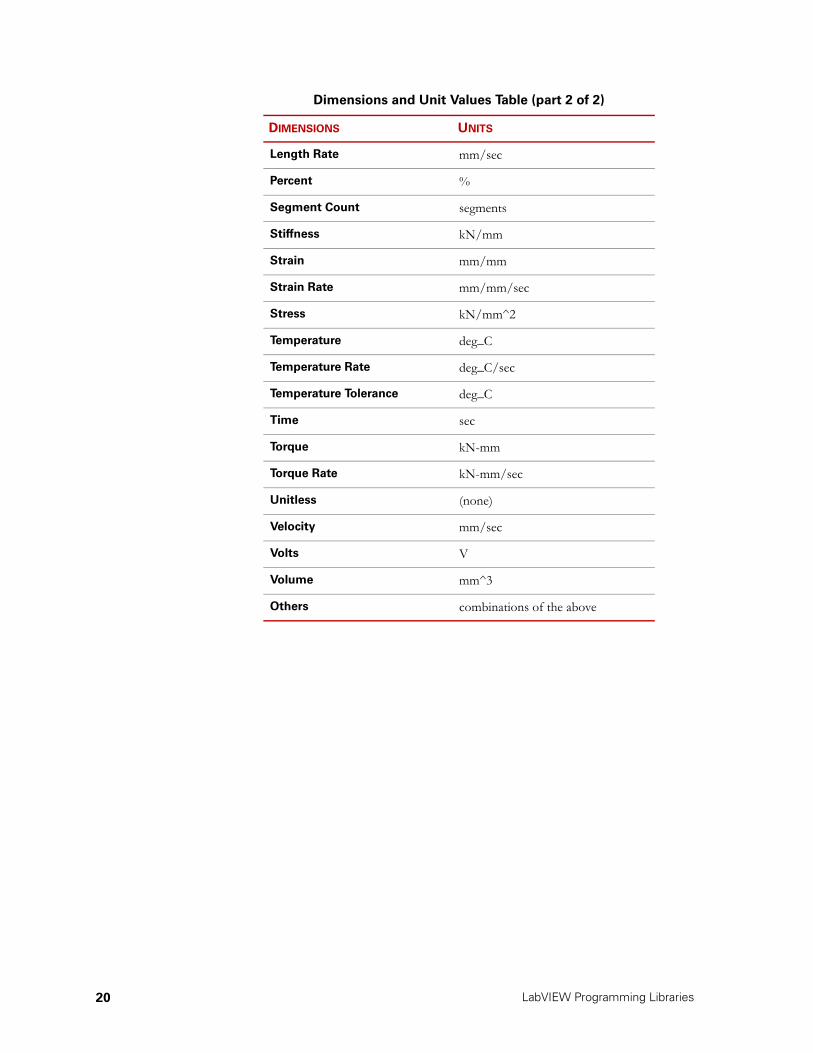
The system units are defined by their dimension (for example, length or force) and SI metric unit value (for example, mm or kN). All the values sent to and returned from the controller are returned in these units. The LabVIEW drivers always use system units.
For example, if you run data acquisition on a force channel, the data values are returned in kilonewtons (kN); if you run data acquisition on a strain channel, the data values will be returned in millimeter-per-millimeter (mm/mm).
A list of the system units is shown below.
Note You must communicate with the digital controller in terms of the units contained in the following table.
.Dimensions and Unit Values Table (part 1 of 2)
DIMENSIONS UNITS
Acceleration mm/sec^2
Angle deg
Angle Rate deg/sec
Area mm^2
Compliance mm^2/kN
Damping kN-sec/mm
Energy kN-mm
EPV (Energy Per Volume) kN-mm/mm^3
Force kN
Force Rate kN/sec
Frequency Hz
Length mm
CAUTION
LabVIEW Programming Libraries20
Length Rate mm/sec
Percent %
Segment Count segments
Stiffness kN/mm
Strain mm/mm
Strain Rate mm/mm/sec
Stress kN/mm^2
Temperature deg_C
Temperature Rate deg_C/sec
Temperature Tolerance deg_C
Time sec
Torque kN-mm
Torque Rate kN-mm/sec
Unitless (none)
Velocity mm/sec
Volts V
Volume mm^3
Others combinations of the above
Dimensions and Unit Values Table (part 2 of 2)
DIMENSIONS UNITS

LabVIEW Programming Libraries 21
Using Driver Overview.vi for an Online Overview
The Driver Overview.vi application is useful reference to the driver VI set. Open the Driver Overview.vi wiring diagram to see all of the driver icons arranged in functional groups as shown in the following figure.

LabVIEW Programming Libraries22

LabVIEW Programming Libraries 23
Chapter 2
Programming Examples
This chapter describes the example programs installed with the programming libraries. These programs demonstrate various tasks typically associated with materials testing. The example programs illustrate the use of the LabVIEW driver set to control Model 793.00 test systems.
Finding the exampleprograms
The example programs are installed in the LabVIEW directory beneath the main Model 793.00 installation directory, typically c:\ftiim\labview or c:\tsiis\labview.
Using the LabVIEWexamples
The LabVIEW example programs can be loaded and executed immediately. Load an example by finding its main VI file (*.VI) and opening it from the LabVIEW environment. You can also double-click on the .VI file from the Windows NT Explorer.
Contents Reading the Pod Keys 24
Using the Pod Keys 25
Creating a Ramp Command 26
Controlling a Ramp with the Pod Keys 27
Creating a Cyclic Command 28
Using Data Acquisition 29
Using Timed Data Collection 30
Accessing the Station Configuration 31

LabVIEW Programming Libraries24
Reading the Pod Keys
LabVIEW program PODREAD.VI
Description PODREAD examines the status of various parameters of the load unit control panel and reports it to the operator. The parameters include the hydraulic power supply (HPS) status, test control status, and hydraulic service manifold (HSM) status.

LabVIEW Programming Libraries 25
Using the Pod Keys
LabVIEW program PODKEYS.VI
Description PODKEYS exercises the load unit control panel more completely than the previous PODREAD program. You will be able to press the RUN, STOP, and HOLD keys, and the system will respond.

LabVIEW Programming Libraries26
Creating a Ramp Command
LabVIEW program RAMP.VI
Description RAMP demonstrates how you would initialize the machine controller interface, create a function generator ramp in position control, and then queue and execute that ramp. It allows you to enter a final position and a ramp time, and then starts the test when you press a key on the keyboard.
When the ramp is done, it sends a message back to the program. The main test execution loop waits for a message to come back from the controller, and then processes it. In this example program, there is only one message of interest, and that is the message that is sent when the ramp is complete. The program waits for a message by using Get Event.vi. When the “ramp done” message is received, the program is finished.

LabVIEW Programming Libraries 27
Controlling a Ramp with the Pod Keys
LabVIEW program RAMP2.VI
Description RAMP2 is similar to RAMP, except that it makes use of the Remote Station Controller's Test Control Stop, Hold, and Run/Resume keys to control the test during test execution. You begin the test by pressing the Run/Resume switch and can hold the test or terminate the test using the Hold or Stop switch, respectively.
This program is similar in structure to the RAMP program but involves more communication between the program and the system controller. Instead of only one possible message coming back from the controller, the program will now receive messages each time the Remote Station Controller's Test Control Stop, Hold, or Run/Resume switch is pressed.
The Pod.vi call tells the controller which message should be sent back to the program when a particular switch on the Remote Station Controller is pressed. The main test execution loop is modified to watch for these particular messages and handles them appropriately. For example, the test does not start until the “Run key pressed” message is received from the system. When this message is received, the function generator is started.

LabVIEW Programming Libraries28
Creating a Cyclic Command
LabVIEW program CYCLE.VI
Description CYCLE is similar to RAMP2, except that it does cyclic function generation instead of a single ramp function. The program prompts you for the minimum and maximum position endlevels, the frequency, and the initial ramp time. When you start the test, it ramps up to the minimum position, and then cycles through ten cycles. As in RAMP2, you control the test using the RSC keys.

LabVIEW Programming Libraries 29
Using Data Acquisition
LabVIEW program LINEAR.VICIRCULAR.VI
Description The LINEAR and CIRCULAR programming examples demonstrate how to set up simple data acquisition using the techniques described in this section.
Data acquisition processes will be set up to trigger on certain events and then notify a buffer object of the event. An event could be a peak/valley or a timer going off.
A buffer object will respond to an external trigger by collecting data and inserting the data into a buffer. A buffer object is defined by using DAC Config.vi to configure the buffer settings for data acquisition.
You must create a trigger to signal the buffer object. Various trigger types are available for the detection of different events:
• Time Trigger.vi
• Level Trigger.vi
• Zero Trigger.vi
• PV Trigger.vi
When the trigger starts, it will wait for an event. When the trigger sees that event, it will signal the buffer object. The buffer object will then collect data on the channels that it has been told to sample. DAC Signals.vi sets up the buffer object to collect data on channels.
An application retrieves data collected by a buffer using DAC Read.vi. This VI copies data from the internal buffer into a LabVIEW array.
When a buffer is filled with data, the message tag specified in DAC Config.vi will be sent to the application. After a buffer becomes full, and when the application is ready to discard the data in the current buffers so that they can be refilled, the application needs to call DAC Buf Empty.vi. This will reset the count variable to zero and start filling the data buffer again.
Circular buffers are filled continuously. In order to get a “snapshot” of the buffer, an application can call DAC Read.vi. This VI will fill a LabVIEW array with the oldest data in the first (0) location. Since a circular buffer is being continuously updated by the controller, the only safe time to access its data is when data acquisition is complete or the data acquisition is in a stop or hold state.

LabVIEW Programming Libraries30
Using Timed Data Collection
LabVIEW program TIMED.VI
Description TIMED collects a single buffer of data without doing any function generation. Its purpose is to monitor the position of the actuator for a few seconds, collecting 25 data points in the process.
The DAC Time Reset.vi is used to reset the clock to zero at the start of the test. When data is subsequently collected on the time data channel, the time values recorded will be with respect to the start of the test.

LabVIEW Programming Libraries 31
Accessing the Station Configuration
LabVIEW program STACONFIG.VI
Description STACONFIG retrieves information from the controller definition. The program displays information about the input signals, control channels, and control modes.
STACONFIG is an example of how you’re expected to retrieve controller information and use it in your program. By using the controller definition calls, you don’t need to rely on hard-coded settings to determine channel names for data acquisition, control, or any other calls that require channel information.

LabVIEW Programming Libraries32

LabVIEW Programming Libraries 33
Chapter 3
Quick Reference to Driver VIs
This chapter has a quick reference list that describes all the LabVIEW driver VIs. It also lists input and output wires, and cluster contents.
Contents LabVIEW VI Quick Reference 34

LabVIEW Programming Libraries34
LabVIEW VI Quick Reference
Quick Reference to LabVIEW Driver VIs (part 1 of 6)
VI DESCRIPTION INPUT WIRES OUTPUT WIRES CLUSTER CONTENTS
SYSTEM INITIALIZATION
Station
Names
Get the names of all available stations Error In
Station NamesError Out
Station Open Initialize the link to a station; empty string for station name defaults to first station on list
Station NameApplication NameApplication TypeError In
Station Handle
Error Out
Station Close Close link to station and free up all associated resources (including all function generator and data acquisition objects open on this station)
Station HandleError In Error Out
FUNCTION GENERATION
FG Open Allocate function generator handle
Station Handle
Error InFG Handle outError Out
FG Close Close function generator and free up all associated resources
FG Handle InError In Error Out
FG State Stop/hold/start function generation
FG Handle InFG State InSetError In
FG Handle OutFG State Out
Error Out
FG Segment
Counter
Set/Get channel segment count
FG Handle InSegment Count InSetError In
FG Handle OutSegment Count Out
Error Out
FG
Compensation
Set/Get type of compensation and state of compensation
FG Handle InCluster InIndexSetError In
FG Handle OutCluster Out
Error Out
Comp Type:• None• Null Pacing• APC• Peak/Valley• AIC• ALC• PVPComp State:• On/Off

LabVIEW Programming Libraries 35
FG Config Set/Get control channel and control mode for function generation
FG Handle InCluster InIndexSetError In
FG Handle OutCluster Out
Error Out
Control ChannelControl Mode
FG Cyclic Set/Get FG cyclic parameters
FG Handle InCluster InIndexSetError In
FG Handle OutCluster Out
Error Out
Wave Shape:• Sine• Triangle• Square• RelativeFrequencyEnd Level 1End Level 2CyclesDone Tag
FG Scalable
Cyclic
Set/Get FG scalable cyclic parameters (uses current output level as mean)
FG Handle InCluster InIndexSetError In
FG Handle OutCluster Out
Error Out
Wave Shape:• Sine• Triangle• SquareFrequencySpanCyclesDone Tag
FG Adjust
Mean
Set/Get the mean of a scalable cyclic waveform (only valid when FG is running)
FG Handle InScalable Mean InSetError In
FG Handle OutScalable Mean Out
Error Out
FG Monotonic Set/Get FG monotonic params
FG Handle InCluster InIndexSetError In
FG Handle OutCluster Out
Error Out
Wave Shape:• Sine• Triangle• Square• RelativeRate Type:• Freq• Rate• TimeRateEnd LevelDone Tag
DATA ACQUISITION
DAC Open Open a data acquisition “object” that combines acq and buffering
Station Handle
Error InDac HandleError Out
DAC Close Close acq “object” and free all associated resources
Dac HandleError In Error Out
Quick Reference to LabVIEW Driver VIs (part 2 of 6)
VI DESCRIPTION INPUT WIRES OUTPUT WIRES CLUSTER CONTENTS

LabVIEW Programming Libraries36
DAC State Set/Get execution state of data acquisition
Dac Handle InDac State inSetError In
Dac Handle OutDac State out
Error Out
DAC Reset Resets all triggers associated with a data acq “object”
Dac Handle InError In
Dac Handle OutError Out
DAC Time
Reset
Reset controller timestamp to 0.0
Station HandleError In Error Out
DAC Config Set/Get Buffer parameters
Dac Handle InCluster InIndexSetError In
Dac Handle OutCluster Out
Error Out
Buffer TypeSizeBuf msg tag
DAC Read Copy buffered data from controller buffers to a LabVIEW array
Dac Handle InSignal nameData buffer inError In
Dac Handle OutPoints copiedData buffer outError Out
DAC Buf
Empty
Empties the buffer(s) associated with a data acq “object” so the controller can fill with new data
Dac Handle InError In
Dac Handle OutError Out
DAC Buf Fill Copy all available data from the controller into the buffers associated with a data acq “object”
Dac Handle InError In
Dac Handle OutError Out
DAC Signals Add, delete, or query for signals chosen for acquisition with a given data acq “object”
Dac Handle InSignal NameAdd/Del/QueryError In
Dac Handle OutCurrent Signal Names
Error Out
Latch Signal Get named signal from latch array. Latch all signals if flag is True, otherwise just read
Station HandleSignal nameLatch flagError In
Signal value
Error Out
Poll Signal Get an individual signal value
Station HandleSignal NameError In
Signal ValueError Out
DAC Triggers Add, delete, or query for the triggers configured for acquisition with a given data acq “object”
Dac Handle InTrigger Handle InAdd/Del/QueryTrigger TypeError In
Dac Handle OutTrigger Handle OutCurrent Trigger Handles
Error Out
Quick Reference to LabVIEW Driver VIs (part 3 of 6)
VI DESCRIPTION INPUT WIRES OUTPUT WIRES CLUSTER CONTENTS

LabVIEW Programming Libraries 37
DAC Trigger
Type
Query the type of a trigger handle
Trigger Handle In
Error In
Trigger Handle OutTrigger TypeError Out
Time Trigger Set/Get the time interval for a timed data acquisition trigger
Trigger Handle InTime Interval InSetError In
Trigger Handle OutTime Interval Out
Error Out
Level Trigger Set/Get parameters for a level crossing data acquisition trigger
Trigger Handle InCluster InIndexSetError In
Trigger Handle OutCluster Out
Error Out
Signal NameLevel Crossing Increment
Zero Trigger Set/Get parameters for a “zero crossing” data acquisition trigger
Trigger Handle InCluster InIndexSetError In
Trigger Handle OutCluster Out
Error Out
Signal NameZero LevelSensitivity
Limit Trigger Set/Get parameters for a limit crossing detector
Trigger Handle InCluster InIndexSetError In
Trigger Handle OutCluster Out
Error Out
Signal NameLimit ValueDirection:• Increasing• DecreasingLimit Crossed Tag
Running
MinMax
Trigger
Set/Get the signal to monitor for a running min/max trigger
Trigger Handle InTrigger Signal InSetError In
Trigger Handle OutTrigger Signal Out
Error Out
MinMax
Trigger Get
Min
Get the current value of the trigger signal at the latest minimum detected
Trigger Handle In
Error In
Trigger Handle OutSignal value at running minError Out
MinMax
Trigger Get
Max
Get the current value of the trigger signal at the latest maximum detected
Trigger Handle In
Error In
Trigger Handle OutSignal value at running maxError Out
PV Trigger Set/Get parameters for a peak/valley data acquisition trigger
Trigger Handle InCluster InIndexSetError In
Trigger Handle OutCluster Out
Error Out
Signal NameSensitivity
PV Change
Trigger
Set/Get parameters for a peak/valley change detector (sends a message when a change is detected)
Trigger Handle InCluster InIndexSetError In
Trigger Handle OutCluster Out
Error Out
Signal NameSensitivity:Change TolerancePeak ReferenceValley ReferenceChange Tag
Quick Reference to LabVIEW Driver VIs (part 4 of 6)
VI DESCRIPTION INPUT WIRES OUTPUT WIRES CLUSTER CONTENTS

LabVIEW Programming Libraries38
PV Change
Last PV
Get the last peak and valley detected by a peak/valley change detector
Trigger Handle In
Error In
Trigger Handle OutLast peakLast valleyError Out
EVENT HANDLING
Get Event Returns oldest message tag on event queue. Event is then removed from queue. If queue is empty, 0 is returned.
Station HandleMessage params in
Error In
Message params outMessageNumber of paramsError Out
Get Event In
Range
Returns oldest message tag on event queue if and only if it is within the range specified. Event is then removed from queue. If queue is empty or the oldest message is not within the range, 0 is returned.
Station HandleMessage params inFirst TagLast TagError In
Message params outMessageNumber of paramsError Out
POD CONTROL
Pod Sets pod event tags and LEDs. LEDs are stop, hold and run. Turning on one of the LEDs turns the others off.
Station Handle Pod Button InCluster In IndexSet Error In
Pod Button OutCluster Out
Error Out
State:• Off/OnButton Pressed Tag
HYDRAULICS
HPS State Set/Get HPS state (can only set state to off). Turns off HSM's when HPS is off.
Station HandleHPS State InSetError In
HPS State Out
Error Out
HSM State Set/Get HSM states (can only set state to off)
Station HandleChannel Name InHSM State InSetError In
Channel Name OutHSM State Out
Error Out
INTERLOCKS
Interlocks Set/Get Interlock info (can only read the state, not set it)
Station HandleInterlock Type InCluster InIndexSetError In
Interlock Type OutCluster Out
Error Out
State:• Off/OnInterlock Tripped Tag
Quick Reference to LabVIEW Driver VIs (part 5 of 6)
VI DESCRIPTION INPUT WIRES OUTPUT WIRES CLUSTER CONTENTS

LabVIEW Programming Libraries 39
CONTROLLER DEFINITION INFORMATION
Channel
Names
Get the names of all valid control channels
Station Handle
Error InChannel NamesError Out
Mode Names Get the names of all valid control modes for a specific control channel
Station HandleControl Channel In
Error In
Control Channel OutControl ModesError Out
Signal Names Get the names of all valid input signals
Station Handle
Error InSignal NamesError Out
Mode Info Get information about a control mode
Station HandleControl Channel InControl ModeError In
Control Channel OutMode Info (cluster)Error Out
Feedback SignalNull Pacing Available?APC Available?Peak/Valley Available?AIC Available?ALC Available?PVP Available?
Signal Info Get information about an input signal
Station HandleSignal Name In
Error In
Signal Name OutSignal Info (cluster)Error Out
DimensionUnitsTranslated Sig NameTranslated Dim NameFull Scale MinFull Scale Max
Quick Reference to LabVIEW Driver VIs (part 6 of 6)
VI DESCRIPTION INPUT WIRES OUTPUT WIRES CLUSTER CONTENTS

LabVIEW Programming Libraries40

LabVIEW Programming Libraries 41
Index
A
accessing drivers 14
C
clusterinput 16output 16value 16wiring 16
Controllerinitializing 14
Cyclic commandcreating 28
D
Data Acquisition 29developing applications
LabVIEW 14
E
example programsbuffer information 29configuration 31Cyclic command 28Data Acquisition 29function generation 26Ramp Command 26Ramp w/Pod Key 27Reading Pod Keys 24Timed Data collection 30using Pod Keys 25
I
Inputcluster 16values 16VI data 16
L
LabVIEWdeveloping applications 14
O
Onlineoverview 21
Outputcluster 16value 16
P
Pod Keyscontrolling ramp 27reading 24usage 25
Programming Examplesbuffer information 29configuration 31Cyclic command 28Data Acquisition 29finding 23function generation 26overview 23Ramp Command 26Ramp w/Pod Key 27Reading Pod Keys 24Timed Data collection 30using 23using Pod Keys 25
R
Ramp commandcontrolling w/Pod Key 27creating 26
S
standard connector 15Status variables 19
T
TestStar IIaccessing drivers 14
Timed Data collection 30

LabVIEW Programming Libraries42
V
Variablesstatus 19
VI drivers 15VI’s
cluster 16output value 16overview 21sample 16view sample 16wiring cluster 16