Laboratory Spark Erosion Machine - Testbourne · 2015-12-27 · Laboratory Spark Erosion machine...
9
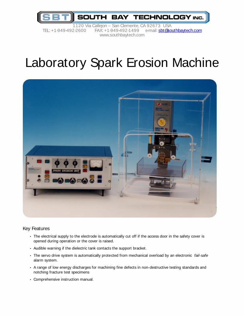
1120 Via Callejon – San Clemente, CA 92673 USA TEL: +1-949-492-2600 FAX: +1-949-492-1499 e-mail: [email protected] www.southbaytech.com Laboratory Spark Erosion Machine Key Features • The electrical supply to the electrode is automatically cut off if the access door in the safety cover is opened during operation or the cover is raised. • Audible warning if the dielectric tank contacts the support bracket. • The servo drive system is automatically protected from mechanical overload by an electronic fail-safe alarm system. • A range of low energy discharges for machining fine defects in non-destructive testing standards and notching fracture test specimens • Comprehensive instruction manual.
Transcript of Laboratory Spark Erosion Machine - Testbourne · 2015-12-27 · Laboratory Spark Erosion machine...
1120 Via Callejon – San Clemente, CA 92673 USA TEL: +1-949-492-2600 FAX: +1-949-492-1499 e-mail: [email protected]
www.southbaytech.com
Laboratory Spark Erosion Machine
Key Features
• The electrical supply to the electrode is automatically cut off if the access door in the safety cover is opened during operation or the cover is raised.
• Audible warning if the dielectric tank contacts the support bracket.
• The servo drive system is automatically protected from mechanical overload by an electronic fail-safe alarm system.
• A range of low energy discharges for machining fine defects in non-destructive testing standards and notching fracture test specimens
• Comprehensive instruction manual.
Specification
The Mk 4 Spark erosion machine has two orthogonal micrometers for positioning the electrode. The machining process is servo controlled. It is supplied as a ready to use system comprising: water deioniser, dielectric pump, small sample mounting system, collet for 3mm tubular electrodes, pin chuck for small diameter rod, a set of miniature G clamps and a tubular electrode for trepanning 3mm discs.
Order code – MS-534B
Dimensions mm Height Width Depth Weight kg
Machining head 305 100 100 2.7
Head & stand 585 250 380 12.2
Power supply 215 535 405 17.3
Safety cover 610 470 510 9.5
Mains electrical supply 110-120 v ac 60Hz 220-240 v ac 50Hz
Standard Optional
Power consumption 500 VA Maximum
Output (off-load) voltage 80-350 v In four ranges
Energy control 36 settings For each voltage range
Auxiliary power outlets (12 v dc) 1 1
For dielectric pump Inspection lamp (optional)
Optional Accessories Order code
• Wire cutting stage (motor driven) MS-500
• Turret machine vice MS-600
• Strip clamp MS-301
• Sample holder (single end) MS-306
• Sample holder (double end) MS-307
• Holder for thin sheet electrodes MS-304
Water Deioniser
Small Sample Mounting System
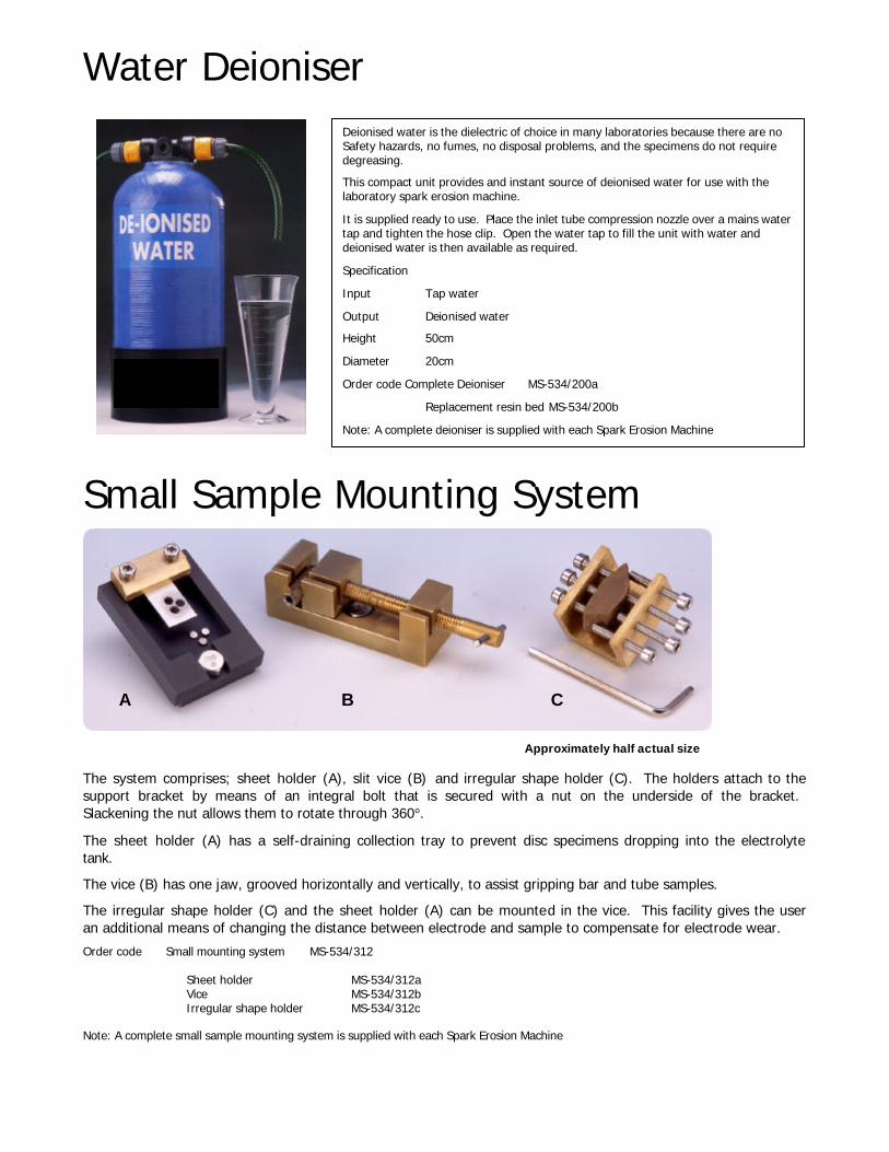
The system comprises; sheet holder (A), slit vice (B) and irregular shape holder (C). The holders attach to the support bracket by means of an integral bolt that is secured with a nut on the underside of the bracket. Slackening the nut allows them to rotate through 360°.
The sheet holder (A) has a self-draining collection tray to prevent disc specimens dropping into the electrolyte tank.
The vice (B) has one jaw, grooved horizontally and vertically, to assist gripping bar and tube samples.
The irregular shape holder (C) and the sheet holder (A) can be mounted in the vice. This facility gives the user an additional means of changing the distance between electrode and sample to compensate for electrode wear.
Order code Small mounting system MS-534/312
Sheet holder MS-534/312a Vice MS-534/312b Irregular shape holder MS-534/312c
Note: A complete small sample mounting system is supplied with each Spark Erosion Machine
Deionised water is the dielectric of choice in many laboratories because there are no Safety hazards, no fumes, no disposal problems, and the specimens do not require degreasing.
This compact unit provides and instant source of deionised water for use with the laboratory spark erosion machine.
It is supplied ready to use. Place the inlet tube compression nozzle over a mains water tap and tighten the hose clip. Open the water tap to fill the unit with water and deionised water is then available as required.
Specification
Input Tap water
Output Deionised water
Height 50cm
Diameter 20cm
Order code Complete Deioniser MS-534/200a
Replacement resin bed MS-534/200b
Note: A complete deioniser is supplied with each Spark Erosion Machine
A B C
Approximately half actual size
David Henriks
Black Box
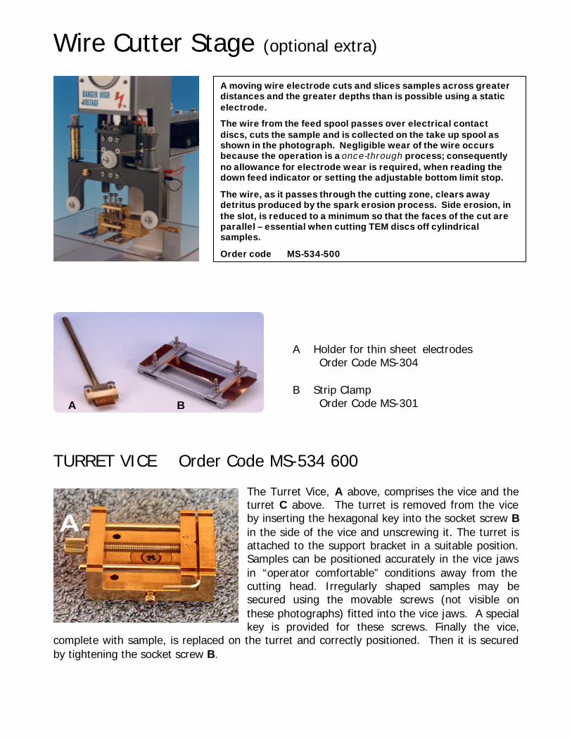
Wire Cutter Stage (optional extra) A Holder for thin sheet electrodes
Order Code MS-304 B Strip Clamp
Order Code MS-301
TURRET VICE Order Code MS-534 600
The Turret Vice, A above, comprises the vice and the turret C above. The turret is removed from the vice by inserting the hexagonal key into the socket screw B in the side of the vice and unscrewing it. The turret is attached to the support bracket in a suitable position. Samples can be positioned accurately in the vice jaws in “operator comfortable” conditions away from the cutting head. Irregularly shaped samples may be secured using the movable screws (not visible on these photographs) fitted into the vice jaws. A special key is provided for these screws. Finally the vice,
complete with sample, is replaced on the turret and correctly positioned. Then it is secured by tightening the socket screw B.
The wire cutter stage is mounted on the servo base plate of the cutting head in place of the fixed electrode holder.
A moving wire electrode cuts and slices samples across greater distances and the greater depths than is possible using a static electrode.
The wire from the feed spool passes over electrical contact discs, cuts the sample and is collected on the take up spool as shown in the photograph. Negligible wear of the wire occurs because the operation is a once-through process; consequently no allowance for electrode wear is required, when reading the down feed indicator or setting the adjustable bottom limit stop.
The wire, as it passes through the cutting zone, clears away detritus produced by the spark erosion process. Side erosion, in the slot, is reduced to a minimum so that the faces of the cut are parallel – essential when cutting TEM discs off cylindrical samples.
Order code MS-534-500
A B
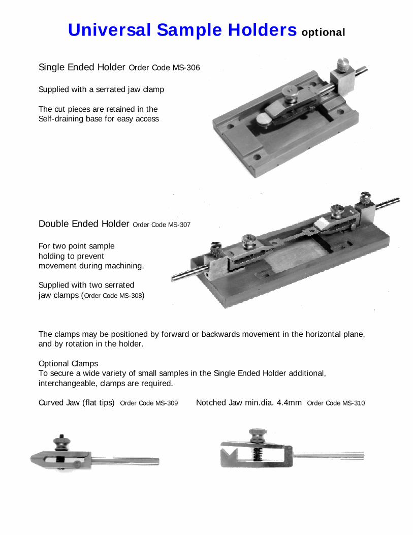
Universal Sample Holders optional Single Ended Holder Order Code MS-306 Supplied with a serrated jaw clamp The cut pieces are retained in the Self-draining base for easy access Double Ended Holder Order Code MS-307 For two point sample holding to prevent movement during machining. Supplied with two serrated jaw clamps (Order Code MS-308) The clamps may be positioned by forward or backwards movement in the horizontal plane, and by rotation in the holder. Optional Clamps To secure a wide variety of small samples in the Single Ended Holder additional, interchangeable, clamps are required. Curved Jaw (flat tips) Order Code MS-309 Notched Jaw min.dia. 4.4mm Order Code MS-310
REASONS FOR PURCHASING THE LABORATORY SPARK EROSION MACHINE
The machine is supplied as a “ready to use” package with sample holders, clamps, pin chuck, water deioniser and an electrode for trepanning 3 mm diameter TEM discs. No special electric power supply is required, only one standard 13 amp ac power socket. The user has direct control of the time scale. No waiting for the workshop to machine specimens. The user has direct control of the machining. No mixed up samples. No previous knowledge of spark erosion machining is required. The comprehensive instruction manual is easy to understand. The dielectric is deionised water. No problems of disposal, no need to degrease the specimens and no risk of skin disorders caused by immersion in Kerosene and oils. Use of the machine can be controlled – the Power Supply cannot be energised until a key (two keys are supplied with each machine) is inserted into the mains switch and turned. The machine is safe for students to operate because the cutting head is totally enclosed. If the door is opened, or the cover raised during machining, an infra red beam is broken and the high-tension supply is cut off automatically. It cannot be restored until the cover is lowered and/or door is closed. The servo drive is protected from damage by electronic circuitry that detects overload, switches off the drive and sounds alarm. Very hard and very soft materials, eg tungsten and lead and electrically conducting ceramics, eg Silicon Carbide, Boron carbide and thin diamond layers can be machined. The consumable, brass wire and copper tube are readily available. The machine can be adaptabed for special needs e.g. the cutting head can be mounted directly onto large metal structures for removing small specimens or making defects for fracture testing. A larger dielectric tank may be fitted. The Laboratory Spark Erosion Machine has sufficient power to machine most of the samples used in transmission and optical microscopy. It can also be used to machine small tensile specimens from thin walled tubes and strip.
1120 Via Callejon – San Clemente, CA 92673 USA
TEL: +1-949-492-2600 FAX: +1-949-492-1499 e-mail: [email protected] www.southbaytech.com
Specimen preparation using the Laboratory Spark Erosion machine
General Sectioning and TrepanningGeneral Sectioning and Trepanning The examples shown on the following pages demonstrate the versatility of spark erosion machining in a variety of applications. Fracture and Fatigue Testing Internal notches that have the profile of “natural flaws” can be produced in fracture specimens by using similarly shaped electrodes. Sharp surface cracks can be made at the root of a notch in a fracture/fatigue specimen
Production of Sheet Tensile Specimens
These can be machined from sheet up to 1mm thick
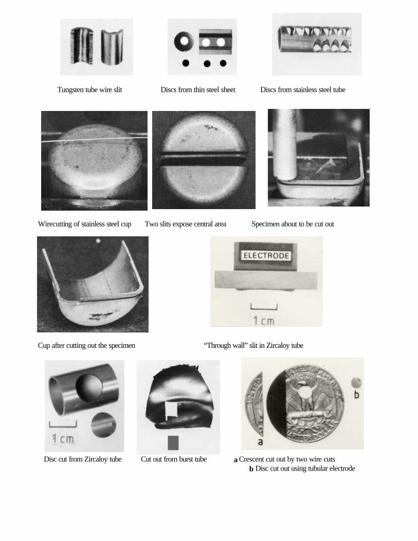
Tungsten tube wire slit Discs from thin steel sheet Discs from stainless steel tube
Wirecutting of stainless steel cup Two slits expose central area Specimen about to be cut out
Cup after cutting out the specimen “Through wall” slit in Zircaloy tube
Disc cut from Zircaloy tube Cut out from burst tube a Crescent cut out by two wire cuts b Disc cut out using tubular electrode
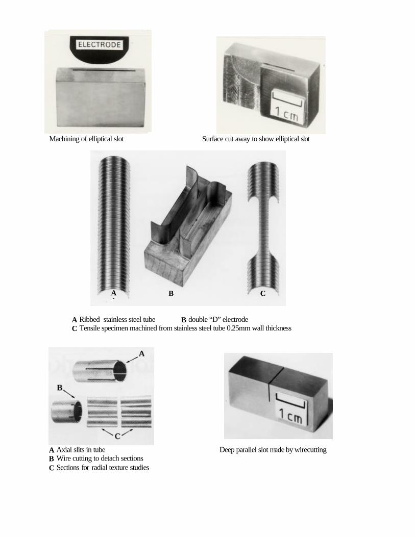
Machining of elliptical slot Surface cut away to show elliptical slot
A Ribbed stainless steel tube B double “D” electrode C Tensile specimen machined from stainless steel tube 0.25mm wall thickness
A Axial slits in tube Deep parallel slot made by wirecutting B Wire cutting to detach sections C Sections for radial texture studies
AA
B C