Laboratory Fume Hoods - RDM Industrial Products€¦ · RDM / Laboratory Fume Hoods ... 17 Local...
42
RDM Laboratory Fume Hoods SEFA SCIENTIFIC EQUIPMENT & FURNITURE ASSOCIATION
Transcript of Laboratory Fume Hoods - RDM Industrial Products€¦ · RDM / Laboratory Fume Hoods ... 17 Local...
RDM Laboratory Fume Hoods
SEFA SCIENTIFIC
EQUIPMENT & FURNITURE
ASSOCIATION
RDM / Laboratory Fume Hoods
ADA Fume Hoods.............................................................12 Demonstration Fume Hood....................................................22
ADA Fume Hood Assemblies............................................13 Drains.................................................................................... 30
SB-MAX-A Add Air Fume Hoods................................... 10 Electrical Fixtures................................................................... 29
SB-MAX-A Add Air Fume Hood Assemblies...................11 Filler Panels............................................................................26
SB-MAX Bypass Fume Hoods.......................................... 6 Filters.....................................................................................32
SB-MAX Bypass Fume Hood Assemblies.......... ............. 7 Fire Extinguishers..................................................................31
Low Bench Fume Hoods....................................................18 Flow Patterns......................................................................... 3
Low Bench Fume Hood Assemblies.................................19 Introduction........................................................................... 2
Perchloric Acid Fume Hoods............................................ 16 Lattice Assemblies.................................................................32
Perchloric Acid Fume Hood Assemblies...........................17 Local Exhaust.........................................................................33
Radio Isotope Fume Hoods................................................14 Material Options.....................................................................31
Radio Isotope Fume Hood Assemblies..............................15 Planning................................................................................. 5
VB-MAX Variable Volume Fume Hoods............................. 8 Plumbing Rough-In................................................................35
VB-MAX Variable Volume Fume Hood Assemblies............ 9 Portable Fume Hood...............................................................23
Walk-In Fume Hoods.........................................................18 Sash Options..........................................................................27
Walk-In Fume Hood Assemblies........................................19 Service Fixtures.......................................................................28
Alarms................................................................................... 28 Sinks...................................................................................... 30
Anemometer..............................................................................32 Smoke....................................................................................32
Baffle Options......................................................................... 31 Specifications....................................................................36-37
Base Cabinets......................................................................... 26 Spray Booth....................................................................... 24-25
Baths.......................................................................................30 Thin Wall Fume Hood............................................................20
Blowers..............................................................................33-34 Thin Wall Fume Hood Assemblies........................................21
Canopy Hoods.........................................................................26 Transitions..............................................................................33
Ceiling Enclosures..................................................................27 Traps........................................................................................30
Countertops.............................................................................29 Vent Kits..................................................................................31
Definitions.............................................................................38 Wash Down............................................................................33
Y Branches............................................................................. 33
1
Table of Contents
Airfoil

Introduction GENERAL – The name RDM has long been synonymous with quality and longevity. Our Fume Hood Product Line is a great example of the top quality products we have to offer. Backed by over 50 years of exper ience and st a te-of- th e-ar t engineering and testing facilities, w e c a n provide you with a Fume Hood unsurpassed in quality and performance.
TESTING – Safety should be the number one concern when choosing a Fume Hood. That is why RDM tests and certifies each style Fume Hood in accordance with the current ASHRAE method of testing performance of laboratory Fume Hoods.
The ASHRAE 110 test procedure is an industry standard, r ecogn ized by SEFA and the American Conference of Governmental Industrial Hygienists, for safe Fume Hood performance.
DESIGN – The design of the RDM Fume Hood provides you wi t h ma x i m um sa fe t y at mi n i mum cos t . Incorporating standard options, such as combination sashes and sash stops, allows you to maintain face velocities while exhausting less air. Hence, the RDM Fume Hood costs less to operate than other conventional units.
2
RDM / Laboratory Fume Hoods
REFERENCES – The American Industrial Hygiene Association, The American Conferences of Governmental Industrial Hygienists and the American Society of Heating, Refrigerating and Air-Conditioning Engineershave all published guidelines on Fume Hood face velocities and operating procedures.
Because the performance of a Fume Hood is greatly affected by the surrounding conditions, the recommendations in this catalog are based on normal or average conditions. For recommendations on ideal or extreme conditions, the guidelines published by the above referenced agencies should be followed.
SPECIFICATIONS – RDM Fume Hoods are manufacturedin strict accordance with the specifications shown in thiscatalog. However, continuous testing and research mayresult in design and specification changes without advance notice.
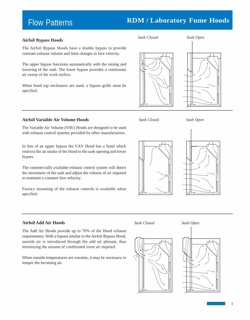
Flow Patterns Airfoil Bypass Hoods
The Airfoil Bypass Hoods have a double bypass to provide constant exhaust volume and limit changes in face velocity.
The upper bypass functions automatically with the raising and lowering of the sash. The lower bypass provides a continuous air sweep of the work surface.
When hood top enclosures are used, a bypass grille must be specified.
Airfoil Variable Air Volume Hoods
The Variable Air Volume (VAV) Hoods are designed to be used with exhaust control systems provided by other manufacturers.
In lieu of an upper bypass the VAV Hood has a lintel which restricts the air intake of the Hood to the sash opening and lower bypass.
The commercially available exhaust control system will detect the movement of the sash and adjust the volume of air required to maintain a constant face velocity.
Factory mounting of the exhaust controls is available when specified.
Airfoil Add Air Hoods
The Add Air Hoods provide up to 70% of the Hood exhaust requirements. With a bypass similar to the Airfoil Bypass Hood, outside air is introduced through the add air plenum, thus minimizing the amount of conditioned room air required.
When outside temperatures are extreme, it may be necessary to temper the incoming air.
3
RDM / Laboratory Fume Hoods
Sash Closed Sash Open
Sash Closed Sash Open
Sash Closed Sash Open

RDM / Laboratory Fume Hoods Air Conditioning
Register
Air Conditioning Registers
Base Cabinets
Sealed Windows
Figure 1 Good Locations
Fume Hood Selection There are two main factors to consider when selecting a Fume Hood style.
First consider the type of work being performed in the Hood. The use of perchloric acid or radioactive materials requires a Fume Hood specifically designed for these materials. Large apparatus or complex set-ups may require the use of a low bench or walk-in Fume Hood to accommodate the space requirements.
The second consideration in selecting a Fume Hood style is the air consumption of the hood. Operation of a Fume Hood requires a relatively large volume of room air.
If you determine that the amount of air being supplied to the room is adequate to accommodate the exhaust volume of the Fume Hood the ByPass style Fume Hood would be an excellent choice.
If there is not enough supply air available, the Add Air style may be the right choice.
The Variable Air Volume style Fume Hood is designed to be used with an adjustable damper system in the ductwork. The use of this Hood will, when used in conjunction with a VAV control system, drastically reduce the total amount of air consumed. This makes the Variable Air Volume style Hood a good choice when trying to reduce air consumption for energy cost savings or when there simply is not enough available supply air.
For more information see “Flow Patterns” on Page 3. Fume Hood Locations Location of the Fume Hood is of prime importance, since a variety of conditions will affect the performance of the Hood.
When selecting a location for the Fume Hood, operator convenience, work flow and exhaust duct locations should all be considered. In addition, an attempt should be made to keep the hood away from the line of traffic. It is both inconvenient and dangerous to install a Fume Hood so that the operator is forced to work in the line of traffic movement.
4
Line of
Traffic
Hood
Line of
Traffic
Hood
Center Table
Base Cabinets
Base Cabinets
Line of
Traffic
Hood
Center Table
Sealed Windows
Figure 2 Poor Locations The presence of cross-drafts will adversely affect the performance or the Fume Hood. For this reason it is a good ideanot to locate the Fume Hood near open doors and windows. High velocity air diffusers located directly in front ofthe Fume Hood could actually draw fumes out of the Hood andinto the room. Although there is no single preferred method fordelivery of make-up air, it is a good idea to locate the Fume Hoodas far from the air diffuser as possible so that the air first sweepsthrough the laboratory working area and then into the Fume Hood.
Fume Hood Velocity Selection Selection of the Fume Hood face velocity should be directly re-lated to the location of the Fume Hood. A Fume Hood in a goodlocation, as shown in Fig. 1, should operate properly at a face velocity of 75 FPM. A poorly located Fume Hood, as shown inFig. 2, may require a face velocity of 125 FPM to maintain properperformance.
Since most fume hood installations require some type of location compromise, a face velocity of 100 FPM is usually the norm. Fume Hoods with a high heat source may re-quire slightly higher face velocities.
OSHA calls for, but does not require, a face velocity of 150 FPMfor Fume Hoods used with any of the 13 carcinogens listed in OSHA 1910.1003 et seq. (OSHA 1978). Studies have shown thathoods operated at face velocities of 150 FPM and greater often perform poorer than if operated at a lower face velocity, due to disruptive air turbulence at the perimeter of the Hood opening and in the wake of objects placed inside the work area of the Hood.
Fume Hood Blowers & Ductwork The blower and ductwork control the amount of air moving throughthe Fume Hood. For this reason it is extremely important that theybe installed and maintained properly.
By using the chart on page 34, you can choose the correct blowerfor the Fume Hood you have selected.
Planning Line of
Traffic
CenterTable
Hood
Planning
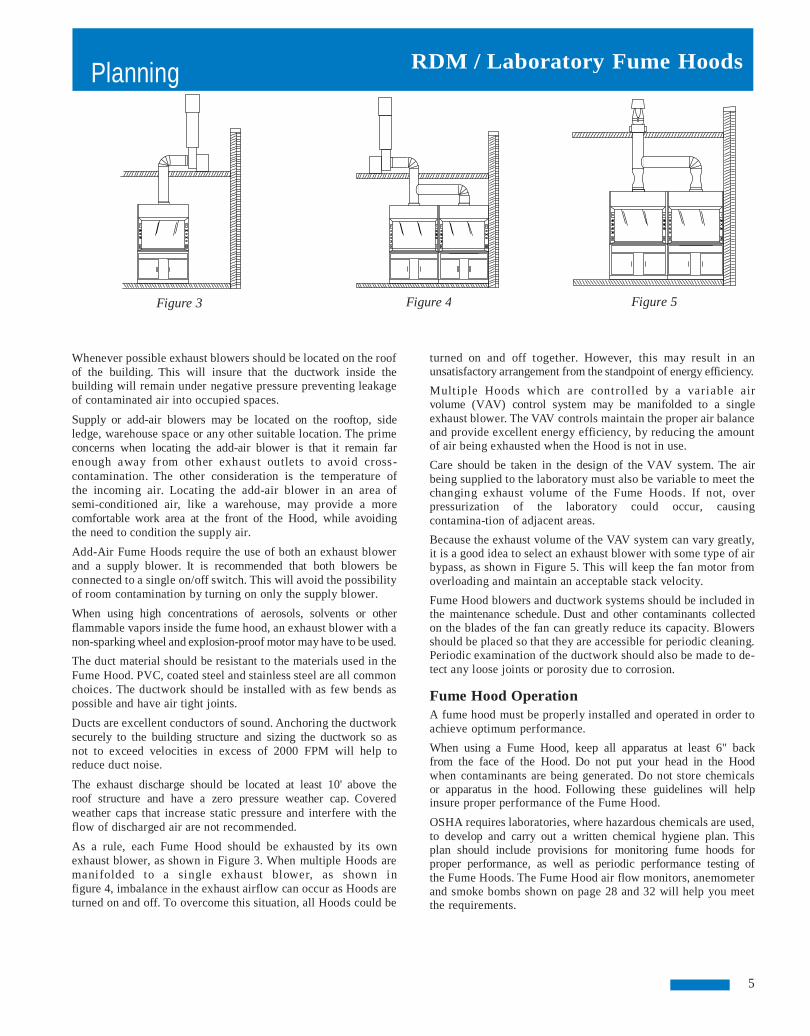
Figure 3
Whenever possible exhaust blowers should be located on the roof of the building. This will insure that the ductwork inside the building will remain under negative pressure preventing leakage of contaminated air into occupied spaces.
Supply or add-air blowers may be located on the rooftop, side ledge, warehouse space or any other suitable location. The prime concerns when locating the add-air blower is that it remain far enough away from other exhaust outlets to avoid cross-contamination. The other consideration is the temperature of the incoming air. Locating the add-air blower in an area of semi-conditioned air, like a warehouse, may provide a more comfortable work area at the front of the Hood, while avoiding the need to condition the supply air.
Add-Air Fume Hoods require the use of both an exhaust blower and a supply blower. It is recommended that both blowers be connected to a single on/off switch. This will avoid the possibility of room contamination by turning on only the supply blower.
When using high concentrations of aerosols, solvents or other flammable vapors inside the fume hood, an exhaust blower with a non-sparking wheel and explosion-proof motor may have to be used.
The duct material should be resistant to the materials used in the Fume Hood. PVC, coated steel and stainless steel are all common choices. The ductwork should be installed with as few bends as possible and have air tight joints.
Ducts are excellent conductors of sound. Anchoring the ductwork securely to the building structure and sizing the ductwork so as not to exceed velocities in excess of 2000 FPM will help to reduce duct noise.
The exhaust discharge should be located at least 10' above the roof structure and have a zero pressure weather cap. Covered weather caps that increase static pressure and interfere with the flow of discharged air are not recommended.
As a rule, each Fume Hood should be exhausted by its own exhaust blower, as shown in Figure 3. When multiple Hoods are manifolded to a single exhaust blower, as shown in figure 4, imbalance in the exhaust airflow can occur as Hoods are turned on and off. To overcome this situation, all Hoods could be
RDM / Laboratory Fume Hoods
Figure 5 Figure 4
turned on and off together. However, this may result in an unsatisfactory arrangement from the standpoint of energy efficiency.
Multiple Hoods which are controlled by a variable air volume (VAV) control system may be manifolded to a single exhaust blower. The VAV controls maintain the proper air balanceand provide excellent energy efficiency, by reducing the amountof air being exhausted when the Hood is not in use.
Care should be taken in the design of the VAV system. The air being supplied to the laboratory must also be variable to meet thechanging exhaust volume of the Fume Hoods. If not, over pressurization of the laboratory could occur, causingcontamina-tion of adjacent areas.
Because the exhaust volume of the VAV system can vary greatly,it is a good idea to select an exhaust blower with some type of airbypass, as shown in Figure 5. This will keep the fan motor fromoverloading and maintain an acceptable stack velocity.
Fume Hood blowers and ductwork systems should be included inthe maintenance schedule. Dust and other contaminants collected on the blades of the fan can greatly reduce its capacity. Blowersshould be placed so that they are accessible for periodic cleaning.Periodic examination of the ductwork should also be made to de-tect any loose joints or porosity due to corrosion.
Fume Hood Operation A fume hood must be properly installed and operated in order toachieve optimum performance.
When using a Fume Hood, keep all apparatus at least 6" back from the face of the Hood. Do not put your head in the Hood when contaminants are being generated. Do not store chemicalsor apparatus in the hood. Following these guidelines will help insure proper performance of the Fume Hood.
OSHA requires laboratories, where hazardous chemicals are used,to develop and carry out a written chemical hygiene plan. Thisplan should include provisions for monitoring fume hoods for proper performance, as well as periodic performance testing of the Fume Hoods. The Fume Hood air flow monitors, anemometerand smoke bombs shown on page 28 and 32 will help you meetthe requirements.
5

SB-MAX Airfoil Bypass Fume Hoods
Continuous air flow across the work surface of the Airfoil Bypass Fume Hood exhausts potentially hazardous vapors safely away from the work environment, even with the sash closed!
The Airfoil Bypass Fume Hood features an internal bypass opening located above the sash allowing for a constant exhaust volume while maintaining the face velocity. In operation, the bypass works automatically, in conjunction with the hood sash. The bypass adjustment is made as the sash is opened and closed creating a relatively constant face velocity regardless of sash position.
Design
The Bypass Fume Hood comes equipped with a full view sash providing an unobstructed view of the Hood interior work area. The sash, a glazed 7/32" thick laminated safety glass is provided with a full width flush pull. A counterweight provides for one finger operation of the sash at any position.
The entrance of the Hood is framed with inward-angled members. This angled frame works to minimize turbulence and provide smooth movement of air into the Hood, resulting in a more efficient operation of the Fume Hood at face velocities ranging from 60 to 150 FPM. A lower airfoil sash stop maintains a 1" space (below closed sash) that allows air to flow continuously across the work surface inside the Hood.
Double wall construction of the Hood superstructure allows for easy installation of service fixtures and routing of interior plumbing and electrical lines. The interior of the Airfoil Bypass Fume Hood is white “Resin-Chem.” Removable access panels on both interior sides of the Hood are standard features. The exterior superstructure side panels are also removable for easy access to service fixtures and supply lines.
Fume Hood Superstructures are available in widths from 48" to 96", including RDM's unique 84" wide model as shown below. Service and electrical fixtures shown are optional and must be ordered separately.
SB-605 60" SB-606 72"
RDM / Laboratory Fume Hoods
Interior Lighting A maximum width, two tube fluorescent light fixture, complete with tubes, is provided with the Airfoil Bypass Fume Hood. The light fixture is mounted above a sealed safety glass panel isolating it from corrosive fumes and hazardous vapors. Tube lights are easily replaced throughthe top front of the Fume Hood superstructure.
Options A variety of optional service fixtures are available from RDM for installation in the Bypass Fume Hood. OurRDM representatives work closely with customers inspecifying the type of fixtures and electrical receptaclesrequired.
SB-607 84" SB-608 96" SB-604 48" SB-603 36” 6

SB-MAX Airfoil Bypass Assemblies
Airfoil Bypass Fume Hood Assemblies The five standard Fume Hood sizes are each available as a complete assembly.
Detailed information on base cabinets, countertops and service fixtures is shown on pages 26, 28 and 29.
The assembly for the 48" and 60" wide Hoods consists of a standard base cabinet, two LF35-7 filler panels, dished
SB-9040 48" SB-9050 60" SB-9060 72" SB-9070 84" SB-9080 96"
75 FPM 100 FPM 125 FPM 150 FPM
CFM S.P. CFM S.P. CFM S.P. CFM S.P.
650 .22 867 .39 1083 .61 1300 .87
850 .21 1133 .38 1417 .59 1700 .85
1050 .21 1400 .37 1750 .58 2100 .84
1250 .21 1667 .37 2083 .58 2500 .83
1450 .25 1933 .45 2417 .71 2900 1.02
The static pressures listed above are for the hoods only. An appropriate amount will have to be added to this figure to compensate for the pressure drop through the duct system. The total pressure drop through the hood and the duct system must be known to select the proper exhaust blower.
36"
26 1/2"
1" Duct collar locations are as shown above. The center line of each collar is 8" from the back of the hood. The area indicated by the dashed lines is designated for plumbing and electrical rough-ins. All rough-ins should be kept within 7" of the wall and 18" from the floor.
7
Rough-in Details
33 7/8"
8"
RDM / Laboratory Fume Hoods
epoxy resin countertop, F-400 3" x 6" epoxy resin cup sink,six F-100 service fixtures, F-110 cold water fixture, F-200light switch, F-210 blower switch and two F-220 110Vduplexes.
72", 84" and 96" assemblies include all of the above alongwith a second base cabinet, cup sink and water fixture.
All service and electrical fixtures are furnished, but not installed.
HOOD COLLAR SIZE SIZE
48" 6" x 12"
60" 6" x 16"
72" 6" x 20"
84" (2)6" x 12"
96" (2)6" x 12"
26 1/2"
30"
23 1/2"
24"
23 1/2"
SB-607
SB-606
SB-605
SB-608
SB-604
7" 22"
30"

VB-MAX Airfoil Variable Volume Fume Hoods
The Variable Volume Fume Hood is specifically designed for use with exhaust control systems provided by other manufacturers that monitor and control the amount of air being exhausted from the Hood. The use of these devices will maintain a constant face velocity and greatly reduce the operating cost of the Fume Hood.
Design
A lintel at the upper front of the superstructure restricts the Hood air intake to the front sash opening. By incorporating any one of a number of commercially available VAV controls, the exhaust volume of the Hood can be varied to maintain a specified face velocity regardless of sash position.
The full view sash provides a clear, unobstructed view of the work surface and when fully opened, allows easy access to all areas of the Hood interior. The sash is counterweighted for easy up/down operation and is made of 7/32" laminated safety glass with a full width flush pull.
The lower airfoil acts as a sash stop designed to provide a 1" gap (with sash closed) allowing air to continuously sweep the countertop of the Fume Hood.
Double side wall Hood construction provides adequate space for mounting service fixtures. The interior “Resin-Chem” lining has removable access panels on either side providing easy access for installation and maintenance of service and electrical fixtures. Both exterior side panels of the Hood superstructure are also removable for access to lines.
Fume Hood Superstructures are available in widths from 48" to 96", including RDM's unique 84" wide model as shown below. Service and electrical fixtures shown are optional and must be ordered separately.
VB-615 60" VB-616 72" VB-617 84" VB-618 96"
RDM / Laboratory Fume Hoods
Interior Lighting A twin tube fluorescent light fixture provides illuminationof the Hood's interior surfaces. The fixture is recessed intothe interior Hood ceiling and protected behind a sealed safetyglass panel away from hazardous vapors and corrosive fumes. Tubes (included with Hood purchase) are easily replaced from the outside of the Hood superstructure.
Options A variety of optional service fixtures are available from RDM for installation in the Variable Volume Fume Hood.Mounting holes for fixtures and electrical receptacles arepre-cut and capped when fixtures are not required.
VB-614 48"
8
VB-MAX Airfoil Variable Volume Assemblies
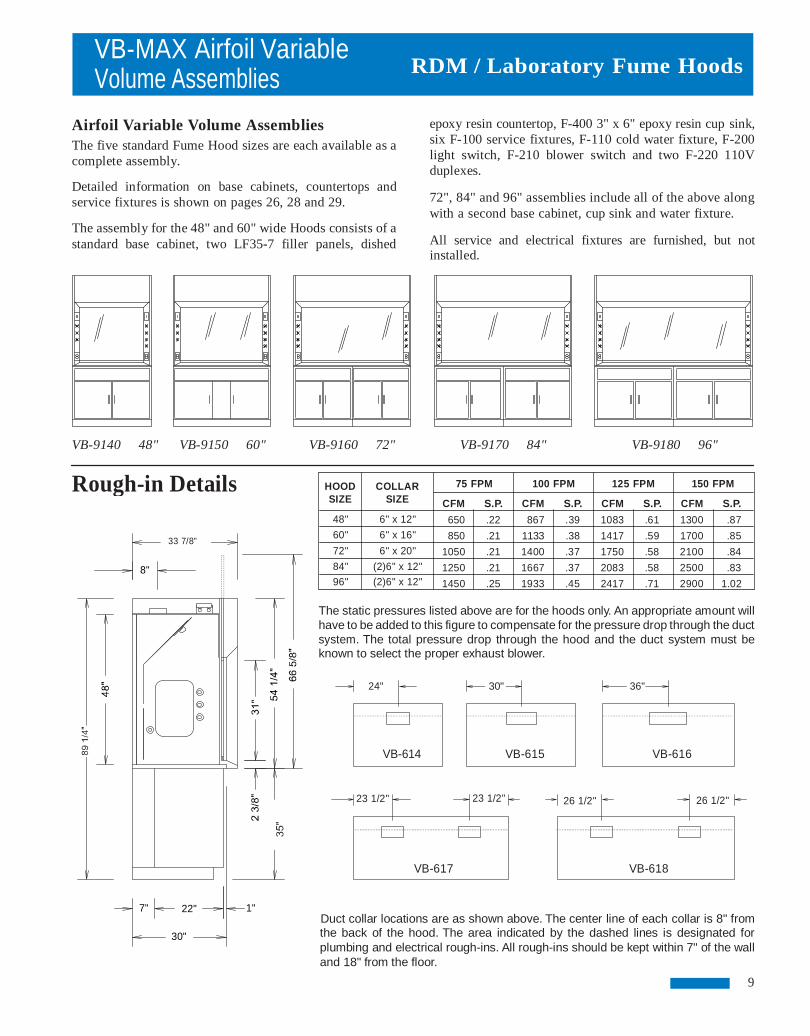
Airfoil Variable Volume Assemblies The five standard Fume Hood sizes are each available as a complete assembly.
Detailed information on base cabinets, countertops and service fixtures is shown on pages 26, 28 and 29.
The assembly for the 48" and 60" wide Hoods consists of a standard base cabinet, two LF35-7 filler panels, dished
VB-9140 48" VB-9150 60" VB-9160 72" VB-9170 84" VB-9180 96"
75 FPM 100 FPM 125 FPM 150 FPM
CFM S.P. CFM S.P. CFM S.P. CFM S.P.
650 .22 867 .39 1083 .61 1300 .87
850 .21 1133 .38 1417 .59 1700 .85
1050 .21 1400 .37 1750 .58 2100 .84
1250 .21 1667 .37 2083 .58 2500 .83
1450 .25 1933 .45 2417 .71 2900 1.02
The static pressures listed above are for the hoods only. An appropriate amount will have to be added to this figure to compensate for the pressure drop through the duct system. The total pressure drop through the hood and the duct system must be known to select the proper exhaust blower.
36"
26 1/2"
1" Duct collar locations are as shown above. The center line of each collar is 8" from the back of the hood. The area indicated by the dashed lines is designated for plumbing and electrical rough-ins. All rough-ins should be kept within 7" of the wall and 18" from the floor.
9
HOOD COLLAR SIZE SIZE
48" 6" x 12"
60" 6" x 16"
72" 6" x 20"
84" (2)6" x 12"
96" (2)6" x 12"
26 1/2"
30"
23 1/2"
24"
23 1/2"
VB-618
VB-614
VB-616
VB-617
VB-615
Rough-in Details
33 7/8"
8"
7" 22"
30"
RDM / Laboratory Fume Hoods
epoxy resin countertop, F-400 3" x 6" epoxy resin cup sink,six F-100 service fixtures, F-110 cold water fixture, F-200light switch, F-210 blower switch and two F-220 110Vduplexes.
72", 84" and 96" assemblies include all of the above alongwith a second base cabinet, cup sink and water fixture.
All service and electrical fixtures are furnished, but not installed.

SB-MAX-A Airfoil Add Air Fume Hoods
The RDM Airfoil Add Air Fume Hood provides added economy through the use of a front mount “add air plenum” that can supply up to 70 percent of the total Hood air volume requirement from an outside source.
Design
The superstructure entrance of the Add Air Fume Hood is framed with inward angled members that minimize turbulence and provide smooth movement of air into the Hood. This design allows for efficient operation of the Fume Hood at face velocities ranging from 60 to 150 FPM. Additionally, the built-in bypass feature above the Hood sash works to maintain a relatively constant face velocity at any sash position. The front mounted add air plenum of the Airfoil Add Air Fume Hood utilizes a series of diffusers and louvers to provide a uniform flow of supply air to the face of the Fume Hood. This uniform air flow allows for providing up to 70% of the overall air volume requirements of the Hood through the add air plenum. As with other RDM Fume Hoods, the Add Air Hood comes equipped with a full view laminated safety glass sash with a full width flush pull and counterweight for easy operation. A lower airfoil acts as sash stop that provides a 1" space for air to continuously flow into the Hood and across the work surface. Double wall construction of the superstructure provides adequate space on both sides of the Hood for installation of service fixtures and routing of plumbing and electrical lines. The lining of the interior work area of the Hood is white Resin-Chem with removable interior access panels on both sides. Removable exterior side panels provide easy access to fixtures and their service lines.
Fume Hood Superstructures are available in widths from 48" to 96", including RDM's unique 84" wide model as shown below. Service and electrical fixtures shown are optional and must be ordered separately.
SB-626-A 72" SB-627-A 84" SB-628-A 96"
RDM / Laboratory Fume Hoods
Interior Lighting The interior of the Add Air Fume Hood is brightly lit by a maximum width dual fluorescent tube light fixture. The fixtureis mounted behind a sealed safety glass panel to isolate the fixture from corrosive fumes and flammable vapors. Replacement of fluorescent tubes is accomplished from the exterior top front of the Fume Hood superstructure.
Options Choose from the variety of optional service fixtures availablefrom RDM. Service fixture and electrical outlet types and locations are to be specified by the customer to fit each particular application. Mounting holes are provided in the superstructure for final on-site installation of optional equipment.
SB-624-A 48" SB-623-A 36”
10
SB-625-A 60"

SB-MAX-A Airfoil Add Air Assemblies
Airfoil Add Air Hood Assemblies The five standard Fume Hood sizes are each available as a complete assembly.
Detailed information on base cabinets, countertops and service fixtures is shown on pages 26, 28 and 29.
The assembly for the 48" and 60" wide Hoods consists of a standard base cabinet, two LF35-7 filler panels, dished SB-9240-A 48" SB-9250-A 60" SB-9260-A 72" SB-9270-A 84" SB-9280-A 96"
COLLAR SIZE
6" x 12" 6" x 12" 6" x 16" 6" x 16" 6" x 20" 6" x 20"
(2)6" x 12" (2)6" x 12" (2)6" x 12" (2)6" x 14"
The static pressures listed above are for the hoods only. An appropriate amount will have to be added to this figure to compensate for the pressure drop through the duct system. The total pressure drop through the hood and the duct system must be known to select the proper exhaust blower. Supply figures are based on 70% add air.
24"
23 1/2"
1"
Duct collar locations are as shown above. The center line of each collar is 8" from the back of the hood. The center line of the supply duct is 35 5/8" from the back of the hood. The area indicated by the dashed lines is designated for plumbing and electrical rough-ins. All rough-ins should be kept within 7" of the wall and 18" from the floor.
11
RDM / Laboratory Fume Hoods
epoxy resin countertop, F-400 3" x 6" epoxy resin cup sink,six F-100 service fixtures, F-110 cold water fixture, F-200light switch, F-210 blower switch and two F-220 110Vduplexes.
72", 84" and 96" assemblies include all of the above alongwith a second base cabinet, cup sink and water fixture.
All service and electrical fixtures are furnished, but not installed.
CFM 1300 910
1700 1190 2100 1470 2500 1750 2900 2030
75 FPM 100 FPM 125 FPM 150 FPM CFM S.P. 650 .22 455 .17 850 .21 595 .17
1050 .21 735 .17
1250 .21 875 .15
1450 .25 1015 .17
EXH SUP EXH SUP EXH SUP EXH SUP EXH SUP
S.P. .61 .48 .59 .47 .58 .46 .58 .46 .71 .49
S.P. .87 .69 .85 .69 .84 .68 .83 .71
1.02 .71
HOOD SIZE
48"
60"
72"
84"
96"
CFM S.P. 867 .39 607 .30
1133 .38 793 .29
1400 .37 980 .31
1667 .37 1167 .29 1933 .45 1353 .31
CFM 1083 758
1417 992
1750 1225 2083 1458 2417 1691
26 1/2"
36"
26 1/2"
30"
23 1/2"
SB-628-A
SB-626-A
SB-624-A
SB-627-A
SB-625-A
Rough-in Details
40 7/8"
35 5/8"
8"
7" 22"
30"
Airfoil ADA Fume Hoods
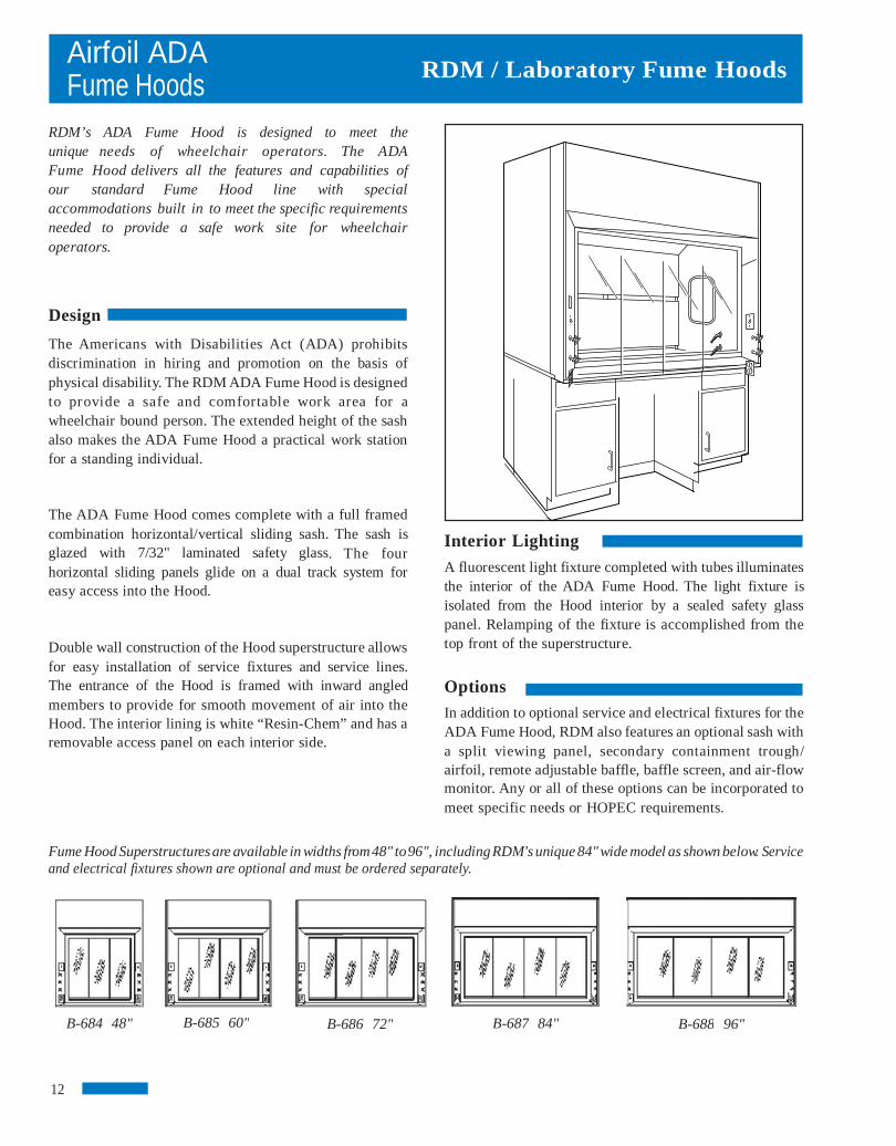
RDM’s ADA Fume Hood is designed to meet the unique needs of wheelchair operators. The ADA Fume Hood delivers all the features and capabilities of our standard Fume Hood line with special accommodations built in to meet the specific requirements needed to provide a safe work site for wheelchair operators. Design
The Americans with Disabilities Act (ADA) prohibits discrimination in hiring and promotion on the basis of physical disability. The RDM ADA Fume Hood is designed to provide a safe and comfortable work area for a wheelchair bound person. The extended height of the sash also makes the ADA Fume Hood a practical work station for a standing individual.
The ADA Fume Hood comes complete with a full framed combination horizontal/vertical sliding sash. The sash is glazed with 7/32" laminated safety glass. The four horizontal sliding panels glide on a dual track system for easy access into the Hood.
Double wall construction of the Hood superstructure allows for easy installation of service fixtures and service lines. The entrance of the Hood is framed with inward angled members to provide for smooth movement of air into the Hood. The interior lining is white “Resin-Chem” and has a removable access panel on each interior side.
Fume Hood Superstructures are available in widths from 48" to 96", including RDM's unique 84" wide model as shown below. Service and electrical fixtures shown are optional and must be ordered separately.
B-684 48" 12
B-688 96" B-686 72" B-685 60" B-687 84"
RDM / Laboratory Fume Hoods
Interior Lighting A fluorescent light fixture completed with tubes illuminatesthe interior of the ADA Fume Hood. The light fixture is isolated from the Hood interior by a sealed safety glass panel. Relamping of the fixture is accomplished from thetop front of the superstructure.
Options In addition to optional service and electrical fixtures for theADA Fume Hood, RDM also features an optional sash witha split viewing panel, secondary containment trough/ airfoil, remote adjustable baffle, baffle screen, and air-flowmonitor. Any or all of these options can be incorporated tomeet specific needs or HOPEC requirements.

Airfoil ADA Assemblies
The standard airfoil ADA Fume Hoods are each available as a complete assembly.
Detailed information on base cabinets, countertops and service fixtures is shown on pages 26, 28 and 29.
Each assembly includes two standard base cabinets (one on 48" assembly), knee space area, two LF35-7 filler
B-9870 84" B-9880 96"
75 FPM 100 FPM 125 FPM 150 FPM
CFM S.P. CFM S.P. CFM S.P. CFM S.P.
325 .05 433 .10 542 .15 650 .22
425 .05 567 .09 708 .15 850 .21
525 .05 700 .09 875 .15 1050 .21
625 .05 833 .09 1042 .14 1250 .21
725 .06 967 .11 1208 .18 1450 .25
The static pressures listed above are for the hoods only. An appropriate amount will have to be added to this figure to compensate for the pressure drop through the duct system. The total pressure drop through the hood and the duct system must be known to select the proper exhaust blower.
The CFM and static pressures listed above are measures with 50% of the sash area open.
36"
26 1/2"
Duct collar locations are as shown above. The center line of each collar is 8" from the back of the hood. The area indicated by the dashed lines is designated for plumbing and electri-cal rough-ins. All rough-ins should be kept within 7" of the wall and 18" from the floor.
13
RDM / Laboratory Fume Hoods
panels, dished epoxy resin countertop, F-400 3" x 6" epoxyresin cup sink, three F-100 service fixtures, F-110 cold water fixtures, F-200 light switch, F-210 blower switchand two F-220 110V duplexes.
All service and electrical fixtures are furnished, but not installed.
B-9860 72" HOOD COLLAR SIZE SIZE
48" 6" x 12"
60" 6" x 16"
72" 6" x 20"
84" (2)6" x 12"
96" (2)6" x 12"
26 1/2"
30"
23 1/2"
24"
23 1/2"
B-688
B-685
B-684
B-687
B-686
B-9840 48" B-9850 60"
Rough-in Details
33 7/8"
8"
7" 1" 22"
30"

Airfoil Radio Isotope Fume Hoods
Stainless steel lining and work surface with coved corners that facilitate thorough cleaning and a reinforced countertop to support lead bricks, are some of the features incorpo-rated into the Radio Isotope Hood. These features will help to insure operator safety and convenience in procedures that involve the use and handling of radioactive materials.
Design
The Radio Isotope Hood comes equipped with a type 304 stainless steel sash frame with a full width flush pull and is glazed with 7/32" thick laminated safety glass. A counterweight provides for one finger operation of the sash at any position. A lower stainless steel airfoil acts as a sash stop to maintain a 1" space, below the closed sash, which allows air to continuously flow across the work surface.
The interior lining of the Radio Isotope Fume Hood is type 304 stainless steel. All seams are welded and ground smooth to eliminate the build-up of radioactive materials. The work surface, which is constructed of the same materials, is welded to the lining, making the liner and work surface integral and water tight. In addition, the work surface is reinforced to support 200 lbs. per square foot up to a total weight of 1,000 lbs. per Hood or base cabinet section.
Double wall construction of the Hood superstructure allows space for installation of service fixtures. Access for installation and maintenance is acquired through the removable stainless steel interior access panel or by removing the exterior side panel of the superstructure. A built-in bypass feature above the Hood sash works to maintain a relatively constant face velocity at any sash position. Fume Hood Superstructures are available in widths from 48" to 96", including RDM's unique 84" wide model as shown below. Service and electrical fixtures shown are optional and must be ordered separately.
B-635 60" B-636 72" B-637 84" B-638 96"
RDM / Laboratory Fume Hoods
Interior Lighting The interior of the Radio Isotope Fume Hood is brightly lit by a maximum width dual fluorescent light fixture. The fixture is mounted behind a sealed safety glass panel to isolate thefixture from corrosive fumes and flammable vapors. Replacement of fluorescent tubes is accomplished from theexterior top front of the Fume Hood superstructure.
Options Optional service and electrical fixtures are available for installation in the Radio Isotope Fume Hood. Mountingholes are provided in the superstructure for on-site installation of the required service fixtures.
B-634 48" 14

Airfoil Radio Isotope Assemblies
Airfoil Radio Isotope Assemblies The five standard Fume Hood sizes are each available as a complete assembly.
Detailed information on base cabinets, countertops and service fixtures is shown on pages 26, 28 and 29.
The assembly for the 48" and 60" wide Hoods consists of a standard base cabinet, two LF35-7 filler panels, 3" x 6"
B-9340 48" B-9350 60" B-9360 72"
HOOD COLLAR SIZE SIZE
48" 6" x 12" 60" 6" x 16" 72" 6" x 20" 84" (2)6" x 12" 96" (2)6" x 12"
The static pressures listed above are for the hoods only. An appropriate amount will have to be added to this figure to compensate for the pressure drop through the duct system. The total pressure drop through the hood and the duct system must be known to select the proper exhaust blower.
24"
23 1/2"
1" Duct collar locations are as shown above. The center line of each collar is 8" from the back of the hood. The area indicated by the dashed lines is designated for plumbing and electrical rough-ins. All rough-ins should be kept within 7" of the wall and 18" from the floor.
15
RDM / Laboratory Fume Hoods
stainless steel cup sink, six F-100 service fixtures, F-110 cold water fixture, F-200 light switch, F-210 blowerswitch and two F-220 110V duplexes.
72", 84" and 96" assemblies include all of the above alongwith a second base cabinet, cup sink and water fixture.
All service and electrical fixtures are furnished, but not installed.
B-9370 84" B-9380
75 FPM 100 FPM 125 FPM
CFM S.P. CFM S.P. CFM S.P.
650 .22 867 .39 1083 .61 850 .21 1133 .38 1417 .59
1050 .21 1400 .37 1750 .58 1250 .21 1667 .37 2083 .58 1450 .25 1933 .45 2417 .71
96"
150 FPM
CFM S.P. 1300 .87 1700 .85 2100 .84 2500 .83 2900 1.02
26 1/2"
36"
26 1/2"
30"
23 1/2"
B-637
B-634
B-635
B-638
B-636
Rough-in Details
33 7/8"
8"
7" 22"
30"

Airfoil Perchloric Acid Fume Hoods
This Fume Hood is specifically designed for the use of perchloric acid. A coved stainless steel liner with integral work surface, an internal water wash down system and water collection trough provide for detailed cleaning of the Hood interior. In addition, the interior baffles are also removable for cleaning to prevent the dangerous build-up of perchlorates.
Design
The Perchloric Acid Fume Hood has an internal bypass located above the sash. The bypass operates automatically, opening when the sash is closed and closing as the sash is raised. The bypass provides for a relatively constant face velocity at any sash position. The sash frame and lower airfoil are constructed of type 316 stainless steel. The sash is glazed with 7/32" thick laminated safety glass and has full width pull and counterweight for easy up/down operation. In the closed position, the lower airfoil acts as a sash stop providing a 1" space for air to continuously sweep the work surfaces. The interior liner, work surface and baffles are also con-structed of type 316 stainless steel. A wash down spray bar is located behind the upper baffle for continuous cleaning behind the baffles. A full width trough is located below the lower baffle to collect the wash down water from both the Hood and ductwork. Double wall construction of the superstructure allows for installation of service fixtures and routing of interior plumbing and electrical lines. Access for installation and maintenance of service fixtures is obtained by removing the exterior side panel.
Fume Hood Superstructures are available in widths from 48" to 96", including RDM's unique 84" wide model as shown below. Service and electrical fixtures shown are optional and must be ordered separately.
B-646 72" B-647 84" B-648 96"B-644 48"
16
B-645 60"
RDM / Laboratory Fume Hoods
Interior Lighting A two tube fluorescent light fixture illuminates the interior ofthe Perchloric Acid Fume Hood. The fixture is mounted behind asealed safety glass panel to isolate the fixture from corrosivefumes and flammable vapors. Replacement of fluorescent tubesis accomplished from the exterior top front of the Fume Hoodsuperstructure.
Options A variety of optional service fixtures are available from RDM.The location of the fixtures must be specified for accurate cutting of the mounting holes located in the Fume Hood lining.

Airfoil Perchloric Acid Assemblies
Airfoil Perchloric Acid Assemblies The five standard Fume Hood sizes are each available as a complete assembly.
Detailed information on base cabinets, countertops and service fixtures is shown on pages 26, 28 and 29.
The assembly for the 48" and 60" wide Hoods consists of a standard base cabinet, two LF35-7 filler panels, 3" x 6"
B-9440 48" B-9450 60" B-9460 72" B-9470 84" B-9480 96"
Rough-in Details
The static pressures listed above are for the hoods only. An appropriate amount will have to be added to this figure to compensate for the pressure drop through the duct system. The total pressure drop through the hood and the duct system must be known to select the proper exhaust blower.
36"
26 1/2"
Duct collar locations are as shown above. The center line of each collar is 8" from the back of the hood. The area indicated by the dashed lines is designated for plumbing and electrical rough-ins. All rough-ins should be kept within 7" of the wall and 18" from the floor.
17
RDM / Laboratory Fume Hoods
stainless steel cup sink, six F-100 service fixtures, F-110 cold water fixture, F-200 light switch, F-210 blowerswitch and two F-220 110V duplexes.
72", 84" and 96" assemblies include all of the above alongwith a second base cabinet, cup sink and water fixture.
All service and electrical fixtures are furnished, but not installed.
26 1/2"
24"
23 1/2"
30"
23 1/2"
B-648
B-645
B-644
B-647
B-646
HOOD SIZE
COLLAR SIZE
75 FPM 100 FPM 125 FPM 150 FPM
CFM S.P. CFM S.P. CFM S.P. CFM S.P. 48" 6" x 12" 650 .22 867 .39 1083 .61 1300 .87 60" 6" x 16" 850 .21 1133 .38 1417 .59 1700 .85 72" 6" x 20" 1050 .21 1400 .37 1750 .58 2100 .84 84" (2)6" x 12" 1250 .21 1667 .37 2083 .58 2500 .83 96" (2)6" x 12" 1450 .25 1933 .45 2417 .71 2900 1.02
WB-MAX Airfoil Low Bench & Walk-In Fume Hoods
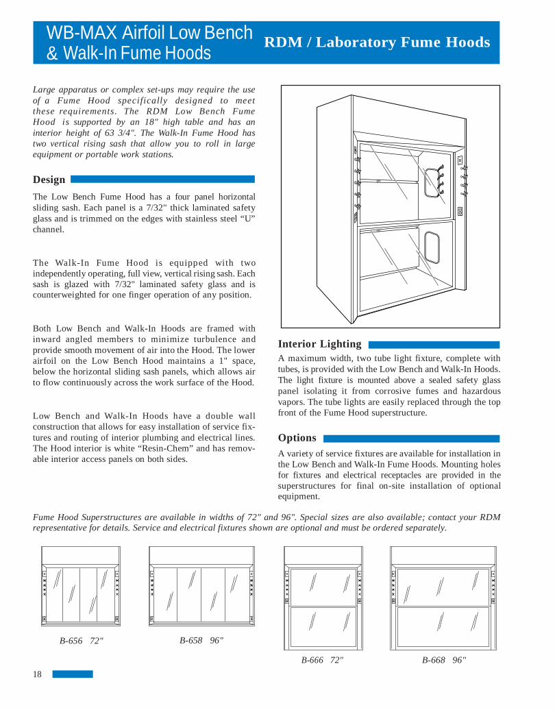
Large apparatus or complex set-ups may require the use of a Fume Hood specifically designed to meet these requirements. The RDM Low Bench Fume Hood is supported by an 18" high table and has an interior height of 63 3/4". The Walk-In Fume Hood has two vertical rising sash that allow you to roll in large equipment or portable work stations.
Design
The Low Bench Fume Hood has a four panel horizontal sliding sash. Each panel is a 7/32" thick laminated safety glass and is trimmed on the edges with stainless steel “U” channel. The Walk-In Fume Hood is equipped with two independently operating, full view, vertical rising sash. Each sash is glazed with 7/32" laminated safety glass and is counterweighted for one finger operation of any position. Both Low Bench and Walk-In Hoods are framed with inward angled members to minimize turbulence and provide smooth movement of air into the Hood. The lower airfoil on the Low Bench Hood maintains a 1" space, below the horizontal sliding sash panels, which allows air to flow continuously across the work surface of the Hood. Low Bench and Walk-In Hoods have a double wall construction that allows for easy installation of service fix-tures and routing of interior plumbing and electrical lines. The Hood interior is white “Resin-Chem” and has remov-able interior access panels on both sides.
Fume Hood Superstructures are available in widths of 72" and 96". Special sizes are also available; contact your RDM representative for details. Service and electrical fixtures shown are optional and must be ordered separately.
B-658 96"
B-666 72" B-668 96"
RDM / Laboratory Fume Hoods
Interior Lighting A maximum width, two tube light fixture, complete withtubes, is provided with the Low Bench and Walk-In Hoods.The light fixture is mounted above a sealed safety glass panel isolating it from corrosive fumes and hazardous vapors. The tube lights are easily replaced through the topfront of the Fume Hood superstructure.
Options A variety of service fixtures are available for installation inthe Low Bench and Walk-In Fume Hoods. Mounting holesfor fixtures and electrical receptacles are provided in the superstructures for final on-site installation of optional equipment.
B-656 72"
18
WB-MAX Airfoil Low Bench & Walk-In Assemblies
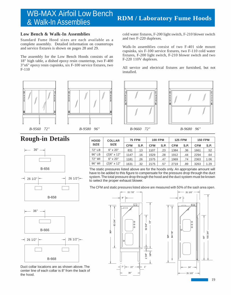
Low Bench & Walk-In Assemblies Standard Fume Hood sizes are each available as a complete assembly. Detailed information on countertops and service fixtures is shown on pages 28 and 29.
The assembly for the Low Bench Hoods consists of an 18" high table, a dished epoxy resin countertop, two F-400 3"x6" epoxy resin cupsinks, six F-100 service fixtures, two F-110
B-9560 72" B-9580 96" B-9660 72" B-9680 96"
Rough-in Details
36"
The static pressures listed above are for the hoods only. An appropriate amount will have to be added to this figure to compensate for the pressure drop through the duct system. The total pressure drop through the hood and the duct system must be known to select the proper exhaust blower.
The CFM and static pressures listed above are measured with 50% of the sash area open.
Duct collar locations are as shown above. The center line of each collar is 8" from the back of the hood.
RDM / Laboratory Fume Hoods
cold water fixtures, F-200 light switch, F-210 blower switchand two F-220 duplexes.
Walk-In assemblies consist of two F-401 side mount cupsinks, six F-100 service fixtures, two F-110 cold waterfixtures, F-200 light switch, F-210 blower switch and twoF-220 110V duplexes.
All service and electrical fixtures are furnished, but not installed.
26 1/2"
26 1/2"
26 1/2"
36"
26 1/2"
B-656
B-658
B-668
B-666
8"
7" 1"
33 7/8"
22"
30"
HOOD SIZE
COLLAR SIZE
75 FPM 100 FPM 125 FPM 150 FPM
CFM S.P. CFM S.P. CFM S.P. CFM S.P. 72" LB 6" x 20" 831 .13 1107 .23 1384 .36 1661 .52 96" LB (2)6" x 12" 1147 .16 1529 .28 1912 .44 2294 .64 72" WI 6" x 20" 1181 .26 1575 .47 1969 .74 2363 1.06 96" WI (2)6" x 12" 1631 .32 2175 .57 2719 .89 3263 1.29
35 3/8"
8"
24"
35 3/8"
19

XB-MAX Thin Wall Fume Hoods
The RDM Thin Wall Fume Hood provides an excellent low cost means of exhausting high heat loads and non-hazardous fumes.
The Thin Wall design allows for maximum interior work area and is well suited for installation on any counter of 30" depth.
Design
The exterior of the Thin Wall Fume Hood is 18 gauge steel with an epoxy powder coat finish, front posts are stainless steel with a #4 finish. These components are attached to a heavy gauge internal framework. This framework is welded and bolted together to provide a rigid durable structure for the Thin Wall Hood.
The interior of the Hood is lined with Minerit, a chemical resistant gray composition stone material. The liner is attached to the internal framework with the use of non-metallic fasteners. A lintel, of the same material, restricts the air intake of the Hood to the sash opening. This restriction allows you to vary the face velocity of the Thin Wall Fume Hood by changing the sash position. An interior baffle system, also constructed of minerit, maintains a uniform face velocity across the entire opening of the sash. The upper portion of the baffle is adjustable to compensate for high heat loads or light fumes.
The full view sash of the Thin Wall Hood is framed with a chemical resistant black PVC. It is glazed with 7/32" thick laminated safety glass and has a single counterweight for easy up/down operations.
Fume Hood Superstructures are available in widths from 48" to 96", including RDM's unique 84" wide model as shown below. Service and electrical fixtures shown are optional and must be ordered separately.
B-834 48" B-835 60" B-836 72" B-837 84" B-838 96" B-833 36” 20
RDM / Laboratory Fume Hoods
Interior Lighting The interior of the Thin Wall Fume Hood is brightly lit by avapor proof incandescent light fixture, bulb included. A single light fixture is provided in 48", 60" and 72" models and two fixtures are provided in the other models.Replacement of the incandescent bulbs is accomplished from the interior of the Hood.
Options Switches, outlets, and remote valves must be located on thefront panel of the Fume Hood base cabinet. Refer to pages28 and 29 for details.

RDM / Laboratory Fume Hoods
consist of a standard base cabinet, two LF35-7 filler panels, a 1" thick black epoxy resin countertop, F-200 light switch, F-210 blower switch and two F-220 110V duplexes.
72", 84" and 96" assemblies include all of the above along with a second base cabinet. Electrical fixtures are furnished but not installed.
B-9740 48" B-9750 60" B-9760 72" B-9770 84" B-9780 96"
Rough-in Details
The static pressures listed above are for pressure drop through the hoods only. An appropriate amount will have to be added to this figure to compensate for the pres-sure drop through the duct system. The total pressure drop through the hood and the duct system must be known to select the proper exhaust blower.
Duct collar locations are as shown above. The center line of each collar is 8" from the back of the hood. The area indicated by the dashed lines is designated for plumbing and electrical rough-ins. All rough-ins should be kept within 7" of the wall and 18" from the floor.
21
XB-MAX Thin Wall Assemblies
Thin Wall Fume Hood Assemblies The five standard Fume Hood sizes are each available as acomplete assembly.
Detailed information on base cabinets and service fixturesis shown on pages 26, 28 and 29.
Assemblies for 48" and 60" wide Fume Hoods
HOOD SIZE
COLLAR SIZE
75 FPM 100 FPM 125 FPM 150 FPM
CFM S.P. CFM S.P. CFM S.P. CFM S.P. 48" 9" DIA. 710 .29 947 .51 1184 .80 1421 1.16 60" 10" DIA. 904 .30 1206 .54 1507 .84 1808 1.21 72" 10" DIA. 1098 .41 1464 .72 1830 1.13 2196 1.63 84" (2) 9" DIA. 1292 .25 1722 .45 2153 .70 2583 1.01 96" (2) 9" DIA. 1485 .31 1981 .55 2476 .86 2971 1.24

Demonstration Fume Hoods
The RDM Demonstration Fume Hoods feature dual access sashes and offer a clear, unobstructed view of the Hood interior.
Design Two independently operating sashes provide viewing and access from either side of the Demonstration Fume Hood. A fixed end window is also provided to increase the interior viewing.
Sashes are glazed with laminated safety glass and have a full width PVC pull for maximum chemical resistance. The Hood interior is lined with chemical resistant “Resin-Chem” and is illuminated with a vapor proof incandescent light fixture.
Options Two 3-way switches, a blower switch and two duplex outlets are available for installation on the Demonstration Hood. These items are optional and must be ordered separately.
Rough-in Details
The static pressures listed above are for pressure drop through the hoods only. An appro-priate amount will have to be added to this figure to compensate for the pressure drop through the duct system. The total pressure drop through the hood and the duct system must be known to select the proper exhaust blower.
The CFM and static pressures listed above are measured with one sash open.
48" or
60"
22
RDM / Laboratory Fume Hoods
MODEL NUMBER
SIZE
COLLAR SIZE
75 FPM 100 FPM 125 FPM 150 FPM
CFM S.P. CFM S.P. CFM S.P. CFM S.P. B-814 48" 6" x 16" 569 .20 758 .36 948 .56 1137 .80 B-816 60" 6" x 16" 744 .34 992 .61 1240 .96 1488 1.38

Portable Fume Hood
The RDM Portable Fume Hood features safety and convenience. Mobile design allows the Portable Fume Hood to be wheeled into a working position and moved back to a storage location when the task is complete. Clear view side and back panels make the Portable Fume Hood ideally suited for demonstrations. It also allows instructor observation when being used as a student work station.
Design
The framework of the Portable Fume Hood is fully welded, painted square tubing. The upper metal housing contains a single tube fluorescent light (bulb included), exhaust fan, light and fan switches, duplex outlet and a double sided gas hose connector. The interior work surface is black epoxy resin and is enclosed with 1/4" Plexiglas viewing panels. The front viewing panel is hinged for easy access. Additional features include locking swivel casters, six foot long power cord and six feet of 1 1/2" diameter flexible exhaust duct.
The amount of air being exhausted through the hood will vary depending on the length and shape of the ductwork. The chart below shows the exhaust volume (CFM) at various static pressures. For installations requiring long runs of ductwork, a supple-mental exhaust system may be required.
Exhaust fan is 115 V, 60 CY, 2870 RPM
23
RDM / Laboratory Fume Hoods
B-1735-PH - Hood B-1735-PT - Countertop B-1735-PS - Mobile Stand
Rough-in Details
MODEL NUMBER
COLLAR SIZE
CFM AT STATIC PRESSURE SHOWN
S.P. CFM S.P. CFM S.P. CFM S.P. CFM S.P. CFM S.P. CFM
B-1735-PH 1 1/2" DIA. FREE AIR
100 .1 98 .2 95 .3 90 .4 85 .5 80

Spray Booth
The RDM Spray Booth offers an economical way to exhaust odors and non-toxic fumes in Laboratory, Class Room and Shop environments.
Design
The RDM Spray Booth is constructed of 18 gauge steel that is formed and welded into a rigid superstructure. Each unit is finished with a chemical resistant powder coat paint fin-ish and has a replaceable, pleated air filter. The Spray Booth is designed to have a non-explosion proof exhaust blower (specified on the next page) mounted directly on top of the unit. A rectangular duct transition is included to connect the exhaust blower to the Spray Booth. For flammable fumes or vapors, an optional explosion proof exhaust blower must be specified. The explosion proof exhaust blower is designed to be mounted on the roof or other suitable location, but not on top of the Spray Booth.
Interior Lighting The interior of the Spray Booth is illuminated by a vapor proof incandescent light fixture (bulb included). Light bulb replacement is accomplished from the interior of the booth. When exhausting flammable fumes or vapors, an optional explosion proof light fixture must be specified.
Spray Booth Superstructures are available in widths from 24" to 48" as shown below.
B-811 30" B-812 36" B-813 48"B-810 24"
24
RDM / Laboratory Fume Hoods
Options Optional service and electrical fixtures are available for use withthe RDM Spray Booth. Contact your RDM representativeto assist you in specifying these items.

RDM / Laboratory Fume Hoods
Motors are 115V/60HZ with H.P. as shown above.
Contact your RDM representative to assist you in specifying an explosion proof exhaust blower.
Spray Booth replacement filters are a 1" thick cotton polyester blended filter, laminated to a galvanized steel expanded metal support grid. Order by part number from the chart to the left. (Note: 36" and 48" Spray Booths require two filters.)
Rough-in Details
B
A
C
5" x 10 7/8"
Plan View of Spray Booth
Top Without Blower
Spray Booth Exhaust Blowers Exhaust Blowers feature a dynamically balanced forwardcurve wheel with cast iron hubs. Housing and motor base are 16 gauge steel with a gray baked-on epoxyfinish.
Replacement Filters
D
See Blower Outlet Size Above
Plan View of Spray Booth Top With Blower
25
HOOD SIZE
DIMENSIONS
“A” “C” “B” “D” “E” 24" 7" 4 3/4" 10 7/16" 10 3/8" 6"
30" 7" 7 3/4" 8" 14" 6"
36" 7" 10 3/4" 10 7/8" 17 5/8" 6 7/8"
48" 7" 19 3/4" 10 7/8" 26 5/8" 6 7/8"
HOOD SIZE
FILTER NUMBER
QUANTITY
SIZE
24" 6556 1 16"X20"
30" 6557 1 22"X20"
36" 6558 2 14"X20"
48" 6559 2 20"X20"
HOOD SIZE
MODEL NUMBER
OUTLET SIZE
HP
CFM AT STATIC PRESSURE SHOWN
.125 .25 .375 .5 .625 .75
24" 7C037 4 1/4" x 7 3/8" 1/4 560 515 470 420 360 300
30" 7C038 5 3/8" x 8 1/4" 1/3 920 870 820 765 710 655
36" 7C039 6 1/2" x 10 3/4" 1/3 968 930 890 850 810 773
48" 7C647 6 1/2" x 10 3/4" 1/3 1160 1125 1090 1035 963 855
Canopy Hoods & Base Cabinets
Canopy Hoods C
* Threaded Rods NOT included
50 FPM
CFM S.P.
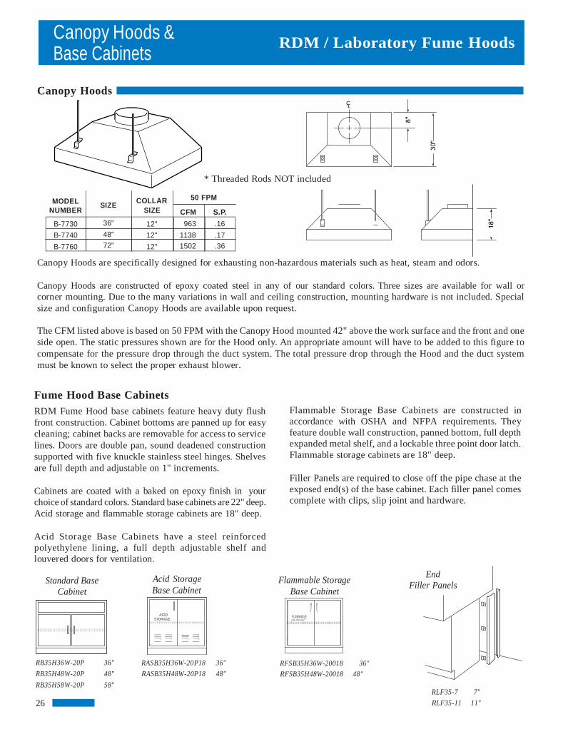
Canopy Hoods are specifically designed for exhausting non-hazardous materials such as heat, steam and odors.
Canopy Hoods are constructed of epoxy coated steel in any of our standard colors. Three sizes are available for wall or corner mounting. Due to the many variations in wall and ceiling construction, mounting hardware is not included. Special size and configuration Canopy Hoods are available upon request.
The CFM listed above is based on 50 FPM with the Canopy Hood mounted 42" above the work surface and the front and one side open. The static pressures shown are for the Hood only. An appropriate amount will have to be added to this figure to compensate for the pressure drop through the duct system. The total pressure drop through the Hood and the duct system must be known to select the proper exhaust blower.
Fume Hood Base Cabinets RDM Fume Hood base cabinets feature heavy duty flush front construction. Cabinet bottoms are panned up for easy cleaning; cabinet backs are removable for access to service lines. Doors are double pan, sound deadened construction supported with five knuckle stainless steel hinges. Shelves are full depth and adjustable on 1" increments. Cabinets are coated with a baked on epoxy finish in your choice of standard colors. Standard base cabinets are 22" deep. Acid storage and flammable storage cabinets are 18" deep. Acid Storage Base Cabinets have a steel reinforced polyethylene lining, a full depth adjustable shelf and louvered doors for ventilation.
Acid Storage Base Cabinet
ACID
STORAGE
RASB35H36W-20P18 36"
RASB35H48W-20P18 48"
L
MODEL NUMBER
SIZE COLLAR
SIZE
Flammable Storage Base Cabinets are constructed in accordance with OSHA and NFPA requirements. Theyfeature double wall construction, panned bottom, full depthexpanded metal shelf, and a lockable three point door latch.Flammable storage cabinets are 18" deep. Filler Panels are required to close off the pipe chase at theexposed end(s) of the base cabinet. Each filler panel comescomplete with clips, slip joint and hardware.
RFSB35H36W-20018 36"
RFSB35H48W-20018 48"
RLF35-7 7"
RLF35-11 11"
End Filler Panels Flammable Storage
Base Cabinet Standard Base
Cabinet
RB35H36W-20P 36"
RB35H48W-20P 48"
RB35H58W-20P 58"
26
F LAM M ABLE
KEEP FIRE AWAY
B-7730
B-7740
B-7760
36"
48"
72"
12"
12"
12"
963
1138
1502
.16
.17
.36
RDM / Laboratory Fume Hoods
Sash Options and Ceiling Enclosures
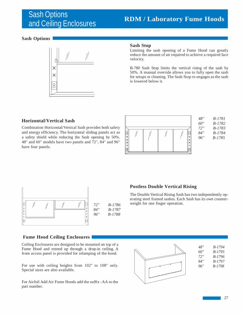
Sash Options Horizontal/Vertical Sash Combination Horizontal/Vertical Sash provides both safety and energy efficiency. The horizontal sliding panels act as a safety shield while reducing the Sash opening by 50%. 48" and 60" models have two panels and 72", 84" and 96" have four panels.
72" B-1786 84" B-1787 96" B-1788
Fume Hood Ceiling Enclosures
Ceiling Enclosures are designed to be mounted on top of a Fume Hood and extend up through a drop-in ceiling. A front access panel is provided for relamping of the hood.
For use with ceiling heights from 102" to 108" only. Special sizes are also available.
For Airfoil Add Air Fume Hoods add the suffix -AA to the part number.
27
RDM / Laboratory Fume Hoods
Sash Stop Limiting the sash opening of a Fume Hood can greatly reduce the amount of air required to achieve a required facevelocity.
B-780 Sash Stop limits the vertical rising of the sash by 50%. A manual override allows you to fully open the sashfor setups or cleaning. The Sash Stop re-engages as the sashis lowered below it.
48" B-1781 60" B-1782 72" B-1783 84" B-1784 96" B-1785
Postless Double Vertical Rising
The Double Vertical Rising Sash has two independently op-erating steel framed sashes. Each Sash has its own counter-weight for one finger operation.
48" B-1794 60" B-1795 72" B-1796 84" B-1797 96" B-1798

Service Fixtures and Alarms
Remote Control Fume Hood Fixtures
Remote control valves have forged brass valve bodies for strength and durability. Valves for gas, air, vacuum and special gases are of needle type design with a stainless steel floating cone and stainless steel replaceable seat. Valves for steam service have a flat Teflon valve disc and stainless steel replaceable seat; valves for water service have a renewable unit including a stainless steel seat and volume control. All outlet assemblies are furnished with a polished chrome plated finish. For acid and solvent resistant coatings add the following suffix to part numbers.
Clear Epoxy 01 White Epoxy 02 Black Epoxy 03 Sepia Bronze 04 Metallic Aluminum 05
For factory setting of a service fixture, specify part number F-330 in addition to the service fixture number. For factory setting and piping of service fixtures, specify part number F-300 in addi tion to the ser vice fixture number.
F-100 - Remote service valve with angled hose cock outlet. For use with gas, air, vacuum, steam or other special gases. Specify type of service.
F-110 - Remote service valve with gooseneck, for use with water; specify hot or cold water.
F-120 - Remote service valve with gooseneck and vacuum breaker, for use with water; specify hot or cold water.
F-125 - Dual remote service valve with gooseneck, for use with hot and cold water.
F-130 - Dual remote service valve with gooseneck and vacuum breaker, for use with hot and cold water.
Air Velocity Monitor & Alarm
F-278 Velocity Monitor measures the face velocity of the Fume Hood. The monitor includes a visual safe indicator light, visual alarm indicator light, audible alarm and a test reset button which also manually silences the alarm. Field calibration requires the use of an optional air flow measuring device as shown on page 32.
RDM / Laboratory Fume Hoods
F-100
F-110
F-120
F-125
F-130
R D M N a t i o n a l P r o d u c t s
F-278
28
TEST-R ESET

Electrical Fixtures and Countertops
Electrical Services Flush mount electrical service fixtures come complete with device box and stainless steel face plate. Explosion proof fixtures meet Class 1, Group C & D requirements. Explosion proof outlets and switches must be mounted on the front panel of the base cabinet or the exterior side of the Fume Hood. For factory setting of electrical fixtures, specify part number F-340 in addition to the electrical fixture number. For factory setting and wiring of electrical fixtures, specify part number F320 in addit ion to the electr ical fixture number. Factory wiring of explosion proof fixtures on application only.
F-225 F-200 - Single pole light switch, 115 volt, 15 amp. F-210 - Manual motor starter switch with pilot light, 115 volt, 15 amp. Heating element not included. F-220 - Duplex receptacle, 115 volt, 15 amp. F-221 - Duplex receptacle, 115 volt, 20 amp. F-225 - GFI duplex receptacle, 115 volt, 15 amp. F-260 - Explosion proof light fixture, specify two fixtures on hoods 84" and over. F-262 - Explosion proof receptacle. F-264 - Explosion proof switch.
F-264
Countertops
Fume Hood work surfaces are molded from a modified epoxy resin that has been especially compounded and cured to provide optimum physical and chemical resistance required for a heavy duty laboratory working surface. Countertops are 1" thick with a 3/8" deep dishing to contain spills and have a non-glaring black finish.
If sinks or cupsinks are required, specify location.
29
RDM / Laboratory Fume Hoods
F-200 F-210
F-220 F-221
F-260
F-262
B-8040 48" B-8050 60" B-8060 72" B-8070 84" B-8080 96"
Front

RDM / Laboratory Fume Hoods
Sinks Sinks are available in a variety of sizes and configurations for installation in Fume Hoods.
F-400 - Oval epoxy resin cup sink, 3"x6", 1 1/2" NPT outlet connection.
F-401 - Oval polypropylene panel mount cup sink, 3"x6", with retainer nut, 1 1/2" NPT outlet connection. F-400
F-402 - Rectangular epoxy resin cup sink, 13 3/4" x 4 1/2" x 5 1/2" with stainless steel straining screen, 1 1/2" NPT outlet.
F-410 - Drop-in epoxy resin sink, 16" x 12" x 8" Dp.
F-402 F-411 - Drop-in epoxy resin sink, 18" x 15" x 8" Dp. F-412 - Drop-in epoxy resin sink, 24" x 16" x 8" Dp.
F-410 F-411 F-412
Drains and Traps F-420 - Epoxy resin sink outlet with retainer nut, 1 1/2" NPT outlet connection. F-425 - Polypropylene p-trap with adjustable riser, 1 1/2" NPT outlet connection.
F-425
Baths
Baths are available in steam, hot water or electric. Each bath is furnished with four sets of concentric rings which are spaced on 1" increments up to 6" diameter. Baths are constructed of 20 gauge, type 304 stainless steel and come complete with a remote valve for mounting in the post of the Fume Hood. Size is 18" x 18".
F-430 Steam F-431 Hot Water F-432 Electric
Baths
30
Sinks, Drainsand Baths
F-420

RDM / Laboratory Fume Hoods
Fire Extinguishers F-439 Automatic Fire Extinguisher units are available for in-stallation in Fume Hoods. Fire Extinguishers are activated by a fusible link. The link melts at 165º F, opening the valve which released a multipurpose ABC Dry Chemical. Cylinders are con-structed of stainless steel and come complete with mounting bracket. Fume Hoods 72" and wider require the use of two Fire Extinguishers for adequate projection.
F-439
Vent Kits F-440 Vent Kits are used to vent acid or flammable storage cabinets to the Fume Hood.
F-440 Baffle Options
Standard Fume Hoods are equipped with an adjustable upper baffle only. Other adjustable baffle options are available as follows:
B-790 Lower Adjustable Baffle B-791 Single Point Remote Adjustable Baffle for 48", 60" and 72" Hoods B-792 Single Point Remote Adjustable Baffle for 84" and 96" Hoods
Material Options
The design of the RDM Fume Hoods allows for easy substitution of standard components with optional materials. Interior linings are available in minerit, PVC or stainless steel in lieu of our standard Resin-Chem. Sash options include full framed, painted or stainless steel sash. Sash tracks and lower airfoils are both available in stainless steel. Contact your RDM representative to assist you in specifying these items.
31
Accessories and Options
RDM / Laboratory Fume Hoods
Lattice Assemblies
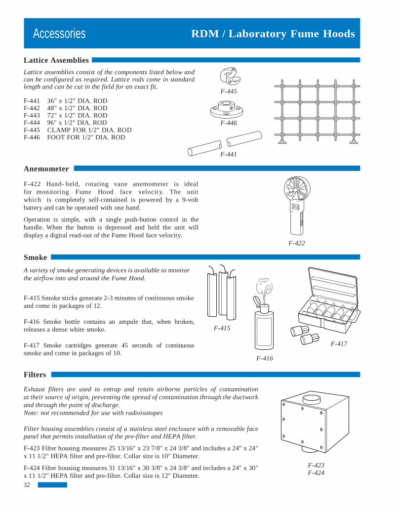
Lattice assemblies consist of the components listed below and can be configured as required. Lattice rods come in standard length and can be cut in the field for an exact fit.
F-441 36" x 1/2" DIA. ROD F-442 48" x 1/2" DIA. ROD F-443 72" x 1/2" DIA. ROD F-444 96" x 1/2" DIA. ROD F-445 CLAMP FOR 1/2" DIA. ROD F-446 FOOT FOR 1/2" DIA. ROD
F-441
Anemometer
F-422 Hand- held, rotating vane anemometer is ideal for monitoring Fume Hood face velocity. The unit which is completely self-contained is powered by a 9-volt battery and can be operated with one hand.
Operation is simple, with a single push-button control in the handle. When the button is depressed and held the unit will display a digital read-out of the Fume Hood face velocity.
F-422
Smoke
A variety of smoke generating devices is available to monitor the airflow into and around the Fume Hood.
F-415 Smoke sticks generate 2-3 minutes of continuous smoke and come in packages of 12. F-416 Smoke bottle contains an ampule that, when broken, releases a dense white smoke. F-417 Smoke cartridges generate 45 seconds of continuous smoke and come in packages of 10.
Filters
Exhaust filters are used to entrap and retain airborne particles of contamination at their source of origin, preventing the spread of contamination through the ductwork and through the point of discharge. Note: not recommended for use with radioisotopes Filter housing assemblies consist of a stainless steel enclosure with a removable face panel that permits installation of the pre-filter and HEPA filter.
F-423 Filter housing measures 25 13/16" x 23 7/8" x 24 3/8" and includes a 24" x 24" x 11 1/2" HEPA filter and pre-filter. Collar size is 10" Diameter.
F-424 Filter housing measures 31 13/16" x 30 3/8" x 24 3/8" and includes a 24" x 30" x 11 1/2" HEPA filter and pre-filter. Collar size is 12" Diameter. 32
F-445
F-446
F-415
F-416
F-417
F-423 F-424
Accessories

RDM / Laboratory Fume Hoods
Duct Transitions Duct Transitions are designed to convert the rectangular collar of the RDM Fume Hood to a round collar.
Transitions are constructed of heavy gauge coated steel and will work with standard round ductwork.
F-500 6"x12" Collar to 9" Dia. F-501 6"x12" Collar to 10" Dia. F-502 6"x14" Collar to 9" Dia. F-503 6"x16" Collar to 10" Dia. F-504 6"x20" Collar to 12" Dia.
Y Branches
Y Branches are used to connect two exhaust or supply ducts on Fume Hoods that require more than one exhaust or supply collar. Branches are constructed of coated steel and will work with standard round ductwork. F-506 (2) 9" Dia. to a Single 12" Dia. F-507 (2) 9" Dia. to a Single 14" Dia.
Y-Branches
Duct Wash Down
F-508 Wash Down assemblies are suited for use with perchloric acid duct systems. Each nozzle is capable of delivering 3 gallons of water per minute at a water pressure of 40 PSI. The Wash Down assembly is designed to be attached to 12" dia. duct and has a 1/4" male pipe connection.
F-508
Local Exhaust
F-509 The RDM Local Exhaust Hood is designed for use with atomic absorption spectrophotometers or flame photometer equipment. Unit comes complete with a 12" dia. stainless steel cone, 8' of 6" dia. flexible duct and adjustable support arm.
F-509 Blowers Blowers for both exhaust and supply are designed for efficient, quiet, continuous duty. Units have a forward curved impeller and come complete with a weatherproof drive cover. Spark resistant and corrosion resistant coatings are available upon request.
When using the chart on page 34, figure the equivalent of 15 linear feet of ductwork for each 90 degree elbow. For complex exhaust systems, contact your RDM representative for assistance in selecting a blower.
33
Accessories
Transitions
RDM / Laboratory Fume Hoods
*=PVC Construction **=Flanged Connection
BlowersBlowers
34
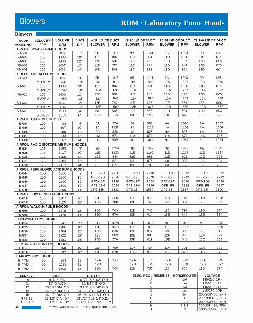
HOOD VELOCITY VOLUME DUCT 0-25 L/F OF DUCT 25-50 L/F OF DUCT 50-75 L/F OF DUCT 75-100 L/F OF DUCT MODEL NO. FPM CFM DIA BLOWER RPM BLOWER RPM BLOWER RPM BLOWER RPM AIRFOIL BYPASS FUME HOODS SB-604 100 867 9" 9B 1016 9B 1144 9C 1203 9D 1281 SB-605 100 1133 10" 11C 882 11D 981 11D 1026 11D 1071 SB-606 100 1400 12" 12C 686 12D 733 12D 822 12D 865 SB-607 100 1667 12" 12D 725 12D 747 12D 788 12D 829 SB-608 100 1933 14" 15D 565 15D 565 15D 603 15D 603 AIRFOIL ADD AIR FUME HOODS SB-624 100 867 9" 9B 1016 9B 1144 9C 1203 9D 1261
SUPPLY 607 9" 9A 813 9A 880 9A 897 9A 974 SB-625 100 1133 10" 11C 882 11D 981 11D 1026 11D 1071
SUPPLY 793 10" 11A 693 11A 750 11A 757 11A 822 SB-626 100 1400 12" 12C 686 12D 733 12D 822 12D 865
SUPPLY 980 12" 12A 545 12A 560 12A 608 12A 668 SB-627 100 1667 12" 12E 747 12E 788 12E 868 12E 906
SUPPLY 1167 12" 12B 580 12B 625 12B 650 12B 677 SB-628 100 1933 14" 15D 565 15D 565 15D 603 15D 603
SUPPLY 1353 14" 13C 575 13C 596 13C 640 13C 685 AIRFOIL ADA FUME HOODS
B-684 100 433 9" 8A 950 8A 985 8A 1020 8A 1055 B-685 100 567 10" 8A 1126 8A 1126 8A 1126 8A 1126 B-686 100 700 12" 9A 826 9A 826 9A 826 9A 826 B-687 100 833 12" 11A 674 11A 674 11A 674 11A 746 B-688 100 967 14" 9C 1064 9C 1064 9C 1064 9C 1064
AIRFOIL RADIO ISOTOPE AIR FUME HOODS B-634 125 1083 9" 9D 1296 9D 1349 9D 1449 9E 1543 B-635 125 1417 10" 11E 1155 11E 1195 11E 1267 11E 1337 B-636 125 1750 12" 12E 848 12E 886 12E 823 12E 923 B-637 125 2083 12" 13F 821 13F 876 13F 933 13F 990 B-638 125 2417 14" 15E 671 15E 703 15F 766 15F 766
AIRFOIL PERCHLORIC ACID FUME HOODS B-644 150 1300 9" GFE-12D 2200 GFE-12D 2200 GFE-12D 2382 GFE-12E 2382 B-645 150 1700 10" GFE-12D 2570 GFE-12E 2570 GFE-12F 2732 GFE-12F 2732 B-646 150 2100 12" GFE-12F 2728 GFE-12F 2886 GFE-12F 2886 GFE-12G 2886 B-647 150 2500 12" GFE-15H 2259 GFE-15H 2396 GFE-15I 2522 GFE-15I 2637 B-648 150 2900 14" GFE-15H 2431 GFE-15I 2557 GFE-15I 2557 GFE-15I 2600
AIRFOIL LOW BENCH FUME HOODS B-656 100 1107 10" 11C 880 11D 979 11D 1020 11D 1068 B-658 100 1529 12" 12D 700 12D 769 12D 851 12E 900
AIRFOIL WALK-IN FUME HOODS B-666 100 1575 12" 12C 705 12D 740 12D 794 12D 877 B-668 100 2175 14" 15D 570 12D 614 15E 649 15E 680
THIN WALL FUME HOODS B-834 100 947 9" 9C 1078 9C 1078 9C 1078 9C 1078 B-835 100 1206 10" 11D 1033 11D 1076 11E 1117 11E 1150 B-836 100 1464 12" 12D 836 12E 877 12E 895 12E 915 B-837 100 1722 12" 12E 809 12E 888 12F 886 12F 923 B-838 100 1981 14" 15D 570 15D 611 15E 645 15E 652
DEMONSTRATION FUME HOODS B-814 100 758 10" 11A 750 11A 764 11A 791 11A 822 B-816 100 992 10" 11C 870 11C 870 11C 870 11C 870
CANOPY FUME HOODS B-7730 50 963 12" 12A 479 12A 501 12A 523 12A 545 B-7740 50 1138 12" 12B 580 12B 625 12B 650 12B 677 B-7760 50 1502 12" 12D 705 12D 750 12D 836 12D 877
FAN SIZE INLET OUTLET 9 9" DIA. OD 10 3/4" X 6 1/2" O.D.
11 10" DIA.OD 11 3/4 X 8" O.D. 12 13 1/4" DIA. OD 13 1/4" X 9 5/8" O.D. 13 14 1/2" DIA. OD 14 5/8" X 10 3/4" O.D. 15 16 1/8" DIA. OD 16 1/4" X 11 3/4" O.D.
GFE-12* 12 1/2" DIA. ID** 13 1/2" X 18 1/8"O.D.** GFE-15* 15 1/2" DIA. ID** 15 1/2" X 21 1/4" O.D.**
ELEC. REQUIREMENTS HORSEPOWER VOLTAGE A 1/6 115/230, 1PH B 1/4 115/230, 1PH C 1/3 115/230, 1PH D 1/2 115/230, 1PH E 3/4 200/208/460, 3PH F 1 200/208/460, 3PH G 1 1/4 200/208/460, 3PH H 1 3/4 200/208/460, 3PH I 2 200/208/460, 3PH

RDM / Laboratory Fume Hoods
Rectangular Duct Collar
Fluorescent Light
Removable Access Panel
Cup sink
Duplex Electrical Outlet
P-Trap
Waste Line
Shut-Off Valves
Junction Box
The above illustration depicts the routing of service and electrical lines in a typical Fume Hood. Unless specified otherwise, all service and electrical fixtures are shipped separately for installation in the field. Piping, conduit and wire are not included and must be furnished by others in accordance with local codes.
Plumbing Rough-in
Light Switch
Vac.
Air
Gas
C.W.
Gas
Supply Lines
Conduit The exact routing of service lines will vary depending onthe point of origin and number of services. The illustrationshown above shows the service lines feeding up through the Hood from the floor. Service lines can also be routed through the Fume Hood side wall from the ceiling.
35
Vac.
Air

Specifications
RDM Fume Hood Specifications
General RDM Fume Hoods shall be of a “picture frame” air foil design and construction. Each Fume Hood superstructure shall provide for safe efficient removal of all fumes, both heavy and light, with the least amount of turbulence as the air enters the Hood. Standard airfoil bench Hood superstructures are tested in accordance with the current ASHRAE Test Procedure and perform well within the American Conference of Governmental Industrial Hygienists recommendations.
Material
Metal: Prime furniture steel, free of scales, buckles, or other defects; ASTM A366. Stainless Steel: Type 304 or 316, as noted, commercial grade. No. 4 Finish, ASTM A167. Safety Glass: 7/32" Laminated; conforming to ANSI Z97.1 for 400-foot-pound impact and to CPSC 16 CFR 1201 for Category II Safety Glazing. PVC: Extruded Black PVC. Resin-Chem: White chemical resistant, fiberglass reinforced thermoset resin sheet.
Construction Fume Hood superstructures have a double wall construction consisting of an outer shell of sheet steel and an inner liner of corrosion resistant material as specified. Attachment of the interior lining material to the steel framing members is made with non-metallic fasteners. The double wall shall house and conceal steel framing members, attaching brackets and remote operating service fixture valves. The exterior side panels of the superstructure are constructed of 18 gauge steel and are removable for access into the interior housing. Access may also be gained through removable panels in the interior liner. Each superstructure shall have an internal baffle system of the same material as the interior liner. This baffle system shall provide for safe efficient removal of fumes when the superstructure is connected to a properly installed exhaust system. A manual adjustment is provided on the upper part of the baffle to allow the operator to set the Fume Hood for
36
RDM / Laboratory Fume Hoods
heavy or light fumes. All baffles are removable for cleaning.
Unless specified for use in a variable air volume (VAV) system, the superstructures shall be provided with an air bypass feature. The bypass, located at the upper front interior of the Hood, shall open as the sash is lowered, providing for a relatively constant exhaust volume of theFume Hood superstructure
When specified, the upper front exterior panel of the super-structure can be furnished with louvers. The louvers provide for proper operation of the bypass feature when thetop of the superstructure is closed off to the ceiling.
A two tube, rapid start, vapor sealed fluorescent light fixture of maximum length shall be provided on each superstructure. Each fixture shall include two soft white fluorescent tubes. Light fixtures are relamped from the topfront of the superstructure.
Exhaust outlets shall be rectangular, 18 gauge stainlesssteel. Hoods with stainless steel interior liners shall have18 gauge stainless steel exhaust collars welded in place.
Fume Hoods shall have a full view, vertical r ising, laminated safety glass sash framed with a solid black PVCedging. The sash shall have a full width finger lift with a 16gauge internal support tube. The sash shall not requirethe use of a center mullion. Sash guides shall be extruded,black PVC.
The sash shall be counterbalanced with a single weight located in the center rear of the superstructure. Two 1/8"diameter stainless steel cables connect the sash to the weight.The use of two cables acts as a safety mechanism keeping the sash from falling in the event that one cable would fall. Thecables ride on 2" diameter nylon ball bearing pulleys. The cable/pulley assembly shall have an adjustment located on the top of the superstructure for proper alignment of the sash.
A lower airfoil of 14 gauge steel, coated with a blackbaked-on chemical resistant finish, shall act as the sashstop. In addition, the airfoil shall provide a 1" spacebetween the bottom of the sash, in the closed position,and the work surface. This 1" space shall provide for acontinuous sweep of fumes from the work surface.

Specifications
Airfoil Bypass Fume Hoods Constructed as specified above. The Airfoil Bypass Fume Hood superstructure has a white Resin-Chem interior lin-ing.
Airfoil Add Air Fume Hoods
The Add Air superstructure shall have an 18 gauge, painted steel add air plenum. The plenum shall be capable of prop-erly distributing up to 70% of the air requirements of the Hood. The add air plenum shall be of standard size and can be added to any of the standard RDM Fume Hoods. The interior lining of the Airfoil Add Air Fume Hood su-perstructure shall be white Resin-Chem.
Airfoil Radio Isotope Hoods
The interior lining and work surface of the Radio Isotope superstructure shall be type 304 stainless steel. Seams and joints present in the interior and work surface shall be welded to eliminate pockets, cracks and crevices that would permit a buildup of radioactive materials. The work surface shall be an integral welded part of the superstructure. It shall be watertight and furnished with a raised edge to contain spills. It shall be properly reinforced to support 200 lbs. per square foot up to a total weight of 1,000 lbs. per Hood or base cabinet section. An 18 gauge type 304 stainless steel frame shall encase the laminated safety glass sash. The vertical sliding sash shall ride in type 304 stainless steel sash guides. Interior removable access panels are provided for access to the interior housing. All other features of the Hood are as specified under "Con-struction." Airfoil Perchloric Acid Fume Hoods
Perchloric Acid Fume Hood superstructures shall be identified by a label indicating suitability for use with perchloric acid procedures. All exposed parts of the superstructure interior shall be seamless welded coved cornered, type 316, stainless steel.
RDM / Laboratory Fume Hoods
The work surface shall an integral welded part of the superstructure. It shall be watertight and furnished with araised edge to contain spills. A full width drain through shallbe located below the baffle.
A water spray (wash down system) shall be provided for rinsing the area behind the baffle. Service fitting controlsfor the wash down system shall be external to the Hood, clearly identified and within easy reach.
An 18 gauge, type 316 stainless steel frame shall encasethe laminated safety glass sash. The vertical sliding sashshall ride in type 316, stainless steel sash guides.
Interior removable access panels are not provided on Perchloric Acid superstructures.
All other features of the Hood are as specified under "Construction."
Low Bench Hoods
Low Bench Fume Hood superstructures shall have a whiteResin-Chem interior lining. The sash shall consist of fourhorizontal sliding, laminated safety glass panels, with a stainless steel edge trim. The panels shall ride on two tracksof extruded aluminum.
Two removable interior panels shall be located on each sideof the Fume Hood superstructure.
All other fixtures of the Low Bench Fume Hood superstructure are specified under "Construction."
Walk-In Fume Hoods
Walk-In Fume Hood super structures shall have a white Resin-Chem interior lining. The sash shall consist oftwo vertical sliding, laminated safety glass panels as specified under "Construction."
Two removable interior access panels shall be located oneach side of the Fume Hood superstructure.
All other features of the Walk-In Fume Hood superstructure are as specified under "Construction."
37

RDM / Laboratory Fume Hoods
Exhaust Collar – Connection between exhaust duct and Fume Hood through which all exhaust air passes.
Face Velocity – Speed of air moving into Fume Hood entrance or access opening, expressed in feet per minute (FPM).
Liner - Interior lining used for side, back, top enclosure panels, exhaust plenum and baffle system of a laboratory Fume Hood.
Lintel - Portion of laboratory Fume Hood front located directly above the access opening.
Resin-Chem - White chemical resistant fiberglass reinforced thermoset resin sheet.
Blower - Air moving device, sometimes called a fan, consisting of a motor, impeller and housing. Sash - Movable transparent panel set in Fume Hood
entrance. Bypass - Compensating opening that maintains a relatively constant volume exhaust through a Fume Hood regardless Service Fitting - Fixture laboratory plumbing mounted on of sash position and that functions to limit the maximum the Fume Hood intended to control the supply of piped gases face velocity as the sash is lowered. and liquids for laboratory use.
Canopy Hood - Suspended ventilating device for non- Static Pressure - Air pressure in laboratory Fume Hood or critical use to exhaust only heat, water vapor and odors. duct, usually expressed in inches of water.
Countertop - Work surface resting on a base cabinet. Static Pressure Loss - Measurement of resistance created
when air moves through a duct or hood, usually expressed Duct - Round, square or rectangular tube used to enclose in inches of water. moving air.
Superstructure - That portion of a laboratory Fume Hood Duct Velocity - Speed of air moving in a duct, usually that is supported by the countertop. expressed in feet per minute (FPM).
38
Definitions
Add Air - Supply air delivered to a laboratory Fume Hoodto reduce room air consumption..
Air Foil – Curved or angular members at the Fume Hoodentrance.
Air Volume – Quantity of air normally expressed incubic feet per minute (CFM).
ASHRAE - American Society of Heating, Refrigerating andAir Conditioning Engineers.
Baffle - Panel located across the Fume Hood interior backwhich controls the pattern of air moving into and throughthe Fume Hood.

RDM / Laboratory Fume Hoods
NOTES:
39

RDM / Laboratory Fume Hoods
NOTES:
40

Represented By: RDM 1652 Watson Court Milpitas, CA 95035 Telephone: (877) 777-9130 FAX: (408) 945-8433 e-mail: [email protected] web page: www.rdm-ind.com © RDM 2010