LABORATORIES FOR THE 21ST ENTURY BEST · PDF fileLaboratories for the 21st Century ... heat...
18
1 LABORATORIES FOR THE 21ST CENTURY BEST PRACTICES NREL’s Science & Technology Facility incorporates many energy-saving features, including energy recovery. Photo by Pat Corkery, NREL/PIX 15010. For more information, visit: www1.eere.energy.gov/femp/program/labs21.html. ENERGY RECOVERY IN LABORATORY FACILITIES This guide is part of a series on energy recovery best practices for laboratories. It was produced by Laboratories for the 21st Century (Labs 21), a joint program of the U.S. Environmental Protection Agency and the U.S. Department of Energy. Geared toward architects, engineers, and facility managers, these guides provide information about technologies and practices to use in designing, constructing, and operating safe, sustainable, high-performance laboratories.
Transcript of LABORATORIES FOR THE 21ST ENTURY BEST · PDF fileLaboratories for the 21st Century ... heat...

1
LABORATORIES FOR THE 21ST CENTURY BEST PRACTICES
NREL’s Science & Technology Facility incorporates many energy-saving features, including energy recovery. Photo by Pat Corkery, NREL/PIX 15010. For more information, visit: www1.eere.energy.gov/femp/program/labs21.html.
ENERGY RECOVERY IN LABORATORY FACILITIES
This guide is part of a series on energy recovery best practices for laboratories. It was produced by Laboratories for the 21st Century (Labs 21), a joint program of the U.S. Environmental Protection Agency and the U.S. Department of Energy. Geared toward architects, engineers, and facility managers, these guides provide information about technologies and practices to use in designing, constructing, and operating safe, sustainable, high-performance laboratories.
2
Introduction Laboratories typically require 100% outside air for ventilation at higher rates than other commercial buildings. Minimum ventilation is typically provided at air change per hour (ACH) rates in accordance with codes and adopted design standards including Occupational Safety and Health Administration (OSHA) Standard 1910.1450 (4 to 12 ACH – non-mandatory) or the 2011 American Society of Heating, Refrigerating and Air Conditioning Engineers (ASHRAE) Applications Handbook, Chapter 16 – Laborato-ries (6 to 12 ACH). While OSHA states this minimum ventilation rate “should not be relied on for protec-tion from toxic substances released into the laboratory” it specifically indicates that it is intended to “provide a source of air for breathing and for input to local ventilation devices (e.g., chemical fume hoods or exhausted bio-safety cabinets), to ensure that laboratory air is continually replaced preventing the increase of air concentrations of toxic substances during the working day, direct air flow into the laboratory from non-laboratory areas and out to the exterior of the building.” The heating and cooling energy needed to condition and move this outside air can be 5 to 10 times greater than the amount of energy used in most office buildings. In addition, when the required ventilation rate exceeds the airflow needed to meet the cooling load in low-load laboratories, additional heating energy may be expended to reheat dehumidified supply air from the supply air condition to prevent over cooling. In addition to these low-load laboratories, reheat may also be required in adjacent spaces such as corridors that pro-vide makeup air to replace air being pulled into negative-pressure laboratories. Various types of energy recovery devices and systems can substantially reduce heating and cooling energy required for conditioning spaces in laboratories. Heating and cooling systems can be downsized when energy recovery is used because these systems reduce peak heating and cooling requirements. Heating and cooling systems can also be downsized by capturing heat generated in high-load spaces and transferring it to spaces requiring reheat.
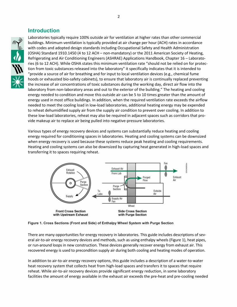
Figure 1. Cross Sections (Front and Side) of Enthalpy Wheel System with Purge Section
There are many opportunities for energy recovery in laboratories. This guide includes descriptions of sev-eral air-to-air energy recovery devices and methods, such as using enthalpy wheels (Figure 1), heat pipes, or run-around loops in new construction. These devices generally recover energy from exhaust air. This recovered energy is used to precondition supply air during both cooling and heating modes of operation. In addition to air-to-air energy recovery options, this guide includes a description of a water-to-water heat recovery system that collects heat from high-load spaces and transfers it to spaces that require reheat. While air-to-air recovery devices provide significant energy reduction, in some laboratory facilities the amount of energy available in the exhaust air exceeds the pre-heat and pre-cooling needed

3
to maintain supply air conditions. During these periods of time, controls typically reduce the energy recovery capacity to match the reduced load. If the energy recovered in the exhaust is not needed then it is rejected from the facility. By using a water-to-water recovery system, it is possible to significantly reduce overall building energy use by reusing heating or cooling energy generated in the building before it is rejected to the outdoors. Laboratory managers are encouraged to perform a life-cycle cost analysis of an energy-recovery tech-nology to determine the feasibility of its application in their laboratory. Usually, the shortest payback periods occur when the heating and cooling load reduction provided by an energy recovery system allows the laboratory to install and use smaller heating (e.g., hot water or steam) and cooling (e.g., chilled water) systems that eliminate energy waste. Technology Description
Air-to-Air Recovery Devices Air-to-air energy recovery devices exchange energy from one stream of air to another. The air being exhausted contains sensible (heat) and latent (water vapor) energy. Both types of energy can be recovered; however, not all air-to-air recov-ery devices exchange both types of energy. The effectiveness of an energy recovery device reflects the efficiency of the device in recovering available energy. Most devices have a rating for sensible effectiveness; some also have a rating for latent effectiveness and total effectiveness. It should be not-ed that in humidified buildings in cold climates, the actual performance of the energy recovery device may be limited (reduced effectiveness) by controls that prevent freezing or moisture condensation in the exhaust air stream. These air-to-air energy recovery devices increase the pres-sure drop that must be provided by either the supply or ex-haust fans. Enthalpy wheels generally have a lower pressure drop than heat pipes and run-around loops, although actual pressure drop depends on the particular design. An addition-al pressure drop of no more than 1-inch water gauge (1-in. w.g.) in the supply and exhaust air streams is a reasonable design goal, and it will minimize the increase in fan energy associated with these devices. For example, an increase in pressure drop of 1-in. w.g. on a 76% efficient fan and a 95% efficient motor assembly results in an increase in fan energy of 0.16 watt per cubic foot of air per minute (W/cfm). The total increase for supply and exhaust fans together in this example would be around 0.32 W/cfm. For laboratory applications, the design face velocity of recovery devices in air handling systems is usually 500 fpm. However, lower face velocities will result in lower pressure-drops, higher effectiveness, and lower operating costs. The trade-off is physically larger air handling equipment, larger mechanical space requirements and, possibly, higher first-cost. It is important to note that an energy recovery device will operate more efficiently with a variable-air-volume (VAV) system than with a constant-volume system, because VAV systems typically operate at face velocities lower than those of the peak design condition. If a
Key Terms Effectiveness: The ratio of actual energy recovered to theoretical energy that could be recovered.
Latent energy: The energy contained in moisture.
Latent effectiveness: Proportional to the ratio of the difference between the humidity ratio of the outside air and the supply air, and the difference between the humidity ratio of the exhaust air and the outside air.
Sensible energy: The energy associated with a temperature difference.
Sensible effectiveness: Proportional to the ratio of the difference between the dry-bulb temperature of the outside air and supply air, and the difference be-tween the dry-bulb temperature of the exhaust air and the outside air.
Total effectiveness: Proportional to the ratio of the difference between the enthal-py of the outside air and the supply air, and the difference between the enthalpy of the exhaust air and the outside air.

4
redundant air handler is included in the design, lower operating pressure drop can be accomplished simply by operating the standby unit without requiring an increase in the size and cost of air handling units. Enthalpy wheels. Enthalpy wheels, or rotary heat exchangers, transfer sensible or latent energy or both between the exhaust air and the incoming outside air (Figure 1). The supply and exhaust streams must be located next to each other. Sometimes referred to as desiccant wheels, both sensible-only wheels and total-energy wheels are available. A 50,000 cfm total-energy wheel can have a sensible and latent effectiveness as high as 75%, which results in a total effectiveness of 75%. Control of the wheel at part loads is accomplished by varying the speed of the wheel, using a bypass duct or both. The type of desiccant used in a total energy wheel must be designed to transfer only moisture and not airborne contaminants. To further reduce potential contamination of the supply air stream, the wheel is flushed with supply air that is deflected by a damper in the purging section of the rotor. The damper redirects supply air leaving the wheel to the inlet side of the wheel exhaust. The purge section utilizes the pressure difference between the supply air and exhaust air streams (see Figure 1). Purge volumes for laboratory applications are typically between 5% and 10%, so additional fan energy is required to move this air. While the 2008 ASHRAE Systems and Equipment Handbook indicates that energy wheels have a potential for air transfer in the range of 0.5 to 10%, some vendors indicate significantly lower transfer (in range of 0.04% from independent testing) for wheels designed for critical applications that also include a purge section. For example, the Whitehead Biomedical Research Building at Emory Uni-versity in Atlanta, Georgia, uses enthalpy wheels for energy recovery between the supply and exhaust air streams. The installation cost for the wheels was reported at $425,000, and anticipated energy sav-ings are $125,000 per year. The simple payback is less than four years. Total-energy recovery devices provide the highest effectiveness for sensible and total energy recovery and reductions in energy use. However, it is recommended that laboratory managers compare ASHRAE Interpretation IC 62.1-2010-1 (approved January 29, 2011) and the latest International Mechanical Code (IMC) section 514 on energy recovery systems, when applicable, before considering application of energy recovery wheels in laboratory systems exhausting fume hoods and chemical storage rooms (identified in ASHRAE Standard 62.1-2010 as being Class 4 air). This ASHRAE interpretation identified conflicting language within the ASHRAE Standard 62.1 with regard to transfer of chemicals in the exhaust air into air intakes or operable windows. As noted, various industry guidelines appear to stipulate a non-zero based acceptable limit on Class 4 contaminants passing from exhaust stacks into air intakes while the ASHRAE interpretation response and the IMC limit energy recovery devices to absolutely NO transfer of air or contaminants. Heat pipes. Heat pipes transfer only sensible energy between airflow streams. In heat pipe applications, the supply and exhaust air streams are typically next to one another, although some modified or “split” heat pipes allow the air streams to be separated with some also requiring pumping units to function properly. The sensible effectiveness of heat pipes is between 45% and 65%. The 2008 ASHRAE Systems and Equip-ment Handbook indicates that heat pipes have a potential for air transfer in the range of 0 to 1%, with the higher value typically associated with heat pipes that have tilt-type control. Some heat pipes have no mov-ing parts, and failure of the entire unit is rare. A tube may malfunction, but other tubes continue to trans-fer energy. Heat pipes can be controlled for part-load operation with a bypass damper, bypass duct, or by tilting the unit. Vendors typically indicate that for frost control, the bypass damper should be located in the supply air section of the unit. For moderate temperature conditions, these same vendors indicate that to prevent transfer heat when not needed, a bypass damper should be located in the exhaust section or a

5
complete exhaust bypass of the unit should be used. In these moderate conditions when the outside air temperature is near to or slightly below the required supply air temperature, too much heat will be trans-ferred from the warmer exhaust air to the supply and could actually require mechanical cooling even though the system should be in the equivalent of an economizer mode. For example, with an outdoor air temperature of 55 degrees F and an exhaust temperature of 70 degrees F, an increase in supply air tem-perature of 6 to 7 degrees has been observed. In this observed condition, mechanical cooling was being used when not needed, showing the importance of the exhaust bypass. It should be noted that tilting heat pipes that have the potential for air transfer between exhaust and supply are likely subject to the same ASHRAE interpretation as total energy recovery wheels and will need to be reviewed and considered by the laboratory manager. Heat pipes can also be used as part of an indirect evaporative cooling process in which water is sprayed on the exhaust side of the pipe to pre-cool the supply air (Figure 2). This application has been successful at the Fox Chase Cancer Center in Philadelphia, Pennsylvania, and in the Process and Environmental Technology Laboratory at Sandia National Laboratories in Albuquerque, New Mexico. Consideration can also be given to recovering and using cold cooling-coil condensate from the air handler as a supple-mental source of makeup water in the evaporative cooling process. If direct evaporative cooling is used in the exhaust airstream, connection of the drain to the laboratory waste system may be required due to the air washing effect of the evaporative cooler.
Figure 2. Heat Pipe System
Run-around loops. Run-around loops circulate a fluid between two air streams. This technology may seem familiar to most designers because it usually involves additional coils and pumps. The air streams do not need to be next to one another, and there are no cross-contamination issues. These units provide only sensible energy recovery similar to heat pipes. While run-around loops can have a theoretical sensible effectiveness of between 55% and 65%, as previously noted in humidified buildings in cold climates, the actual performance of the energy recovery device will likely be limited by controls that prevent freezing or moisture condensation in the exhaust air stream to an effectiveness value of around 30% on a design day where temperatures approach 0 degrees F outdoors. It should be noted that this limitation for humidified buildings occurs only when

6
conditions are below roughly 20 degrees F. Above 20 degrees F run-around loops can provide most or all pre-heat needed without supplemental sources of energy. In the U.S. Department of Agriculture’s new laboratory in Ames, Iowa, the main preheat coil and the run-around loop supply pre-heat coil are combined, so there was a lower additional pressure drop in the supply system when compared to a system with separate energy recovery and preheat coils. Run-around loops are well-suited for transferring energy between process loads and ventilation air. Fred Hutchinson Cancer Research Center in Seattle, Washington, uses a run-around loop to take heat rejected from the process cooling water system to preheat outside air, thus providing free cooling of the process cooling water. Run-around loops and heat pipes can also be used to reduce reheat energy by transferring heat from the outdoor air to a reheat device located after a dehumidification cooling coil in warm, humid climates. The energy recovery device pre-cools the outside air before the air enters the main dehumidification cooling coil, and the dehumidification reheat device reheats the air leaving the main cooling coil. This pre-cooling and reheating can be accomplished with a device that wraps around the cooling coil, often called a “wrap-around loop.” It can also be accomplished with two energy recovery stages between the supply and exhaust air streams on either side of the cooling coil. A wrap-around loop can be added to a runaround energy recovery loop by adding a coil on the exit side of the cooling coil (Figure 3). Packaged three-coil run-around loops with capacity to recover heat for pre-heating in winter and for re-heating after dehumidification in the summer (with optional coil) are also available (Figure 3). Dehumidification and reheat coils should be considered where internal loads do not require the cold temperatures provided off of the dehumidification coil to meet space needs. A detailed engineering analysis is required to identify a supply air temperature that can take advantage of this recovered reheat energy while balancing the energy penalty of the coil pressure drop.
Figure 3. Run-Around Energy Recovery Loop with Dehumidification
7
Variations on Basic Air-System Energy Recovery. Concepts that combine the above systems can also be considered. These include using heat pipes instead of glycol for combination preheat and reheat systems. Vendors can also provide multiple energy recovery wheels in dehumidification units to opti-mize energy recovery. The Viral Immunology Center at Georgia State in Atlanta, Georgia, used a packaged rooftop ventilation- dehumidification unit with two heat pipes. In the summer, one heat pipe pre-cools the outside air by transferring heat to the exhaust air, the mechanical system DX coil sub-cools the air, and the other heat pipe reheats the air with heat recovered from the exhaust air. In the winter, both heat pipes are used to heat the air. Water-to-Water Recovery Devices While air-to-air recovery devices provide significant energy reduction, additional energy recovery is pos-sible in laboratories where common systems are required to serve both low-load and high-load spaces. While separation of high-load spaces onto dedicated systems would allow systems serving low- load spaces to take advantage of the above reheat recovery options and also supply air temperature- reset control, the challenge in laboratory buildings where loads are driven by research equipment is that a space with a high load today could be a space with low load tomorrow. Equipment with higher heat rejection could also be added to spaces currently operating at low internal load. This diversity in loads is described in the Labs 21 Laboratory Modeling Guideline using ASHRAE 90.1-2007. The diversity indicated in the guide suggests load profiles (some spaces at 100% load with remaining at significantly diversified load) are consistent with recommendations for right sizing mechanical systems while also acknowledg-ing that some spaces will continue to have high internal loads. For laboratories where loads will vary from research project to research project, systems that have the ability to recover energy from these few high-load spaces can use this normally rejected energy to provide reheat in low-load spaces. The following is a description of one such system. To assess the viability of one type of water-to-water energy recovery system, the design team must review load profiles that reflect the anticipated operation of a laboratory building. The Labs 21 Modeling Guide developed suggested load profiles that have since been incorporated into the ASHRAE 90.1-2010 User’s Manual for use as a starting point for discussions on project specific profiles. The recommenda-tion is to model a small number of spaces with constant high internal load (10% to 15% of lab spaces), and to model the remaining with a largely diversified load (85% to 90% of lab spaces). The following graphs indicate sample design load profiles for low and high-load labs and lab support spaces (Figure 4).

8
Figure 4. Sample Internal Load Profiles for Laboratory and Laboratory Support Spaces
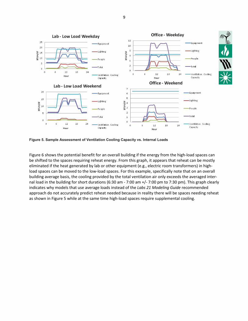
The next step in the feasibility review is to assess the cooling load capacity of the ventilation air being provided. Figure 5 shows an overlay of the cooling capacity from and occupied/unoccupied ventilation reset system and the diversified internal loads of low-load spaces. As can be seen, there are a number of hours per day when the ventilation cooling capacity exceeds the internal loads of these low-load spaces. It is in these spaces that reheat energy is usually expended. As discussed earlier, while these low-load spaces require reheat, most designs also have a small number of high-load spaces where internal cooling requirements can be met by supplemental cooling units rather than increasing ventilation air. These supplemental cooling units allow recovery of the heat being generated in these spaces. Since the loca-tion of these high-load spaces will likely change during use there may be no way to separate the high-load spaces onto a dedicated system so alternative methods of energy recovery should be reviewed.
9
Figure 5. Sample Assessment of Ventilation Cooling Capacity vs. Internal Loads
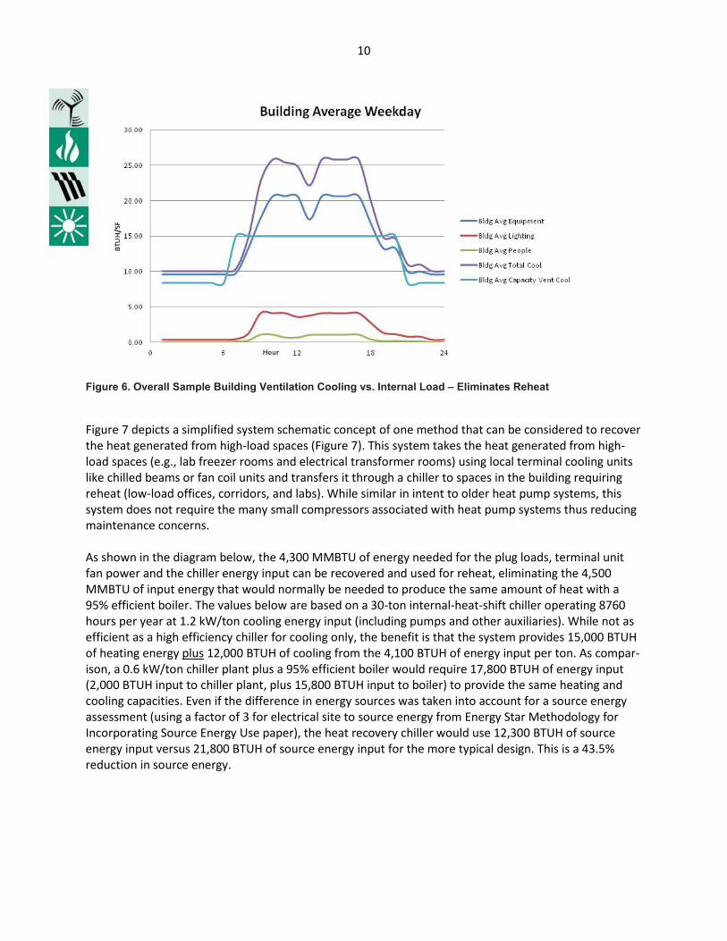
Figure 6 shows the potential benefit for an overall building if the energy from the high-load spaces can be shifted to the spaces requiring reheat energy. From this graph, it appears that reheat can be mostly eliminated if the heat generated by lab or other equipment (e.g., electric room transformers) in high-load spaces can be moved to the low-load spaces. For this example, specifically note that on an overall building average basis, the cooling provided by the total ventilation air only exceeds the averaged inter-nal load in the building for short durations (6:30 am - 7:00 am +/- 7:00 pm to 7:30 pm). This graph clearly indicates why models that use average loads instead of the Labs 21 Modeling Guide recommended approach do not accurately predict reheat needed because in reality there will be spaces needing reheat as shown in Figure 5 while at the same time high-load spaces require supplemental cooling.
10
Figure 6. Overall Sample Building Ventilation Cooling vs. Internal Load – Eliminates Reheat
Figure 7 depicts a simplified system schematic concept of one method that can be considered to recover the heat generated from high-load spaces (Figure 7). This system takes the heat generated from high- load spaces (e.g., lab freezer rooms and electrical transformer rooms) using local terminal cooling units like chilled beams or fan coil units and transfers it through a chiller to spaces in the building requiring reheat (low-load offices, corridors, and labs). While similar in intent to older heat pump systems, this system does not require the many small compressors associated with heat pump systems thus reducing maintenance concerns. As shown in the diagram below, the 4,300 MMBTU of energy needed for the plug loads, terminal unit fan power and the chiller energy input can be recovered and used for reheat, eliminating the 4,500 MMBTU of input energy that would normally be needed to produce the same amount of heat with a 95% efficient boiler. The values below are based on a 30-ton internal-heat-shift chiller operating 8760 hours per year at 1.2 kW/ton cooling energy input (including pumps and other auxiliaries). While not as efficient as a high efficiency chiller for cooling only, the benefit is that the system provides 15,000 BTUH of heating energy plus 12,000 BTUH of cooling from the 4,100 BTUH of energy input per ton. As compar-ison, a 0.6 kW/ton chiller plant plus a 95% efficient boiler would require 17,800 BTUH of energy input (2,000 BTUH input to chiller plant, plus 15,800 BTUH input to boiler) to provide the same heating and cooling capacities. Even if the difference in energy sources was taken into account for a source energy assessment (using a factor of 3 for electrical site to source energy from Energy Star Methodology for Incorporating Source Energy Use paper), the heat recovery chiller would use 12,300 BTUH of source energy input versus 21,800 BTUH of source energy input for the more typical design. This is a 43.5% reduction in source energy.
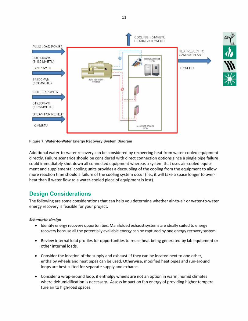
11
Figure 7. Water-to-Water Energy Recovery System Diagram
Additional water-to-water recovery can be considered by recovering heat from water-cooled equipment directly. Failure scenarios should be considered with direct connection options since a single pipe failure could immediately shut down all connected equipment whereas a system that uses air-cooled equip-ment and supplemental cooling units provides a decoupling of the cooling from the equipment to allow more reaction time should a failure of the cooling system occur (i.e., it will take a space longer to over-heat than if water flow to a water-cooled piece of equipment is lost).
Design Considerations The following are some considerations that can help you determine whether air-to-air or water-to-water energy recovery is feasible for your project.
Schematic design
• Identify energy recovery opportunities. Manifolded exhaust systems are ideally suited to energy recovery because all the potentially available energy can be captured by one energy recovery system.
• Review internal load profiles for opportunities to reuse heat being generated by lab equipment or other internal loads.
• Consider the location of the supply and exhaust. If they can be located next to one other, enthalpy wheels and heat pipes can be used. Otherwise, modified heat pipes and run-around loops are best suited for separate supply and exhaust.
• Consider a wrap-around loop, if enthalpy wheels are not an option in warm, humid climates where dehumidification is necessary. Assess impact on fan energy of providing higher tempera-ture air to high-load spaces.

12
• Assess the risk associated with cross-contamination of the air streams. Purge sections on enthalpy wheels reduce cross-contamination to below 0.1%, according to vendor independent-testing data. There are limited cross-contamination issues with heat pipes to be addressed and none with run-around loops.
• Be sure to address the potential for fouling and corrosion of the devices. Routine maintenance and controls may be sufficient, although the most suitable equipment depends on the chemicals being released into the air stream. Select air filters with a low pressure drop.
• Prepare and review energy models and note where all energy is going. If heating or cooling energy is being rejected to the outdoors while heating or cooling energy is being used to condition spac-es, consider systems that recovery energy. This means exhaust air should be discharged at condi-tions as close to incoming air as possible which can be accomplished using water-to-water energy recovery options.
• Review energy models for periods of time where heat is being rejected through a cooling plant while energy is being expended to provide heat in the building. An example of this occurring is shown in Table 4 where the energy cost of the” Terminal Cooling with Campus Chilled Water” option exceeded not only the “Heat Shift Chiller” option but also the base case “All Air System” option.
• Determine the space requirement for additional equipment needed and its impact on design and costs.
• Estimate operation and maintenance costs for the device, as well as replacement costs.
• Calculate the impact of energy recovery on energy costs.
• Include the cost benefit of being able to downsize the heating and cooling systems.
Design development and construction documents
• Identify appropriate control strategies for part-load operation and for preventing condensation and potential freezing. Using bypass ducts reduces the increase in fan energy.
• Clearly define the commissioning of the energy recovery device.
Codes and Standards As with all building components, various codes and standards apply to energy recovery. There are standards for testing the performance of the equipment and standards that specify when energy recovery must or must not be applied. American Industrial Hygiene Association codes and standards affecting laboratories can be found on the Web (see www.aiha.org/insideaiha/volunteergroups/labHandScommittee/Pages/default.aspx/htmljavascript.htm, accessed 12-11). A brief overview of codes and standards pertaining to energy recovery:
• Air-Conditioning and Refrigeration Institute (ARI) Standard 1060-2001 for Air-to-Air Energy Recov-ery Ventilation Equipment rates the sensible, latent, and total effectiveness of equipment, exclud-ing run-around loops. The ratings are performed by an independent laboratory per ASHRAE 84 (see below), except as amended by ARI 1060. The ARI-certified product directory (latest edition) is
13
a useful resource for identifying various manufacturers and their products and for comparing effectiveness ratings.
• American National Standards Institute (ANSI)/ASHRAE Standard 84-2008, Method of Testing Air-to-Air Heat Exchangers, specifies the data, equipment, and reporting procedures for testing the sensible, latent, and total effectiveness of air-to-air heat exchangers. There are similar Canadian and European standards.
• In the most recently published version of the International Mechanical Code (2012), section 514 covers the installation of energy recovery ventilation systems. This section prohibits the use of all types of energy recovery ventilation, including heat pipes and run-around loops in hazardous exhaust systems as defined in section 510. A code variance may be required if energy recovery is to be considered in a laboratory hazardous fume hood exhaust system.
• National Fire Protection Association (NFPA) Standard 45-2011 states that, if there is a chance of cross-contamination between air streams, air-to-air energy recovery can be used only on general exhaust as defined in AIHA/ANSI Standard Z9.5-2003 Laboratory Ventilation. This code has not been adopted by all states, although it raises concern for laboratory managers. At the National Institutes of Health (NIH) Louis Stokes Laboratory and the Nidus Center in St. Louis, the general exhaust system is separate from the fume hood exhaust, and there is an enthalpy wheel on the general exhaust only. NIH had to use stainless steel ductwork for the fume hood exhaust, because the exhaust was no longer being diluted enough to allow for galvanized ducts.
• The ASHRAE 90.1-2010 energy efficiency standard states that laboratories require as a minimum setback of airflow and sensible energy recovery on fan systems of 5,000 cfm or greater. Note that the calculation of fan power limitations in the standard includes an adjustment for energy recovery.
14
Performance Examples Air-to-air energy recovery reduces energy use and can significantly reduce heating and cooling system sizes. A large installation of enthalpy wheels done in 1991 at the Johns Hopkins Ross Research Building has resulted in millions of dollars in energy savings. All exhaust, including fume-hood and biological safety cabinet exhaust, is passed through the enthalpy wheels. The equipment paid for itself in first-cost savings because the hot water and chilled water systems could be downsized (see Engineered Systems, September 1995). The enthalpy wheels have performed so well that Johns Hopkins installed enthalpy wheels in its new lab buildings, including the Cancer Research Building.
Key Issues Concerning Energy Recovery in Laboratories Integration of energy recovery into a laboratory ventilation system requires careful consideration of some key issues. Design teams have taken different approaches to handling these issues, which demonstrates the importance of considering all options.
Contamination – If cross-contamination from fume hood exhaust is an issue, consider heat pipes or run-around loops. Another approach is isolating the fume hood exhaust and recovering energy from the general exhaust only. Total energy recovery is the most efficient option in general exhaust. Note that the chemicals in the fume hood exhaust may become too concentrated and require additional treatment if separated.
Space requirements and duct adjacencies – Enthalpy wheels and most types of heat pipes require the main supply and exhaust ducts to be located next to each other; run-around loops do not. Additional space is required for the energy recovery device, typically in the makeup air unit and main exhaust duct. Run-around loops also require space for a pump.
Hazardous chemicals – If isolating the fume hood exhaust or condensate from a heat recovery device results in too high a concentration of volatile organic compounds, disposal could become a problem. Potential hazard-ous waste issues need to be addressed early on. The applicable mechanical code includes specific items that cannot be manifolded.
Humidity – If humidity is being controlled, estimates indicate that humidification energy can increase overall steam or hot water energy use by an estimated 25%. The potential energy savings with energy recovery increases and so do the possible alternatives. Desiccant wheels can be used for dehumidification, wrap-around coils can be used for reducing reheat energy, and evaporative cooling can be used for humidification. Avoid over-specifying control of humidity; the wider the control range, the less energy used.
Maintenance – Maintenance differs according to the type of energy recovery and the application. Heat pipes appear to have the lowest maintenance requirements, followed by run-around loops. Periodic cleaning needs depend on the fouling and corrosion potential of the exhaust air, but cleaning is critically important to maintain-ing the performance of the equipment.
Part-load operation – Outside-air bypass dampers can be used for part-load operation to minimize over-heating, overcooling, and fan energy use. They can also serve to prevent condensation and frosting. Alterna-tively, you can vary the wheel speed on enthalpy wheels, change the tilt on heat pipes, or vary the flow on run-around loops.
Redundancy – Laboratories usually have redundant chillers and boilers to ensure control over a room’s climate conditions at all times. If the capacity provided by energy recovery is not accounted for in sizing the chilled water and hot water systems, then the systems should at least be optimized to operate with the lower loads resulting from the use of energy recovery. Otherwise, the chillers and boilers may operate very ineffi-ciently at low part loads.
In 2002, an energy analysis of enthalpy wheels, heat pipes, and run-around loops was performed for Laboratories for the 21st Century (http://ateam.lbl.gov/Design-Guide/Docs/Labs21EnergyAnal_33410.pdf). It analyzed a typical 100,000-square-foot (sf) laboratory in four locations:

15
• Air-to-air energy recovery reduces gas usage for space heating and reheating for dehumidification by more than 35% in all climates (see Table 1).
• Savings in peak electricity demand associated with an enthalpy wheel depend on climate (see Table 2). No savings are predicted for heat pipes and run-around loops, because the increase in the fan energy demand offsets the decrease in the cooling energy demand associated with these technologies.
• Annual energy cost savings are $0.27 to $1.95/cfm of fan air flow (see Table 3). Enthalpy wheels, with sensible and latent heat recovery, appear to be cost-effective in all climates. The cost savings obtained with heat pipes and run-around loops are relatively small in warm, humid climates; how-ever, using these devices as wrap-around loops for dehumidification may be cost-effective.
• Only in the hot, humid climate of Atlanta did annual electricity savings occur with the enthalpy wheel; in the other climates, the increase in annual fan energy offset the annual electricity savings.
• The greatest reduction (approximately 20%) in chiller size occurs with enthalpy wheels in humid climates; the savings are approximately half this amount with sensible-only recovery devices. In the dry Denver climate, the potential reduction is 10% with all three devices.
• The minimum reduction in boiler size is 15% with any of the devices. If the building is also being humidified in the winter, the additional latent energy recovery with enthalpy wheels results in up to a 50% reduction in heating and humidification requirements.
At the 120,000-sf Fox Chase Cancer Center in Philadelphia, heat pipes with bypass sections were installed in two 30,000-cfm air handling units. The incremental cost for heat pipes with the indirect

16
evaporative cooling option on the exhaust was $300,000. Anticipated energy cost savings were $72,510, resulting in a simple payback of 4 years. In addition to the more typical air to air energy recovery systems, the energy assessment for a 100,000-sf biomedical research building in Massachusetts indicates the significant potential energy cost benefits of an internal heat recovery chiller (Table 4) as compared to an all air system and to a system that uses terminal cooling units to reject heat out of the facility rather than using it within the building. The in-crease in cooling energy and cost for the terminal unit with campus chilled water is due to the reduction in air-side economizer hours and the year-round chilled water needed from the campus. The decrease in fan energy with the terminal cooling options is due to the reduced 100% outside air ventilation airflow required combined with the use of low pressure drop local terminal cooling (i.e., 100% outside air units have higher pressure drop than local cooling units). Table 4. Comparison of Heat Shift Chiller to All-Air VAV and Terminal Cooling Systems without Energy Recovery Chiller
Conclusion Installing energy recovery systems can substantially reduce the cost and use of energy in laboratories. Selecting an appropriate energy recovery technology, properly designing the system, meeting the appli-cable codes, and commissioning the system are all important. When an energy recovery system is de-signed, installed, and operated correctly, it will provide significant energy and environmental benefits. Acknowledgements We wish to thank the original primary author of this guide Sue Reilly of Group14 Engineering and Michael Walsh of R.G. Vanderweil Engineers, LLP who provided updates for this guide revision. This guide would not have been possible without the additional contributions of Michael Dausch of Johns Hopkins; and John Fisher of SEMCO; Geoffrey Bell of LBNL. Nancy Carlisle, Otto Van Geet, Paula Pitchford, and Bruce Green, editors, and Susan Sczepanski, graphic designer, all of NREL, also contrib-uted to this best practices guide.

17
For More Information The different types of air-to-air energy recovery devices are discussed in numerous sources. For exam-ple, the American Society of Heating, Refrigerating, and Air-Conditioning Engineers (ASHRAE) Heating, Ventilating, and Air-Conditioning Systems and Equipment Handbook covers a wide range of devices, compares their performance, and identifies appropriate applications. The ASHRAE Laboratory Design Guide by McIntosh et al. includes a chapter on energy recovery and discusses laboratory-specific concerns. Also, A Design Guide for Energy-Efficient Research Laboratories (http://ateam.lbl.gov/Design-Guide/) is available in electronic format from Lawrence Berkeley National Laboratory. This searchable document includes a discussion of different types of energy recovery as well as case studies. Also, the U.S. Environmental Protection Agency and the U.S. Department of Energy have prepared several Laboratories for the 21st Century case studies (www1.eere.energy.gov/femp/program/labs21_casestudies.html). Several case studies feature energy recovery; for an example of enthalpy wheels, see the studies on Pharmacia Building Q, the Nidus Center, and Building 50 at the National Institutes of Health; for an example of heat pipes, see the study on the PETL at Sandia National Laboratories, Albuquerque. Several other good sources of information are listed below. Air Conditioning and Refrigeration Institute (ARI). 2001. Air-to-Air Energy Recovery Ventilation Equip-ment Certified Product Directory. ARI, Arlington, Virginia (www.ahrinet.org).
ARI Stand. 1060. 2001. Rating Air-to-Air Energy Recovery Ventilation Equipment. ARI, Arlington, Virginia.
ANSI/ASHRAE Standard 84-2008. 2007. Method of Testing Air-to-Air Heat Exchangers. American Society of Heating, Refrigerating and Air-Conditioning Engineers, Inc., Atlanta, Georgia (www.ashrae.org).
Cockerham, K. 2000 (July). “A Tale of Two Systems.” Consulting Specifying Engineer.
DiBlasio, R. 1995 (September). “Conditioning a Research Facility.” Engineered Systems.
Gibson, Tom, 1999. “Special Ventilation System Helps Prevent Release of Dangerous Agents at Georgia State,” The News: Air Conditioning, Heating and Refrigeration.
International Code Council, 2012. International Mechanical Code. ICC, Falls Church, Virginia.
McIntosh, I.; Dorgan, C.B.; and Dorgan, C.E., 2001. ASHRAE Laboratory Design Guide. American Society of Heating, Refrigerating and Air-Conditioning Engineers, Inc., Atlanta, Georgia.
National Fire Protection Association 45, 2010. Standard on Fire Protection for Laboratories Using Chemicals. NFPA, Quincy, Massachusetts.
National Wildlife Federation, 2002. Emory University Campus Ecology Yearbook 2001-2002. NWF, Reston, Virginia.
Paarporn, S., P.E., 1999. “Run-around Loop Heat Recovery with Dehumidification System.” ASHRAE Journal, June.
Reilly, S., and Van Geet, O., 2003. Laboratories for the 21st Century Energy Analysis.
18
Contacts Laboratories for the 21st Century:
Will Lintner, P.E. U.S. Department of Energy Federal Energy Management Program 1000 Independence Ave., S.W. Washington, DC 20585 202-586-3120 [email protected] On Energy Recovery: Otto Van Geet, P.E. National Renewable Energy Laboratory 15013 Denver West Parkway Golden, CO 80401 303-384-7369 [email protected] Michael J. Walsh, P.E. R.G. Vanderweil Engineers, LLP 274 Summer St. Boston, MA 02210 617-423-7423 [email protected] Sue Reilly, P.E. Group14 Engineering 1554 Emerson St. Denver, CO 80218 303-861-2070 [email protected]
Laboratories for the 21st Century U.S. Environmental Protection Agency Office of Administration and Resources Management www.labs21century.gov
In partnership with the U.S. Department of Energy Energy Efficiency and Renewable Energy www.eere.energy.gov/ Prepared at the National Renewable Energy laboratory A DOE national laboratory
DOE/GO-102012-3503 June 2012 Printed with a renewable-source ink on paper containing at least 50% wastepaper, including 10% post consumer waste.