Laborator Ventilation Sstems - HEMCO Corporation Images/Catalog pdfs...Laborator Ventilation Sstems...
16
Fume Hood Exhaust Blowers HEPA & Carbon Filtration Ducting & Exhaust Fume Scrubbers Manifolds ISO 9001:2015 Certified Company HEMCO R
Transcript of Laborator Ventilation Sstems - HEMCO Corporation Images/Catalog pdfs...Laborator Ventilation Sstems...

Laboratory Ventilation Systems
Fume Hood Exhaust Blowers
HEPA & Carbon Filtration
Ducting & Exhaust
Fume Scrubbers
Manifolds
ISO 9001:2015 Certified CompanyHEMCOR
2
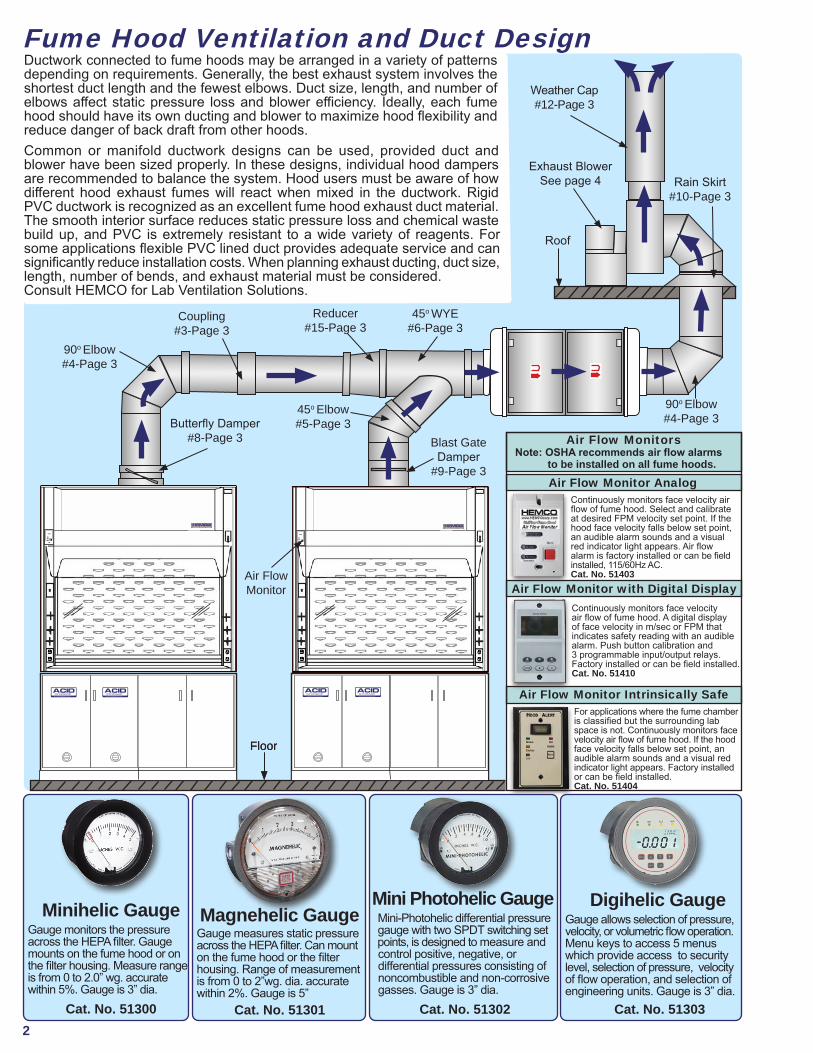
Fume Hood Ventilation and Duct Design
90o Elbow#4-Page 3
Coupling#3-Page 3
Reducer#15-Page 3
45o WYE#6-Page 3
Butterfly Damper#8-Page 3
45o Elbow#5-Page 3
Blast Gate Damper
#9-Page 3
Air FlowMonitor
Floor
Ductwork connected to fume hoods may be arranged in a variety of patterns depending on requirements. Generally, the best exhaust system involves the shortest duct length and the fewest elbows. Duct size, length, and number of elbows affect static pressure loss and blower efficiency. Ideally, each fume hood should have its own ducting and blower to maximize hood flexibility and reduce danger of back draft from other hoods.Common or manifold ductwork designs can be used, provided duct and blower have been sized properly. In these designs, individual hood dampers are recommended to balance the system. Hood users must be aware of how different hood exhaust fumes will react when mixed in the ductwork. Rigid PVC ductwork is recognized as an excellent fume hood exhaust duct material. The smooth interior surface reduces static pressure loss and chemical waste build up, and PVC is extremely resistant to a wide variety of reagents. For some applications flexible PVC lined duct provides adequate service and can significantly reduce installation costs. When planning exhaust ducting, duct size, length, number of bends, and exhaust material must be considered. Consult HEMCO for Lab Ventilation Solutions.
Rain Skirt#10-Page 3
Exhaust BlowerSee page 4
Roof
Weather Cap#12-Page 3
90o Elbow#4-Page 3
Air Flow Monitor with Digital Display
Minihelic GaugeGauge monitors the pressureacross the HEPA filter. Gauge mounts on the fume hood or on the filter housing. Measure range is from 0 to 2.0” wg. accurate within 5%. Gauge is 3” dia.
Cat. No. 51300
Magnehelic GaugeGauge measures static pressure across the HEPA filter. Can mount on the fume hood or the filter housing. Range of measurement is from 0 to 2”wg. dia. accurate within 2%. Gauge is 5”
Cat. No. 51301
Digihelic GaugeGauge allows selection of pressure, velocity, or volumetric flow operation. Menu keys to access 5 menus which provide access to security level, selection of pressure, velocity of flow operation, and selection of engineering units. Gauge is 3” dia.
Cat. No. 51303
Mini Photohelic Gauge Mini-Photohelic differential pressure gauge with two SPDT switching set points, is designed to measure and control positive, negative, or differential pressures consisting of noncombustible and non-corrosive gasses. Gauge is 3” dia. Cat. No. 51302
Air Flow Monitor Analog
Air Flow Monitors Note: OSHA recommends air flow alarms to be installed on all fume hoods.
Air Flow Monitor Intrinsically SafeFor applications where the fume chamber is classified but the surrounding lab space is not. Continuously monitors face velocity air flow of fume hood. If the hood face velocity falls below set point, an audible alarm sounds and a visual red indicator light appears. Factory installed or can be field installed. Cat. No. 51404
Continuously monitors face velocity air flow of fume hood. A digital display of face velocity in m/sec or FPM that indicates safety reading with an audible alarm. Push button calibration and 3 programmable input/output relays. Factory installed or can be field installed. Cat. No. 51410
Continuously monitors face velocity air flow of fume hood. Select and calibrate at desired FPM velocity set point. If the hood face velocity falls below set point, an audible alarm sounds and a visual red indicator light appears. Air flow alarm is factory installed or can be field installed, 115/60Hz AC. Cat. No. 51403
Floor
STORAGEACID
visit www.HEMCOcorp.com
STORAGEACID
visit www.HEMCOcorp.com
STORAGEACID
visit www.HEMCOcorp.com
STORAGEACID
visit www.HEMCOcorp.com
3
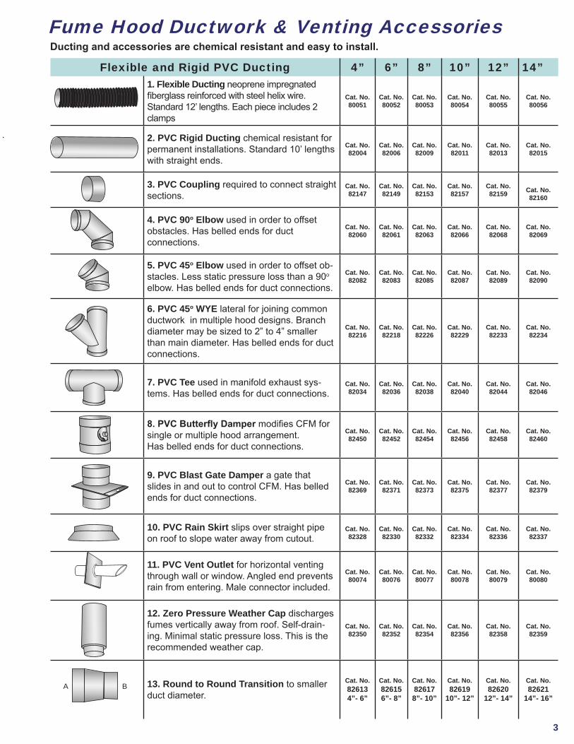
Flexible and Rigid PVC Ducting 4” 6” 8” 10” 12” 14”1. Flexible Ducting neoprene impregnated fiberglass reinforced with steel helix wire. Standard 12’ lengths. Each piece includes 2 clamps
Cat. No. 80051
Cat. No. 80052
Cat. No. 80053
Cat. No. 80054
Cat. No. 80055
Cat. No.80056
2. PVC Rigid Ducting chemical resistant for permanent installations. Standard 10’ lengths with straight ends.
Cat. No. 82004
Cat. No. 82006
Cat. No. 82009
Cat. No. 82011
Cat. No. 82013
Cat. No. 82015
3. PVC Coupling required to connect straight sections.
Cat. No. 82147
Cat. No. 82149
Cat. No. 82153
Cat. No. 82157
Cat. No. 82159 Cat. No.
82160
4. PVC 90o Elbow used in order to offset obstacles. Has belled ends for duct connections.
Cat. No. 82060
Cat. No. 82061
Cat. No. 82063
Cat. No. 82066
Cat. No. 82068
Cat. No. 82069
5. PVC 45o Elbow used in order to offset ob-stacles. Less static pressure loss than a 90o elbow. Has belled ends for duct connections.
Cat. No. 82082
Cat. No. 82083
Cat. No. 82085
Cat. No. 82087
Cat. No. 82089
Cat. No. 82090
6. PVC 45o WYE lateral for joining common ductwork in multiple hood designs. Branch diameter may be sized to 2” to 4” smaller than main diameter. Has belled ends for duct connections.
Cat. No. 82216
Cat. No. 82218
Cat. No. 82226
Cat. No. 82229
Cat. No. 82233
Cat. No. 82234
7. PVC Tee used in manifold exhaust sys-tems. Has belled ends for duct connections.
Cat. No. 82034
Cat. No. 82036
Cat. No. 82038
Cat. No. 82040
Cat. No. 82044
Cat. No.82046
8. PVC Butterfly Damper modifies CFM for single or multiple hood arrangement. Has belled ends for duct connections.
Cat. No.82450
Cat. No. 82452
Cat. No. 82454
Cat. No. 82456
Cat. No. 82458
Cat. No. 82460
9. PVC Blast Gate Damper a gate that slides in and out to control CFM. Has belled ends for duct connections.
Cat. No.82369
Cat. No. 82371
Cat. No. 82373
Cat. No. 82375
Cat. No. 82377
Cat. No. 82379
10. PVC Rain Skirt slips over straight pipe on roof to slope water away from cutout.
Cat. No. 82328
Cat. No. 82330
Cat. No. 82332
Cat. No. 82334
Cat. No. 82336
Cat. No. 82337
11. PVC Vent Outlet for horizontal venting through wall or window. Angled end prevents rain from entering. Male connector included.
Cat. No. 80074
Cat. No. 80076
Cat. No. 80077
Cat. No. 80078
Cat. No. 80079
Cat. No. 80080
12. Zero Pressure Weather Cap discharges fumes vertically away from roof. Self-drain-ing. Minimal static pressure loss. This is the recommended weather cap.
Cat. No. 82350
Cat. No. 82352
Cat. No. 82354
Cat. No. 82356
Cat. No. 82358
Cat. No.82359
13. Round to Round Transition to smaller duct diameter.
Cat. No. 826134”- 6”
Cat. No. 826156”- 8”
Cat. No. 826178”- 10”
Cat. No. 82619
10”- 12”
Cat. No. 82620
12”- 14”
Cat. No. 82621
14”- 16”
Fume Hood Ductwork & Venting Accessories
A B
Ducting and accessories are chemical resistant and easy to install.
4
Fume Hood Exhaust Blowers Ordering InfoUniFlow CE Fume Hoods
Hood Width
Hood Depth
Full Open cfm
1/2 Open cfm
30” 24” 378 189
36” 24” 460 230
48” 24” 654 327
60” 24” 1046 52372” 24”
UniFlow SE & LE Fume HoodsHood Width
Hood Depth
Full Open cfm
1/2 Open cfm
36” 30” 438 241
48” 30” 772 385
60” 30” 938 474
72” 30” 1162 592
96” 30” 1613 800
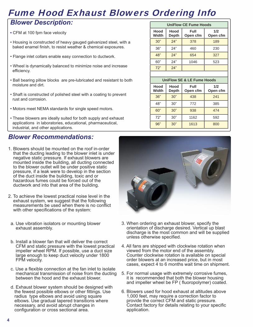
Blower Description: • CFM at 100 fpm face velocity
• Housing is constructed of heavy gauged galvanized steel, with a baked enamel finish, to resist weather & chemical exposures.
• Flange inlet collars enable easy connection to ductwork.
• Wheel is dynamically balanced to minimize noise and increase efficiency.
• Ball bearing pillow blocks are pre-lubricated and resistant to both moisture and dirt.
• Shaft is constructed of polished steel with a coating to prevent rust and corrosion.
• Motors meet NEMA standards for single speed motors.
• These blowers are ideally suited for both supply and exhaust applications in laboratories, educational, pharmaceutical, industrial, and other applications.
Blower Recommendations: 1. Blowers should be mounted on the roof in-order that the ducting leading to the blower inlet is under negative static pressure. If exhaust blowers are mounted inside the building, all ducting connected to the blower outlet will be under positive static pressure, if a leak were to develop in the section of the duct inside the building, toxic and or hazardous fumes could be forced out of the ductwork and into that area of the building.
2. To achieve the lowest practical noise level in the exhaust system, we suggest that the following measurements be used when there is no conflict with other specifications of the system:
a. Use vibration isolators or mounting blower exhaust assembly.
b. Install a blower fan that will deliver the correct CFM and static pressure with the lowest practical impeller wheel RPM. If possible, use a duct size large enough to keep duct velocity under 1800 FPM velocity.
c. Use a flexible connection at the fan inlet to isolate mechanical transmission of noise from the ducting between the hood and the exhaust blower. d. Exhaust blower system should be designed with the fewest possible elbows or other fittings. Use radius type elbows and avoid using square elbows. Use gradual tapered transitions where necessary, and avoid abrupt changes in configuration or cross sectional area.
3. When ordering an exhaust blower, specify the orientation of discharge desired. Vertical up blast discharge is the most common and will be supplied unless otherwise specified.
4. All fans are shipped with clockwise rotation when viewed from the motor end of the assembly. Counter clockwise rotation is available on special order blowers at an increased price, but in most cases, expect 4 to 6 months wait time on shipment.
5. For normal usage with extremely corrosive fumes, it is recommended that both the blower housing and impeller wheel be FP ( fluoropolymer) coated.
6. Blowers used for hood exhaust at altitudes above 1,000 feet, may require a correction factor to provide the correct CFM and static pressure. Contact factory for details relating to your specific application.
5
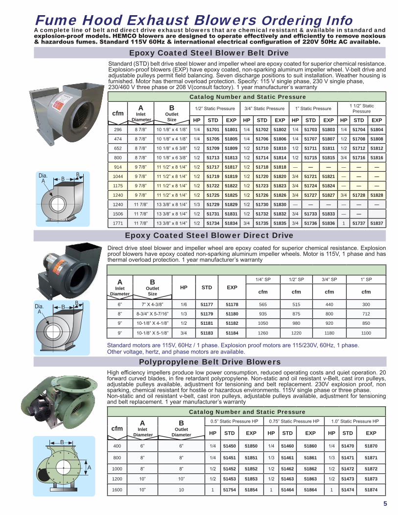
A complete line of belt and direct drive exhaust blowers that are chemical resistant & available in standard and explosion-proof models. HEMCO blowers are designed to operate effectively and efficiently to remove noxious & hazardous fumes. Standard 115V 60Hz & international electrical configuration of 220V 50Hz AC available.
Epoxy Coated Steel Blower Belt Drive
Standard motors are 115V, 60Hz / 1 phase. Explosion proof motors are 115/230V, 60Hz, 1 phase. Other voltage, hertz, and phase motors are available.
Direct drive steel blower and impeller wheel are epoxy coated for superior chemical resistance. Explosion proof blowers have epoxy coated non-sparking aluminum impeller wheels. Motor is 115V, 1 phase and has thermal overload protection. 1 year manufacturer’s warranty
Polypropylene Belt Drive BlowersHigh efficiency impellers produce low power consumption, reduced operating costs and quiet operation. 20 forward curved blades, in fire retardant polypropylene. Non-static and oil resistant v-Belt, cast iron pulleys, adjustable pulleys available, adjustment for tensioning and belt replacement. 230V explosion proof, non sparking, chemical resistant for hostile or hazardous environments. 115V single phase or three phase. Non-static and oil resistant v-belt, cast iron pulleys, adjustable pulleys available, adjustment for tensioning and belt replacement. 1 year manufacturer’s warranty
Fume Hood Exhaust Blowers Ordering Info
Standard (STD) belt drive steel blower and impeller wheel are epoxy coated for superior chemical resistance. Explosion-proof blowers (EXP) have epoxy coated, non-sparking aluminum impeller wheel. V-belt drive and adjustable pulleys permit field balancing. Seven discharge positions to suit installation. Weather housing is furnished. Motor has thermal overload protection. Specify: 115 V single phase, 230 V single phase, 230/460 V three phase or 208 V(consult factory). 1 year manufacturer’s warranty
Catalog Number and Static Pressure
cfmA
Inlet Diameter
BOutletSize
1/2” Static Pressure 3/4” Static Pressure 1” Static Pressure 1 1/2” Static Pressure
HP STD EXP HP STD EXP HP STD EXP HP STD EXP296 8 7/8” 10 1/8” x 4 1/8” 1/4 51701 51801 1/4 51702 51802 1/4 51703 51803 1/4 51704 51804
474 8 7/8” 10 1/8” x 4 1/8” 1/4 51705 51805 1/4 51706 51806 1/4 51707 51807 1/2 51708 51808
652 8 7/8” 10 1/8” x 6 3/8” 1/2 51709 51809 1/2 51710 51810 1/2 51711 51811 1/2 51712 51812
800 8 7/8” 10 1/8” x 6 3/8” 1/2 51713 51813 1/2 51714 51814 1/2 51715 51815 3/4 51716 51816
914 9 7/8” 11 1/2” x 8 1/4” 1/2 51717 51817 1/2 51718 51818 — — — — — —
1044 9 7/8” 11 1/2” x 8 1/4” 1/2 51719 51819 1/2 51720 51820 3/4 51721 51821 — — —
1175 9 7/8” 11 1/2” x 8 1/4” 1/2 51722 51822 1/2 51723 51823 3/4 51724 51824 — — —
1240 9 7/8” 11 1/2” x 8 1/4” 1/2 51725 51825 1/2 51726 51826 3/4 51727 51827 3/4 51728 51828
1240 11 7/8” 13 3/8” x 8 1/4” 1/3 51729 51829 1/2 51730 51830 — — — — — —
1506 11 7/8” 13 3/8” x 8 1/4” 1/2 51731 51831 1/2 51732 51832 3/4 51733 51833 — —
1771 11 7/8” 13 3/8” x 8 1/4” 1/2 51734 51834 3/4 51735 51835 3/4 51736 51836 1 51737 51837
Catalog Number and Static Pressure
cfmA
Inlet Diameter
BOutlet
Diameter
0.5” Static Pressure HP 0.75” Static Pressure HP 1.0” Static Pressure HP
HP STD EXP HP STD EXP HP STD EXP
400 6” 6” 1/4 51450 51850 1/4 51460 51860 1/4 51470 51870
800 8” 8” 1/4 51451 51851 1/3 51461 51861 1/3 51471 51871
1000 8” 8” 1/2 51452 51852 1/2 51462 51862 1/2 51472 51872
1200 10” 10” 1/2 51453 51853 1/2 51463 51863 1/2 51473 51873
1600 10” 10 1 51754 51854 1 51464 51864 1 51474 51874
Epoxy Coated Steel Blower Direct Drive
AInlet
Diameter
B Outlet Size
HP STD EXP1/4” SP 1/2” SP 3/4” SP 1” SP
cfm cfm cfm cfm
6” 7” X 4-3/8” 1/6 51177 51178 565 515 440 300
8” 8-3/4” X 5-7/16” 1/3 51179 51180 935 875 800 712
9” 10-1/8” X 4-1/8” 1/2 51181 51182 1050 980 920 850
9” 10-1/8” X 5-1/8” 3/4 51183 51184 1260 1220 1180 1100
B
A
BDia.A
B
Dia.A B
B
6
Sizing Fume Hood Exhaust BlowersSelecting a Blower: 1. Using the sizing instructions select the size blower required form the CFM static pressure charts.
2. When spark resistance is required, specify the explosion proof blower catalog number.
3. When selecting a blower to suite the operating condition,please specify the operating voltage & phase.
4. All blowers have a coated impeller wheel, the frame and housing have a baked chemical resistant, synthetic resin finish.
5. If specified a chemical resistant resin finish can be applied to the blower housing for maximum chemical resistance.
6. V-belt drive blowers are shipped with adjustable pitch motor sheaves to cover the RPM range indicated for each blower. 7. If the desired RPM and/or CFM static pressure are not specified, the blower will be shipped with an adjustable motor sheave set to the midpoint of the RPM range.8. It is recommended that all Perchloric acid fume hoods, use the chemical resistant resin finish, on both the impeller wheel and the blower housing.
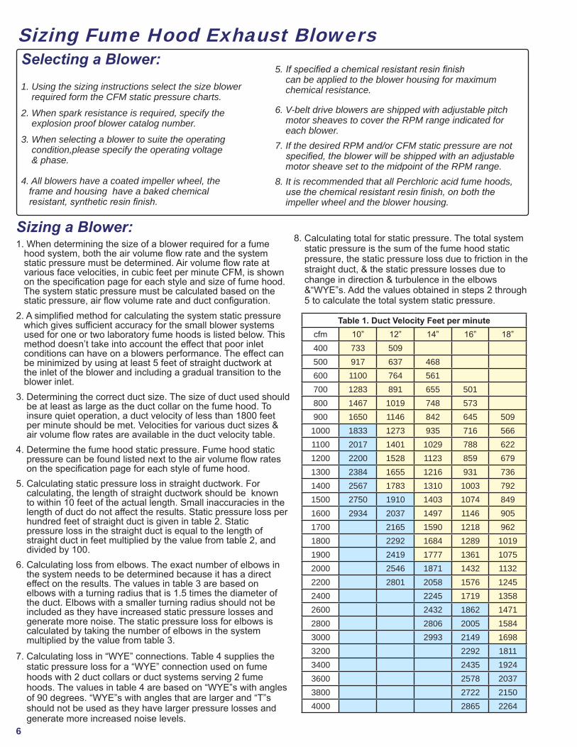
Sizing a Blower: 1. When determining the size of a blower required for a fume hood system, both the air volume flow rate and the system static pressure must be determined. Air volume flow rate at various face velocities, in cubic feet per minute CFM, is shown on the specification page for each style and size of fume hood. The system static pressure must be calculated based on the static pressure, air flow volume rate and duct configuration.2. A simplified method for calculating the system static pressure which gives sufficient accuracy for the small blower systems used for one or two laboratory fume hoods is listed below. This method doesn’t take into account the effect that poor inlet conditions can have on a blowers performance. The effect can be minimized by using at least 5 feet of straight ductwork at the inlet of the blower and including a gradual transition to the blower inlet.3. Determining the correct duct size. The size of duct used should be at least as large as the duct collar on the fume hood. To insure quiet operation, a duct velocity of less than 1800 feet per minute should be met. Velocities for various duct sizes & air volume flow rates are available in the duct velocity table.4. Determine the fume hood static pressure. Fume hood static pressure can be found listed next to the air volume flow rates on the specification page for each style of fume hood.5. Calculating static pressure loss in straight ductwork. For calculating, the length of straight ductwork should be known to within 10 feet of the actual length. Small inaccuracies in the length of duct do not affect the results. Static pressure loss per hundred feet of straight duct is given in table 2. Static pressure loss in the straight duct is equal to the length of straight duct in feet multiplied by the value from table 2, and divided by 100.6. Calculating loss from elbows. The exact number of elbows in the system needs to be determined because it has a direct effect on the results. The values in table 3 are based on elbows with a turning radius that is 1.5 times the diameter of the duct. Elbows with a smaller turning radius should not be included as they have increased static pressure losses and generate more noise. The static pressure loss for elbows is calculated by taking the number of elbows in the system multiplied by the value from table 3.7. Calculating loss in “WYE” connections. Table 4 supplies the static pressure loss for a “WYE” connection used on fume hoods with 2 duct collars or duct systems serving 2 fume hoods. The values in table 4 are based on “WYE”s with angles of 90 degrees. “WYE”s with angles that are larger and “T”s should not be used as they have larger pressure losses and generate more increased noise levels.
8. Calculating total for static pressure. The total system static pressure is the sum of the fume hood static pressure, the static pressure loss due to friction in the straight duct, & the static pressure losses due to change in direction & turbulence in the elbows &“WYE”s. Add the values obtained in steps 2 through 5 to calculate the total system static pressure.
Table 1. Duct Velocity Feet per minutecfm 10” 12” 14” 16” 18”400 733 509500 917 637 468600 1100 764 561700 1283 891 655 501800 1467 1019 748 573900 1650 1146 842 645 5091000 1833 1273 935 716 5661100 2017 1401 1029 788 6221200 2200 1528 1123 859 6791300 2384 1655 1216 931 7361400 2567 1783 1310 1003 7921500 2750 1910 1403 1074 8491600 2934 2037 1497 1146 9051700 2165 1590 1218 9621800 2292 1684 1289 10191900 2419 1777 1361 10752000 2546 1871 1432 11322200 2801 2058 1576 12452400 2245 1719 13582600 2432 1862 14712800 2806 2005 15843000 2993 2149 16983200 2292 18113400 2435 19243600 2578 20373800 2722 21504000 2865 2264
7
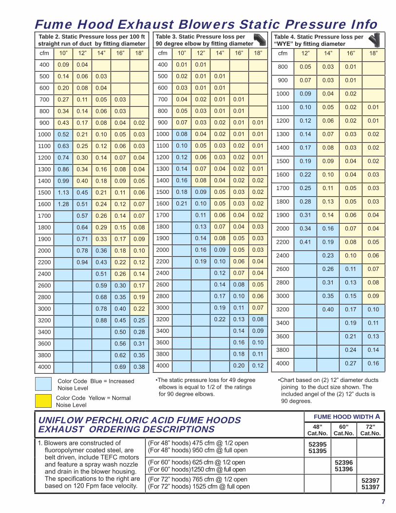
Fume Hood Exhaust Blowers Static Pressure InfoTable 2. Static Pressure loss per 100 ft straight run of duct by fitting diametercfm 10” 12” 14” 16” 18”
400 0.09 0.04
500 0.14 0.06 0.03
600 0.20 0.08 0.04
700 0.27 0.11 0.05 0.03
800 0.34 0.14 0.06 0.03
900 0.43 0.17 0.08 0.04 0.02
1000 0.52 0.21 0.10 0.05 0.03
1100 0.63 0.25 0.12 0.06 0.03
1200 0.74 0.30 0.14 0.07 0.04
1300 0.86 0.34 0.16 0.08 0.04
1400 0.99 0.40 0.18 0.09 0.05
1500 1.13 0.45 0.21 0.11 0.06
1600 1.28 0.51 0.24 0.12 0.07
1700 0.57 0.26 0.14 0.07
1800 0.64 0.29 0.15 0.08
1900 0.71 0.33 0.17 0.09
2000 0.78 0.36 0.18 0.10
2200 0.94 0.43 0.22 0.12
2400 0.51 0.26 0.14
2600 0.59 0.30 0.17
2800 0.68 0.35 0.19
3000 0.78 0.40 0.22
3200 0.88 0.45 0.25
3400 0.50 0.28
3600 0.56 0.31
3800 0.62 0.35
4000 0.69 0.38
Table 3. Static Pressure loss per 90 degree elbow by fitting diametercfm 10” 12” 14” 16” 18”
400 0.01 0.01
500 0.02 0.01 0.01
600 0.03 0.01 0.01
700 0.04 0.02 0.01 0.01
800 0.05 0.03 0.01 0.01
900 0.07 0.03 0.02 0.01 0.01
1000 0.08 0.04 0.02 0.01 0.01
1100 0.10 0.05 0.03 0.02 0.01
1200 0.12 0.06 0.03 0.02 0.01
1300 0.14 0.07 0.04 0.02 0.01
1400 0.16 0.08 0.04 0.02 0.02
1500 0.18 0.09 0.05 0.03 0.02
1600 0.21 0.10 0.05 0.03 0.02
1700 0.11 0.06 0.04 0.02
1800 0.13 0.07 0.04 0.03
1900 0.14 0.08 0.05 0.03
2000 0.16 0.09 0.05 0.03
2200 0.19 0.10 0.06 0.04
2400 0.12 0.07 0.04
2600 0.14 0.08 0.05
2800 0.17 0.10 0.06
3000 0.19 0.11 0.07
3200 0.22 0.13 0.08
3400 0.14 0.09
3600 0.16 0.10
3800 0.18 0.11
4000 0.20 0.12
Table 4. Static Pressure loss per “WYE” by fitting diameter
cfm 12” 14” 16” 18”
800 0.05 0.03 0.01
900 0.07 0.03 0.01
1000 0.09 0.04 0.02
1100 0.10 0.05 0.02 0.01
1200 0.12 0.06 0.02 0.01
1300 0.14 0.07 0.03 0.02
1400 0.17 0.08 0.03 0.02
1500 0.19 0.09 0.04 0.02
1600 0.22 0.10 0.04 0.03
1700 0.25 0.11 0.05 0.03
1800 0.28 0.13 0.05 0.03
1900 0.31 0.14 0.06 0.04
2000 0.34 0.16 0.07 0.04
2200 0.41 0.19 0.08 0.05
2400 0.23 0.10 0.06
2600 0.26 0.11 0.07
2800 0.31 0.13 0.08
3000 0.35 0.15 0.09
3200 0.40 0.17 0.10
3400 0.19 0.11
3600 0.21 0.13
3800 0.24 0.14
4000 0.27 0.16
Color Code Blue = Increased Noise Level
•The static pressure loss for 49 degree elbows is equal to 1/2 of the ratings for 90 degree elbows.
•Chart based on (2) 12” diameter ducts joining to the duct size shown. The included angel of the (2) 12” ducts is 90 degrees.
UNIFLOW PERCHLORIC ACID FUME HOODS EXHAUST ORDERING DESCRIPTIONS
FUME HOOD WIDTH A48”
Cat.No. 60”
Cat.No. 72”
Cat.No. 1. Blowers are constructed of fluoropolymer coated steel, are belt driven, include TEFC motors and feature a spray wash nozzle and drain in the blower housing. The specifications to the right are based on 120 Fpm face velocity.
(For 48” hoods) 475 cfm @ 1/2 open(For 48” hoods) 950 cfm @ full open
5239551395
(For 60” hoods) 625 cfm @ 1/2 open (For 60” hoods)1250 cfm @ full open
5239651396
(For 72” hoods) 765 cfm @ 1/2 open (For 72” hoods) 1525 cfm @ full open
5239751397
Color Code Yellow = Normal Noise Level
8
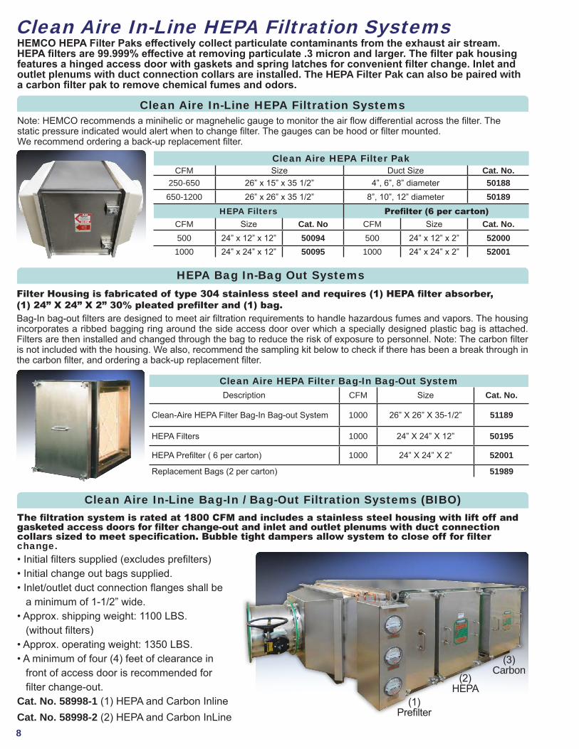
Filter Housing is fabricated of type 304 stainless steel and requires (1) HEPA filter absorber, (1) 24” X 24” X 2” 30% pleated prefilter and (1) bag. Bag-In bag-out filters are designed to meet air filtration requirements to handle hazardous fumes and vapors. The housing incorporates a ribbed bagging ring around the side access door over which a specially designed plastic bag is attached. Filters are then installed and changed through the bag to reduce the risk of exposure to personnel. Note: The carbon filter is not included with the housing. We also, recommend the sampling kit below to check if there has been a break through in the carbon filter, and ordering a back-up replacement filter.
Clean Aire In-Line HEPA Filtration SystemsHEMCO HEPA Filter Paks effectively collect particulate contaminants from the exhaust air stream. HEPA filters are 99.999% effective at removing particulate .3 micron and larger. The filter pak housing features a hinged access door with gaskets and spring latches for convenient filter change. Inlet and outlet plenums with duct connection collars are installed. The HEPA Filter Pak can also be paired with a carbon filter pak to remove chemical fumes and odors.
Clean Aire HEPA Filter PakCFM Size Duct Size Cat. No.
250-650 26” x 15” x 35 1/2” 4”, 6”, 8” diameter 50188650-1200 26” x 26” x 35 1/2” 8”, 10”, 12” diameter 50189
HEPA Filters Prefilter (6 per carton)CFM Size Cat. No CFM Size Cat. No.500 24” x 12” x 12” 50094 500 24” x 12” x 2” 52000
1000 24” x 24” x 12” 50095 1000 24” x 24” x 2” 52001
Note: HEMCO recommends a minihelic or magnehelic gauge to monitor the air flow differential across the filter. The static pressure indicated would alert when to change filter. The gauges can be hood or filter mounted. We recommend ordering a back-up replacement filter.
Clean Aire In-Line HEPA Filtration Systems
Clean Aire HEPA Filter Bag-In Bag-Out SystemDescription CFM Size Cat. No.
Clean-Aire HEPA Filter Bag-In Bag-out System 1000 26” X 26” X 35-1/2” 51189
HEPA Filters 1000 24” X 24” X 12” 50195
HEPA Prefilter ( 6 per carton) 1000 24” X 24” X 2” 52001
Replacement Bags (2 per carton) 51989
HEPA Bag In-Bag Out Systems
Clean Aire In-Line Bag-In / Bag-Out Filtration Systems (BIBO)
• Initial filters supplied (excludes prefilters)• Initial change out bags supplied.• Inlet/outlet duct connection flanges shall be a minimum of 1-1/2” wide.• Approx. shipping weight: 1100 LBS. (without filters)• Approx. operating weight: 1350 LBS.• A minimum of four (4) feet of clearance in front of access door is recommended for filter change-out. Cat. No. 58998-1 (1) HEPA and Carbon InlineCat. No. 58998-2 (2) HEPA and Carbon InLine
The filtration system is rated at 1800 CFM and includes a stainless steel housing with lift off and gasketed access doors for filter change-out and inlet and outlet plenums with duct connection collars sized to meet specification. Bubble tight dampers allow system to close off for filter change.
(1) Prefilter
(2) HEPA
(3) Carbon
9
Clean Aire In-Line Carbon Filtration Systems
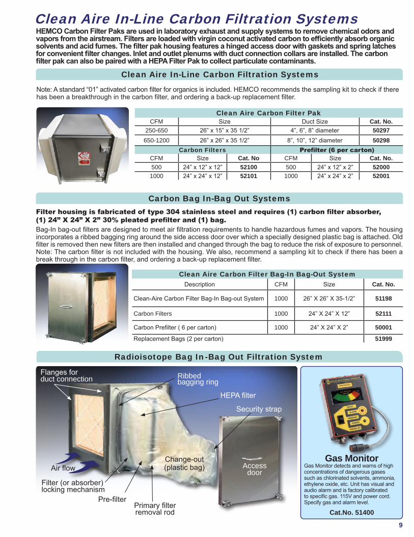
Gas MonitorGas Monitor detects and warns of high concentrations of dangerous gases such as chlorinated solvents, ammonia, ethylene oxide, etc. Unit has visual and audio alarm and is factory calibrated to specific gas. 115V and power cord. Specify gas and alarm level.
Cat.No. 51400
Radioisotope Bag In-Bag Out Filtration System
Access door
Security strap
HEPA filter
Ribbed bagging ring
Flanges for duct connection
Air flow
Filter (or absorber)locking mechanism
Primary filterremoval rod
Pre-filter
Change-out(plastic bag)
HEMCO Carbon Filter Paks are used in laboratory exhaust and supply systems to remove chemical odors and vapors from the airstream. Filters are loaded with virgin coconut activated carbon to efficiently absorb organic solvents and acid fumes. The filter pak housing features a hinged access door with gaskets and spring latches for convenient filter changes. Inlet and outlet plenums with duct connection collars are installed. The carbon filter pak can also be paired with a HEPA Filter Pak to collect particulate contaminants.
Clean Aire Carbon Filter PakCFM Size Duct Size Cat. No.
250-650 26” x 15” x 35 1/2” 4”, 6”, 8” diameter 50297650-1200 26” x 26” x 35 1/2” 8”, 10”, 12” diameter 50298
Carbon Filters Prefilter (6 per carton)CFM Size Cat. No CFM Size Cat. No.500 24” x 12” x 12” 52100 500 24” x 12” x 2” 52000
1000 24” x 24” x 12” 52101 1000 24” x 24” x 2” 52001
Carbon Bag In-Bag Out SystemsFilter housing is fabricated of type 304 stainless steel and requires (1) carbon filter absorber, (1) 24” X 24” X 2” 30% pleated prefilter and (1) bag. Bag-In bag-out filters are designed to meet air filtration requirements to handle hazardous fumes and vapors. The housing incorporates a ribbed bagging ring around the side access door over which a specially designed plastic bag is attached. Old filter is removed then new filters are then installed and changed through the bag to reduce the risk of exposure to personnel. Note: The carbon filter is not included with the housing. We also, recommend a sampling kit to check if there has been a break through in the carbon filter, and ordering a back-up replacement filter.
Clean Aire Carbon Filter Bag-In Bag-Out SystemDescription CFM Size Cat. No.
Clean-Aire Carbon Filter Bag-In Bag-out System 1000 26” X 26” X 35-1/2” 51198
Carbon Filters 1000 24” X 24” X 12” 52111
Carbon Prefilter ( 6 per carton) 1000 24” X 24” X 2” 50001
Replacement Bags (2 per carton) 51999
Note: A standard “01” activated carbon filter for organics is included. HEMCO recommends the sampling kit to check if there has been a breakthrough in the carbon filter, and ordering a back-up replacement filter.
Clean Aire In-Line Carbon Filtration Systems
10
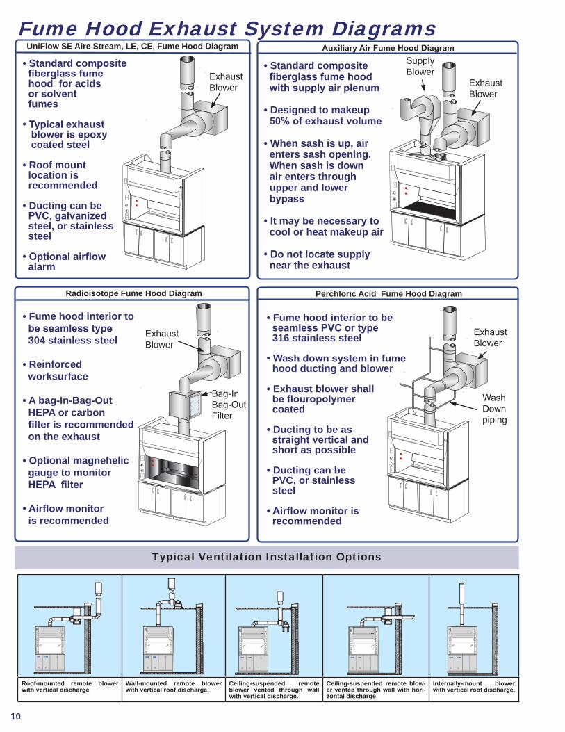
Fume Hood Exhaust System Diagrams
Radioisotope Fume Hood Diagram Perchloric Acid Fume Hood Diagram
Auxiliary Air Fume Hood Diagram
• Standard composite fiberglass fume hood for acids or solvent fumes
• Typical exhaust blower is epoxy coated steel
• Roof mount location is recommended
• Ducting can be PVC, galvanized steel, or stainless steel
• Optional airflow alarm
UniFlow SE Aire Stream, LE, CE, Fume Hood Diagram
Typical Ventilation Installation Options
Roof-mounted remote blower with vertical discharge
Wall-mounted remote blower with vertical roof discharge.
Ceiling-suspended remote blower vented through wall with vertical discharge.
Ceiling-suspended remote blow-er vented through wall with hori-zontal discharge
Internally-mount blower with vertical roof discharge.
Exhaust Blower
• Standard composite fiberglass fume hood with supply air plenum
• Designed to makeup 50% of exhaust volume
• When sash is up, air enters sash opening. When sash is down air enters through upper and lower bypass
• It may be necessary to cool or heat makeup air
• Do not locate supply near the exhaust
Exhaust Blower
SupplyBlower
• Fume hood interior to be seamless type 304 stainless steel
• Reinforced worksurface
• A bag-In-Bag-Out HEPA or carbon filter is recommended on the exhaust
• Optional magnehelic gauge to monitor HEPA filter
• Airflow monitor is recommended
Exhaust Blower
Bag-InBag-Out Filter
• Fume hood interior to be seamless PVC or type 316 stainless steel
• Wash down system in fume hood ducting and blower
• Exhaust blower shall be flouropolymer coated
• Ducting to be as straight vertical and short as possible
• Ducting can be PVC, or stainless steel
• Airflow monitor is recommended
Exhaust Blower
Wash Down piping
11
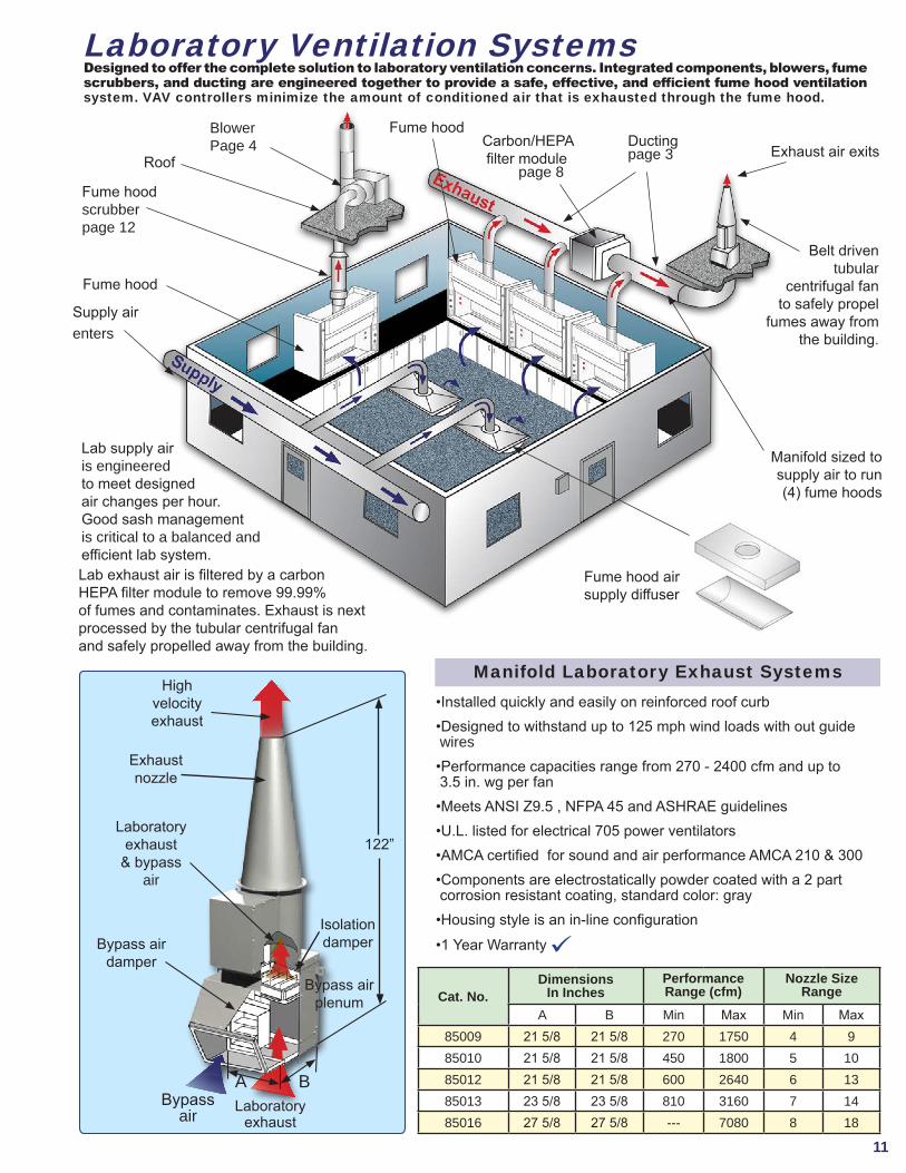
Laboratory Ventilation Systems
Lab supply air is engineered to meet designed air changes per hour. Good sash management is critical to a balanced and efficient lab system.
Belt driven tubular
centrifugal fan to safely propel
fumes away from the building.
Fume hood scrubberpage 12
Fume hood
Fume hood Carbon/HEPA filter module page 8
Fume hood air supply diffuser
Designed to offer the complete solution to laboratory ventilation concerns. Integrated components, blowers, fume scrubbers, and ducting are engineered together to provide a safe, effective, and efficient fume hood ventilation system. VAV controllers minimize the amount of conditioned air that is exhausted through the fume hood.
Roof
Lab exhaust air is filtered by a carbon HEPA filter module to remove 99.99% of fumes and contaminates. Exhaust is next processed by the tubular centrifugal fanand safely propelled away from the building.
Supply airenters
Exhaust air exits
Cat. No.Dimensions
In InchesPerformance Range (cfm)
Nozzle Size Range
A B Min Max Min Max85009 21 5/8 21 5/8 270 1750 4 985010 21 5/8 21 5/8 450 1800 5 1085012 21 5/8 21 5/8 600 2640 6 1385013 23 5/8 23 5/8 810 3160 7 1485016 27 5/8 27 5/8 --- 7080 8 18
•Installed quickly and easily on reinforced roof curb•Designed to withstand up to 125 mph wind loads with out guide wires•Performance capacities range from 270 - 2400 cfm and up to 3.5 in. wg per fan •Meets ANSI Z9.5 , NFPA 45 and ASHRAE guidelines•U.L. listed for electrical 705 power ventilators•AMCA certified for sound and air performance AMCA 210 & 300•Components are electrostatically powder coated with a 2 part corrosion resistant coating, standard color: gray•Housing style is an in-line configuration•1 Year Warranty
Manifold Laboratory Exhaust Systems
Bypassair
Bypass air damper
Laboratoryexhaust
& bypass air
Exhaustnozzle
High velocity exhaust
Laboratoryexhaust
A B
Isolation damper
122”
Bypass air plenum
BlowerPage 4 Ducting
page 3
Manifold sized to supply air to run (4) fume hoods
12
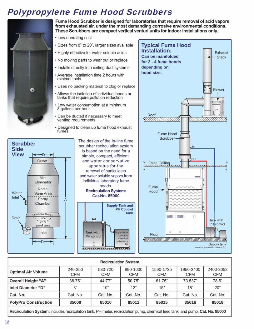
Polypropylene Fume Hood Scrubbers
• Low operating cost
• Sizes from 8” to 20”, larger sizes available
• Highly effective for water soluble acids
• No moving parts to wear out or replace
• Installs directly into exiting duct systems
• Average installation time 2 hours with minimal tools
• Uses no packing material to clog or replace
• Allows the isolation of individual hoods or tanks that require pollution reduction
• Low water consumption at a minimum 8 gallons per hour
• Can be ducted if necessary to meet venting requirements
• Designed to clean up fume hood exhaust fumes.
Fume Hood Scrubber is designed for laboratories that require removal of acid vapors from exhausted air, under the most demanding corrosive environmental conditions. These Scrubbers are compact vertical venturi units for indoor installations only.
Recirculation System
Optimal Air Volume 240-250CFM
580-720CFM
890-1000CFM
1590-1735CFM
1950-2400CFM
2400-3052CFM
Overall Height “A” 38.75” 44.77” 50.75” 61.75” 73.537” 78.5”Inlet Diameter “D” 8” 10” 12” 15” 18” 20”
Cat. No. Cat. No. Cat. No. Cat. No. Cat. No. Cat. No. Cat. No.
PolyPro Construction 85008 85010 85012 85015 85016 85018
Recirculation System: includes recirculation tank, PH meter, recirculation pump, chemical feed tank, and pump. Cat. No. 85000
D
D
A
Water Inlet
Drain
Mist Eliminator
Radial Vane Area
Spray Chamber
Upper Sump
Lower Sump
Inlet
Outlet
Directional Baf es
The design of the In-line fume scrubber recirculation system
is based on the need for a simple, compact, efficient, and water conservative
apparatus for theremoval of particulates
and water soluble vapors from individual laboratory fume
hoods. Recirculation System:
Cat.No. 85000
Tank with PH control
Supply tankcontains chemical
to balance PH
Supply Tank and PH Control
Tank
Scrubber Side View
Floor
Fume Hood
False Ceiling
Fume HoodScrubber
Roof
Exhaust Stack
Blower
Supply tank(contains chemical to balance PH)
In
Out
Tank with PH control
Typical Fume HoodInstallation:Can be manifolded for 2 - 4 fume hoodsdepending on hood size.
STORAGEACID
visit www.HEMCOcorp.com
STORAGEACID
visit www.HEMCOcorp.com
13
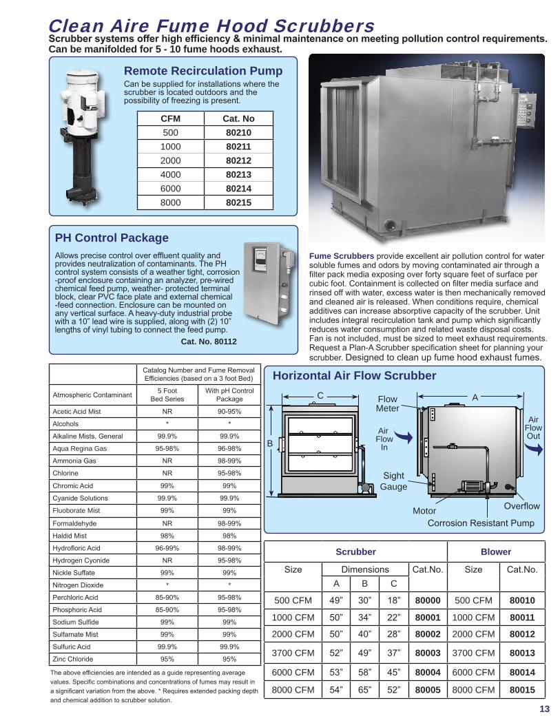
Scrubber systems offer high efficiency & minimal maintenance on meeting pollution control requirements.Can be manifolded for 5 - 10 fume hoods exhaust.
Remote Recirculation PumpCan be supplied for installations where the scrubber is located outdoors and thepossibility of freezing is present.
CFM Cat. No500 802101000 802112000 802124000 802136000 802148000 80215
PH Control PackageAllows precise control over efuent quality and provides neutralization of contaminants. The PH control system consists of a weather tight, corrosion -proof enclosure containing an analyzer, pre-wired chemical feed pump, weather- protected terminal block, clear PVC face plate and external chemical -feed connection. Enclosure can be mounted on any vertical surface. A heavy-duty industrial probe with a 10” lead wire is supplied, along with (2) 10” lengths of vinyl tubing to connect the feed pump. Cat. No. 80112
Scrubber Blower
Size Dimensions Cat.No. Size Cat.No.A B C
500 CFM 49” 30” 18” 80000 500 CFM 80010
1000 CFM 50” 34” 22” 80001 1000 CFM 80011
2000 CFM 50” 40” 28” 80002 2000 CFM 80012
3700 CFM 52” 49” 37” 80003 3700 CFM 80013
6000 CFM 53” 58” 45” 80004 6000 CFM 80014
8000 CFM 54” 65” 52” 80005 8000 CFM 80015
Fume Scrubbers provide excellent air pollution control for water soluble fumes and odors by moving contaminated air through a filter pack media exposing over forty square feet of surface per cubic foot. Containment is collected on filter media surface and rinsed off with water, excess water is then mechanically removed and cleaned air is released. When conditions require, chemical additives can increase absorptive capacity of the scrubber. Unit includes integral recirculation tank and pump which significantly reduces water consumption and related waste disposal costs. Fan is not included, must be sized to meet exhaust requirements. Request a Plan-A Scrubber specification sheet for planning your scrubber. Designed to clean up fume hood exhaust fumes.
Catalog Number and Fume Removal Efficiencies (based on a 3 foot Bed)
Atmospheric Contaminant 5 Foot Bed Series
With pH ControlPackage
Acetic Acid Mist NR 90-95%
Alcohols * *
Alkaline Mists, General 99.9% 99.9%
Aqua Regina Gas 95-98% 96-98%
Ammonia Gas NR 98-99%
Chlorine NR 95-98%
Chromic Acid 99% 99%
Cyanide Solutions 99.9% 99.9%
Fluoborate Mist 99% 99%
Formaldehyde NR 98-99%
Haldid Mist 98% 98%
Hydrofloric Acid 96-99% 98-99%
Hydrogen Cyonide NR 95-98%
Nickle Suffate 99% 99%
Nitrogen Dioxide * *
Perchloric Acid 85-90% 95-98%
Phosphoric Acid 85-90% 95-98%
Sodium Sulfide 99% 99%
Sulfamate Mist 99% 99%
Sulfuric Acid 99.9% 99.9%
Zinc Chloride 95% 95%
C
B
AFlow Meter
Sight Gauge
MotorCorrosion Resistant Pump
Overflow
Air Flow
In
Air Flow Out
Horizontal Air Flow Scrubber
The above efficiencies are intended as a guide representing average values. Specific combinations and concentrations of fumes may result in a significant variation from the above. * Requires extended packing depth and chemical addition to scrubber solution.
Clean Aire Fume Hood Scrubbers
14
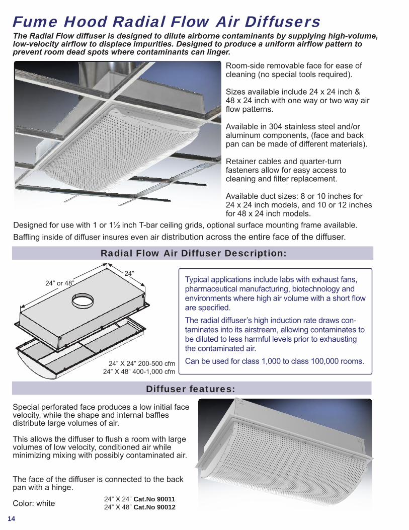
Fume Hood Radial Flow Air DiffusersThe Radial Flow diffuser is designed to dilute airborne contaminants by supplying high-volume,low-velocity airflow to displace impurities. Designed to produce a uniform airflow pattern to prevent room dead spots where contaminants can linger.
Room-side removable face for ease of cleaning (no special tools required).
Sizes available include 24 x 24 inch & 48 x 24 inch with one way or two way air flow patterns.
Available in 304 stainless steel and/or aluminum components, (face and back pan can be made of different materials).
Retainer cables and quarter-turn fasteners allow for easy access to cleaning and filter replacement.
Available duct sizes: 8 or 10 inches for 24 x 24 inch models, and 10 or 12 inches for 48 x 24 inch models.
Special perforated face produces a low initial face velocity, while the shape and internal bafes distribute large volumes of air.
This allows the diffuser to flush a room with large volumes of low velocity, conditioned air while minimizing mixing with possibly contaminated air.
The face of the diffuser is connected to the back pan with a hinge.
Color: white
Diffuser features:
Radial Flow Air Diffuser Description:
Typical applications include labs with exhaust fans, pharmaceutical manufacturing, biotechnology and environments where high air volume with a short flow are specified. The radial diffuser’s high induction rate draws con-taminates into its airstream, allowing contaminates to be diluted to less harmful levels prior to exhausting the contaminated air. Can be used for class 1,000 to class 100,000 rooms.24” X 24” 200-500 cfm
24” X 48” 400-1,000 cfm
24” X 24” Cat.No 9001124” X 48” Cat.No 90012
24”24” or 48”
Designed for use with 1 or 1½ inch T-bar ceiling grids, optional surface mounting frame available.Bafing inside of diffuser insures even air distribution across the entire face of the diffuser.

15
VAV Variable Air Volume Systems
Pressure-independent air valves maintain proper flows over the entire range of command. Sash opening determines flow requirements through the hood while the room make-up air is adjusted to maintain proper pressurization. When additional air is required due to ventilation or thermal requirements, the general exhaust and make-up air valves adjust to requirements. Fume hood monitor provides continuous monitoring of air volume, to meet regulatory requirements.
• Fast flow control with, stable adjustments over large flow changes.
• Minimal maintenance required.• Pressure independent system maintains steady flow through air changes, HYAC degradation, and filter loading, eliminating the need for re-balancing.• Sound power levels remain low.• Valves used in variable volume systems provide the benefits listed above, although, the disadvantages of not closing sashes still remain.
Variable Air Volume with UBC (usage based controls) provides an intelligent form of variable volume control for fumehoods. UBC eliminates the disadvantages of not closing sashes, but still maintains safe face velocity lev-els while minimizing the HVAC burden. The concept is: use a higher face velocity when an operator is in front of the hood creating turbulence, but reduce the air flow to a safe level when operator is not using the fume hood. Figure 2 represents a typical UBC system. Room pres-sure is maintained by adjusting the make up air at a lower rate than the exhaust. Minimum ventilation and proper temperature control may require the use of a general exhaust valve, where the exhaust air rate is increased to overcome the added supply requirements.
• The hood operates at the lowest flow possible to maintain safe face velocities. • When a user approaches the hood, the zone presence sensor increases the flow to provide proper containment. • As the user exits the hood, the flow is reset to the lower, yet safe, flow. The fume hood monitor provides continuous air flow monitoring.
• Sizing of mechanical equipment based on partial load-is improved.• HVAC costs are reduced, by assuring reductions in airflow, even when sashes are left open.• Lower energy costs.• Lab safety is improved due to the reduction in supply air currents that often affect fume hood containment.
Pressure Sensor
Sash Sensor Venturi
Valve
Fume Hood Monitor
Detection Zone
Figure 1 Variable air volume application with controls.
Figure 2 Variable volume application with Usage Based Controls.
HEMCO offers sash sensing, pressure independent venturi air valves, & volumetric room flow controls for YAYapplications. figure1 shows a lab with variableair volume components.
T
VAV Makeup Air
Offset 100 CFM
Supply 100-900 CFM
VAV Fume Hood
VAV General Exhaust Exhaust
200-1000 CFM
Supply Air
Exhaust Air
Room Supply Air

HEMCO Corporation711 S. Powell RoadIndependence, MO 64056
Most Extensive Line of Laboratory Fume Hoods in the Industry Reduce Energy costs up to 50% with HEMCO Sash Management 1-2-3,
which provides maximum energy efficiency and user protection.
Laboratory Fume Hoods are available in 1. Constant Air Volume CAV Air By-Pass 2. Variable Air Volume VAV Restricted Bypass 3. Explosion Proof models for Hazardous Locations 4. CE models for International Electronic Configurations Standard Bench Mount and Floor Mount hoods with over 40 standard sizes and custom sizes to your specs. UniFlow Superstructure exclusive unitized dual wall construction for total chemical resistance, strength, and durability. Performance tested to ASHRAE 110 - 1995. U.L.1805 Classified for Fume Hoods & Cabinets, and SEFA1 Recommended Practices for Fume Hoods.
Specify UniFlow Fume HoodsSpecify UniFlow Fume Hoods on Your Next Lab Project on Your Next Lab Project
UniFlowUniFlow
Phone (816) 796-2900www.HEMCOcorp.com
VENT-02.20
1805
Made inU.S.A.
Request a free brochure At www.HEMCOcorp.com and browse the entire selection of HEMCO Laboratory Equipment
Scientific Equipment and Furniture Association
R
HEMCOLaboratory Planning Solutions
®
Lab Planning Solutions Complete Laboratory
Planning Guide
Modular Clean Labs& Quality Control Labs
Brochure
UniMax LargeFloor Mount Walk-In
Fume Hoods Brochure
EnviroMax Enclosures for Robotic and Automated
Lab Processes