
LAB MANUAL - vvitengineeringvvitengineering.com/lab/EE6411-ELECTRICAL-MACHINES... · In general...
69
EE6411- ELECTRICAL MACHINES I 1 VVIT – DEPARTMENT OF EEE Dharmapuri – 636 703 Regulation : 2013 Branch : B.E - EEE Year & Semester : II Year / IV Semester EE6411- ELECTRICAL MACHINES LABORATORY I LAB MANUAL
Transcript of LAB MANUAL - vvitengineeringvvitengineering.com/lab/EE6411-ELECTRICAL-MACHINES... · In general...

EE6411- ELECTRICAL MACHINES I 1
VVIT – DEPARTMENT OF EEE
Dharmapuri – 636 703
Regulation : 2013
Branch : B.E - EEE
Year & Semester : II Year / IV Semester
EE6411- ELECTRICAL MACHINES LABORATORY I
LAB MANUAL

EE6411- ELECTRICAL MACHINES I 2
VVIT – DEPARTMENT OF EEE
ANNA UNIVERSITY- CHENNAI
2013 -REGULATION
EE6411 - ELECTRICAL MACHINES LABORATORY – I
LIST OF EXPERIMENTS:
1. Open circuit and load characteristics of DC shunt generator- critical resistance and
critical speed.
2. Load characteristics of DC compound generator with differential and
cumulativeconnections.
3. Load test on DC shunt and compound motor.
4. Load test on DC series motor.
5. Swinburne’s test and speed control of DC shunt motor.
6. Hopkinson’s test on DC motor – generator set.
7. Load test on single-phase transformer and three phase transformers.
8. Open circuit and short circuit tests on single phase transformer.
9. Polarity Test and Sumpner’s test on single phase transformers.
10. Separation of no-load losses in single phase transformer.
11.Study of starters and 3-phase transformers connections
TOTAL: 45 PERIODS

EE6411- ELECTRICAL MACHINES I 3
VVIT – DEPARTMENT OF EEE
SAFETY PRECAUTIONSPRIMARY RULES:
Do not make circuit changes or perform any wiring when power is on. When in doubt, turn power off.
Assume that panel jacks on your bench are electrically live unless power is off. Be sure you understand the function and wiring of an instrument before using it in a
circuit.
Do not repeat the same mistake. Do not wear loose-fitting clothing or jewelry in the lab. Rings and necklaces are usually
excellent conductors in excellent contact with your skin.
It is wise in electrical labs to wear pants rather than shorts or skirts. Ties are alsodangerous.
Powered equipment can be hot! Use caution when handling equipment after it has beenoperating.
ADDITIONAL KEY PRECAUTIONS:
Check yourself with disconnect switches, especially those at your bench. Work slowly and deliberately. Think as you act.
Do your wiring, setup, and a careful circuit checkout before applying power. Use wires of appropriate length. Do not allow them to drape over your equipment.
Avoid splices, which create live surfaces. When running a pair of wires to adjacentterminals, twist the wires together so they do not dangle. This also neatens your workand will save time.
Keep your bench organized and neat. It should be clear of coats, extra books andpapers, and unused equipment.
Use your bench. Avoid long connections by using the bench transfer wires. Pluginstruments into the bench, not into the wall. This gives you the protection of the benchswitches.
Do not touch anything if your hands are wet. The “one-hand” approach is safest. Do not pull wires out until you are absolutely sure that the circuit is completely dead.
Shocks can occur if an inductive load (motor or transformer) is disconnected whileconducting.

EE6411- ELECTRICAL MACHINES I 4
VVIT – DEPARTMENT OF EEE
ELECTRICAL MACHINES
INTRODUCTION:
The study of electric machinery and electromechanics offers a wide range ofopportunities in such diverse areas as manufacturing process control, control systems,electrical energy generation, electromechanical systems and actuators, electric and hybridtransportation, disk drives, electronic power conversion, and others.
Electric machinery and electro mechanics provides an area for the generalist, in thatexpertise in electromagnetic field theory, circuit analysis, communication principles,information theory, electronics, computers, control systems, and energy areas must cometogether to create a complete working system. The study of electric machinery is longestablished within electrical engineering. New technologies and materials, the economics ofenergy, the use of sophisticated computer hardware and software, and rapid advances inpower electronics for energy and motion control offer inviting topics for new engineers.
CLASSIFICATIONS:
In general electrical machines is classified into two types, they are Motor Generator
Both Motor and generator are three types, Shunt Series
CompoundShunt:
Armature and field winding are in parallel connectionSeries:
Armature and field winding are in series connectionCompound:
It is combination of both series and shunt type.
In electrical engineering, electric machine is a general term for electricmotors and electric generators. They are electromechanical energy converters.
Electric motor:It converts electrical energy into mechanical energy
Electric generator:It converts mechanical energy to electrical energy
Transformers:It is a static device, which is used to convert voltag

EE6411- ELECTRICAL MACHINES I 5
VVIT – DEPARTMENT OF EEE
INDEX
S.NO DATE LIST OF THE EXPERIMENTSIGNATURE
OF THESTAFF
REMARKS
1 Load test on DC shunt motor
2 Load test on DC series motor
3 Speed control of DC shunt motor
4OCC & load test on separatelyexcited DC generator
5OCC & load test on self-excitedDC generator
6Load test on single phasetransformer
7OC & SC test on single phasetransformer
8 Swinburne’s test
9Separation of iron losses in DCmachine
10 Hopkinson’s test
11 Sumpner’s test
12Study of three phase transformerconnections
13 Load test on DC compound motor
14Load test on DC compoundgenerator

EE6411- ELECTRICAL MACHINES I 6
VVIT – DEPARTMENT OF EEE
AIM:
To conduct load test on D.C motor and to obtain performance characteristics
APPARATUS REQUIRED:
S. No. Apparatus Type Range Quantity
1 Voltmeter MC (0-300)V 1
2 Ammeter MC (0-20)A 1
3 Rheostat 230 Ω /1.5A 1
4 Tachometer Digital 60,000RPM 1
FUSE RATING:
125% of rated current
PRECAUTIONS:
The motor field rheostat should be kept at minimum resistance position.
The motor should be started at no load condition.
The motor should be cooled by circulating water throughout the experiment.
PROCEDURE:
1. Connect as per the circuit diagram.2. Close the DPSTswitch.3. Stat the motor using three point starter.4.Adjust the field rheostat till the motor reaches its rated speed.
5. Note down the no load reading of voltmeter, ammeter, speed and springbalance reading.
6. Apply load in steps and note down the corresponding reading till the ratedcurrent is reached rated value.
.
EX.NO. 1LOAD TEST ON D.C. SHUNT MOTOR
DATE:

EE6411- ELECTRICAL MACHINES I 7
VVIT – DEPARTMENT OF EEE
CIRCUIT DIAGRAM ( LOAD TEST ON DC SHUNT MOTOR):

EE6411- ELECTRICAL MACHINES I 8
VVIT – DEPARTMENT OF EEE
TABULATION: (LOAD TEST ON D.C. SHUNT MOTOR)
S. No
VoltageV
volts
CurrentI
amps
Springbalancereadings
S1~ S2
Kg
SpeedN
rpm
TorqueT
Nm
Inputpower
Pi
watts
OutputPower
Pm
watts
Efficiency
%S1
Kg
S2
Kg

EE6411- ELECTRICAL MACHINES I 9
VVIT – DEPARTMENT OF EEE
MODEL GRAPHS:
Spee
d N
(rpm
)
Torq
ue T
(Nm
)
Effic
ienc
y % N
T
y3 y2 y1
Output Power (Watts)
Spee
d N
(rpm
)
y
x
Torque T (Nm)

EE6411- ELECTRICAL MACHINES I 10
VVIT – DEPARTMENT OF EEE
FORMULAE:
Torque (T) = 9.81(s1s2)R Output power = 2ΠNT/60 Input power = V*I
Where,
9.81 = gravity constant
R = radius of brake drum
N = speed in RPM
RESULT:
Thus the load test on DCshunt motor was performed and the performancegraphs were drawn.
Efficiency , %=output power/input power * 100

EE6411- ELECTRICAL MACHINES I 11
VVIT – DEPARTMENT OF EEE
EX.NO. 2LOAD TEST ON D.C. SERIES MOTOR
DATE:
AIM:
To conduct load test on D.C series motor and to obtain performancecharacteristics
APPARATUS REQUIRRED:
S. No. Apparatus Type Range Quantity
1 Voltmeter MC (0-300)V 12 Ammeter MC (0-20)A 13 Tachometer Digital 60,000RPM 1
FUSE RATING:
125% of rated current
PRECAUTIONS:
The motor field rheostat should be kept at minimum resistance position.
The motor should be started at no load condition.
The motor should be cooled by circulating water throughout the experiment.
PROCEDURE:
1. Connect as per the circuit diagram.2. Close the DPST switch.3. Stat the motor using three point starter.4.Adjust the field rheostat till the motor reaches its rated speed.
5. Note down the no load reading of voltmeter, ammeter, speed and springbalance reading.
6. Apply load in steps and note down the corresponding reading till the ratedcurrent is reached rated value.

EE6411- ELECTRICAL MACHINES I 12
VVIT – DEPARTMENT OF EEE
CIRCUIT DIAGRAM ( LOAD TEST ON DC SERIES MOTOR):

EE6411- ELECTRICAL MACHINES I 13
VVIT – DEPARTMENT OF EEE
TABULATION (LOAD TEST ON DC SERIES MOTOR):
S. No
VoltageV
volts
CurrentI
amps
Springbalancereadings
S1~ S2
Kg
SpeedN
rpm
TorqueT
Nm
Inputpower
Pi
watts
OutputPower
Pm
watts
Efficiency
%S1
Kg
S2
Kg
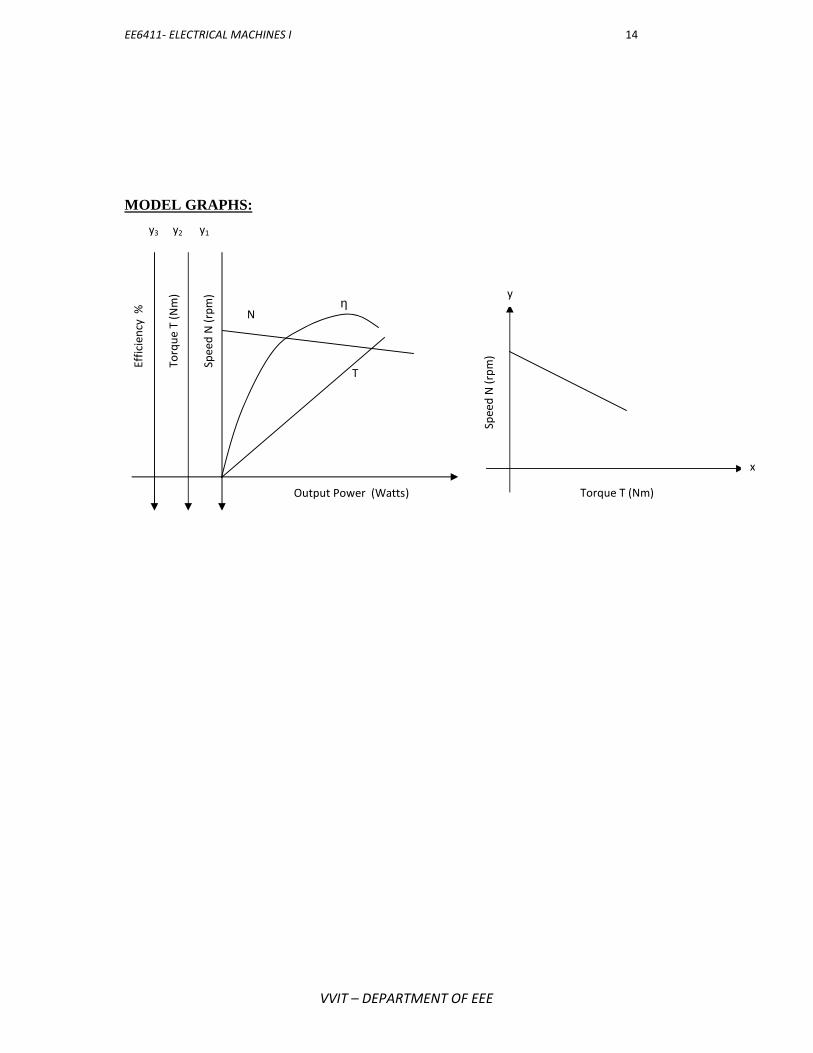
EE6411- ELECTRICAL MACHINES I 14
VVIT – DEPARTMENT OF EEE
MODEL GRAPHS:Sp
eed
N (r
pm)
Torq
ue T
(Nm
)
Effic
ienc
y % N
T
y3 y2 y1
Output Power (Watts)Sp
eed
N (r
pm)
y
x
Torque T (Nm)

EE6411- ELECTRICAL MACHINES I 15
VVIT – DEPARTMENT OF EEE
FORMULAE:
Torque (T) = 9.81(s1s2)R Output power = 2ΠNT/60 Input power = V*I
Where,
9.81 = gravity constant
R = radius of brake drum
N = speed in RPM
RESULT:
Thus the load test on DC series motor was performed and the performancegraphs were drawn.
Efficiency , %=output power/input power * 100

EE6411- ELECTRICAL MACHINES I 16
VVIT – DEPARTMENT OF EEE
EX.NO. 3SPEED CONTROL OF DC SHUNT MOTOR
DATE:
AIM:
To control the speed of DC shunt motor by Armature control method andField control method
APPARATUS REQUIRRED:
S. No. Apparatus Type Range Quantity
1 Voltmeter MC (0-300)V 1
2 Ammeter MC (0-20)A 1
3 Rheostat1250Ω/0.8A,50Ω/3.5A 2
4 Tachometer Digital 60000RPM 1
FUSE RATING:
40% of rated current
PRECAUTIONS:
Armature rheostat must be kept at maximum resistance position. Field rheostat should be kept at minimum resistance minimum position.
PROCEDURE:
ARMATURE CONTROL METHOD:
1. Connect as per the circuit diagram.2. Close the DPST switch.3. Start the motor using three point starter.4. By keeping the field current(If) as constant value, adjust the armature
rheostat and note down the corresponding armature voltage and motorspeed.
5. Repeat the step four till the motor reaches the rated speed.

EE6411- ELECTRICAL MACHINES I 17
VVIT – DEPARTMENT OF EEE
FLUX CONTROL METHOD:
1. Connect as per the circuit diagram.2. Close the DPST switch.3. Start the motor using three point starter.4. By keeping the armature voltage as constant value, adjust the field rheostat
and note down corresponding field current and motor speed5. Repeat the step four till the motor reaches the rated speed

EE6411- ELECTRICAL MACHINES I 18
VVIT – DEPARTMENT OF EEE
CIRCUIT DIAGRAM (SPEED CONTROL DC SHUNT MOTOR):
EE6411- ELECTRICAL MACHINES I 18
VVIT – DEPARTMENT OF EEE
CIRCUIT DIAGRAM (SPEED CONTROL DC SHUNT MOTOR):
EE6411- ELECTRICAL MACHINES I 18
VVIT – DEPARTMENT OF EEE
CIRCUIT DIAGRAM (SPEED CONTROL DC SHUNT MOTOR):

EE6411- ELECTRICAL MACHINES I 19
VVIT – DEPARTMENT OF EEE
MODEL GRAPHS:
Spee
d N
(rpm
)
Spee
d N
(rpm
)
If (Amps)Va (Volts)
If1
If3
If2
Va3
Va1
Va2

EE6411- ELECTRICAL MACHINES I 20
VVIT – DEPARTMENT OF EEE
TABULATION:
ARMATURE CONTROL METHOD:
S.NO
Field current ,If =___________A Field current ,If =___________A
Armature voltageVa
volts
SpeedN
RPM
Armature voltageVa
volts
SpeedN
RPM
FIELD CONTROL METHOD:
S.NO
Armature voltage, Va =___________V Armature voltage, Va =___________V
Field currentIf
Amps
SpeedN
RPM
Field currentIf
Amps
SpeedN
RPM

EE6411- ELECTRICAL MACHINES I 21
VVIT – DEPARTMENT OF EEE
RESULT:
Thus the speed of DC shunt motor was controlled by Armature control methodandField control method and the respective graphs were drawn.

EE6411- ELECTRICAL MACHINES I 22
VVIT – DEPARTMENT OF EEE
EX.NO. 4 OCC & LOAD TEST ON SEPERATELY EXCITED DCGENERATOR
DATE:
AIM:
To conduct OCC and load test of a separately excited DC generator andto plot the internal and external characteristics.
APPARATUS REQUIRRED:
S. No. Apparatus Type Range Quantity
1 Voltmeter MC (0-300)V 1
2 Ammeter MC (0-20)A,(0-2)A 2
3 Rheostat 1250Ω,0.8A 1
4 Tachometer Digital 60000RPM 1
FUSE RATING:
125% of rated current
PRECAUTIONS:
Field rheostat of motor should be kept at minimum resistance position. Field rheostat of generator should be kept at minimum resistance position.
PROCEDURE:
OC TEST:1. Connect as per the circuit diagram.2. Close the DPST switch.3. Start the motor using three point starter.4. By keeping the field current (If) as constant value, adjust the armature
rheostat and note down the corresponding armature voltage and motorspeed.
5. Adjust the potential divider and note down ammeter and voltmeterreadings.
LOAD TEST:1. Connect as per the circuit diagram.2. Close the DPST switch.3. Start the motor using three point starter.4. By keeping the armature voltage as constant value, adjust the field rheostat
and note down corresponding field current and motor speed.5.Adjust the potential divider and note down ammeter and voltmeter readings

EE6411- ELECTRICAL MACHINES I 23
VVIT – DEPARTMENT OF EEE
CIRCUIT DIAGRAM ( SEPARATELY EXCITED DC SHUNT GENERATOR):

EE6411- ELECTRICAL MACHINES I 24
VVIT – DEPARTMENT OF EEE
TABULATION:
OPEN CIRCUIT CHARACTERISTICS:
S.noField current
If
Amps
Generated voltageVa
volts
LOAD CHARACTERISTICS:
S.no
Loadcurrent
IL
Amps
Load voltageVL
Volts
Armaturecurrent
Ia= IL
Amps
PowerIaRa
watts
Generatedvoltage
Eg = VL+ IaRa
Volts

EE6411- ELECTRICAL MACHINES I 25
VVIT – DEPARTMENT OF EEE
MODEL GRAPH:
RESULT:
Thus an OC and LOAD characteristics of a separately excited generator wasperformed and the respective graphs were drawn.
EE6411- ELECTRICAL MACHINES I 25
VVIT – DEPARTMENT OF EEE
MODEL GRAPH:
RESULT:
Thus an OC and LOAD characteristics of a separately excited generator wasperformed and the respective graphs were drawn.
EE6411- ELECTRICAL MACHINES I 25
VVIT – DEPARTMENT OF EEE
MODEL GRAPH:
RESULT:
Thus an OC and LOAD characteristics of a separately excited generator wasperformed and the respective graphs were drawn.

EE6411- ELECTRICAL MACHINES I 26
VVIT – DEPARTMENT OF EEE
EX.NO. 5 OCC & LOAD TEST ON SELF EXCITED DC GENERATORDATE:
AIM:
To conduct OCC and load test of a self excited DC generator and to plotthe internal and external characteristics.
APPARATUS REQUIRRED:
S. No. Apparatus Type Range Quantity
1 Voltmeter MC (0-300)V 12 Ammeter MC (0-20)A,(0-2)A 2
3 Rheostat 1250Ω,0.8A 1
4 Tachometer Digital 60000RPM 1
FUSE RATING:
125% of rated currentPRECAUTIONS:
Field rheostat of motor should be kept at minimum resistance position. Field rheostat of generator should be kept at minimum resistance position.
PROCEDUREOC TEST:
1. Connect as per the circuit diagram.2. Close the DPST switch.3. Start the motor using three point starter.4. By keeping the field current (If) as constant value, adjust the armature
rheostat and note down the corresponding armature voltage and motorspeed.
5. Adjust the potential divider and note down ammeter and voltmeterreadings.
LOAD TEST:
1. Connect as per the circuit diagram.2. Close the DPST switch.3. Start the motor using three point starter.4. By keeping the armature voltage as constant value, adjust the field rheostat
and note down corresponding field current and motor speed.5. Adjust the potential divider and note down ammeter and voltmeter readings

EE6411- ELECTRICAL MACHINES I 27
VVIT – DEPARTMENT OF EEE
CIRCUIT DIAGRAM ( SELF EXCITED DC SHUNT GENERATOR):

EE6411- ELECTRICAL MACHINES I 28
VVIT – DEPARTMENT OF EEE
TABULAR COLUMN:
OPEN CIRCUIT CHARACTERISTICS:
S.noField current
If
Amps
Generated voltageVa
volts
LOAD CHARACTERISTICS:
S.no
Loadcurrent
IL
Amps
Load voltageVL
Volts
Armaturecurrent
Ia= IL
Amps
PowerIaRa
watts
Generatedvoltage
Eg = VL+ IaRa
Volts

EE6411- ELECTRICAL MACHINES I 29
VVIT – DEPARTMENT OF EEE
MODEL GRAPH:
RESULT:
The direct load test on the given self-excited DC generator has been conductedand the internal & external characteristics are plotted.
EE6411- ELECTRICAL MACHINES I 29
VVIT – DEPARTMENT OF EEE
MODEL GRAPH:
RESULT:
The direct load test on the given self-excited DC generator has been conductedand the internal & external characteristics are plotted.
EE6411- ELECTRICAL MACHINES I 29
VVIT – DEPARTMENT OF EEE
MODEL GRAPH:
RESULT:
The direct load test on the given self-excited DC generator has been conductedand the internal & external characteristics are plotted.

EE6411- ELECTRICAL MACHINES I 30
VVIT – DEPARTMENT OF EEE
EX.NO. 6LOAD TEST ON SINGLE PHASE TRANSFORMER
DATE:
AIM:To conduct load test on single phase transformer and to obtain percentage
efficiency & regulation.
APPARATUS REQUIRED:
S.NO APPARATUS TYPE RANGE QUANTITY
1 Voltmeter MI (0-300)V 22 Ammeter MI (0-20)A 23 Wattmeter UPF 0-300 V/5A 24 Single phase transformer 1 KVA,230/115 V 15 Auto transformer 230V/0- 270 V 16 Load 1
FUSE RATING:
125% of rated current
PRECAUTIONS:
The autotransformer should be kept at minimum voltage position. Before switching off the supply the variac should be brought back to0
minimum voltage position.PROCEDURE
1. Connect as per the circuit diagram.2. Close the DPST switch.3. Start the motor using auto transformer starter.4. Note down the readings of primary and secondary side.5. Repeat the procedure until it reaches rated current value.

EE6411- ELECTRICAL MACHINES I 31
VVIT – DEPARTMENT OF EEE
CIRCUIT DIAGRAM (LOAD TEST ON SINGLE PHASE TRANSFORMER):
EE6411- ELECTRICAL MACHINES I 31
VVIT – DEPARTMENT OF EEE
CIRCUIT DIAGRAM (LOAD TEST ON SINGLE PHASE TRANSFORMER):
EE6411- ELECTRICAL MACHINES I 31
VVIT – DEPARTMENT OF EEE
CIRCUIT DIAGRAM (LOAD TEST ON SINGLE PHASE TRANSFORMER):

EE6411- ELECTRICAL MACHINES I 32
VVIT – DEPARTMENT OF EEE
TABULATION: (LOAD TEST ON SINGLE PHASE TRANSFORMER)
S.NO Load
Primary side Secondary sideInpur
powerW1X MF
Inpurpower
W2X MF
Outputpower=V*I Efficiency Regulation
V1
Volt
I1
Amp
W1
Watt
V2
Volt
I2
Amp
W2
Watt Watt Watt Watt % %

EE6411- ELECTRICAL MACHINES I 33
VVIT – DEPARTMENT OF EEE
FORMULAE:
Output power = V*I
Input power = W1 + W2
RESULT:
Thus the load test on single phase transformer was performed and the respectivegraph were plotted.
Efficiency,% ŋ = output power/input power * 100

EE6411- ELECTRICAL MACHINES I 34
VVIT – DEPARTMENT OF EEE
EX.NO. 7 OPEN CIRCUIT AND SHORT CIRCUIT TESTS ON SINGLEPHASE TRANSFORMERDATE:
AIM:To conduct OC and SC test on a single phase transformer ant to obtain percentage
regulation and efficiency.
APPARATUS REQUIRED:
S.NO APPARATUS TYPE RANGE QUANTITY
1 Voltmeter MI (0-300)V,(0-150)V Each 12 Ammeter MI (0-20)A,(0-5)A Each 13 Wattmeter LPF 0-300 V/5A 24 Single phase transformer 1 KVA,230/115 V 15 Auto transformer 230V/0- 270 V 1
FUSE RATING:
125% of rated current
PRECAUTIONS:
The autotransformer should be kept at minimum voltage position. Before switching off the supply the variac should be brought back to0
minimum voltage position.PROCEDURE
OC TEST:
1. Connect as per the circuit diagram.2. Close the DPST switch.3. Start the motor using auto transformer starter.4. Note down the readings of voltmeter, ammeter and wattmeter at no
load condition.SC TEST:
1. Connect as per the circuit diagram.2. Close the DPST switch.3. Start the motor using auto transformer starter.4. Note down the readings of voltmeter, ammeter and wattmeter at short
circuit condition.

EE6411- ELECTRICAL MACHINES I 35
VVIT – DEPARTMENT OF EEE
CIRCUIT DIAGRAM:
OPEN CIRCUIT TEST:
SHORT CIRCUIT TEST:

EE6411- ELECTRICAL MACHINES I 36
VVIT – DEPARTMENT OF EEE
TABULATIONS:
OPEN CIRCUIT TEST:
VoltageVO
volts
CurrentIO
amps
Wattmeter reading
ObservedWOwatts
Actual= WO*mf
watts
SHOET CIRCUIT TEST:
VoltageVSC
volts
CurrentISC
amps
Wattmeter reading
ObservedWSC
watts
Actual= WSC*mf
watts
Where,
mf = multiplication factor

EE6411- ELECTRICAL MACHINES I 37
VVIT – DEPARTMENT OF EEE
PREDETERMINATION OF EFFICIENCY AT DIFFERENT POWER FACTORS:
S.No
Loadcurrent
If
Amps
loadX
%
Input lossesWo=WO*mf
watts
Core lossesWc=X2WSC*mf
watts
Total loss=Wi+ Wc
watts
o/p power
watts
i/p power
watts
Efficiencyη
%
25
50
75
100

EE6411- ELECTRICAL MACHINES I 38
VVIT – DEPARTMENT OF EEE
FORMULAE:
1. No load resistance R0 =V1/IW ,
2. No load reactance X0 = V1 /Iμ
3. Active current IW = I0 COS ф0
4. Reactive current Iμ = I0 Sinф0
5. Primary impedanceZ01 = VSC/ISC
6. Primary resistance RO1=WSC/ISC2
7. % Regulation at lead = ISC(RO1COSф0 +XO1 Sin ф0 )/V1
8. % Regulation at lead= ISC(RO1COSф0 +XO1 Sin ф0 )/V1
9. Copper Losses = WSC * X2
10. Output power = KVA*1000*X *PF watts
11. Input power = Output power + Losses
1. Efficiency ,%ŋ= output power / input power* 100
X= fraction of load PF= power factor Mf=multiplication factor
RESULT:
Thus the OC & SC test on single phase transformer was performed and therespective graphs were drawn.

EE6411- ELECTRICAL MACHINES I 39
VVIT – DEPARTMENT OF EEE
EX.NO. 8SWINBURNE’S TEST
DATE:
AIM:
To predetermine the efficiency of a DC shunt machine by conducting theSwinburne’s Test as a motor and generator.
APPARATUS REQUIRRED:
S. No. Apparatus Type Range Quantity
1 Voltmeter MC (0-300)V 12 Ammeter MC (0-20)A 1
3 Rheostat 1250Ω/0.8A 1
4 Tachometer Digital 60000RPM 1
FUSE RATING:
Fuse rating = 40% of rated current
PROCEDURE:
1. Connect as per the circuit diagram.2. Close the DPSTswitch.3. Stat the motor using three point starter.4. Adjust the field rheostat till the motor reaches its rated speed.
5. Note down the no load reading of voltmeter, ammeter and speed values.

EE6411- ELECTRICAL MACHINES I 40
VVIT – DEPARTMENT OF EEE
CIRCUIT DIAGRAM (SWINBURENE’S TEST):
CIRCUIT DIAGRAM (MEASUREMENT OF ARMATURE RESISTANCE):

EE6411- ELECTRICAL MACHINES I 41
VVIT – DEPARTMENT OF EEE
TABULAR COLUMNS:
MOTO ON NO LOAD:
VO
Volts
IO
Amps
If
Amps
Ia = IO – If
Amps
SpeedNRPM
TO FIND ARMATURE RESISTANCE:
S.NOArmature Voltage
Va
Volts
Armature CurrentIa
Amps
Armature ResistanceRa
Ω

EE6411- ELECTRICAL MACHINES I 42
VVIT – DEPARTMENT OF EEE
PREDETERMINATION OF EFFICIENCY AT DIFFERENT LOADS:
S.NOLoad current
If
Amps
loadX
%
Input lossesWo=WO*mf
watts
Core lossesWc=X2WSC*mf
watts
Total lossWi+ Wc
watts
o/p power
watts
i/p power
watts
Efficiencyη
%
25
50
75
100

EE6411- ELECTRICAL MACHINES I 43
VVIT – DEPARTMENT OF EEE
FORMULAE:
Output power = input power – losses,watts
Input power = V* I,watts
RESULT:
Thus the swinburne’s test is conducted on a DC shunt motor to
predetermine its efficiency as a motor and generator.
Efficiency % = output power/input power * 100%

EE6411- ELECTRICAL MACHINES I 44
VVIT – DEPARTMENT OF EEE
EX.NO. 9SEPARATION OF IRON LOSSES IN DC MACHINE
DATE:
AIM:To separate the no load losses in a DC Machine as iron losses and mechanicallosses.
APPARATUS REQUIRRED:
S. No. Apparatus Type Range Quantity
1 Voltmeter MC (0-300)V 12 Ammeter MC (0-20)A 1
3 Rheostat 1250Ω/0.8A 1
4 Tachometer Digital 60000RPM 1
FUSE RATING:
Fuse rating = 40% of rated current
PROCEDURE:
1. Connections are made as per the circuit diagram.2. The DC supply is switched ON and the motor is started using 3-point starter.3. The armature rheostat is adjusted from maximum position to obtain the rated
voltage.4. The field rheostat is adjusted to obtain the rated speed.5. The readings of the voltmeter and ammeter are noted.6. By varying the armature rheostat the voltage is gradually reduced till the
current becomes almost constant. The readings of the voltmeter and theammeter are noted in the tabular column.
7. The armature resistance (Ra) is determined by voltmeter – ammeter method bygiving low voltage DC supply.
8. The armature copper loss is calculated and hence the constant losses areobtained.
9. A graph is drawn with constant losses along Y-axis and no load voltage alongthe X- axis.
10. The mechanical loss is found from the graph hence the iron losses aredetermined.

EE6411- ELECTRICAL MACHINES I 45
VVIT – DEPARTMENT OF EEE
CIRCUIT DIAGRAM( SEPARATION OF IRON LOSSES);
CIRCUITDIAGRAM ( MEASUREMENT OF ARMATURE RESISTANCE):

EE6411- ELECTRICAL MACHINES I 46
VVIT – DEPARTMENT OF EEE
TABULAR COLUMNS:
TO FIND ARMATURE RESISTANCE:
S.NOArmature Voltage
Va
Volts
Armature CurrentIa
Amps
Armature ResistanceRa
Ω

EE6411- ELECTRICAL MACHINES I 47
VVIT – DEPARTMENT OF EEE
SEPARATION OF IRON LOSSES:
Mechanical loss,Wm = __________watts
s.no
No loadvoltage
Vo
volts
No loadcurrent
Io
amps
No loadpower
Wo
watts
Field current
If
amps
Armaturecurrent
Ia
amps
Armature culoss
Ia2Ra
watts
Constant lossWc=WoIa
2Ra
watts
Iron lossWi= WcWm
watts

EE6411- ELECTRICAL MACHINES I 48
VVIT – DEPARTMENT OF EEE
FORMULAE:
1. No load input power Wo = VoIo watts2. Armature current Ia = Io – If Amps3. Armature copper loss = Ia2Ra Watts
4. Constant losses Wc = VaIa- Ia2Ra5. Mechanical loss = Wm(from the graph)
Core or iron losses is given as
Wi = Wc - Wmwatts
RESULT:
Thus the total no load losses in a DC machine have been separated as iron lossesand mechanical loss.

EE6411- ELECTRICAL MACHINES I 49
VVIT – DEPARTMENT OF EEE
EX.NO. 10HOPKINSON’S TEST
DATE:
AIM:
To conduct the Hopkinson’s test on the given pair of DC machinesand to obtain the performance curve.
APPARATUS REQUIRRED:
S. No. Apparatus Type Range Quantity
1 Voltmeter MC (0-300)V,(0-600)V Each 12 Ammeter MC (0-20)A,(0-5)A 2,1
3 Rheostat 1250Ω/0.8A 2
4 Tachometer Digital 60000RPM 1
FUSE RATING:
Fuse rating = 40% of rated current
PROCEDURE:
1. Connect as per the circuit diagram.2. Close the DPSTswitch.3. Stat the motor using three point starter.4.Adjust the field rheostat till the motor reaches its rated speed.
5. Note down the no load reading of voltmeter, ammeter and speed values fromboth motor and generator.

EE6411- ELECTRICAL MACHINES I 50
VVIT – DEPARTMENT OF EEE
CIRCUIT DIAGRAM (HOPKINSON’S TEST):

EE6411- ELECTRICAL MACHINES I 51
VVIT – DEPARTMENT OF EEE
TABULATION(HOPKINSON’S TEST)
Motor GeneratorArmature Armature Shunt CuCu Loss of Cu Loss of loss ofGenerator Motor generator
Vm Im Ifm Vg Ig Ifg (Ig+Ifg)2Rg (Ig+Im-Ifg)2 Ra VgIfg
Volts Amps Amps Volts Amps Amps Watts Watts Watts

EE6411- ELECTRICAL MACHINES I 52
VVIT – DEPARTMENT OF EEE
FORMULAE:
1. Armature Cu loss of generator = (Ifg + Ig)2 Ra Watts
2. Armature Cu loss of motor = (Ig + Im – Ifm)2 Ra Watts3. Shunt Cu loss of generator = Vg Ifg Watts4. Shunt Cu loss of motor = VmIfm Watts5. Power drawn from supply = VmIm Watts6. Stray loss
Wc = VmIm – (Ifg + Ig)2 Ra + (Ig + Im – Ifm)2 Ra + VgIfg + VmIfmWatts
7. Stray loss of single machine = Wc/2
8. Total loss in generator = Wc/2 + (Ifg + Ig)2 Ra + Vg Ifg Watts
9. Total loss in motor = VmIfm + (Ig + Im – Ifm)2 Ra + Wc/210. Output of generator = Vg Ig Watts11. Input of generator = Output + losses
Efficiency of generator = output power/input power * 100 %
12. Input to the motor = Vm (Ig + Im) Wattts13.Output power of motor = Input – losses Watts
Efficiency of motor = Output power/Input power *100%
Ifg - generator field currentIfm - motor field currentIg - generator armature currentIm - motor armature current
RESULT
Thus the hopkinson’ s test is conducted to predetermine its efficiency frommotor and generator set.

EE6411- ELECTRICAL MACHINES I 53
VVIT – DEPARTMENT OF EEE
EX.NO. 11SUMPNER’S TEST
DATE:
AIM:To predetermine the efficiency of the transformer at any desired load and
power factor by conducting the Sumpner’s test.
APPARATUS REQUIRED:
S.NO APPARATUS TYPE RANGE QUANTITY
1 Voltmeter MI (0-300)V,(0-600)V Each 12 Ammeter MI (0-5)A Each 13 Wattmeter LPF 0-300 V/5A 2
4Single phasetransformer
1 KVA,230/115 V 2
5 Auto transformer 230V/0- 270 V 2
FUSE RATING:
Fuse rating = KVA* 1000/rated voltage.
PRECAUTIONS:
The autotransformer should be kept at minimum voltage position. Before switching off the supply the variac should be brought back to0
minimum voltage position
PROCEDURE:
1. Connect as per the circuit diagram.2. Close the DPST switch.3. Start by using auto transformer starter.4. Note down the readings of primary and secondary side of both the
transformers.

EE6411- ELECTRICAL MACHINES I 54
VVIT – DEPARTMENT OF EEE
CIRCUIT DIAGRAM( SUMPNER’S TEST):

EE6411- ELECTRICAL MACHINES I 55
VVIT – DEPARTMENT OF EEE
TABULATION (sumpner’s test):
Transformer 1 Transformer 2
CurrentI1
amps
VoltageV1
volts
PowerW1
watts
CurrentI2
amps
VoltageV2
volts
PowerW2
watts

EE6411- ELECTRICAL MACHINES I 56
VVIT – DEPARTMENT OF EEE
PREDETERMINATION OF EFFICIENCY AT DIFFERENT LOADS:
S.NO
Load currentIL
Amps
loadX
%
Core lossesWi= Wi/2
watts
Core lossesWc= X2*W2/2
watts
Total lossWi+ Wc
watts
o/p power
watts
i/p power
watts
Efficiencyη
%
1 25
2 50
3 75
4 100

EE6411- ELECTRICAL MACHINES I 57
VVIT – DEPARTMENT OF EEE
FORMULAE:
1. Core loss Wi = W1/2
2. Copper loss Wc = W2/2*X2
3. Total losses = Wc+ Wi
4. output power = KVA*100*X*PF
5. Input power = output power + losses
Efficiency= output power/input power*100
RESULT:
Thus the sumpner’s test is conducted on a back to back transformer topredetermine its efficiency .

EE6411- ELECTRICAL MACHINES I 58
VVIT – DEPARTMENT OF EEE
EX.NO. 12STUDY OF THREE PHASE TRANSFORMER CONNECTIONS
DATE:
AIM:
To conduct the three phase transformer in various modes and to obtain thevoltage current relations.
APPARATUS REQUIRED:
S.NO APPARATUS RANGE TYPE QUANTITY
1 Voltmeter (0-600)V MI 22 Voltmeter (0-300)V MI 23 Ammeter (0-10)A MI 24 Ammeter (0-5)A MI 2
53
phasetransformer415/470V 1
63Phase autotransformer
415/(0-470)V 1
7 3 Phase load 5KW 1
THEORY:
STAR/STAR (OR) Y/Y CONNECTION:
This connection is for high voltage transformer. The phase voltage 1/√3 ofline voltage. The ratio of line voltage is 1/3 1&2 signs is the same as the
transformer ratio of each transformer. The phase shift of 30 b/w the phase voltageand line voltage both on primary and secondary side. This connection works only ifthe load is balanced with the unbalanced load.
DELTA/DELTA OR Δ/Δ CONNECTION:
This connection is for low voltage transformer. The ratio of transformationbetween primary and secondary line voltage is exactly as same as that of eachtransformer. There is an angular displacement between primary and secondaryvoltages. Moreover, there is no internal phase shift between phase and line voltageon the other side.

EE6411- ELECTRICAL MACHINES I 59
VVIT – DEPARTMENT OF EEE
Wye/DELTA (or)Y/Δ CONNECTIONS:
This connections is at the substation of the transmission line where the voltageis to be stepped down. The primary winding is Y-connected and ground neutral. Therelation between secondary and primary line voltage is 1/√3 times transformer ratio ofeach transformer. There is 30 shift between primary and secondary line voltagewhich means that Y-Delta transformer bank cannot be parallel with either a Y-Y asDelta-Delta bank. Also third harmonic current flows through the delta to provide asinusoidal flux.
DELTA/Wye (or)Δ /Y CONNECTIONS:
This connection is generally employed when it is necessary to step up thevoltage. The neutral of the secondary is grounded for providing three phase 4 wireservice. This connection can be used to serve both the 3 phase power equipment andsingle phase lighting circuit. This connections is not open to the floating neutral andvoltage distortion because of the existence of delta connection, allows the path for thethird harmonic current. It would be observed that the primary and secondary linevoltage and line current are out of phase with the each other by 30 . Because of this30 shift it is impossible to parallel such a bank with a delta-delta or Y-Y bank oftransformer even though the voltage ratios are correctly adjusted. The ratio ofsecondary of primary voltage is √3 times the transformer ratio of each transformer.

EE6411- ELECTRICAL MACHINES I 60
VVIT – DEPARTMENT OF EEE
CIRCUIT DIAGRAM:

EE6411- ELECTRICAL MACHINES I 61
VVIT – DEPARTMENT OF EEE
CIRCUIT DIAGRAM:
RESULT:
Thus the three phase transformer was connected in different connections and the
relation were studied.

EE6411- ELECTRICAL MACHINES I 62
VVIT – DEPARTMENT OF EEE
EX.NO. 13LOAD TEST ON DC COMPOUND MOTOR
DATE:
AIM:
To conduct load test on DC compound motor and to find itsefficiency.
APPARATUS REQUIRED:
S. No. Apparatus Range Type Quantity
1 Ammeter (0-20)A MC 1
2 Voltmeter (0-300)V MC 1
3 Rheostat 1250Ω , 0.8A 1
4 Tachometer 60000rpm Digital 1
FUSE RATING:
125% of rated current
PRECAUTIONS:
The motor field rheostat should be kept at minimum resistance position.
The motor should be started at no load condition.
The motor should be cooled by circulating water throughout the experiment.
PROCEDURE:
1. Connect as per the circuit diagram.2. Close the DPSTswitch.3. Stat the motor using four point starter.4. Adjust the field rheostat till the motor reaches its rated speed.
5. Note down the no load reading of voltmeter, ammeter, speed and springbalance reading.
6. Apply load in steps and note down the corresponding reading till the ratedcurrent is reached rated value.

EE6411- ELECTRICAL MACHINES I 63
VVIT – DEPARTMENT OF EEE
CIRCUIT DIAGRAM(LOAD TEST ON DC COMPOUND MOTOR):

EE6411- ELECTRICAL MACHINES I 64
VVIT – DEPARTMENT OF EEE
TABULATION( LOAD TEST ON DC COMPOUND MOTOR):
S.no
VoltageV
volts
CurrentI
amps
Springbalancereadings
S1~ S2
Kg
SpeedN
rpm
TorqueT
Nm
Inputpower
Pi
watts
OutputPower
Pm
watts
Efficiency
%S1
Kg
S2
Kg

EE6411- ELECTRICAL MACHINES I 65
VVIT – DEPARTMENT OF EEE
MODEL GRAPHS:

EE6411- ELECTRICAL MACHINES I 66
VVIT – DEPARTMENT OF EEE
FORMULAE:
Torque (T) = 9.81(s1s2)R Output power = 2ΠNT/60 Input power = V*I
Where,
9.81 = gravity constant
R = radius of brake drum
N = speed in RPM
RESULT:
Thus the load test on DC series motor was performed and the performancegraphs were drawn.
Efficiency , %=output power/input power * 100

EE6411- ELECTRICAL MACHINES I 67
VVIT – DEPARTMENT OF EEE
EX.NO. 14LOAD TEST ON DC COMPOUND GENERATOR
DATE:
AIM:
To obtain the load characteristics of DC Compound generator under cumulative anddifferential mode condition.
APPARATUS REQUIRED:
S. No. Apparatus Range Type Quantity1 Ammeter (0-20)A MC 12 Voltmeter (0-300)V MC 1
3 Rheostat 1250Ω , 0.8A 1
4 Tachometer 60000rpm Digital 1
FUSE RATING:
125% of rated current
PRECAUTIONS:
The motor field rheostat should be kept at minimum resistance position.
The motor should be started at no load condition.
The motor should be cooled by circulating water throughout the experiment.
PROCEDURE:
1. Connect as per the circuit diagram.2. Close the DPSTswitch.3. Stat the motor using three point starter.4.Adjust the field rheostat till the motor reaches its rated speed.
5. Note down the no load reading of voltmeter, ammeter, speed and springbalance reading.
6. Apply load in steps and note down the corresponding reading till the ratedcurrent is reached rated value.

EE6411- ELECTRICAL MACHINES I 68
VVIT – DEPARTMENT OF EEE
CIRCUIT DIAGRAM ( LOAD TEST ON DC COMPOUND GENERATOR):

EE6411- ELECTRICAL MACHINES I 69
VVIT – DEPARTMENT OF EEE
TABULATION: LOAD TEST ON DC COMPOUND GENERATOR
S.No.Cumulatively Compounded Differentially Compounded
VL
VoltsIL
AmpsV L
VoltsIL
Amps
MODEL GRAPH:
RESULT:
Thus load characteristics of DC compound generator under cumulative anddifferential mode condition are obtained.