LAB MANNUAL OF ENERGY CONVERSION - Om … NO. 1 Aim: To study the construction and working of...
40
LAB MANNUAL OF ENERGY CONVERSION (ME- 216E) DEPTT. OF MECHANICAL ENGINEERING OM INSTITUTE OF TECHNOLOGY & MANAGEMENT 12km Stone, NH-65, Chandigarh Road Juglan (Hisar) Web Site-www.oitmhisar.com, Email:- [email protected], Ph. No. 01662-264282, Fax-264281,
Transcript of LAB MANNUAL OF ENERGY CONVERSION - Om … NO. 1 Aim: To study the construction and working of...
LAB MANNUAL
OF
ENERGY CONVERSION
(ME- 216E)
DEPTT. OF MECHANICAL ENGINEERING
OM INSTITUTE OF TECHNOLOGY & MANAGEMENT
12km Stone, NH-65, Chandigarh Road Juglan (Hisar) Web Site-www.oitmhisar.com, Email:- [email protected], Ph. No. 01662-264282, Fax-264281,
ME- 109 E ELEMENTS OF MECHANICAL ENGINEERING LAB
L T P Credit
---- ---- 2 1.0
LIST OF EXPERIMENTS
1. To study Cochran & Babcock & Wilcox boilers.
2. To study the working & function of mountings & accessories in boilers.
3. To study 2-Stroke & 4-Stroke diesel engines.
4. To study 2-Stroke & 4-Stroke petrol engines.
5. To calculate the V.R., M.A. & efficiency of single, double & triple start
worm & wormwheel.
6. To calculate the V.R., M.A. & efficiency of single & double purchase winch
crabs.
7. To find the percentage error between observed and calculated values of
stresses in the members of a Jib crane.
8. To draw the SF & BM diagrams of a simply supported beam with
concentrated loads.
9. To study the simple & compound screw jacks and find their MA, VR &
efficiency.
10. To study the various types of dynamometers.
11. To the constructional features & working of Pelton/Kaplan/Francis.
12. To prepare stress-strain diagram for mild steel & cast iron specimens under
tension and compression respectively on a Universal testing machine.
13. To determine the Rockwell / Brinell /Vickers hardness no. of a given
specimen on the respective machines.
EXPERIMENT NO. 1 Aim: To study the construction and working of Cochran and Babcock and Wilcox boilers.
(A) COCHRAN BOILER
Theory:
Simple vertical boilers of the fire tube type find favor in small plants requiring small
quantities of steam and where floor area is limited. The most common applications are steam
rollers, pile drivers, portable hoisting rigs etc. Cochran boiler, as shown, provides an
excellent example of the improved design of vertical, multi-tubular, internally fired natural
circulation boiler. It consists of :
1. Boiler shell with hemispherical crown,
2. Furnace, fire box and grate
3. Combustion chamber and flue pipes
4. Smoke box and chimney
5. Connections for boiler mountings and accessories.
Constructional and Working detail:
The unit consists of a cylindrical shell with a dome shaped top where the space is provided
for steam. The shell is formed of steel plates joined together with rivets. The fuel is burnt on
grate in the furnace provided at the bottom most part of the boiler. The grate consists of iron
bars which are arranged with space between them. The spacing allows the air to pass onto the
fuel for combustion. The fire box is hemispherical so that the unburnt fuel, if any, is deflected
back to the grate and complete combustion is achieved. An ash pit is attached beneath the
furnace for collecting ash after regular intervals. The coal, on burning, produces hot flue
gases and these hot products of combustion from the fire box enter through the small flue
pipe into the combustion chamber which is lined with fire bricks on the outer walls of the
boiler. The lining prevents the shell from being damaged due to the overheating. The unburnt
fuel is deflected back to the grate and complete combustion is achieved in combustion
chamber where the high temperatures are maintained.
The hot gases passing through the horizontal smoke tubes give their heat to the water and in
doing so convert water into steam which gets accumulated in the upper portion of the shell
from where it can be supplied to the user.
Finally the flue gases are discharged to the atmosphere through the smoke box and the
chimney. The smoke box door enables the cleaning and inspection of the smoke box and fire
tubes. Through a manhole provided at the crown of the shell, a man can enter the boiler for
periodic cleaning and maintenance of the boiler. The Cochran boiler is compact in design and
there is good external and internal accessibility. Its efficiency is up to 70 to 75%.
(B) BABCOCK AND WILCOX BOILER
Theory: This is a horizontal, externally fired, water tube, natural circulation type of
stationary boiler.
Constructional features:
1. It consists of a welded steel high pressure drum mounted at the top. From each end of
drum connections are made with the uptake header and a down take header. The headers are
joined together to each other by a large number of tubes which are kept inclined at an angle
of about 15º to the horizontal.
2. The furnace is arranged below the uptake header. The unit has a grate for fuel burning,
provided with a chain gate stroker. The coal is fed to the chain gate stroker through the fire
door. The residual ash fall into the ash pit.
3. Baffles are provided across the water tubes to act as deflectors to the flue gases and to
provide them with gas passes.
4. At the bottom of the rear header is the mud box. This is necessary to clean the tubes and
remove soot. The draught is regulated by a damper which is provided in back chamber.
5. For getting the super heated steam, the unit is fitted with super-heater tubes which are
arranged in the combustion chamber above the water tubes.
Working:
The boiler drum shell is filled with water through feed valve and a constant water level is
maintained up to about 2/3 rd part in the shell. The water from the drum flows through
inclined tubes via down take header and then goes back into the in the form of water and
steam via uptake header. Obviously the circulation of water is maintained by convective
currents. The hottest water and steam rise from the tubes to the uptake header and then
through riser enter the boiler drum. The steam vapors escape through water to the upper half
of the drum. The cold water flows from the drum to the rear header and that completes the
water circuit.
The hot combustion gases produced by burning fuel on the grate rise upwards up to the water
drum and then downwards. They again rise upwards and downwards between baffles. During
their travel, the gases give their heat to water and steam formed. Finally, hot gases escape to
chimney through the smoke chamber. The steam collected in the water drum is next led to the
super-heater tubes via anti priming pipe. Since the super- heater tubes are exposed to hot
gases, the steam passing through them gets super heated. When steam is raised from cold
boiler the super heater should be flooded to avoid its burning. The super heated steam is
finally taken out through stop valve and supplied to the engine when needed.
Salient Aspects:
1. Draught loss is minimum.
2. The replacement of the defective tubes can be made readily.
3. The unit has a capability to quickly cope with high peak loads which are generally needed
at thermal power stations.
4. Inspection can be carried out even when in operation.
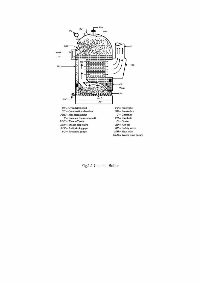
Fig.1.1 Cochran Boiler
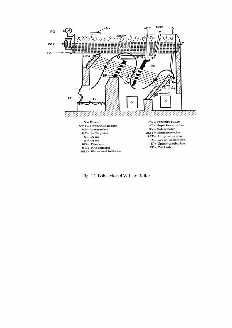
Fig. 1.2 Babcock and Wilcox Boiler
EXPERIMENT NO. 2
Aim: To study the construction and working of various boiler mountings and accessories.
Theory: A boiler is defined as a closed vessel in which steam is produced from water by
combustion of fuel. Also defined as “A combination of apparatus for producing, furnishing,
or recovering heat together with the apparatus for transporting the heat so made available to
the fluid being heated and vaporized.”
Classification of Boilers : The boilers may be classified according to following criteria:
1. According to relative position of water and hot gases.
(a) Water tube boiler: A boiler in which the water flows through the tubes which are
surrounded by hot combustion gases i.e. Babcock and Wilcox, Stirling, Benson boilers etc.
(b) Fire tube boiler: The hot combustion gases pass through the boiler tubes, which
are surrounded by water i.e. Lancashire, Cochran, Locomotive boilers etc.
2. According to water circulation arrangement
(a) Natural circulation: Water circulates in the boiler due to density difference of hot
and cold water e.g., Babcock and Wilcox boiler, Lancashire boiler, Locomotive
boiler etc.
(b) Forced circulation: A water pump forces the water along its path, therefore, the
steam generation rate increases e.g.. Benson, La Mont, Velox boilers etc.
3. According to position of furnaces:
(a) Internally fired: The furnace is located inside the shell e.g., Cochran, Lancashire
boilers etc.
(b) Externally fired: The furnace is located outside the boiler shell i.e. Babcock and
Wilcox, Stirling boilers etc.
4. According to the use: Stationary, Portable, Locomotive or marine boiler.
5. According to position of the boilers: horizontal, inclined or vertical boilers.
Boiler Mountings: The boiler mountings are the part of the boiler and are required for proper functioning. In accordance with the Indian Boiler regulations, of the boiler mountings is essential fitting for
safe working of a boiler. Some of the important mountings are:

Water level Indicator Water level indicator is located in front of boiler in such a position that the level of water can easily be seen by attendant. Two water level indicators are used on all boilers.
Pressure Gauge A pressure gauge is fitted in front of boiler in such a position that the operator can
conveniently read it. It reads the pressure of steam in the boiler and is connected to steam space by a siphon tube.
The most commonly, the Bourdon pressure gauge is used.
Safety Valve Safety valves are located on the top of the boiler. They guard the boiler against the excessive
high pressure of steam inside the drum. If the pressure of steam in the boiler drum exceeds
the working pressure then the safety valve allows blow-off the excess quantity of steam to
atmosphere. Thus the pressure of steam in the drum falls. The escape of steam makes a audio
noise to warm the boiler attendant.
There are four types of safety valve.
1. Dead weight safety valve. 2. Spring loaded safety valve
3. Lever loaded safety valve
4. High steam and low water safety valve.
Fusible Plug It is very important safety device, which protects the fire tube boiler against overheating. It is
located just above the furnace in the boiler. It consists of gun metal plug fixed in a gun metal body with fusible molten metal.
During the normal boiler operation, the fusible plug is covered by water and its temperature
does not rise to its melting state. But when the water level falls too low in the boiler, it
uncovers the fusible plug. The furnace gases heat up the plug and fusible metal of plug melts,
the inner plug falls down The water and steam then rush through the hole and extinguish the
fire before any major damage occurs to the boiler due to overheating.
Blow-Off Cock The function of blow-off cock is to discharge mud and other sediments deposited in the bottom most part of the water space in the boiler, while boiler is in operation. It can also be
used to drain-off boiler water. Hence it is mounted at the lowest part of the boiler. When it is open, water under the pressure rushes out, thus carrying sediments and mud.
Feed Check Valve The feed check valve is fitted to the boiler, slightly below the working level in the boiler. It is used to supply high pressure feed water to boiler. It also prevents the returning of feed water
from the boiler if feed pump fails to work.
Steam Stop Valve The steam stop valve is located on the highest part of the steam space. It regulates the steam supply to use. The steam stop valve can be operated manually or automatically.
Boiler Accessories The accessories are mounted on the boiler to increase its efficiency. These units are optional
on an efficient boiler. With addition of accessories on the boiler, the plant efficiency also
increases. The following accessories are normally used on a modern boiler:
(i) Economizer (ii) Super heater (iii) Air pre heater (iv) Feed water pump (v) Steam injector.
Economizer An economizer is a heat exchanger, used for heating the feed water before it enters the boiler.
The economizer recovers some of waste heat of hot flue gases going to chimney. It helps in improving the boiler efficiency. It is placed in the path of flue gases at the rear end of the
boiler just before air pre-heater.
Super heater It is a heat exchanger in which heat of combustion products is used to dry the wet steam,
pressure remains constant, its volume and temperature increase. Basically, a super heater consists of a set of small diameter U tubes in which steam flows and takes up the heat from
hot flue gases.
Air Pre-heater The function of an air pre-heater is similar to that of an economizer. It recovers some portion
of the waste heat of hot flue gases going to chimney, and transfers same to the fresh air before it enters the combustion chamber.
Due to preheating of air, the furnace temperature increases. It results in rapid combustion of
fuel with less soot, smoke and ash. The high furnace temperature can permit low grade fuel with less atmospheric pollution. The air pre-heater is placed between economizer and
chimney.
Feed Water Pump It is used to feed the water at a high pressure against the high pressure of steam already existing inside the boiler.
Steam Injector A steam injector lifts and forces the feed water into the boiler. It is usually used for vertical
and locomotive boilers and can be accommodated in small space. It is less costly. It does not have any moving parts thus operation is salient.

Fig. 2.1 Water Level Indicator
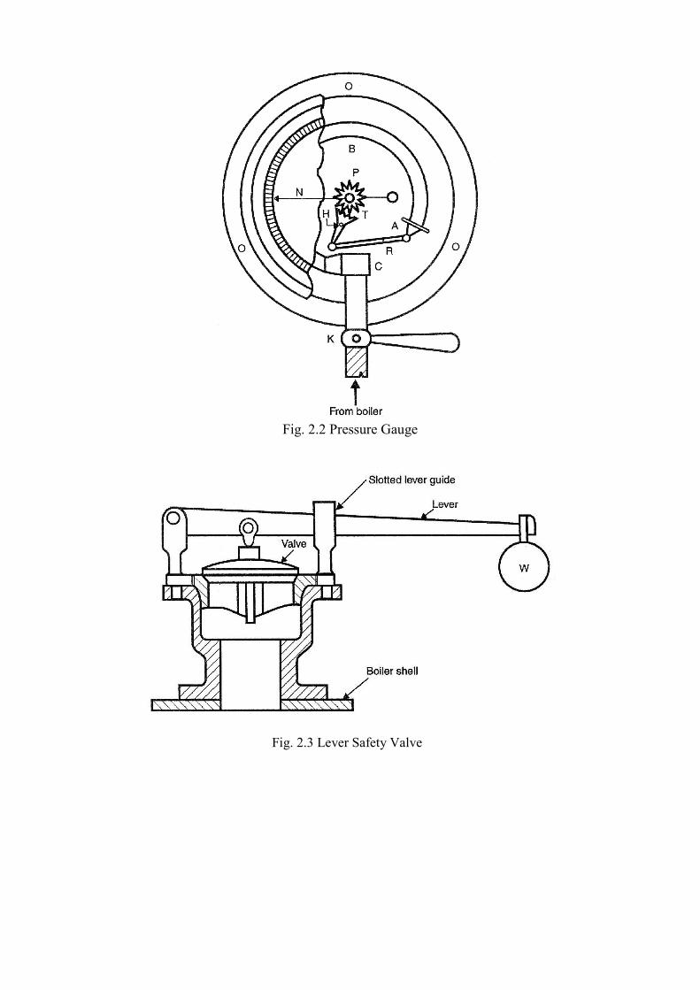
Fig. 2.2 Pressure Gauge Fig. 2.3 Lever Safety Valve
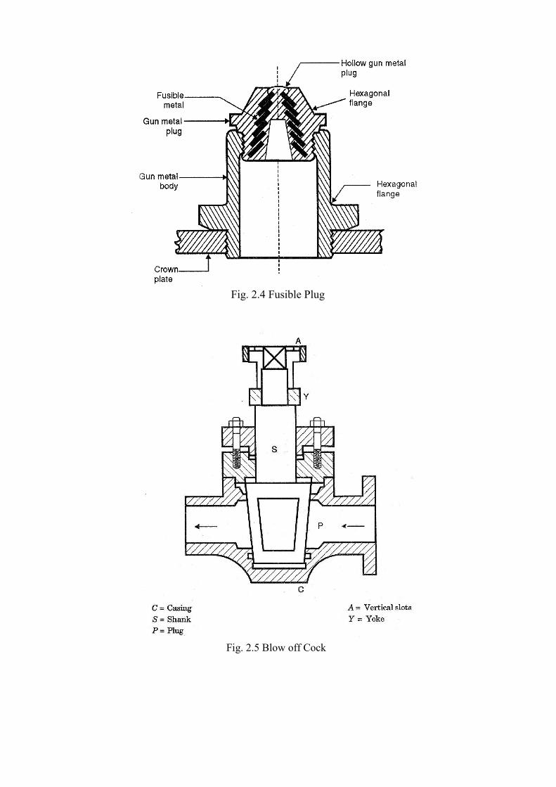
Fig. 2.4 Fusible Plug Fig. 2.5 Blow off Cock

Fig. 2.6 Feed Check Valve
Fig. 2.7 Steam Stop Valve

Fig. 2.8 Economizer
Fig. 2.9 Super Heater
EXPERIMENT NO. 3
Aim: To study the construction and working of 4- stroke diesel engine.
Theory: A machine or device which derives heat from the combustion of fuel and converts
part of this energy into mechanical work is called a heat engine. Heat engines are broadly
classified into internal combustion engines [I.C. engines] and external combustion engines. Petrol and diesel engines fall under the category of internal combustion engines as
these are reciprocating heat engines in which fuel mixed with correct amount of air is burnt
inside a cylinder. The gaseous products of combustion form the working substance which
make the piston move and produce mechanical work at the engine crankshaft. In contrast, the
combustion of fuel in external combustion engines (ex. Steam engines) is external.
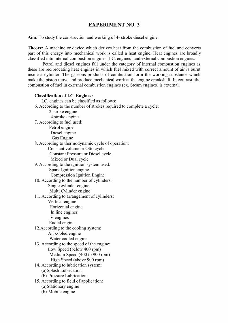
Classification of I.C. Engines: I.C. engines can be classified as follows:
6. According to the number of strokes required to complete a cycle:
2 stroke engine
4 stroke engine
7. According to fuel used: Petrol engine Diesel engine
Gas Engine 8. According to thermodynamic cycle of operation:
Constant volume or Otto cycle
Constant Pressure or Diesel cycle Mixed or Dual cycle
9. According to the ignition system used:
Spark Ignition engine Compression Ignition Engine
10. According to the number of cylinders:
Single cylinder engine Multi Cylinder engine
11. According to arrangement of cylinders:
Vertical engine Horizontal engine
In line engines
V engines Radial engine
12.According to the cooling system:
Air cooled engine Water cooled engine
13. According to the speed of the engine:
Low Speed (below 400 rpm) Medium Speed (400 to 900 rpm)
High Speed (above 900 rpm)
14. According to lubrication system: (a) Splash Lubrication
(b) Pressure Lubrication 15. According to field of application:
(a) Stationary engine
(b) Mobile engine.

Four Stroke Diesel Engine: The cycle of operation in a four stroke diesel engine is completed in two revolutions of
crankshaft or four strokes of piston using diesel oil as fuel. This engine works on diesel cycle. 1. Suction Stroke: Starting of engine is done by an electric motor or manually. In both cases
the energy is supplied to the engine. In this stroke the inlet valve opens and the outlet
valve remains closed. Piston moves from T.D.C. to B.D.C. and in this way a vacuum is
created in the cylinder. This vacuum is filled by air alone and piston reaches to B.D.C. 2. Compression Stroke: Both valves are closed. This time piston moves from B.D.C. to
T.D.C. Air is compressed in this stroke up to a compression ratio of 15:1 to 22:1 and a
very high temperature is produced due to high pressure. The high temperature is the only cause of combustion of the fuel. The piston takes the power in this stroke from
the flywheel. During this stroke the pressure and temperature attain a high value of 40 to 60 bar and 600º C to 700º C.
3. Working Stroke: At the end of compression stroke or when the piston reaches the
T.D.C. position, a fine spray of diesel is injected in the cylinder through injector. The
fuel burns by the heat of compressed air and due to its burning the power is produced.
This power pushes the piston downward i.e. from T.D.C. to B.D.C. The excess energy
of the piston is stored in the flywheel of the engine, which is further used for the
remaining three strokes of the engine. The reciprocating motion of the piston is
converted into the rotary motion of the crankshaft by connecting rod and crank.
During expansion the pressure drops due to increase in volume of gases and
absorption of heat by cylinder walls. 4. Exhaust Stroke: The exhaust valve begins to open when about 85% of the working
stroke is completed. The force of piston coming from B.D.C. to T.D.C. forces the
burnt gases into the exhaust manifold. Some of the gases are forced out due to higher
pressure in the cylinder and the remaining gases are forced out by the piston. Some of
the burnt gases are however left inside the clearance space. The exhaust valve closes
shortly after T.D.C. The inlet valve opens slightly before the end of exhaust and in
this way the cycle repeats.
Comparison between petrol and diesel engine:
S. No. Criteria of comparison Petrol Engine Diesel Engine
1. Working cycle Otto Cycle Diesel cycle
2. Fuel used Petrol Diesel
3. Compression Ratio 5:1 to 9:1 14:1 to 22:1
4. Fuel Supply Carburetor is there Fuel injector is there
5. Ignition Spark plug is required Heat of compressed air
6. Pressure & temperature Lesser due to lower CR Higher due to more compression ratio
7. Weight & size Lighter & Smaller Heavier & Larger
8. Initial cost Lesser More expensive
9. Running cost More Less
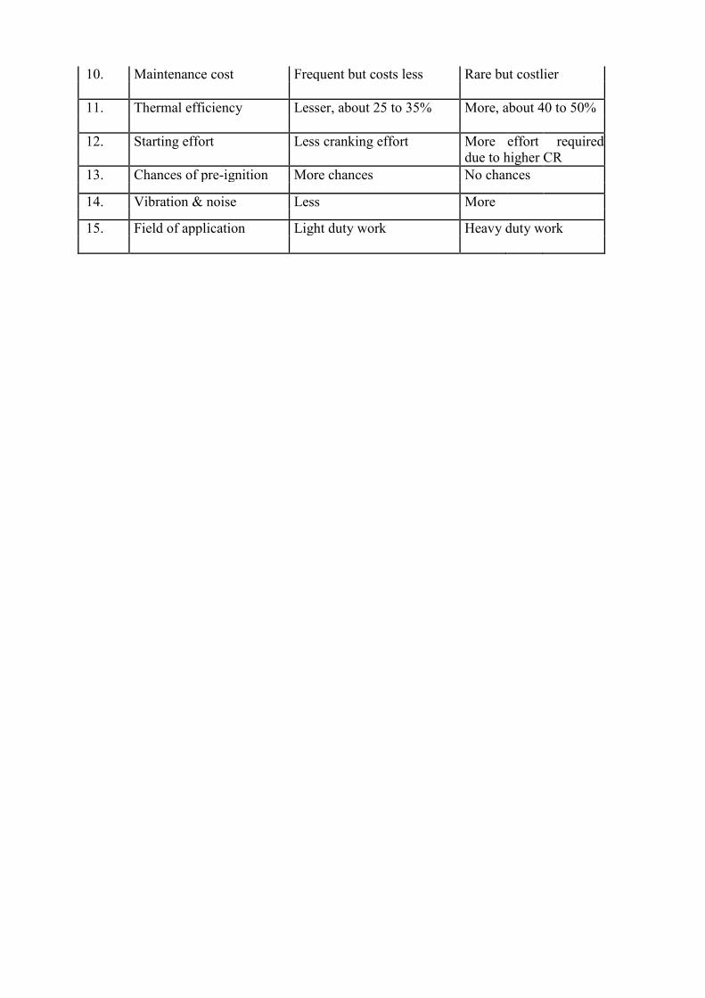
10. Maintenance cost Frequent but costs less Rare but costlier
11. Thermal efficiency Lesser, about 25 to 35% More, about 40 to 50%
12. Starting effort Less cranking effort More effort required due to higher CR
13. Chances of pre-ignition More chances No chances
14. Vibration & noise Less More
15. Field of application Light duty work Heavy duty work
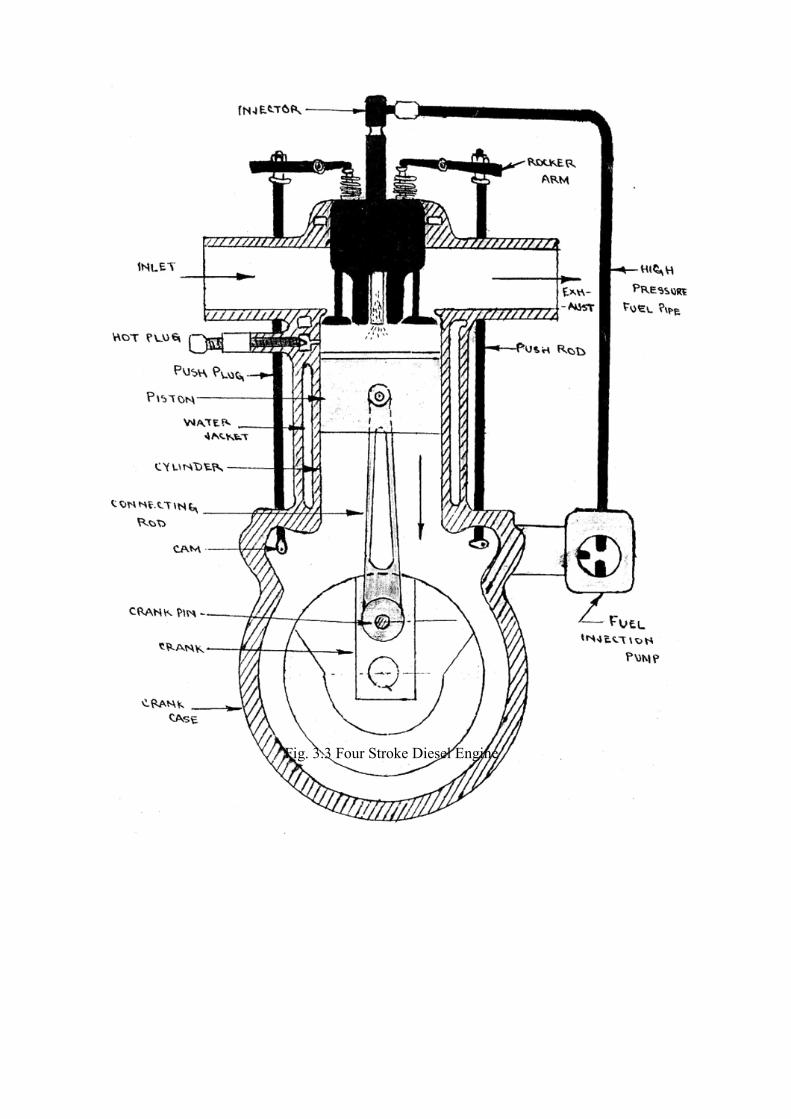
Fig. 3.3 Four Stroke Diesel Engine
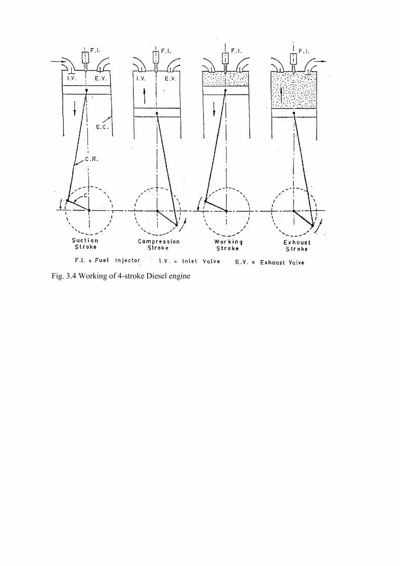
Fig. 3.4 Working of 4-stroke Diesel engine

EXPERIMENT No.-4 AIM:- To study the two stroke & four stroke petrol engine.
APPARATUS USED:- Model of two stroke & four stroke petrol engine.
THEORY/INTRODUCTION:- Any type of engine or m/c which drives heat energy from
the combustion of fuel or any other source and converts this energy into mechanical work is
termed as a heat engine.
Heat engines may be classified into two main classes as follows:-
1. Internal combustion engine
2. External combustion engine
MAIN PARTS OF THE PETROL ENGINE:
1. CYLINDER & CYLINDER HEAD
2. PISTON
3. PISTON RINGS
4. GUDGEON PIN
5. CONNECTING ROD
6. CRANK SHAFT
7. CRANK
8. ENGINE BEARING
9. CRANK CASE
10. FLY WHEEL
11. GOVERNOR
12. VALVES
13. SPARK PLUG
14. CARBURATOR
15. CAM & CAM SHAFT
WORKING PROCESS OF OTTO FOUR STROKE ENGINES
Four Stroke Petrol Engine: The cycle of operation in a four stroke petrol engine is completed in two revolutions of crank
shaft or four strokes of piston. Stroke is defined as the distance traveled by the piston from one of the dead centers to the other dead centre. It is also equal to two times the crank radius.
Hence in a four stroke engine work is obtained only during one stroke out of the four strokes of the piston required to complete one cycle. This engine works on Otto or constant volume
cycle. 1. Suction stroke: To start with the piston is at or very near T.D.C. and the inlet valve is
open and exhaust valve is closed. As the piston moves from T.D.C. to B.D.C. rarefaction is formed in the cylinder which causes the charge to rush in and fill the space vacated by the
piston. The charge consists of a mixture of air and petrol prepared by the carburetor. The admission of charge inside the engine cylinder continues until the inlet valve closes at B.D.C. 2. Compression stroke: Both the valves are closed and the piston moves from B.D.C. to T.D.C. The charge is compressed up to a compression ratio of 5:1 to 9:1 and pressure and temperature at the end of compression are about 6 to 12 bar and 250º C to 300º C respectively. 3. Working, Power or Expansion stroke: When the piston reaches T.D.C. position, or just at
the end of compression stroke, the charge is ignited by causing an electric spark between the electrodes of a spark plug, which is located some where in the walls of cylinder head. During
combustion the chemical energy of fuel is released and there is rise in temperature and pressure of gases. The temperature of gases increases to about 1800º C to 2000º C and the
pressure reaches 30 to 40 bar. Up till now the volume of gases formed however remains almost constant with both valves closed. Now the combustion products expand and push the
piston down the cylinder. The reciprocating piston motion is converted into rotary motion of
crankshaft by a connecting rod and crank. During expansion the pressure drops due to increase in the volume of gases and absorption of heat by cylinder walls. 4. Exhaust stroke: Theoretically exhaust valve opens at the end of working stroke when the piston is at B.D.C. position. But actually exhaust valve begins to open when about 85 % of
the working stroke is completed. A pressure of 4 to 5 bar at this instant forces about 60 % of the burnt gases into the exhaust manifold at high speed. The remaining burnt gases are
cleared off the swept volume when the piston moves from B.D.C. to T.D.C. During this stroke the pressure in side the cylinder is slightly above the atmospheric value. Some of the
burnt gases are however left in the clearance space. The exhaust valve closes shortly after the
piston reaches T.D.C. The inlet valve opens slightly before the end of exhaust stroke and the cycle repeats.
WORKING PROCESS OF TWO STROKE PETROL ENGINE:
In two stroke engine, the working cycle is completed into two stroke of the piston or
one revolution of crankshaft. In two stroke engine the intake and compression processes are
completed during the inward stroke and Expansion & exhaust process during the outward
stroke.
In figure shows a two stroke petrol engine the cylinder L is connected to a closed
crank chamber . during the upward stroke of the piston M, the gases in L are compressed and
at the same time fresh air and fuel (petrol) mixture enters the crank chamber through the
valve V. when the piston moves down wards, V closes and the mixture in the crank chamber
is compressed (in fig.)
1. The piston is moving upwards & is compressing an explosive charge which has
previously been supplied to L. Ignition takes place at the end of the stroke. The
piston then travels downwards due to expansion of the gases.
2. And near the end of this stroke the piston uncovers the exhaust port (E.P) and the
burnt exhaust gases escape through this port.
3. The transfer port (T.P) then is uncovered immediately and the compressed charge
from the crank chamber flows into the cylinder and is deflected upwards by the
hump provided on the head of the piston. It may be noted that the incoming air petrol
mixture helps the removal of gases from the engine cylinder, if in case these exhaust
gases do not leave the cylinder the fresh charge gets diluted and efficiency of the
engine will decreases. The piston then again starts moving from B.D.C to T.D.C and
the charge gets compressed when E.P and T.P are covered by the piston, thus the
cycle is repeated.
APPLICATIONS:-
(i) I.C. engine are used in all road vehicles i.e. automobiles trucks, tractors etc.
(ii) I.C. engine are widely used in rail road, aviation & marine.
(iii) I.C. engine are extensively used in lawn movers boats, concretes mining
equipments etc.
(iv) Petrol engine are used in light motor vehicles.

Fig. 3.1. 4-stroke Petrol engine
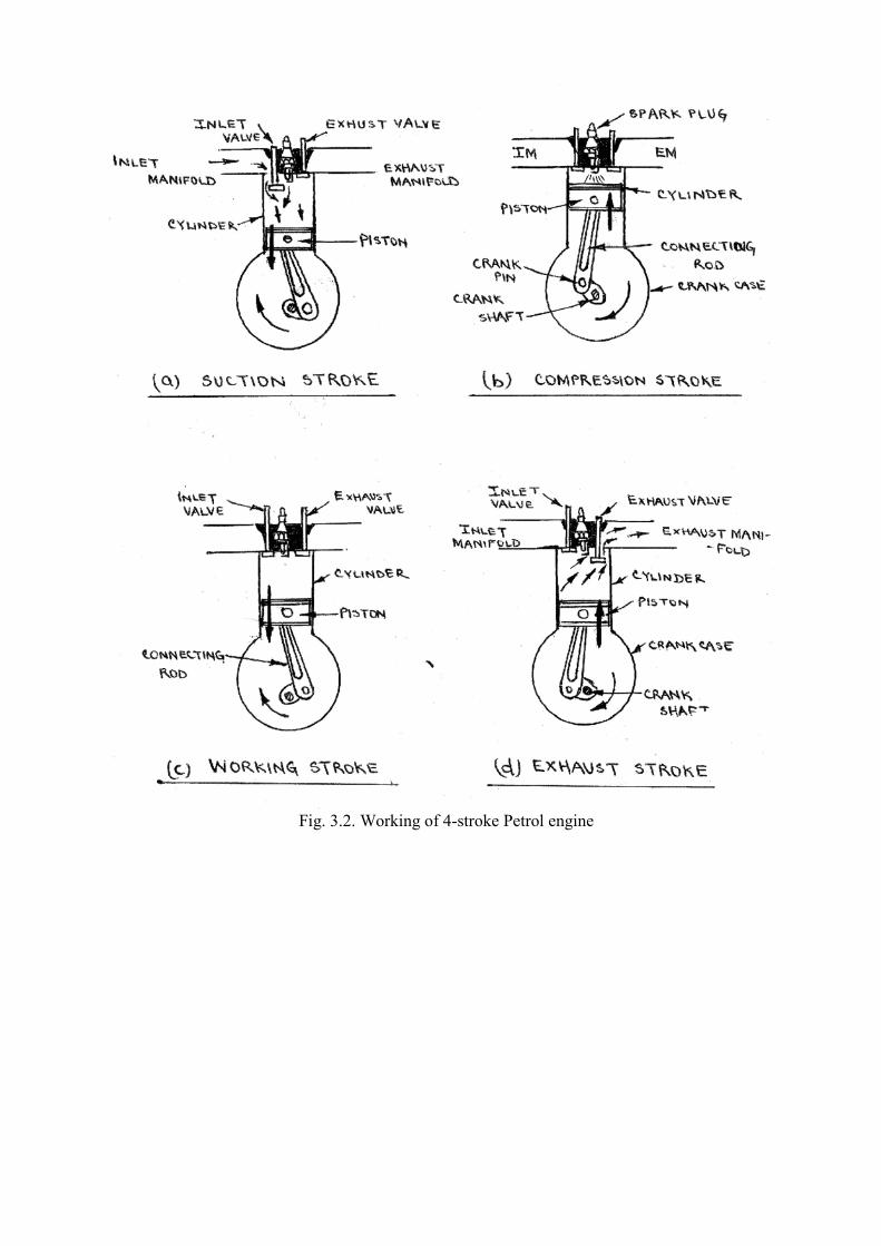
Fig. 3.2. Working of 4-stroke Petrol engine

EXPERIMENT NO. 5 Aim : To calculate the Mechanical Advantage, Velocity Ratio, and efficiency of Single start,
Double start and Triple start Worm & Worm Wheel.
Apparatus Required: Worm & worm wheel mounted on the wall, weights, weight hanger,
pan, ropes, thread, weight box, metre scale & vernier caliper.
Description:
Figure shows the arrangement of Worm and Worm Wheel. It consists of a square threaded
screw called Worm and a toothed wheel called Worm Wheel. The screw is in mesh with the
worm wheel and their axis are at right angles to each other. On the axis of worm is effort
wheel of large diameter, over which a rope passes. The effort (p) is applied at the end of this
rope. On the axis of the worm wheel, a small pulley or a load drum is provided over which a
rope passes at the end of which load to be lifted is attached. The worm and worm wheel
arrangements may be of the following types:
16. SINGLE START: If the worm is single threaded, then for each round of effort
wheel, the worm will push the worm wheel through one tooth. 17. DOUBLE START: For double threaded worm, the worm will push the worm wheel
through two teeth in each revolution of the effort wheel. 18. TRIPLE START: If the worm is triple threaded, then for each revolution of effort
wheel, the worm will push the worm wheel through three teeth.
Case 1:
SINGLE START WORM & WORM WHEEL
For each revolution of effort wheel by applying P effort,
(i) Distance moved by effort P = 2πl = πD
(ii) Load drums turns through = 1/T revolution
(iii) Distance moved by load W = πd / T
Velocity Ratio (V.R.) = Distance moved by effort P/ Distance moved by load
W = πD / πd /T = DT/d Mechanical Advantage (M.A.) = Load lifted / effort applied = W/P
Efficiency (η) = M.A./ V.R.
Case 2:
DOUBLE START WORM & WORM WHEEL
Distance moved by load W= 2 πd/T
Velocity ratio (V.R.) = πD/2πd/T = DT/2d
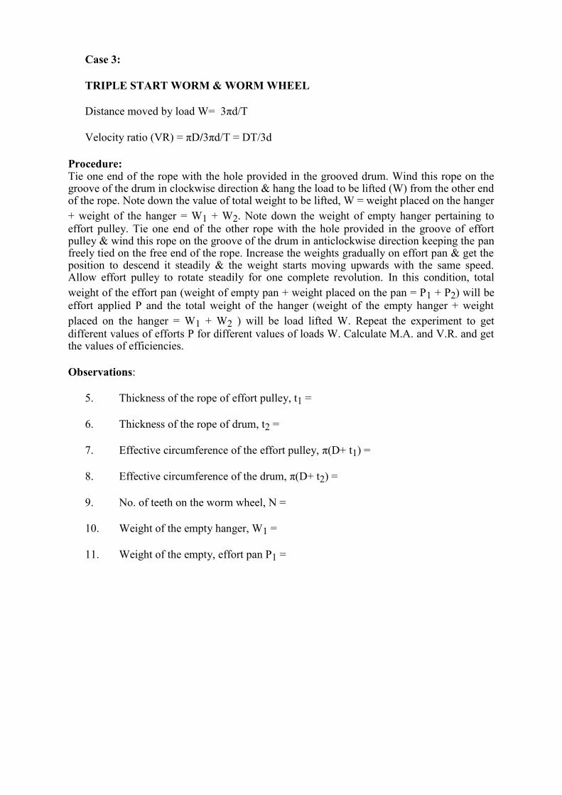
Case 3:
TRIPLE START WORM & WORM WHEEL
Distance moved by load W= 3πd/T
Velocity ratio (VR) = πD/3πd/T = DT/3d
Procedure: Tie one end of the rope with the hole provided in the grooved drum. Wind this rope on the groove of the drum in clockwise direction & hang the load to be lifted (W) from the other end of the rope. Note down the value of total weight to be lifted, W = weight placed on the hanger
+ weight of the hanger = W1 + W2. Note down the weight of empty hanger pertaining to
effort pulley. Tie one end of the other rope with the hole provided in the groove of effort pulley & wind this rope on the groove of the drum in anticlockwise direction keeping the pan freely tied on the free end of the rope. Increase the weights gradually on effort pan & get the position to descend it steadily & the weight starts moving upwards with the same speed. Allow effort pulley to rotate steadily for one complete revolution. In this condition, total
weight of the effort pan (weight of empty pan + weight placed on the pan = P1 + P2) will be
effort applied P and the total weight of the hanger (weight of the empty hanger + weight
placed on the hanger = W1 + W2 ) will be load lifted W. Repeat the experiment to get
different values of efforts P for different values of loads W. Calculate M.A. and V.R. and get the values of efficiencies.
Observations:
5. Thickness of the rope of effort pulley, t1 =
6. Thickness of the rope of drum, t2 =
7. Effective circumference of the effort pulley, π(D+ t1) =
8. Effective circumference of the drum, π(D+ t2) =
9. No. of teeth on the worm wheel, N =
10. Weight of the empty hanger, W1 =
11. Weight of the empty, effort pan P1 =
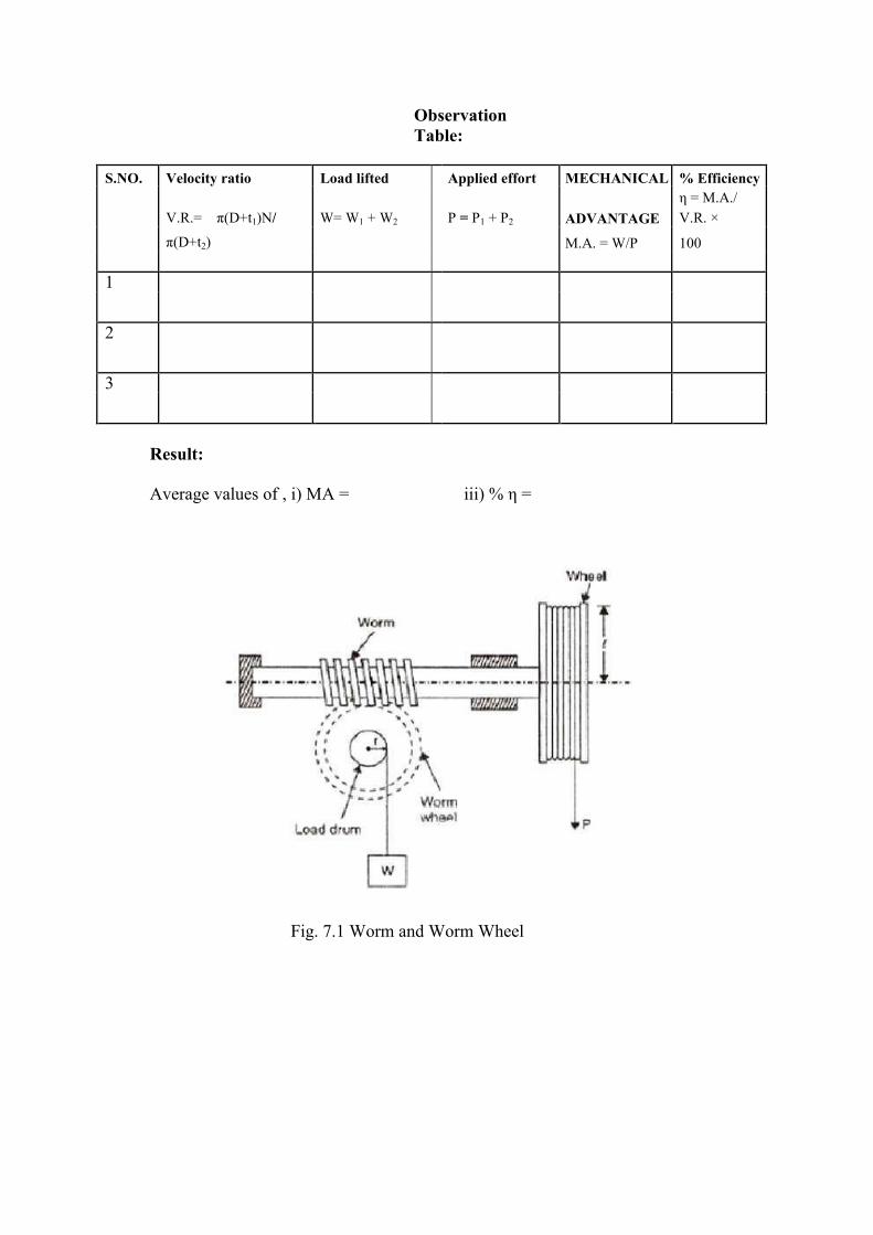
Observation
Table:
S.NO. Velocity ratio Load lifted Applied effort MECHANICAL % Efficiency
V.R.= π(D+t1)N/ W= W1 + W2 P = P1 + P2 ADVANTAGE
η = M.A./
V.R. ×
π(D+t2) M.A. = W/P 100
1
2
3
Result:
Average values of , i) MA = iii) % η =
Fig. 7.1 Worm and Worm Wheel

EXPERIMENT NO. 6
Aim: To calculate the Mechanical Advantage, Velocity Ratio and efficiency
of Single and Double Purchase Winch Crabs
Appratus Required: Single and Double purchase winch crab apparatus, weights, hangers, rope etc.
Theory Winch crabs are the lifting machines in which velocity ratio is increased by a gear system. If only one set of gears is used, the winch crab is called a Single Purchase Winch Crab, and if
two sets are used, it is called Double Purchase Winch Crab.
(i) Single Purchase Winch Crab It consists of a load drum of radius r connected to an axle by gears. The toothed wheel on load drum is called Spur wheel and the small toothed wheel on axle is called Pinion. The axle
is provided with an effort pulley of diameter D.
Let, number of teeth on spur wheel and pinion be T1 and T2 respectively. The effort P be applied at the effort pulley. When one revolution is made by the pulley, the distance moved by the effort = 2πR
= πD
When the axle makes one revolution, due to gear arrangement the load drum also moves T2
number of teeth, which means it makes T2 / T1 revolutions.
The distance over which the load moves = 2π r ( T2 / T1)
Velocity Ratio = distance moved by effort / distance moved by the load
19. 2πR / 2π r ( T2 / T1)
20. D / d ( T1 / T2)
Mechanical Advantage (M.A.) = W / P
Efficiency , η = M.A. / V.R.
(ii) Double Purchase Winch Crab Velocity Ratio of a Winch Crab can be increased by providing another axle with a pair of pinion and gear. Since two pairs of pinion and gear are used it is called Double purchase
winch crab. It is used for lifting heavier loads.
Let, the number of teeth on the two spur wheels be T1 and T3
and number of teeth on the two pinions be T2 and T4 respectively. The effort P be applied at the effort pulley. When one revolution is made by the pulley, the distance moved by the effort = 2πR
= πD
When axle A makes one revolution, axle B is moved by T2 teeth i.e., it makes T2 / T1
revolutions and,
The load axle moves by ( T2 / T1) / ( T4 / T3) revolutions.
Therefore, the distance moved by the load = 2π r ( T2 / T1) / ( T4 / T3)

Velocity Ratio = distance moved by effort / distance moved by the load
(iv) 2πR / 2π r ( T2 / T1) / ( T4 / T3)
(v) D / d [( T1 / T2) ( T3 / T4)]
Mechanical Advantage (M.A.) = W / P
Efficiency , η = M.A. / V.R.
Procedure Measure the circumference of the effort wheel and load axle with the help of thread and scale.
Count the number of teeth on pinion and gear wheel. Hang the load W to the thread passing
round the load axle. Now place sufficient weights in the effort pan till the load W just starts
moving upwards. Note down the weights added in the pan with weight of the pan. Repeat the
procedure for different weights.
Observations
12. No of teeth on pinion-P1 = T2
13. No of teeth on pinion-P2 = T4
14. No of teeth on spur gear S1 =T1
4) No of teeth on spur gearS2 = T3 3. Diameter of the effort pulley =2R 4. Diameter of the load axle = 2r
S.NO. LOAD PLACED EFFORT M.A. V.R. η = Average η Remarks
(W) APPLIED =W/P M.A./V.R.
(P)
Result
Efficiency of the machine, η =
M.A. = V.R. =
Precautions 5. Bearing of axles, the pinion and gear wheel should be properly lubricated so as to
reduce friction. 6. The weights should be put gently in the pan.
7. Weight W should be lifted gradually upwards at uniform speed. 8. To get effective values of circumference the thickness of the ropes should be
measured. 9. Weights of empty hanger and effort pan should always be determined. 10. Load W and effort P should hang freely without touching wall etc. 11. The wound of the rope on the circumferences of the effort pulley should be single i.e.
rope should not overlap.
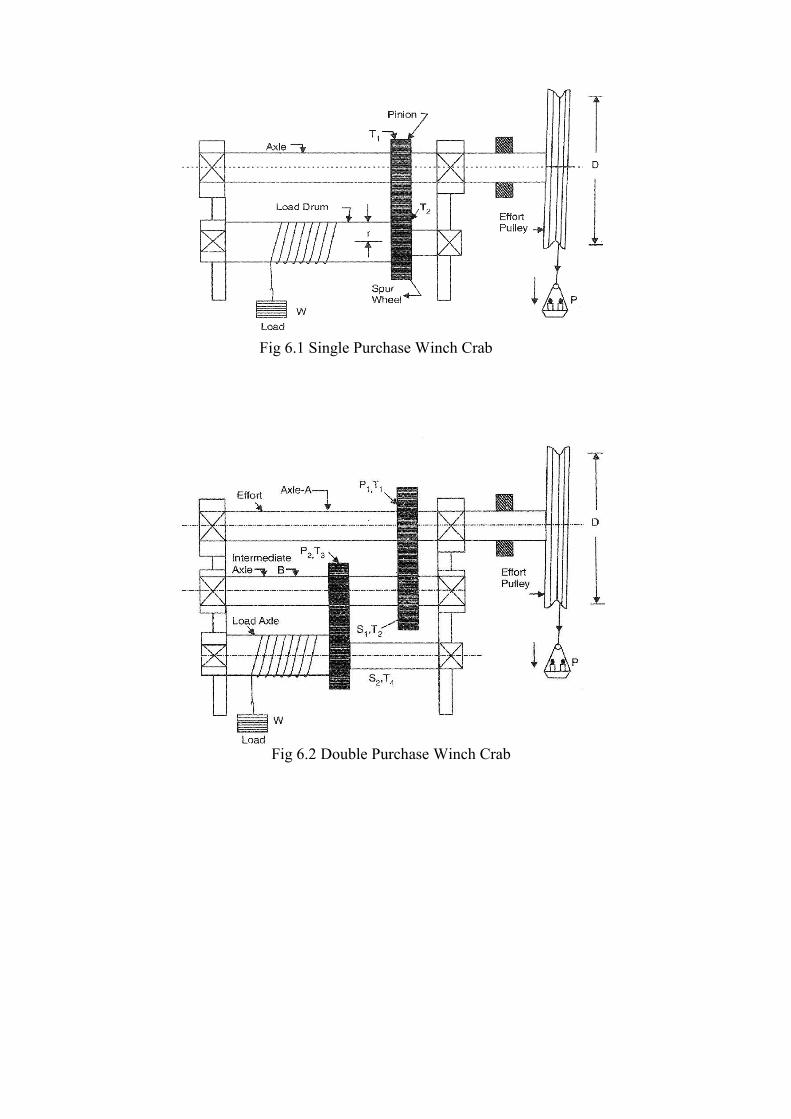
Fig 6.1 Single Purchase Winch Crab Fig 6.2 Double Purchase Winch Crab
EXPERIMENT NO.:- 8
AIM :- To draw shear force and bending moment diagram for a simply supported
beam under point and distributed loads.
APPARATUS USED :- Apparatus of simply supported beam.
THEORY :-
BEAM :- It is a structural member on which the load act perpendicular to axis. It is that
whenever a horizontal beam is loaded with vertical loads, sometimes it bends due to the
action of the loads. The amounts by which a beam bends, depends upon the amount and types
of loads, length of beam, elasticity of the beam and the type of beam. In general beams are
classified as under :
1. Cantilever beam :- It is a beam whose one end is fixed to a rigid support and the
other end is free to move.
2. Simply supported beam :- A beam supported or resting freely on the walls or
columns at its both ends is known as simply supported beam.
3. Rigidly fixed or built-in beam :- A beam whose both the ends are rigidly fixed or
built in walls is called a fixed beam.
4. Continuous beam :- A beam support on more than two supports is known as a
continuous beam. It may be noted that a continuous beam may not be overhanging
beam.
TYPES OF LOADING :
1. Concentrated or point load :- A load acting at a point on a beam is known as
concentrated or a point load.
2. Uniformly distributed load :- A load, which is spread over a beam in such a manner
that each unit length is loaded to a same extent.
3. Uniformly varying load :- A load, which is spread over a beam, in such a manner
that its extent varies uniformly on each unit length.
SHEAR FORCE :- The shear force at the cross-section of a beam may be defined as the
unbalanced vertical forces to the right or left of the section.
BENDING MOMENT :- The bending moment at the cross-section of a beam may be
defined as the algebraic sum of the moment of forces, to the section.
IMPORTANT POINTS :-
1. If loading is uniformly distributed load then shear force diagram will be a curve of
first degree and B.M. diagram will be a curve of second degree.
2. If the loading is point load then its corresponding S.F. diagram would be a curve of
zero degree and the B.M. diagram would be a curve of first degree.
3. If the loading is uniformly varying load its S.F. diagram would be curve of second
degree and BMD will be of third degree.
4. Bending moment is maximum where shear force is zero.
5. In case of simply supported beam the first step is to calculate the reactions at the
support, then we proceed in usual manner.
6. In case of cantilever beam there is no need of finding reaction and start from the free
end of the beam.
7. Point of flexural is the where BM changes its sign.
8. B.M. at the support is zero for simply supported beam.
EXPERIMENT NO.:- 9
AIM:- To study the simple and compound screw jack and to find out Mechanical
Advantage, V.R. and Efficiency.
APPARATUS USED:- Simple and compound screw jack
THEORY :-
Screw Jack :- It is a device employed for lifting heavy loads with help of a small effort
applied at its
handle. The loads are usually centrally loaded upon it. Screw jacks of three types :
1. Simple screw jack
2. Compound Screw jack
3. Differential Screw jack
A simple screw jack consists of a nut, a screw square threaded and a handle fitted to the head
of
the screw. The nut also forms the body of the jack. The load to be lifted is placed on the head
of
the screw. Here the axial distance between corresponding points on two consecutive threads is
known as pitch. If ‘p’ be the pitch of the screw and ‘t’ is the thickness of thread, then p = 2t.
V.R. = Distance moved by the effort/Distance moved by the load
= 2πl / p
Now M.A. = W / P
PROCEDURE :-
When we are moving the handle horizontal direction the screw is also moved it attached with
screw and load is lifted by pitch of the screw, in one revolution of the handle.
OBSERVATION :-
For single Screw Jack :
S.No. Load
(W)in Nt.
Effort(P)
in Nt.
Length of
lever
Pitch of
screw
V.R. M.A. Efficiency
COMPOUND SCREW JACK :-
It is a further improved from of differential screw jack, in which the velocity ratio is further
intensified with the help of a geared screw jack, in which the screw is lifted with the help of
worm and worm wheel, instead of effort at the end of a lever. Now consider a worm geared
screw jack.
Let,
l = Radius of the effort wheel
p = pitch of the screw,
P = effort applied to lift the load,
W = Load lifted and
T = No. of teeth on the worm wheel.
We know that distance moved by effort in one revolution of wheel = 2πl
If the worm is single threaded then the worm wheel move through 1/T revolution.
Therefore distance moved by the load = p/T
V.R. = 2πl/ p/T
M.A. = W/P
Efficiency = M.A. / V.R.
For Compound screw jack :
S.No. Load
(W)in Nt.
Effort(P)
in Nt.
Distance
moved by
effort
V.R. M.A. Efficiency
CALCULATION :-
M.A. = W/P
V.R. = Distance moved by effort/Distance moved by load
Efficiency = M.A. / V.R.
PRECAUTIONS :-
1. Rope should not be overlap.
2. Carefully measure pitch of screw.
3. Effort handle move smoothly do not applied suddenly or jerking.
4. Oiling & greasing should be properly.
5. Effort arm measure very carefully.

EXPERIMENT NO:-10 AIM : - To study the various types of dynamometers.
APPARATUS USED : - Models of dynamometer.
THEORY:- The dynamometer is a device used to measure the torque being exerted along a
rotating shaft so as to determine the shaft power.
Dynamometers are generally classified into:
1) Absorption dynamometers (i.e. Prony brakes, hydraulic or fluid friction brakes, fan
brake and eddy current dynamometers)
2) Transmission dynamometers (i.e. Torsion and belt dynamometers, and strain gauge
dynamometer)
3) Driving dynamometers (i.e. Electric cradled dynamometer)
PRONY BRAKE : - The prony and the rope brakes are the two types of mechanical brakes
chiefly employed for power measurement. The prony brake has two common arrangements in
the block type and the band type. Block type is employed to high speed shaft and band type
measures the power of low speed shaft.
BLOCK TYPE PRONY BRAKE DYNAMOMETER :- The block type prony brake
consists of two blocks of wood of which embraces rather less than one half of the pulley rim.
One block carries a lever arm to the end of which a pull can be applied by means of a dead
weight or spring balance. A second arm projects from the block in the opposite direction and
Mcarries a counter weight to balance the brake when unloaded. When operating, friction
between the blocks and the pulley tends to rotate the blocks in the direction of the rotation of
the shaft. This tendency is prevented by adding weights at the extremity of the lever arm so
that it remains horizontal in a position of equilibrium.
Torque, T = W*l in Nm
Power P = 2πN* T/60 in N-m/s
= 2πN * W*l/60* 1000 in kW
Where, W= weights in Newton
l = Effective length of the lever arm in meter and
N = Revolutions of the crankshaft per minute.
BAND TYPE PRONY BRAKE DYNAMOMETER: - The band type prony brake consists
of an adjustable steel band to which are fastened wooden block which are in contact with the
engine brake-drum. The frictional grip between the band the brake drum can be adjusted by
tightening or loosening the clamp. The torque is transmitted to the knife edge through the
torque arm. The knife edge rests on a platform or communicates with a spring balance.
Frictional torque at the drum = F*r
Balancing torque = W*l
Under equilibrium conditions, T = F*r = W*l in Nm.
Power = 2πN* T/60 in N-m/s
= 2πN * W*l/60* 1000 in kW
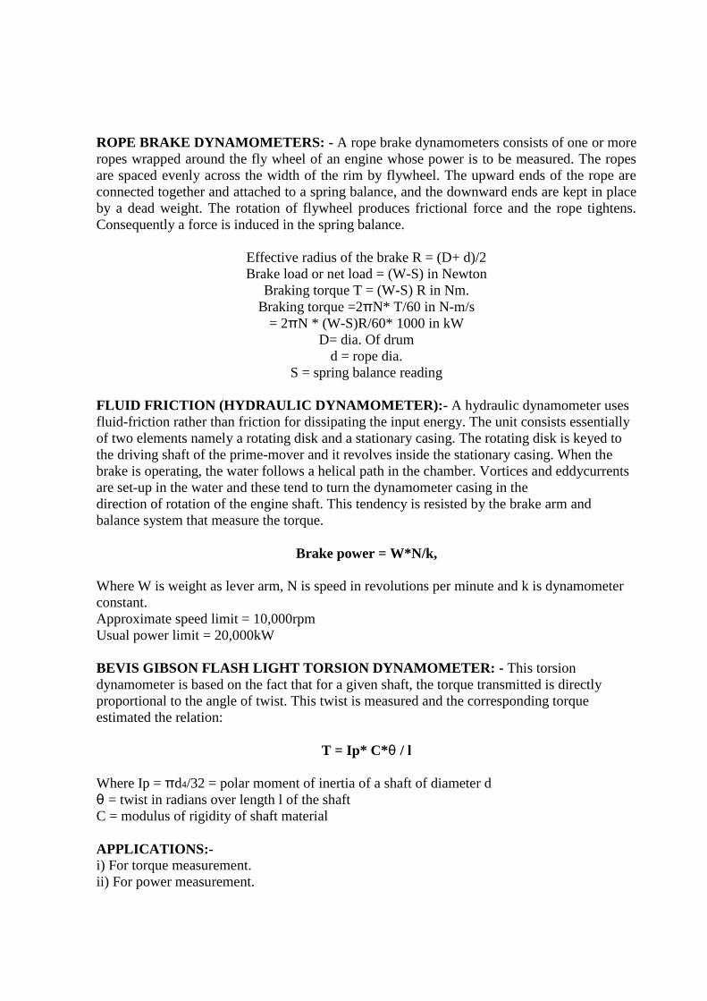
ROPE BRAKE DYNAMOMETERS: - A rope brake dynamometers consists of one or more
ropes wrapped around the fly wheel of an engine whose power is to be measured. The ropes
are spaced evenly across the width of the rim by flywheel. The upward ends of the rope are
connected together and attached to a spring balance, and the downward ends are kept in place
by a dead weight. The rotation of flywheel produces frictional force and the rope tightens.
Consequently a force is induced in the spring balance.
Effective radius of the brake R = (D+ d)/2
Brake load or net load = (W-S) in Newton
Braking torque T = (W-S) R in Nm.
Braking torque =2πN* T/60 in N-m/s
= 2πN * (W-S)R/60* 1000 in kW
D= dia. Of drum
d = rope dia.
S = spring balance reading
FLUID FRICTION (HYDRAULIC DYNAMOMETER):- A hydraulic dynamometer uses
fluid-friction rather than friction for dissipating the input energy. The unit consists essentially
of two elements namely a rotating disk and a stationary casing. The rotating disk is keyed to
the driving shaft of the prime-mover and it revolves inside the stationary casing. When the
brake is operating, the water follows a helical path in the chamber. Vortices and eddycurrents
are set-up in the water and these tend to turn the dynamometer casing in the
direction of rotation of the engine shaft. This tendency is resisted by the brake arm and
balance system that measure the torque.
Brake power = W*N/k,
Where W is weight as lever arm, N is speed in revolutions per minute and k is dynamometer
constant.
Approximate speed limit = 10,000rpm
Usual power limit = 20,000kW
BEVIS GIBSON FLASH LIGHT TORSION DYNAMOMETER: - This torsion
dynamometer is based on the fact that for a given shaft, the torque transmitted is directly
proportional to the angle of twist. This twist is measured and the corresponding torque
estimated the relation:
T = Ip* C*θ / l
Where Ip = πd4/32 = polar moment of inertia of a shaft of diameter d
θ = twist in radians over length l of the shaft
C = modulus of rigidity of shaft material
APPLICATIONS:-
i) For torque measurement.
ii) For power measurement.
EXPERIMENT NO.-11 AIM:- To study the constructional features & working of Pelton, Kaplan and Francis
turbine.
APPARATUS USED:- Models of Pelton turbine, Kaplan turbine and Francis turbine.
THEORY:- A hydraulic turbine uses the potential and kinetic energy of water and converts it
into usable mechanical energy. The fluid energy is available in the nature or artificial high
level water reservoirs which are created by constructing dams at appropriate places in the flow
path of rivers. When water from the reservoir is taken to the turbine, transfer of energy takes
place in the blade passages of the unit.
Mainly two types of turbine:
1) Impulse turbine
2) Reaction turbine
In addition to the concept of impulse and reaction, hydraulic turbines may be further
classified into various kinds according to:
(a) Direction of water flow through runner:
1. Tangential flow (Pelton wheel)
2. Axial or parallel flow (Kaplan turbine)
3. Mixed-radial and axial(Modern Francis turbine)
4. Outward radial flow(Fourneyron turbine)
5. Inward radial flow(old Francis turbine)
(b) Available head and discharge:
1. High head turbines (above 250m)- Pelton wheel
2. Medium head turbine (60m to 250m)- Modern Francis turbine
3. Low head turbine (upto 30m.) – Propeller and Kaplan turbine
(c) Specific speed:
1. For Pelton wheel
(i) Ns = 9-17rpm. for a slow runner
(ii) Ns = 17-25rpm. for a normal runner
(iii) Ns = 25-30 rpm. for fast runner
(iv) Ns = 40 rpm. for a double jet
2. Francis turbine
(i) Ns = 50-100 rpm. for a slow runner
(ii) Ns = 100-150 rpm. for a normal runner
(iii) Ns = 150-250 rpm. for a fast runner
3. Kaplan turbine
(i) Ns = 250-850 rpm.
(c) Disposition of shaft:
1. Horizontal shaft
2. vertical shaft
PELTON TURBINE:- A pelton wheel is a free – jet impulse turbine named after the
American engineer Lesser Pelton (1829-1908) Who contributed much ti its development. It is
simple, robust and the only hydraulic turbine which operates efficiently and is invariably used
for heads in excess of 450m. Smooth running and good performance are other common
features of this unit.
Component Parts:
i) Penstock
ii) Spear and nozzle
iii) Runner with buckets
iv) Casing Governing mechanism
FRANCIS TURBINE:- Francis turbine is an inward flow reaction turbine which was
designed and developed by the American engineer James B. Francis (1815-1892). In the
earlier stages of its development, Francis turbine had a purely radial flow runner; the flow
passing through the runner had velocity component only in a plane normal to the axis of the
runner. The modern Francis turbine is, however, a mixed flow unit in which the water enters
the runner radially at its outer periphery and leaves axially at its centre.
Component Parts:
i) Penstock
ii) Scroll casing
iii) Guide vanes or wicket gates
iv) Guide wheel and governing mechanism
v) Runner and runner blades
vi) Draft tube
KAPLAN TURBINE: The propeller turbine is a reaction turbine which is particularly suited
for low head (upto 30m) and high flow installations.i.e at barrages in rivers. The unit is like
the propeller of a ship operating in reverse. The ship propeller rotates, thrusts the water away
behind it and thus causes the ship to move forward. In a propeller turbine, the water flows
through the propeller and sets it in motion. Water enter the turbine laterally, gets deflected by
the guide vanes and the flows through the propeller. For this reason, these machines are
referred to as axial flow units.
Component Parts:
i) Scroll casing
ii) Stay ring
iii) Guide mechanism
iv) Draft tube
APPLICATIONS:-
i) In thermal power plans.
ii) In hydro-electric power plants.
EXPERIMENT No.-12 AIM :- To prepare stress-strain diagram for mild steel and cast iron specimens under
tension and compression respectively on a U.T.M.
APPARATUS :- A UTM, mild steel specimen, vernier caliper/micrometer, dial gauge &
graph paper.
THEORY :- Various m/c and structure components are subjected to tensile loading in
numerous application. For safe design of these components, there ultimate tensile strength and
ductility one to be determine before actual use. Tensile test can be conducted on UTM. A
material when subjected to a tensile load resists the applied load by developing internal
resisting force. These resistances come due to atomic bonding between atoms of the material.
The resisting force for unit normal cross-section area is known as stress.
The value of stress in material goes on increasing with an increase in applied tensile load, but
it has a certain maximum (finite) limit too. The minimum stress, at which a material fails, is
called ultimate tensile strength. The end of elastic limit is indicated by the yield point (load).
This can be sen during experiment as explained later in procedure with increase in loading
beyond elastic limit original cross-section area (Ao) goes on decreasing and finally reduces to
its minimum value when the specimen breaks.
ABOUT OF UTM & ITS SPECIFICATIONS :-
The tensile test is conducted on UTM. It is hydraulically operates a pump, oil in oil sump,
load dial indicator and central buttons. The left has upper, middle and lower cross heads i.e;
specimen grips (or jaws). Idle cross head can be moved up and down for adjustment. The
pipes connecting the lift and right parts are oil pipes through which the pumped oil under
pressure flows on left parts to more the cross-heads.
SPECIFICATIONS :-
1. Load capacity = 0-40000 kgf.
2. Least count = 8kgf.
3. Overall dimn. =
4. Power supply = 440V
PROCEDURE :-
1. The load pointer is set at zero by adjusting the initial setting knob.
2. The dial gauge is fixed and the specimen for measuring elongation of small amounts.
3. Measuring the diameter of the test piece by vernier caliper at least at three places and
determine the mean value also mark the gauge length.
4. Now the specimen is gripped between upper and middle cross head jaws of the m/c.
5. Set the automatic graph recording system.
6. Start the m/c and take the reading.
7. The specimen is loaded gradually and the elongation is noted until the specimen
breaks.

OBSEVATION :-
(I) Initial diameter of specimen d1 = ------
(II) Initial gauge length of specimen L1 = -----
(III) Initial cross-section area of specimen A1 = ----
(IV) Load of yield point Ft. = -----
(V) Ultimate load after specimen breaking F = -----
(VI) Final length after specimen breaking L2 = ------
(VII) Dia. Of specimen at breaking place d2 = -------
(VIII) Cross section area at breaking place A2 = ----
CALCULATION :-
(i) Ultimate tensile strength = ------
(ii) Percentage elongation % = ------
(iii) Modulus of elasticity E = --------
(iv) Yield stress = --------
(v) % reduction in area = -------
PRECAUTIONS :-
1. The specimen should be prepared in proper dimentions.
2. The specimen should be properly to get between the jaws.
3. Take reading carefully.
4. After breaking specimen stop to m/c.