Lab 11.2.1a Configuring Standard Access Lists
45
237 - 281 CCNA 2: Routers and Routing Basics v 3.1 - Lab 11.2.1a Copyright 2003, Cisco Systems, Inc. Lab 11.2.1a Configuring Standard Access Lists Objective • Configure, and apply a standard ACL to permit or deny specific traffic. • Test the ACL to determine if the desired results were achieved. Background/Preparation Cable a network similar to the one in the diagram. Any router that meets the interface requirements displayed on the above diagram, such as 800, 1600, 1700, 2500, 2600 routers, or a combination, may be used. Please refer to the chart at the end of the lab to correctly identify the interface identifiers to be used based on the equipment in the lab. The configuration output used in this lab is produced from 1721 series routers. Any other router used may produce a slightly different output. The following steps are intended to be executed on each router unless specifically instructed otherwise. Start a HyperTerminal session as performed in the Establishing a HyperTerminal session lab. Note: Go to the erase and reload instructions at the end of this lab. Perform those steps on the router in this lab assignment before continuing.
Transcript of Lab 11.2.1a Configuring Standard Access Lists

237 - 281 CCNA 2: Routers and Routing Basics v 3.1 - Lab 11.2.1a Copyright 2003, Cisco Systems, Inc.
Lab 11.2.1a Configuring Standard Access Lists
Objective • Configure, and apply a standard ACL to permit or deny specific traffic.
• Test the ACL to determine if the desired results were achieved.
Background/Preparation Cable a network similar to the one in the diagram. Any router that meets the interface requirements displayed on the above diagram, such as 800, 1600, 1700, 2500, 2600 routers, or a combination, may be used. Please refer to the chart at the end of the lab to correctly identify the interface identifiers to be used based on the equipment in the lab. The configuration output used in this lab is produced from 1721 series routers. Any other router used may produce a slightly different output. The following steps are intended to be executed on each router unless specifically instructed otherwise.
Start a HyperTerminal session as performed in the Establishing a HyperTerminal session lab.
Note: Go to the erase and reload instructions at the end of this lab. Perform those steps on the router in this lab assignment before continuing.
238 - 281 CCNA 2: Routers and Routing Basics v 3.1 - Lab 11.2.1a Copyright 2003, Cisco Systems, Inc.
Step 1 Configure the hostname and passwords on the Gadsden router a. On the Gadsden router, enter the global configuration mode and configure the hostname as
shown in the chart. Then configure the console, virtual terminal and enable passwords. Configure the FastEthernet interface on the router according to the chart.
Step 2 Configure the hosts on the Ethernet segment a. Host 1
IP address 192.168.14.2 Subnet mask 255.255.255.0 Default gateway 192.168.14.1
b. Host 2
IP address 192.168.14.3 Subnet mask 255.255.255.0 Default gateway 192.168.14.1
Step 3 Save the configuration information from the privileged EXEC command mode
GAD#copy running-config startup-config
Step 4 Confirm connectivity by pinging the default gateway from both hosts a. If the pings are not successful, correct the configuration and repeat until they are successful.
Step 5 Prevent access to the Ethernet interface from the hosts a. Create an access list that will prevent access to FastEthernet 0 from the 192.168.14.0 network.
b. At the router configuration prompt type the following command:
GAD(config)#access-list 1 deny 192.168.14.0 0.0.0.255GAD(config)#access-list 1 permit any
c. Why is the second statement needed? __________________________________________
Step 6 Ping the router from the hosts
a. Were these pings successful? ________________________________________________
b. Why or why not? _________________________________________________________
Step 7 Apply the Access list to the interface a. At the FastEthernet 0 interface mode prompt type the following:
GAD(config-if)#ip access-group 1 in
Step 8 Ping the router from the hosts
a. Were these pings successful? ________________________________________________
b. Why or why not? _________________________________________________________

239 - 281 CCNA 2: Routers and Routing Basics v 3.1 - Lab 11.2.1a Copyright 2003, Cisco Systems, Inc.
Step 9 Create a new access list a. Now create an access list that will not allow the even numbered hosts to ping but permit the odd
numbered hosts to ping.
b. What will that access list look like? Finish this command with an appropriate comparison IP address (aaa.aaa.aaa.aaa) and wildcard mask (www.www.www.www):
access-list 2 permit aaa.aaa.aaa.aaa www.www.www.www
c. Why was it not necessary to have the permit any statement at the end this time?
_______________________________________________________________________
Step 10 Apply access list to the proper router interface a. First remove the old access list application by typing no ip access-group 1 in at the
interface configuration mode.
b. Apply the new access list by typing ip access-group 2 in
Step 11 Ping the router from each hosts
a. Was the ping from host 1 successful? ___________________________________________
b. Why or why not? __________________________________________________________
c. Was the ping from host 2 successful? ___________________________________________
d. Why or why not? __________________________________________________________
Upon completion of the previous steps, logoff by typing exit. Turn the router off.

240 - 281 CCNA 2: Routers and Routing Basics v 3.1 - Lab 11.2.1a Copyright 2003, Cisco Systems, Inc.
Erasing and reloading the router Enter into the privileged EXEC mode by typing enable.
Router>enable
If prompted for a password, enter class. If class does not work, ask the instructor for assistance.
At the privileged EXEC mode, enter the command erase startup-config.
Router#erase startup-config
The responding line prompt will be:
Erasing the nvram filesystem will remove all files! Continue? [confirm]
Press Enter to confirm.
The response should be:
Erase of nvram: complete
Now at the privileged EXEC mode, enter the command reload.
Router#reload
The responding line prompt will be:
System configuration has been modified. Save? [yes/no]:
Type n and then press Enter.
The responding line prompt will be:
Proceed with reload? [confirm]
Press Enter to confirm.
In the first line of the response will be:
Reload requested by console.
After the router has reloaded the line prompt will be:
Would you like to enter the initial configuration dialog? [yes/no]:
Type n and then press Enter.
The responding line prompt will be:
Press RETURN to get started!
Press Enter.
The router is ready for the assigned lab to be performed.

241 - 281 CCNA 2: Routers and Routing Basics v 3.1 - Lab 11.2.1a Copyright 2003, Cisco Systems, Inc.
Router Interface Summary Router Model
Ethernet Interface #1
Ethernet Interface #2
Serial Interface #1
Serial Interface #2
Interface #5
800 (806) Ethernet 0 (E0) Ethernet 1 (E1) 1600 Ethernet 0 (E0) Ethernet 1 (E1) Serial 0 (S0) Serial 1 (S1) 1700 FastEthernet 0 (FA0) FastEthernet 1 (FA1) Serial 0 (S0) Serial 1 (S1) 2500 Ethernet 0 (E0) Ethernet 1 (E1) Serial 0 (S0) Serial 1 (S1) 2600 FastEthernet 0/0
(FA0/0) FastEthernet 0/1 (FA0/1) Serial 0/0 (S0/0) Serial 0/1
(S0/1) In order to find out exactly how the router is configured, look at the interfaces. This will identify the type of router as well as how many interfaces the router has. There is no way to effectively list all of the combinations of configurations for each router class. What is provided are the identifiers for the possible combinations of interfaces in the device. This interface chart does not include any other type of interface even though a specific router may contain one. An example of this might be an ISDN BRI interface. The string in parenthesis is the legal abbreviation that can be used in IOS command to represent the interface.

242 - 281 CCNA 2: Routers and Routing Basics v 3.1 - Lab 11.2.1b Copyright 2003, Cisco Systems, Inc.
Lab 11.2.1b Standard ACLs
Objective Plan, configure, and apply a standard ACL to permit or deny specific traffic and test the ACL to determine if the desired results were achieved.
Scenario The company home office in Gadsden (GAD) provides services to branch offices such as the Birmingham (BHM) office. These offices have some minor security and performance concerns. A Standard ACL needs to be implemented as a simple and effective tool to control traffic

243 - 281 CCNA 2: Routers and Routing Basics v 3.1 - Lab 11.2.1b Copyright 2003, Cisco Systems, Inc.
Infrastructure Host #3 represents the kiosk station that needs to have its access limited to the local network.
Host #4 represents another host in the BHM office and the Loopback 0 interface on the GAD router represents the Internet.
Step 1 Basic Router Interconnection a. Interconnect the routers as shown in the diagram.
Step 2 Basic Configuration a. The router may contain configurations from a previous use. For this reason, erase the startup
configuration and reload the router to remove any residual configurations. Refer to the table on the first page and setup the router and host configurations. Verify reachability by pinging all systems and routers from each system.
b. To simulate the Internet, add the following configuration to the GAD router.
GAD(config)#interface loopback0GAD(config-if)#address 172.16.1.1 255.255.255.0GAD(config-if)#exitGAD(config)#router ripGAD(config-router)#network 172.16.0.0GAD(config-if)#^z
Step 3 Establish Access List Requirements a. The kiosk station (host 3) needs to have its access limited to the local network. It is determined
that a standard access list needs to be created to prevent traffic from this host from reaching any other networks. The access control list should block traffic from this host and not affect other traffic from this network. A standard IP ACL satisfies this requirement as it filters based on the source address to any destination.
What source address of the kiosk? ____________________________
Step 4 Plan the Access List Requirements a. As with any project, the most important part of the process is the planning. First, define the
information needed to create the ACL. Remember that statements are added sequentially to an ACL. Therefore, the order of the statements needs to be planned carefully.
b. It has been determined that this ACL will require 2 logical steps. Each of these steps can be accomplished with one statement each. As a planning tool, a text editor like Notepad can be used to organize the logic and then write the list. In the text editor enter the logic by typing:
! stop traffic from host 3
! permit all other traffic

244 - 281 CCNA 2: Routers and Routing Basics v 3.1 - Lab 11.2.1b Copyright 2003, Cisco Systems, Inc.
c. From this logic the actual ACL will be written. Using the tables below, document the information for each statement.
stop traffic from host 3 List # permit or deny Source address Wildcard mask
permit all other traffic List # permit or deny Source address Wildcard mask
d. What would be the result of not including a statement to permit all other source addresses?
_____________________________________________________________________________________
e. What would be the result of reversing the order of the 2 statements in the list?
_____________________________________________________________________________________
f. Why are both statements using the same ACL number?
_____________________________________________________________________________________
g. The final step in the planning process is to determine the best location for the access list and the direction the list should be applied. Examine the internetwork diagram and choose the appropriate interface and direction. Document this in the table below:
Router Interface Direction
Step 5 Write and Apply the ACL a. Using the previously constructed logic and information of the access list, complete the
commands in the text editor. The list syntax should look similar to:
! stop traffic from host 3
access-list # deny address wildcard
! permit all other traffic
access-list # permit address wildcard
b. Add to this text file the configuration statements to apply the list.
The configuration statements take the form of:
interface type #/#
ip access-group # {in, out}

245 - 281 CCNA 2: Routers and Routing Basics v 3.1 - Lab 11.2.1b Copyright 2003, Cisco Systems, Inc.
c. Now the text file configuration needs to be applied to the router. Enter the configuration mode on the appropriate router and copy and paste the configuration. Observe the CLI display to ensure no errors were encountered.
Step 6 Verify the ACL Now that the ACL is completed, the ACL needs to be confirmed and tested.
a. The first step is to check the list to see if it was configured properly on the router. To check the ACL logic use the show access-lists command. Record the output.
_____________________________________________________________________________________
_____________________________________________________________________________________
_____________________________________________________________________________________
b. Next, verify that the access list was applied to the proper interface and in the correct direction. To do this examine the interface with the show ip interface command. Look at the output from each interface and record the lists applied to the interface.
Interface ________________________________________________________________
Outgoing access list is ____________________________________________________
Inbound access list is ____________________________________________________
c. Finally, test the functionality of the ACL by trying to send packets from the source host and verify that is to be permitted or denied as appropriate. In this case, ping will be used to test this.
[ ] verify that host 3 CAN ping host 4
[ ] verify that host 3 CANNOT ping host 1
[ ] verify that host 3 CANNOT ping host 2
[ ] verify that host 3 CANNOT ping GAD Fa0/0
[ ] verify that host 3 CANNOT ping GAD LO0
[ ] verify that host 4 CAN ping host 1
[ ] verify that host 4 CAN ping host 2
[ ] verify that host 4 CAN ping GAD Fa0/0
[ ] verify that host 4 CAN ping GAD LO0
Step 7 Document the ACL a. As a part of all network management, documentation needs to be created. Using the text file
created for the configuration, add additional comments. This file should also contain output from the show access-lists and the show ip interface commands.
b. The file should be saved with other network documentation. The file naming convention should reflect the function of the file and the date of implementation.
That should complete the ACL project.
c. Once finished, erase the start-up configuration on routers, remove and store the cables and adapter. Also logoff and turn the router off.
246 - 281 CCNA 2: Routers and Routing Basics v 3.1 - Lab 11.2.2a Copyright 2003, Cisco Systems, Inc.
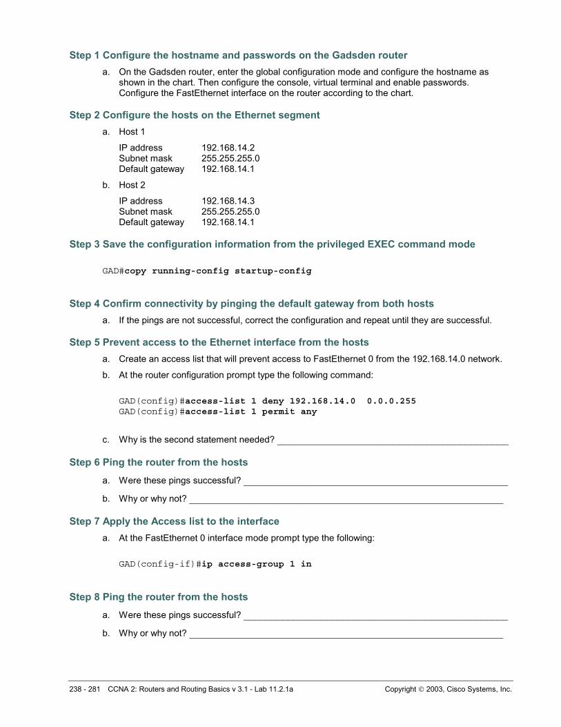
Lab 11.2.2a Configuring Extended Access Lists
Objective • Configure, and apply an extended ACL to permit or deny specific traffic.
• Test the ACL to determine if the desired results were achieved.
Background/Preparation Cable a network similar to the one in the diagram. Any router that meets the interface requirements displayed on the above diagram, such as 800, 1600, 1700, 2500, 2600 routers, or a combination, may be used. Please refer to the chart at the end of the lab to correctly identify the interface identifiers to be used based on the equipment in the lab. The configuration output used in this lab is produced from 1721 series routers. Any other router used may produce a slightly different output. The following steps are intended to be executed on each router unless specifically instructed otherwise.
Start a HyperTerminal session as performed in the Establishing a HyperTerminal session lab.
Note: Go to the erase and reload instructions at the end of this lab. Perform those steps on the router in this lab assignment before continuing.

247 - 281 CCNA 2: Routers and Routing Basics v 3.1 - Lab 11.2.2a Copyright 2003, Cisco Systems, Inc.
Step 1 Configure the hostname and passwords on the GAD router a. On the GAD router, enter the global configuration mode and configure the hostname as shown in
the chart. Then configure the console, virtual terminal and enable passwords. Configure the FastEthernet interface on the router according to the chart.
b. Allow HTTP access by issuing the ip http server command in global configuration mode.
Step 2 Configure the hosts on the Ethernet segment a. Host 1
IP address 192.168.14.2 Subnet mask 255.255.255.0 Default gateway 192.168.14.1
b. Host 2
IP address 192.168.14.3 Subnet mask 255.255.255.0 Default gateway 192.168.14.1
Step 3 Save the configuration information from the privileged EXEC command mode
GAD#copy running-config startup-config
Step 4 Confirm connectivity by pinging the default gateway from both hosts a. If the pings are not successful, correct the configuration and repeat until they are successful.
Step 5 Connect to the router using the Web browser a. From a host, connect to the router using a Web browser to ensure that the Web server function
is active.
Step 6 Prevent access to HTTP (port 80) from the Ethernet interface hosts a. Create an access list that will prevent Web browsing access to FastEthernet 0 from the
192.168.14.0 network.
b. At the router configuration prompt type the following commands:
GAD(config)#access-list 101 deny tcp 192.168.14.0 0.0.0.255 any eq 80 GAD(config)#access-list 101 permit ip any any
c. Why is the second statement needed? __________________________________________
Step 7 Apply the access list to the interface a. At the FastEthernet 0 interface mode prompt type:
GAD(config-if)#ip access-group 101 in
Step 8 Ping the router from the hosts
a. Were these pings successful? ________________________________________________
b. If they were, why? _________________________________________________________
248 - 281 CCNA 2: Routers and Routing Basics v 3.1 - Lab 11.2.2a Copyright 2003, Cisco Systems, Inc.
Step 9 Connect to the router using the web browser
a. Was the browser able to connect? _____________________________________________
Step 10 Telnet to the router from the hosts
a. Were you able to Telnet successfully? __________________________________________
b. Why or why not? __________________________________________________________
Upon completion of the previous steps, logoff by typing exit. Turn the router off.

249 - 281 CCNA 2: Routers and Routing Basics v 3.1 - Lab 11.2.2a Copyright 2003, Cisco Systems, Inc.
Erasing and reloading the router Enter into the privileged EXEC mode by typing enable.
Router>enable
If prompted for a password, enter class. If class does not work, ask the instructor for assistance.
At the privileged EXEC mode, enter the command erase startup-config.
Router#erase startup-config
The responding line prompt will be:
Erasing the nvram filesystem will remove all files! Continue? [confirm]
Press Enter to confirm.
The response should be:
Erase of nvram: complete
Now at the privileged EXEC mode, enter the command reload.
Router#reload
The responding line prompt will be:
System configuration has been modified. Save? [yes/no]:
Type n and then press Enter.
The responding line prompt will be:
Proceed with reload? [confirm]
Press Enter to confirm.
In the first line of the response will be:
Reload requested by console.
After the router has reloaded the line prompt will be:
Would you like to enter the initial configuration dialog? [yes/no]:
Type n and then press Enter.
The responding line prompt will be:
Press RETURN to get started!
Press Enter.
The router is ready for the assigned lab to be performed.

250 - 281 CCNA 2: Routers and Routing Basics v 3.1 - Lab 11.2.2a Copyright 2003, Cisco Systems, Inc.
Router Interface Summary Router Model
Ethernet Interface #1
Ethernet Interface #2
Serial Interface #1
Serial Interface #2
Interface #5
800 (806) Ethernet 0 (E0) Ethernet 1 (E1) 1600 Ethernet 0 (E0) Ethernet 1 (E1) Serial 0 (S0) Serial 1 (S1) 1700 FastEthernet 0 (FA0) FastEthernet 1 (FA1) Serial 0 (S0) Serial 1 (S1) 2500 Ethernet 0 (E0) Ethernet 1 (E1) Serial 0 (S0) Serial 1 (S1) 2600 FastEthernet 0/0
(FA0/0) FastEthernet 0/1 (FA0/1) Serial 0/0 (S0/0) Serial 0/1
(S0/1) In order to find out exactly how the router is configured, look at the interfaces. This will identify the type of router as well as how many interfaces the router has. There is no way to effectively list all of the combinations of configurations for each router class. What is provided are the identifiers for the possible combinations of interfaces in the device. This interface chart does not include any other type of interface even though a specific router may contain one. An example of this might be an ISDN BRI interface. The string in parenthesis is the legal abbreviation that can be used in IOS command to represent the interface.

251 - 281 CCNA 2: Simple Extended Access Lists v 3.1 - Lab 11.2.2b Copyright 2003, Cisco Systems, Inc.
Lab 11.2.2b Simple Extended Access Lists

252 - 281 CCNA 2: Simple Extended Access Lists v 3.1 - Lab 11.2.2b Copyright 2003, Cisco Systems, Inc.
Objective In this lab, configuring extended access lists to filter network to network, host to network, and network to host traffic.
Scenario A marketing company has two locations. The main site is in Birmingham (BHM) and the branch site is in Gadsden (GAD). The telecommunication administrator for both sites needs to plan and implement access control lists for security and performance. At the Birmingham site, there are two groups of network users. These groups are an Administrative group and a Production group and each are on separate networks. Both networks are interconnected with a router.
The Gadsden site is a stub network and only has a LAN connected to it.
Step 1 Basic Router and Host Configurations a. Interconnect the routers and hosts as shown in the diagram. Configure all router basics such as
hostname, enable password, telnet access, router interfaces. Use the preceding diagram and tables for reference.
Note: The BHM router requires two Ethernet interfaces.
b. The configurations on each router should be as follows:
BHM#show running-config
<Output Omitted>
hostname BHM!enable secret class !interface FastEthernet0 ip address 192.168.1.17 255.255.255.240!interface Serial0 ip address 172.16.1.2 255.255.255.0 clock rate 56000!interface FastEthernet1 ip address 192.168.1.33 255.255.255.240!router rip network 172.16.0.0 network 192.168.1.0 !line vty 0 4 password cisco login !end
BHM#GAD#show running-config
<Output Omitted>
!hostname GAD!enable password class!

253 - 281 CCNA 2: Simple Extended Access Lists v 3.1 - Lab 11.2.2b Copyright 2003, Cisco Systems, Inc.
interface FastEthernet0 ip address 172.16.2.1 255.255.255.0!interface Serial0 ip address 172.16.1.1 255.255.255.0!router rip network 172.16.0.0 !line vty 0 4 password cisco login !no scheduler allocate end
GAD#
c. Configure the hosts with the appropriate information using the information previously defined. Before applying any type of access list, it is important to verify reachability between systems.
Verify reachability by pinging all systems and routers from each system.
d. All hosts should be able to ping each other and the router interfaces. If pings to some interfaces are not successful, the problem will need to be located and corrected. Always verify the Physical layer connections, as they seem to be the more common source of connectivity problems. Next, verify the router interfaces. Make sure they are not shutdown, improperly configured, and that RIP is correctly configured. Finally, remember that along with valid IP addresses, hosts must also have default gateways specified.
e. Now that the infrastructure is in place, it is time to begin securing the internetwork.
Step 2 Prevent the Production Users from Accessing the Gadsden Network a. Company policy specifies that only the Administrative group should have access to the Gadsden
site. The Production group should be restricted from accessing that network.
b. Configure an extended access list to allow the Administrative group access to the Gadsden site. The production group should not have access to the Gadsden site.
c. After careful analysis, it is decided that it would be best to use an extended access list and apply it to the outgoing S0 interface on the BHM router.
Note: Remember that when the access list is configured, each statement in the list is processed by the router in the order it was created. It is not possible to reorder an access list, skip statements, edit statements, or delete statements from a numbered access list. For this reason, it may be beneficial to create the access-list in a text editor such as Notepad and then paste the commands to the router, instead of being typed in directly on a router.
d. Enter the following:
BHM#conf terminal Enter configuration commands, one per line. End with CNTL/Z. BHM(config)#access-list 100 deny ip 192.168.1.32 0.0.0.15 172.16.2.0 0.0.0.255
e. This statement defines an extended access list called “100”. It will deny ip access for any users on the 192.168.1.32 – 192.168.1.47 network if they are trying to access network 172.16.2.0. Although a less specific access list could be defined, this access list could allow the production users to access other sites (if available) through the S0 interface.

254 - 281 CCNA 2: Simple Extended Access Lists v 3.1 - Lab 11.2.2b Copyright 2003, Cisco Systems, Inc.
f. Remember that there is an implicit deny all at the of every access list. We must now make sure to let the administrative group access the Gadsden network. Although we could be more restrictive, we will simply let any other traffic through. Enter the following statement:
BHM(config)#access-list 100 permit ip any any
g. Now we need to apply the access list to an interface. We could apply the list to any incoming traffic going to the production network Fa0/1 interface. However, if there were a great deal of traffic between the administrative network and the production network, the router would have to check every packet. There is concern that this would add unwanted overhead to the router. Therefore the access list is applied to the any outgoing traffic going through the BHM router S0 interface.
Enter the following:
BHM(config)#interface s0 BHM(config-if)#ip access-group 100 out
h. Verify the syntax of the access-list with the show running-config command. The following lists the valid statements that should be in the configuration.
interface Serial0 ip access-group 100 out
<Output Omitted>
access-list 100 deny ip 192.168.1.32 0.0.0.15 172.16.2.0 0.0.0.255 access-list 100 permit ip any any
i. Another valuable command is the show access-lists command. The following is a sample output.
BHM#show access-lists Extended IP access list 100 deny ip 192.168.1.32 0.0.0.15 172.16.2.0 0.0.0.255 permit ip any any
j. The show access-lists command also displays counters, indicating how many times the list has been used. No counters are listed here since we haven’t attempted to verify it yet.
Note: Use the clear access-list counters command to restart the access list counters
k. Now test the access list by verifying reachability to the Gadsden network by the administrative and production hosts.
Can the production host (B) ping the Gadsden host (D)? ___________________________________
Can the production host (C) ping the Gadsden host (D)? __________________________________
Can the administrative host (A) ping the Gadsden host (D)? ________________________________
Can the production host (B) ping the administration host (A)? ______________________________
Can the production host (B) ping the Gadsden router Serial interface? _____________________

255 - 281 CCNA 2: Simple Extended Access Lists v 3.1 - Lab 11.2.2b Copyright 2003, Cisco Systems, Inc.
l. The production hosts (B) and (C) should be able to ping the administrative host (A) and Gadsden router Serial interface. However, they should not be able to ping the Gadsden host (D). The router should return a reply message to the host stating “Destination net unreachable”.
Issue the show access-lists command. How many matches are there? ________________
Note: The show access-lists command displays the number of matches per line. Therefore the number of deny matches may seem odd until it is realized that the pings matched the deny statement and the permit statement.
m. To help understand how the access list is operating, keep periodically issuing the showaccess-lists command.
Step 3 Allow a Production User Access to the Gadsden Network a. A call is received from a user in the production group (B). They are responsible for exchanging
certain files between the production network and the Gadsden network. The extended access list needs to be altered to allow them access to the Gadsden network, while denying everyone else on the production network.
b. Configure an extended access-list to allow that user access to Gadsden.
c. Unfortunately, it is not possible to reorder an access list, skip statements, edit statements, or delete statements from a numbered access list. With numbered access lists, any attempt to delete a single statement results in the entire list’s deletion.
d. Therefore the initial extended access list needs to be deleted and a new one created. To delete access-list 100, enter the following: BHM#conf tEnter configuration commands, one per line. End with CNTL/Z. BHM(config)#no access-list 100
Verify that it has been deleted with the show access-lists command.
e. Now create a new extended access list. Always filter from the most specific to the most generic. Therefore the first line of the access list should allow the production host (B) access to the Gadsden network. The remainder of the access-list should be the same as the previous we had entered.
f. To filter the production host (B) the first line of the access list should be as follows:
BHM(config)#access-list 100 permit ip host 192.168.1.34 172.16.2.0 0.0.0.255
Therefore, the access list permits the production host (B) access to the Gadsden network.
g. Now deny all of the remaining production hosts access to the Gadsden network and permit any on else. Refer to the previous step for the next two lines of the configuration.
The show access-list command would display output similar to the following:
BHM#show access-listsExtended IP access list 100 permit ip host 192.168.1.34 172.16.2.0 0.0.0.255 deny ip 192.168.1.32 0.0.0.15 172.16.2.0 0.0.0.255 permit ip any any BHM#
h. Now test the access list by verifying reachability to the Gadsden network by the administrative and production hosts.

256 - 281 CCNA 2: Simple Extended Access Lists v 3.1 - Lab 11.2.2b Copyright 2003, Cisco Systems, Inc.
Can the production host (B) ping the Gadsden host (D)? ___________________________________
Can the production host (C) ping the Gadsden host (D)? ___________________________________
The production host (B) should now be able to ping the Gadsden host (D). However, all other production hosts (C) should not be able to ping the Gadsden host (D). Again, the router should return a reply message to the host stating “Destination net unreachable” for host (C).
Step 4 Allow Gadsden Users Access to the Administration Payroll Server a. The administration group houses the payroll server. Users from the Gadsden site need FTP and
HTTP access the payroll server from time to time to upload and download payroll reports.
b. Configure an extended access-list to allow users from the Gadsden site FTP, HTTP access to the payroll server only. It is decided to also allow ICMP access for them to ping the server. Gadsden users should not be able to ping any other host on the Administration network.
c. We do not want unnecessary traffic between the sites therefore it is decided to configure an extended access list on the Gadsden router.
d. Anticipate that privileged EXEC access to GAD will be required occasionally. That is why Telnet access to it is configured. Otherwise travel would be required to the Gadsden site to configure it.
e. Telnet to the Gadsden router from the Birmingham router and enter enable mode. Troubleshoot as necessary.
Note: A common pitfall when configuring access lists on remote routers is to inadvertently “lock yourself” out. This is not a big problem when the router is physically located local. However, this could be a huge problem if the router is physically located in another geographical location.
f. For this reason, it is strongly suggest that the reload in 30 command be issued on the remote router. This would automatically reload the remote router within 30 minutes of issuing the command. Therefore, if the administrator was locked out, it would eventually reload to the previous configuration, allowing access to the router again. Use the reload cancelcommand to deactivate the pending reload.
g. Configure an extended access list to allow FTP access to the payroll server. The access list statement should be similar to the following:
GAD(config)#access-list 110 permit tcp any host 192.168.1.18 eq ftp
This line will permit any host from the Gadsden network FTP access to the payroll server at address 192.168.1.18.
What could we have defined instead of using the keyword “any”?
_________________________________________________________________________________________
What could we have defined instead of using the keyword “host”?
_________________________________________________________________________________________
What could we have defined instead of using the keyword “ftp”?
_________________________________________________________________________________________
h. Now configure the next line of the access list to permit HTTP access to the payroll server. The access list statement should be similar to the following:
GAD(config)#access-list 110 permit tcp any host 192.168.1.18 eq www

257 - 281 CCNA 2: Simple Extended Access Lists v 3.1 - Lab 11.2.2b Copyright 2003, Cisco Systems, Inc.
This line will permit any host from the Gadsden network FTP access to the payroll server at address 192.168.1.18.
What else could we have defined instead of using the keyword “www”?
_________________________________________________________________________________________
i. Now configure the next line of the access list to permit ICMP access to the payroll server. The access list statement should be similar to the following:
GAD(config)#access-list 110 permit icmp any host 192.168.1.18
This line will permit any host from the Gadsden network to ping the payroll server at address 192.168.1.18.
j. Finally, no Gadsden user should be able access any other host on the Administration network. Although it is not required, it is always a good idea to include a deny statement. Adding the statement is a good reminder and makes it easier to “read” the access list. The access list statement should be similar to the following:
GAD(config)#access-list 110 deny ip any 192.168.1.16 0.0.0.15
k. Now we need to apply the access list to an interface. To reduce unwanted WAN traffic, it is decided to apply the access list to the any outgoing traffic going through the Gadsden routers S0 interface.
Enter the following:
GAD(config)#interface s0 GAD(config-if)#ip access-group 110 out
l. Now test the access list by verifying reachability to the payroll server by a Gadsden host (D).
Can the Gadsden host (D) ping the payroll server? ________________________________________
Can the Gadsden host (D) ping the host (A)? _____________________________________________
The Gadsden host should be able to ping the payroll server only. The router should return the “Destination net unreachable” when it tries to ping the administrative host (D).
Step 5 Document the ACL a. As a part of all network management, documentation needs to be created. Using the text file
created for the configuration, add additional comments. This file should also contain output from the show access-lists and the show ip interface commands.
b. The file should be saved with other network documentation. The file naming convention should reflect the function of the file and the date of implementation.
c. That should complete this extended ACL lab.
d. Once finished, erase the start-up configuration on routers, remove and store the cables and adapter. Also logoff and turn the router off.

258 - 281 CCNA 2: Routers and Routing Basics v 3.1 - Lab 11.2.3a Copyright 2003, Cisco Systems, Inc.
Lab 11.2.3a Configuring a Named Access List
Objective • Create a named ACL to permit or deny specific traffic.
• Test the ACL to determine if the desired results were achieved.
Background/Preparation Cable a network similar to the one in the diagram. Any router that meets the interface requirements displayed on the above diagram, such as 800, 1600, 1700, 2500, 2600 routers, or a combination, may be used. Please refer to the chart at the end of the lab to correctly identify the interface identifiers to be used based on the equipment in the lab. The configuration output used in this lab is produced from 1721 series routers. Any other router used may produce a slightly different output. The following steps are intended to be executed on each router unless specifically instructed otherwise.
Start a HyperTerminal session as performed in the Establishing a HyperTerminal session lab.
Note: Go to the erase and reload instructions at the end of this lab. Perform those steps on the router in this lab assignment before continuing.

259 - 281 CCNA 2: Routers and Routing Basics v 3.1 - Lab 11.2.3a Copyright 2003, Cisco Systems, Inc.
Step 1 Configure the hostname and passwords on the Gadsden router a. On the Gadsden router, enter the global configuration mode and configure the hostname as
shown in the chart. Then configure the console, virtual terminal, and enable passwords. Configure the FastEthernet interface on the router according to the chart.
Step 2 Configure the hosts on the Ethernet segment a. Host 1
IP address 192.168.14.2 Subnet mask 255.255.255.0 Default gateway 192.168.14.1
b. Host 2
IP address 192.168.14.3 Subnet mask 255.255.255.0 Default gateway 192.168.14.1
Step 3 Save the configuration information from the privileged EXEC command mode
GAD#copy running-config startup-config
Step 4 Confirm connectivity by pinging the default gateway from both hosts a. If the pings are not successful, correct the configuration and repeat until they are successful.
Step 5 Prevent access to the Ethernet interface from the hosts a. Create a named access list that will prevent access to FastEthernet 0 from the 192.168.14.0
network.
b. At the configuration prompt type the following command:
GAD(config)#ip access-list standard no_accessGAD(config-std-nacl)#deny 192.168.14.0 0.0.0.255 GAD(config-std-nacl)#permit any
c. Why is the third statement needed? ____________________________________________
Step 6 Ping the router from the hosts
a. Were these pings successful? ________________________________________________
b. If they were, why? _________________________________________________________
Step 7 Apply the Access list to the interface a. At the FastEthernet interface mode prompt type the following:
GAD(config-if)#ip access-group no_access in
Step 8 Ping the router from the hosts
a. Were these pings successful? ________________________________________________
b. Why or why not? __________________________________________________________
Upon completion of the previous steps, logoff by typing exit. Turn the router off.

260 - 281 CCNA 2: Routers and Routing Basics v 3.1 - Lab 11.2.3a Copyright 2003, Cisco Systems, Inc.
Erasing and reloading the router Enter into the privileged EXEC mode by typing enable.
Router>enable
If prompted for a password, enter class. If class does not work, ask the instructor for assistance.
At the privileged EXEC mode, enter the command erase startup-config.
Router#erase startup-config
The responding line prompt will be:
Erasing the nvram filesystem will remove all files! Continue? [confirm]
Press Enter to confirm.
The response should be:
Erase of nvram: complete
Now at the privileged EXEC mode, enter the command reload.
Router#reload
The responding line prompt will be:
System configuration has been modified. Save? [yes/no]:
Type n and then press Enter.
The responding line prompt will be:
Proceed with reload? [confirm]
Press Enter to confirm.
In the first line of the response will be:
Reload requested by console.
After the router has reloaded the line prompt will be:
Would you like to enter the initial configuration dialog? [yes/no]:
Type n and then press Enter.
The responding line prompt will be:
Press RETURN to get started!
Press Enter.
The router is ready for the assigned lab to be performed.

261 - 281 CCNA 2: Routers and Routing Basics v 3.1 - Lab 11.2.3a Copyright 2003, Cisco Systems, Inc.
Router Interface Summary Router Model
Ethernet Interface #1
Ethernet Interface #2
Serial Interface #1
Serial Interface #2
Interface #5
800 (806) Ethernet 0 (E0) Ethernet 1 (E1) 1600 Ethernet 0 (E0) Ethernet 1 (E1) Serial 0 (S0) Serial 1 (S1) 1700 FastEthernet 0 (FA0) FastEthernet 1 (FA1) Serial 0 (S0) Serial 1 (S1) 2500 Ethernet 0 (E0) Ethernet 1 (E1) Serial 0 (S0) Serial 1 (S1) 2600 FastEthernet 0/0
(FA0/0) FastEthernet 0/1 (FA0/1) Serial 0/0 (S0/0) Serial 0/1
(S0/1) In order to find out exactly how the router is configured, look at the interfaces. This will identify the type of router as well as how many interfaces the router has. There is no way to effectively list all of the combinations of configurations for each router class. What is provided are the identifiers for the possible combinations of interfaces in the device. This interface chart does not include any other type of interface even though a specific router may contain one. An example of this might be an ISDN BRI interface. The string in parenthesis is the legal abbreviation that can be used in IOS command to represent the interface.

262 - 281 CCNA 2: Routers and Routing Basics v 3.1 - Lab 11.2.3b Copyright 2003, Cisco Systems, Inc.
Lab 11.2.3b Simple DMZ Extended Access Lists
Objective In this lab, the use of extended access lists to create a simple DeMilitarized Zone (DMZ) will be learned.

263 - 281 CCNA 2: Routers and Routing Basics v 3.1 - Lab 11.2.3b Copyright 2003, Cisco Systems, Inc.
Scenario The BMTC is a small manufacturing company located in Gadsden. They have decided that they would like to create an awareness of their products over the Internet. Therefore their immediate requirement is to promote their products to potential customers by providing product overviews, reports, and testimonials. Future requirements could include e-mail, FTP, DNS, and online e-commerce services.
They have contracted you to design and configure a secure infrastructure to support their internal and external network requirements while maintaining fiscal responsibility which means “make it secure but keep costs down”.
After careful analysis, it is proposed to create a two-tier security architecture consisting of a corporate network zone and a DeMilitarized Zone (DMZ). The corporate network zone would house private servers and internal clients. The DMZ would house only one external server that would provide World Wide Web services. Although the one server creates a single point of failure, the service is only informational and not considered mission critical.
They liked the proposal and have signed a contract.
Step 1 Basic Router and Host Configurations a. Interconnect the routers and hosts as shown in the diagram. Configure all router basics such as
hostname, router interfaces, and routing protocol. Use the preceding diagram and tables for reference.
The configurations on each router should similar to the following:
GAD#show running-config
<Output Omitted>
!hostname GAD!interface FastEthernet0 ip address 10.1.1.1 255.255.255.0!interface Serial0 ip address 172.16.1.2 255.255.255.0!interface FastEthernet1 ip address 10.10.10.1 255.255.255.0 !router rip network 10.0.0.0 network 172.16.0.0 !GAD#
ISP#show running-config
<Output Omitted>
!hostname ISP!interface FastEthernet0 ip address 172.16.2.1 255.255.255.0!interface Serial0 ip address 172.16.1.1 255.255.255.0!router rip

264 - 281 CCNA 2: Routers and Routing Basics v 3.1 - Lab 11.2.3b Copyright 2003, Cisco Systems, Inc.
network 172.16.0.0 !
ISP#
b. Configure the hosts with the correct settings using the information previously defined.
c. To make the lab more realistic, web server software should be installed on the web server host. Examples include Microsoft IIS or Microsoft Personal Web Server (Windows 98). A third-party software such as TinyWeb Server (http://www.ritlabs.com/tinyweb/) can be used. If TinyWeb Server is used, it is recommended that TinyBox (http://people.freenet.de/ralph.becker/tinybox/)also be installed, which is a GUI front-end for TinyWeb Server.
Be sure to create a default index.html page. The web page should include a message such as “Hello World”. Save the page as instructed by the Web Server software.
d. Before applying any type of access list, it is important to verify reachability between systems.
[ ] Verify reachability by pinging all systems and routers from each system.
Can Host A ping Host B? ______________________________________________________________
Can Host A ping the Web Server? _______________________________________________________
Can Host B ping Host A? ______________________________________________________________
Can Host B ping the Web Server? _______________________________________________________
All hosts should be able to ping each other, if not troubleshoot the unsuccessful interfaces. Always verify the physical layer connections, because they are a common source of connectivity problems.
e. On Host A, open a Web browser such as Windows Explorer or Netscape Navigator and enter the address of the Web Server in the address location.
[ ] Verify that each Host has Web access to the Web Server.
Can Host A view the index.html page? ___________________________________________________
Can Host B view the index.html page? ___________________________________________________
Both hosts should be able to view the index.html page in the Web Browser. Troubleshoot as necessary.
f. Now that the infrastructure is in place, it is time to begin securing the internetwork.
Step 2 Protect the Corporate Network a. The corporate network zone houses private servers and internal clients. No other network should
be able to access it.
b. Configure an extended access list to protect the corporate network. Protecting a corporate network begins by specifying which traffic can exit out the network. Although this may initially sound strange, it becomes clearer when it is known that most hackers are internal employees. The first access list will specify which network can exit out of the network.
Enter the following:
GAD#conf terminalEnter configuration commands, one per line. End with CNTL/Z. GAD(config)#access-list 101 permit ip 10.10.10.0 0.0.0.255 any GAD(config)#access-list 101 deny ip any any
The first line defines of access list “101” will only let valid corporate users on network 10.10.10.0 into the router. The second line is not really required because of the implicit deny all, but has been added for readability.
265 - 281 CCNA 2: Routers and Routing Basics v 3.1 - Lab 11.2.3b Copyright 2003, Cisco Systems, Inc.
c. Now we need to apply the access list to the corporate network interface.
Enter the following:
GAD(config)#interface fa1 GAD(config-if)#ip access-group 101 in
d. Now it is necessary to test the access lists.
[ ] Verify reachability by pinging all systems and routers from each system.
Can Host A ping the Web Server? ______________________________________________________
Can Host A ping Host B? ______________________________________________________________
Can Host B ping the Web Server? ______________________________________________________
Can Host B ping Host A? ______________________________________________________________
All hosts should be able to ping any location.
e. Next, configure an outbound extended access list on the corporate network interface. Traffic entering the corporate network will be coming from either the Internet or the DMZ. For this reason which traffic can be allowed into the corporate network must be limited.
f. The first issue to address is to make sure that only traffic that originated from the corporate network can be allowed back into that network. Enter the following:
GAD(config)#access-list 102 permit tcp any any established
The keyword established in this line only permits TCP traffic that originated from the 10.10.10.0 network.
g. To make network management and troubleshooting easier, it is also decided to permit ICMP into the network. This will allow the internal hosts to receive ICMP messages (e.g., ping messages).
Enter the following:
GAD(config)#access-list 102 permit icmp any any echo-reply GAD(config)#access-list 102 permit icmp any any unreachable
The first line only allows successful pings back into the corporate network. The second line allows unsuccessful ping messages to be displayed.
h. At this time no other traffic is desired into the corporate network. Therefore enter the following:
GAD(config)#access-list 102 deny ip any any
i. Finally, apply the access-list to the corporate network Fast Ethernet port.
GAD(config)#interface fa 1GAD(config-if)#ip access-group 102 out
j. Remember that an interface can support one incoming and one outgoing access list. To verify this, issue the show ip interface fa1 command. The output should confirm that the outgoing access list is 102 and that the inbound access list is 101.
k. Use the show access-lists command to verify the syntax of the access lists. The output should be similar to the following:

266 - 281 CCNA 2: Routers and Routing Basics v 3.1 - Lab 11.2.3b Copyright 2003, Cisco Systems, Inc.
GAD#show access-listsExtended IP access list 101 permit ip 10.10.10.0 0.0.0.255 any deny ip any any Extended IP access list 102 permit tcp any any established permit icmp any any echo-reply permit icmp any any unreachable deny ip any any
Access lists may have to deleted and re-entered if there is any discrepancy between the preceding output and the configuration.
l. Now the access list needs to be tested.
[ ] Verify reachability by pinging all systems and routers from each system.
Can Host A ping the Web Server? _______________________________________________________
Can Host A ping Host B? ______________________________________________________________
Can Host B ping the Web Server? _______________________________________________________
Can Host B ping Host A? ______________________________________________________________
Host A should be able to ping all locations. However, no other host should be able to ping Host A.
m. On Host A, open a Web browser such as Windows Explorer or Netscape Navigator and enter the address of the Web Server in the address location.
[ ] Verify that Host A still has Web access to the Web Server.
Can Host A view the index.html page? ___________________________________________________
n. Host A should still be able to view the index.html page in the Web Browser. Troubleshoot as necessary.
o. The internal corporate network is now secure. Next we need to secure the DMZ network.
Step 3 Protect the DMZ Network a. The DMZ network will house only one external server that will provide World Wide Web services.
Other services such as E-mail, FTP, and DNS will be implemented at a later time. Although the one server creates a single point of failure, the service is only informational and not considered mission critical.
b. Configure an extended access list to protect the DMZ network. Again, as with the corporate network, specify which traffic can exit the network and apply it to the interface.
Enter the following:
GAD#conf terminal Enter configuration commands, one per line. End with CNTL/Z. GAD(config)#access-list 111 permit ip 10.1.1.0 0.0.0.255 any GAD(config)#access-list 111 deny ip any any
GAD(config)#interface fa0GAD(config-if)#ip access-group 111 in
c. Now test the new access lists.
[ ] Verify reachability by pinging all systems and routers from each system.
Can Host A ping the Web Server? ______________________________________________________
Can Host A ping Host B? ______________________________________________________________

267 - 281 CCNA 2: Routers and Routing Basics v 3.1 - Lab 11.2.3b Copyright 2003, Cisco Systems, Inc.
Can Host B ping the Web Server? ______________________________________________________
Can Host B ping Host A? ______________________________________________________________
Host A should be able to ping all locations. However, external hosts should not be able to ping Host A.
d. Next, an outbound extended access list is required to specify which traffic can enter the DMZ network. Traffic entering the DMZ network will be coming from either the Internet or the corporate network requesting World Wide Web services.
e. Configure an outbound extended access-list specifying that World Wide Web requests be allowed into the network. Enter the following:
GAD(config)#access-list 112 permit tcp any host 10.1.1.10 eq www
This line will allow World Wide Web services destined for the Web server into the DMZ network.
What command would be entered to allow DNS requests into the DMZ?
_____________________________________________________________________________________
What command would be entered to allow E-mail requests into the DMZ?
_____________________________________________________________________________________
What command would be entered to allow FTP requests into the DMZ?
_____________________________________________________________________________________
f. For management purposes, it would be useful to let corporate users ping the Web Server. However, Internet users should not be provided the same privilege. Add a line to the access list to allow only corporate users ICMP access into the DMZ network.
Enter the following:
GAD(config)#access-list 112 permit icmp 10.10.10.0 0.0.0.255 host 10.1.1.10
This line only allows hosts on the Corporate network to ping the Web Server. Although the configuration could be more restrictive with the ICMP options, it is not viewed as being necessary.
g. Other services could be permitted into the DMZ network in the future. However, at this time, no other traffic is to be permitted into the DMZ network. Therefore enter the following:
GAD(config)#access-list 112 deny ip any any
h. Apply the outbound access-list to the DMZ network Fast Ethernet port.
GAD(config)#interface fa 0GAD(config-if)#ip access-group 112 out
i. To verify the syntax of the access lists, use the show-access-lists command. The output should be similar to the following: GAD#show access-listsExtended IP access list 101 permit ip 10.10.10.0 0.0.0.255 any (70 matches) deny ip any any

268 - 281 CCNA 2: Routers and Routing Basics v 3.1 - Lab 11.2.3b Copyright 2003, Cisco Systems, Inc.
Extended IP access list 102 permit tcp any any established (8 matches) permit icmp any any echo-reply (12 matches) permit icmp any any unreachable deny ip any any (4 matches) Extended IP access list 111 permit ip 10.1.1.0 0.0.0.255 any (59 matches) deny ip any any Extended IP access list 112 permit tcp any host 10.1.1.10 eq www (29 matches) permit icmp 10.10.10.0 0.0.0.255 host 10.1.1.10 (4 matches) deny ip any any (14 matches)
The access lists may have to be deleted and re-entered if there is any discrepancy between the preceding output and the configuration.
j. The access lists now need to be tested.
[ ] Verify reachability by pinging all systems and routers from each system.
Can Host A ping the Web Server? _______________________________________________________
Can Host A ping Host B? ______________________________________________________________
Can Host B ping the Web Server? _______________________________________________________
Can Host B ping Host A? ______________________________________________________________
k. Only Host A should be able to ping all locations.
Use a Web browser such as Windows Explorer or Netscape Navigator on each host and enter the address of the Web Server in the address location.
[ ] Verify that the hosts still have Web access to the Web Server.
Can Host A view the index.html page? ___________________________________________________
Can Host B view the index.html page? ___________________________________________________
Both hosts should still be able to view the index.html page in the Web Browser. Troubleshoot as necessary.
l. The DMZ network is now secure. Next, we need to configure our external interface to deter spoofing and hacking practices.
Step 4 Deter Spoofing a. Networks are becoming increasingly prone to attacks from outside users. Hackers, crackers, and
script kiddies are titles used to describe various individuals who maliciously try to break into networks or render networks incapable of responding to legitimate requests (Denial of Service (DoS) attacks). This has proven to be a troublesome for the Internet community.
b. You are well aware of the practices used by some of these hackers. A common method that they employ is to attempt to forge a valid internal source IP addresses. This practice is commonly known as “spoofing”.
c. To deter spoofing, it is decided to configure an access list so that Internet hosts cannot easily spoof an internal network addresses. Three common source IP addresses that hackers attempt to forge are valid internal addresses (e.g., 10.10.10.0), loopback addresses (i.e., 127.x.x.x), and multicast addresses (i.e., 224.x.x.x – 239.x.x.x).
d. Configure an inbound access list that will make it difficult for outside users to spoof internal addresses and apply it to the Serial 0 interface.
Enter the following:

269 - 281 CCNA 2: Routers and Routing Basics v 3.1 - Lab 11.2.3b Copyright 2003, Cisco Systems, Inc.
GAD(config)#access-list 121 deny ip 10.10.10.0 0.0.0.255 anyGAD(config)#access-list 121 deny ip 127.0.0.0 0.255.255.255 anyGAD(config)#access-list 121 deny ip 224.0.0.0 31.255.255.255 anyGAD(config)#access-list 121 permit ip any any
GAD(config)#interface serial 0 GAD(config-if)#ip access-group 121 in
The first line will stop outside users from forging a valid source IP address. The second line stops them from using the loopback address range. The third line stops the practice of hackers using the multicast range of addresses (i.e., 224.0.0.0 – 239.255.255.255) to create unnecessary internal traffic.
e. Verify the syntax of the access lists with the show-access-lists command. The output should be similar to the following:
GAD#show access-listsGAD#show access-lists Extended IP access list 101 permit ip 10.10.10.0 0.0.0.255 any (168 matches) deny ip any any Extended IP access list 102 permit tcp any any established (24 matches) permit icmp any any echo-reply (28 matches) permit icmp any any unreachable deny ip any any (12 matches) Extended IP access list 111 permit ip 10.1.1.0 0.0.0.255 any (122 matches) deny ip any any Extended IP access list 112 permit tcp any host 10.1.1.10 eq www (69 matches) permit icmp 10.10.10.0 0.0.0.255 host 10.1.1.10 (12 matches) deny ip any any (22 matches) Extended IP access list 121 deny ip 10.10.10.0 0.0.0.255 any deny ip 127.0.0.0 0.255.255.255 any deny ip 224.0.0.0 31.255.255.255 any permit ip any any (47 matches)
The access lists may have to be deleted and re-entered if there is any discrepancy between the preceding output and the configuration.
f. Finally, test if connectivity still exists.
[ ] Verify reachability by pinging all systems and routers from each system.
Can Host A ping the Web Server? ______________________________________________________
Can Host A ping Host B? ______________________________________________________________
Can Host B ping the Web Server? ______________________________________________________
Can Host B ping Host A? ______________________________________________________________
Only Host A should be able to ping all locations.
g. Use a Web browser such as Windows Explorer or Netscape Navigator on each host and enter the address of the Web Server in the address location.
[ ] Verify that the hosts still have Web access to the Web Server.
Can Host A view the index.html page? ___________________________________________________
Can Host B view the index.html page? ___________________________________________________

270 - 281 CCNA 2: Routers and Routing Basics v 3.1 - Lab 11.2.3b Copyright 2003, Cisco Systems, Inc.
Both hosts should still be able to view the index.html page in the Web Browser. Troubleshoot as necessary.
h. The BMTC network is now secure.
Note: The preceding lab is a basic solution to providing a secure network. It is by no means intended to be a complete solution.
To properly protect enterprise networks, dedicated network devices such as Cisco PIX devices should be implemented. As well, advanced features such as Network Address Translation and advanced access lists options such as Reflexive access lists, Content Based Access Lists (CBAC), are strongly recommended and well beyond the scope of CCNA certification.
Finally, it is recommended that network administrators maintain strong relationships with their service providers to help when network security is compromised.
Step 7 Document the ACL a. As a part of all network management, documentation needs to be created. Using the text file
created for the configuration, add additional comments. This files should also contain output from the show access-list and the show ip interface commands.
b. The file should be saved with other network documentation. The file naming convention should reflect the function of the file and the date of implementation.
c. Once finished, erase the start-up configuration on routers, remove and store the cables and Adapter. Also logoff and turn the router off.

271 - 281 CCNA 2: Routers and Routing Basics v 3.1 - Lab 11.2.3c Copyright 2003, Cisco Systems, Inc.
Lab 11.2.3c Multiple Access Lists Functions (Challenge Lab)
Router Name
Router Type
FA0 Address
FA1 Address
S0Address
S1Address
Subnet mask Routing Enable
password VTY
password

272 - 281 CCNA 2: Routers and Routing Basics v 3.1 - Lab 11.2.3c Copyright 2003, Cisco Systems, Inc.
Host IP Address Subnet Mask Gateway
Objective Configure and apply an extended access control list to control Internet traffic using one or more routers.
Scenario The company has a regional office, Boaz, that provides services to two branch offices, Gadsden and
Centre. These offices each have a branch manager and several people responsible for providing customer services. There has been a significant amount of turnover by the service personnel. After a security audit, it was discovered that there are no network restrictions on the computers used by the service personnel.
The network infrastructure team leader wants a plan created and implemented to enforce network security to prevent access.
Infrastructure Host #3 represents the Internet. An alternative is to use loopback 0 interface on Boaz and issue the Boaz(config)#ip http server command.
Host #4 represents an internal web server that has sensitive personnel and payroll information.
Host #4 will also represent the network administration computer
The lowest 4 host addresses in each subnet are all reserved for the branch managers’ computers, hosts 1 and 5.
The router interfaces use highest addresses in the subnets.
The remaining address of the subnet in each branch is to be used for service personnel computers, hosts 2 and 6.
Step 1 Basic Router Interconnection a. Interconnect the routers as shown in the diagram.
Step 2 Internetwork Address Design a. Using a private class C IP address for the internal network, design and document the network.
Complete the preceding charts and include the interface type and number, IP address, subnet mask, and cable type. The “Internet” (cloud) network can be any private space address. Be sure

273 - 281 CCNA 2: Routers and Routing Basics v 3.1 - Lab 11.2.3c Copyright 2003, Cisco Systems, Inc.
that the address ranges assigned to the routers and hosts meet the criteria described in the infrastructure section above.
Step 3 Basic Router Configuration a. The router may contain configurations from a previous use. For this reason, erase the startup
configuration and reload the router to remove any residual configurations. Using the information previously created, setup the router configurations using RIP or IGRP and verify reachablilty by pinging all systems and routers from each system.
To simulate specific locations on the Internet, add the following configuration to the Boaz router.
Boaz(config)#interface loopback 1 Boaz(config-if)#ip address 192.168.255.1 255.255.255.255Boaz(config-if)#exitBoaz(config)#interface loopback 2Boaz(config-if)#ip address 192.168.255.2 255.255.255.255 Boaz(config-if)#exitBoaz(config)#interface loopback 3Boaz(config-if)#ip address 192.168.255.3 255.255.255.255Boaz(config-if)#exitBoaz(config)#interface loopback 4 Boaz(config-if)#ip address 192.168.255.4 255.255.255.255Boaz(config-if)#exitBoaz(config)#interface loopback 5 Boaz(config-if)#ip address 192.168.255.5 255.255.255.255 Boaz(config-if)#exitBoaz(config)#interface loopback 6 Boaz(config-if)#ip address 192.168.255.6 255.255.255.255 Boaz(config-if)#exitBoaz(config)#interface loopback 7Boaz(config-if)#ip address 192.168.255.7 255.255.255.255Boaz(config-if)#exitBoaz(config)#interface loopback 8 Boaz(config-if)#ip address 192.168.255.8 255.255.255.255Boaz(config-if)#exitBoaz(config)#interface loopback 9Boaz(config-if)#ip address 192.168.255.9 255.255.255.255Boaz(config-if)#exitBoaz(config)#interface loopback 10 Boaz(config-if)#ip address 192.168.255.10 255.255.255.255 Boaz(config-if)#exit
Add a network statement to the Boaz routing protocol to advertise this network.
Boaz(config-router)#network 192.168.255.0
Step 4 Client Configurations a. Configure the hosts with the appropriate information using the information previously defined.
[ ] Verify reachablilty by pinging all systems and routers from each system.
b. On hosts 3 and 4 install and configure a Web server such as Tiny Web server. (http://www.simtel.net/pub/pd/13103.html) (Host 3 to represent the Internet. Host 4 to represent internal web server that has sensitive personnel and payroll information.) (Host 4 can be the Loopback of the Boaz router)

274 - 281 CCNA 2: Routers and Routing Basics v 3.1 - Lab 11.2.3c Copyright 2003, Cisco Systems, Inc.
[ ] Verify that all systems can use a web browser to access the web pages of both the intranet server (host 4) and the Internet server (host 3).
c. On host 3, install and configure a Telnet server such as TelnetXQ (http://www.datawizard.net/Free_Software/TelnetXQ_Free/telnetxq_free.htm).
[ ] Verify that all systems can Telnet to the Internet (host 3).
d. Now that the infrastructure is in place, it is time to begin securing the internetwork.
Step 5 Secure the Intranet Server a. Host #4 represents an internal web server that has sensitive personnel and payroll information.
The information on this server should be accessible ONLY by the branch managers. Access control list(s) should be created to secure this server so that only branch managers’ machines have web access (http protocol) to this internal server
How many access control lists will be used? ______________________________________________
Where will the access control list(s) will be applied? _______________________________________
Which direction will the access control list(s) will be applied? _______________________________
For what reasons might it be better to use multiple access control lists?
_____________________________________________________________________________________
_____________________________________________________________________________________
For what reasons might it be better to use a single access control lists?
_____________________________________________________________________________________
_____________________________________________________________________________________
b. Using a text editor, such as Notepad, construct the logic of the access list(s) and then type the proper commands. When the list is properly constructed, paste it into the router configuration and apply it to the appropriate interfaces.
c. Confirm that the ACL is functioning properly:
[ ] Verify reachability by pinging all systems and routers from each system.
[ ] Verify that all computers systems can use a web browser to access the web pages on the Internet (any where except internal web server).
[ ] Verify that the service personnel computers CANNOT use a web browser to access (http protocol) the intranet server.
[ ] Verify that the computers from the Internet (host 3) CANNOT use a web browser to access (http protocol) the intranet server.
Step 6 Secure the Intranet Documents a. There is concern that internal policy and procedures documents are being shared outside of the
company. To ensure that users in the internetwork cannot forward these documents, do not allow any Telnet or FTP access to the Internet.
Should a new ACL, or ACLs, be created or will the current list, or lists, be modified?
_____________________________________________________________________________________
If new list(s):
How many new access control lists will be created? _______________________________________
Where will the new access control list(s) will be applied?
_____________________________________________________________________________________

275 - 281 CCNA 2: Routers and Routing Basics v 3.1 - Lab 11.2.3c Copyright 2003, Cisco Systems, Inc.
Which direction will the new access control list(s) will be applied?
_____________________________________________________________________________________
b. Again, use a text editor, such as Notepad, to construct the logic of the access list(s) and then type the proper commands. When the list is properly constructed, paste it to the router(s) and apply it to the appropriate interfaces.
c. Confirm that the ACL is functioning properly:
[ ] Verify reachability by pinging all systems and routers from each system.
[ ] Verify that all computers systems can use a web browser to access the web pages on the Internet (any where except internal web server)
[ ] Verify that the service personnel computers CANNOT use a web browser to access (http protocol) the intranet server
[ ] Verify computers from the Internet (host 3) CANNOT use a web browser to access (http protocol) the intranet server
[ ] Verify that the computers CANNOT telnet to the Internet (host 3 and loopbacks interfaces on Boaz) but can telnet to the routers
Step 7 Deter Internet Abuse a. There have also been some complaints that employees have been abusing Internet access.
They have been accessing sites with questionable content. To help stop this practice, do not allow any IP traffic from the internetwork to the following sites:
192.168.255.1192.168.255.4192.168.255.8192.168.255.9
Will new access control list(s) be created or will the current list(s) be modified?
_____________________________________________________________________________________
If new list(s):
How many new access control lists will be created?
_____________________________________________________________________________________
Where will the new access control list(s) will be applied?
_____________________________________________________________________________________
Which direction will the new access control list(s) will be applied?
_____________________________________________________________________________________
b. Again, use a text editor, such as Notepad, to construct the logic of the access list(s) and then type the proper commands. When the list is properly constructed, paste it to the router(s) and apply it to the appropriate interfaces.
c. Confirm that the ACL is functioning properly:
[ ] Verify service personnel computers CANNOT use a web browser to access (http protocol) the intranet server.
[ ] Verify that the computers from the Internet (host 3) CANNOT use a web browser to access (http protocol) the intranet server.
[ ] Verify that the computers CANNOT telnet Internet (host 3 and loopbacks interfaces on Boaz) but can telnet to routers.

276 - 281 CCNA 2: Routers and Routing Basics v 3.1 - Lab 11.2.3c Copyright 2003, Cisco Systems, Inc.
[ ] Verify that the computers CANNOT telnet, use a web browser to access, nor ping 192.168.255.1.
[ ] Verify that the computers CANNOT telnet, use a web browser to access, nor ping 192.168.255.4.
[ ] Verify that the computers CANNOT telnet, use a web browser to access, nor ping 192.168.255.8.
[ ] Verify that the computers CANNOT telnet, use a web browser to access, nor ping 192.168.255.9.
[ ] Verify reachability by pinging all other systems and routers from each system.
[ ] Verify all computers systems can use a web browser to access the other web pages on the Internet (host 3 and loopbacks interfaces on Boaz).
Step 8 Deter Denial of Service (DoS) Attacks a. In the last few weeks the company’s internetwork has been the subject to numerous denial of
service attacks. Most have taken the form of sending “Ping of Death” (oversized ICMP echo packets) or directed broadcasts (x.x.x.255). To help stop the ”Ping of Death” attacks, do not allow any ICMP echo packets into the internetwork. Also to stop the directed broadcast, stop all IP packets from entering the internetwork addressed to the directed broadcast address.
Will new access control list(s) be created or will the current list(s) be modified?
_____________________________________________________________________________________
If new list(s):
How many new access control lists will be created?
_____________________________________________________________________________________
Where will the new access control list(s) will be applied?
_____________________________________________________________________________________
Which direction will the new access control list(s) will be applied?
_____________________________________________________________________________________
b. Again, use a text editor, such as Notepad, to construct the logic of the access list(s) and then type the proper commands. When the list is properly constructed, paste it to the router(s) and apply it to the appropriate interfaces.
c. Confirm that the ACL is functioning properly:
[ ] Verify service personnel computers CANNOT use a web browser to access (http protocol) the intranet server.
[ ] Verify that the computers from the Internet (host 3) CANNOT use a web browser to access (http protocol) the intranet server.
[ ] Verify that the computers CANNOT telnet Internet (host 3 and loopbacks interfaces on Boaz) but can telnet to routers.
[ ] Verify that the computers CANNOT telnet, use a web browser to access, nor ping 192.168.255.1.
[ ] Verify that the computers CANNOT telnet, use a web browser to access, nor ping 192.168.255.4.
[ ] Verify that the computers CANNOT telnet, use a web browser to access, nor ping 192.168.255.8.
[ ] Verify that the computers CANNOT telnet, use a web browser to access, nor ping 192.168.255.9.

277 - 281 CCNA 2: Routers and Routing Basics v 3.1 - Lab 11.2.3c Copyright 2003, Cisco Systems, Inc.
[ ] Verify that all computers systems can use a web browser to access the other web pages on the Internet (host 3 and loopbacks other interfaces on Boaz).
[ ] Verify that host 3 CANNOT successfully ping anything in the internetwork.
[ ] Verify that the systems can successfully ping to the other internet hosts.
[ ] Verify reachability by pinging all other systems and routers from each system.
Step 9 Stop Telnet into the Routers a. There have also been some attempts to telnet into the routers from both inside and outside the
internetwork. The only host that should have telnet access to the routers is the network administration computer. To stop telnet access to the routers create an access control list and apply it to the VTY lines of the routers that will permit only the network administration computer to telnet.
What type of access list will be used?
_____________________________________________________________________________________
What command will be used to apply the list to the VTY lines?
_____________________________________________________________________________________
b. Use a text editor, such as Notepad, to construct the logic of the access list(s) and then type the proper commands. When the list is properly constructed, paste it to the router(s) and apply it to the VTY lines.
c. Confirm that the ACL is functioning properly:
[ ] Verify that the service personnels’ computers CANNOT use a web browser to access (http protocol) the intranet server.
[ ] Verify that the computers from the Internet (host 3) CANNOT use a web browser to access (http protocol) the intranet server.
[ ] Verify that the computers CANNOT telnet Internet (host 3 and loopbacks interfaces on Boaz) but can telnet to routers.
[ ] Verify that the computers CANNOT telnet, use a web browser to access, nor ping 192.168.255.1.
[ ] Verify that the computers CANNOT telnet, use a web browser to access, nor ping 192.168.255.4.
[ ] Verify that the computers CANNOT telnet, use a web browser to access, nor ping 192.168.255.8.
[ ] Verify that the computers CANNOT telnet, use a web browser to access, nor ping 192.168.255.9.
[ ] Verify that all computers systems can use a web browser to access the other web pages on the Internet (host 3 and loopbacks other interfaces on Boaz).
[ ] Verify that host 3 CANNOT successfully ping anything in the internetwork.
[ ] Verify that systems can successfully ping to the other internet hosts.
[ ] Verify that systems can successfully ping host 3.
[ ] Verify that the network administration computer (host 4) can telnet to all of the routers.
[ ] Verify that other internal computers CANNOT telnet to any of the routers.
[ ] Verify that other external computers (host 3) CANNOT telnet to any of the routers.

278 - 281 CCNA 2: Routers and Routing Basics v 3.1 - Lab 11.2.3c Copyright 2003, Cisco Systems, Inc.
Step 10 Verify the Access Lists a. Now that the access lists have been applied, they need to be verified.
First, verify what lists have been defined. From a CLI session on one of the routers with access lists, display the access lists with the Boaz#show ip access-lists command. Record the information about one of the access lists.
_____________________________________________________________________________________
_____________________________________________________________________________________
_____________________________________________________________________________________
_____________________________________________________________________________________
_____________________________________________________________________________________
_____________________________________________________________________________________
_____________________________________________________________________________________
What does the “(# matches)” in the output represent?
_____________________________________________________________________________________
b. Next, confirm which access list is applied to each interface. This is done from the terminal session of one of the routers with access lists, with the Boaz#show ip interface command. Look at the output from each interface and record the lists applied to each interface.
Interface __________
Outgoing access list is ________
Inbound access list is ________
Interface __________
Outgoing access list is ________
Inbound access list is ________
Interface __________
Outgoing access list is ________
Inbound access list is ________
Interface __________
Outgoing access list is ________
Inbound access list is ________
c. Once the lab is complete, erase the start-up configuration on routers, remove and store the cables and adapter. Also logoff and turn the router off.

279 - 281 CCNA 2: Routers and Routing Basics v 3.1 - Lab 11.2.6 Copyright 2003, Cisco Systems, Inc.
Lab 11.2.6 VTY Restriction
Objective Use the access-class and line commands to control Telnet access to the router.
Scenario The company home office in Gadsden (GAD) provides services to branch offices such as the Birmingham (BHM) office. Only systems within the local network should be able to Telnet to the router. To do this, a standard access-list will be created that will permit users on network the local network to Telnet to local router. The access-list will then be applied to the Virtual Terminal (vty) lines.

280 - 281 CCNA 2: Routers and Routing Basics v 3.1 - Lab 11.2.6 Copyright 2003, Cisco Systems, Inc.
Step 1 Basic Router Interconnection a. Interconnect the routers as shown in the diagram.
Step 2 Basic Configuration a. The router may contain configurations from a previous use. For this reason, erase the startup
configuration and reload the router to remove any residual configurations. Using the information previously in the tables, setup the router and host configurations and verify reachablilty by pinging all systems and routers from each system.
b. Telnet from the hosts to both the local router and the remote router.
Step 3 Create the Access List that Represents the Gadsden LAN a. The Local Area Network in Gadsden has a network address of 192.168.1.0 /24. To create the
access list to permit this use the following commands:
GAD(config)#access-list 1 permit 192.168.1.0 0.0.0.255
Step 4 Apply the Access List to Permit Only the Gadsden LAN a. Now that the list is created to represent traffic, it needs to be applied to the vty lines. This will
restrict any Telnet access to the router. While these could be applied separately to each interface, it is easier to apply the list to all vty lines in one statement. This is done by enter the interface mode for all 5 line with the global config command line vty 0 4.
For the Gadsden router type:
GAD(config)#line vty 0 4 GAD(config-line)#access-class 1 inGAD(config-line)#^Z
Step 5 Test the Restriction a. Test the functionality of the ACL by trying to telnet to the host and verify that the access-list is
working correctly.
[ ] verify that host 1 CAN telnet GAD [ ] verify that host 2 CAN telnet GAD [ ] verify that host 3 CANNOT telnet GAD [ ] verify that host 4 CANNOT telnet GAD
Step 6 Create the Restrictions for Birmingham Router a. Repeat the above process to restrict the Telnet access to BHM. Thus restriction should allow
only hosts in the Birmingham LAN to Telnet to BHM.
b. Test the functionality of the ACL by trying to telnet to the host and verify that it is to be permitted or denied as appropriate.
[ ] verify that host 1 CANNOT telnet BHM [ ] verify that host 2 CANNOT telnet BHM [ ] verify that host 3 CAN telnet BHM [ ] verify that host 4 CAN telnet BHM

281 - 281 CCNA 2: Routers and Routing Basics v 3.1 - Lab 11.2.6 Copyright 2003, Cisco Systems, Inc.
Step 7 Document the ACL a. As a part of all network management, documentation needs to be created. Capture a copy of the
configuration and add additional comments to explain the purpose to ACL code.
b. The file should be saved with other network documentation. The file naming convention should reflect the function of the file and the date of implementation.
c. Once finished, erase the start-up configuration on routers, remove and store the cables and adapter. Also logoff and turn the router off.