L9 NiCd Maintenance
25
Page 1 of 24 INSTALLATION, COMMISSIONING, TESTING, OPERATI ON AND MAI NTENANCE OF NICKEL CADMIUM BATTERIES
-
Upload
venkata-rama-krishna -
Category
Documents
-
view
223 -
download
0
Transcript of L9 NiCd Maintenance

8/4/2019 L9 NiCd Maintenance
http://slidepdf.com/reader/full/l9-nicd-maintenance 1/24
Page 1 of 24
INSTALLATION, COMMISSIONING, TESTING,OPERATION AND MAINTENANCE OF
NICKEL CADMIUM BATTERIES
8/4/2019 L9 NiCd Maintenance
http://slidepdf.com/reader/full/l9-nicd-maintenance 2/24
Page 2 of 24
CONTENTS
1.0 Introduction 31.1 Definitions 3
1.1.1 Acceptance test 3
1.1.2 Capacity test 3
1.1.3 Float charge 31.1.4 High-rate charge 31.1.5 Performance test 3
1.1.6 Service test 31.1.7 Vented cell (flooded cell) 3
2.0 Safety 3
2.1 Methods 42.2 Protective equipment 4
2.3 Precautions 43.0 Installation design criteria 5
3.1 Location 5
3.2 Mounting 63.3 Seismic 6
3.4 Ventilation 6
3.5 Instrumentation and alarms 64.0 Installation procedures 7
4.1 Receiving and storage 7
4.2 Assembly 7
4.3 Initial charge 95.0 Maintenance 9
5.1 General 95.2 Inspections 9
5.3 Corrective actions 10
6.0 Test schedule 116.1 Acceptance 11
6.2 Performance 116.3 Service 11
6.4 Modified performance 12
7.0 Procedure for battery tests 127.1 Initial conditions 12
7.2 Test length 127.3 Test discharge rate 13
7.4 Acceptance, modified performance and performance tests 137.5 Determining battery capacity 13
7.6 Service test 14
7.7 Restoration 148.0 Replacement criteria 14
9.0 Records 1510.0 Reapplication, recycling, and disposal 15
10.1 Reapplication 1510.2 Recycling 15
10.3 Disposal 15
11.0 Trouble shooting 1912.0 Case studies for nickel cadmium pocket plate batteries 24
8/4/2019 L9 NiCd Maintenance
http://slidepdf.com/reader/full/l9-nicd-maintenance 3/24
Page 3 of 24
1.0 INTRODUCTION
Nickel cadmium batteries can be broadly classified as vented industrial batteries, vented
sintered plate batteries and sealed batteries. Of these, sealed batteries are mostly used inelectronic and consumer equipment and this has no special installation or maintenance
requirements. Sintered plate batteries are usually used in special applications such as aircraft,
mobile and military applications. These batteries may require installation and maintenance
procedures specific to the application. The vented industrial batteries are the most widely usedbatteries for industrial purposes. The installation, commissioning, testing, operation andmaintenance of these batteries are discussed below. Many of the general procedures discussed
will also be applicable to sintered plate batteries.
Installation, commissioning, testing, operation and maintenance of nickel cadmium batteries
involves inspection of received goods, storage methods, preparation for commissioning,commissioning, testing for performance, settings and operation of equipment and
maintenance procedures. These subjects are dealt in the IEEE Std 1106-1995 recommendedpractice for installation, maintenance, testing and replacement of vented nickel cadmium
batteries for stationary applications. Even though the standard is for stationary applications,
most of the topics are applicable to non-stationary applications as well. However care shouldbe taken to address the mechanical requirements specific to each non-stationary application.
The following notes are based on the recommended practice for Installation, Maintenance,Testing and Replacement of Vented Nickel Cadmium Batteries for Stationary Applications arespecified in the IEEE Std 1106-1995.
1.1 Definitions
The following definitions apply specifically to the subject matter of this recommended practice.
For other definitions, refer to IEEE Std 100- 1992.
1.1.1 Acceptance test: A constant-current or constant power capacity test made on a new
battery to determine that it meets specifications or manufacturer’s ratings.
1.1.2 Capacity test: A discharge of a battery at a constant current or constant power to a
specified terminal voltage.
1.1.3 Float charge: A constant potential normally applied to a battery to maintain it incharged condition.
1.1.4 High-rate charge:The application of a constant potential charge, at a higher level than
the float charge, to partially or fully discharged battery to recharge it.
1.1.5 Performance test: A constant-current or constant-power capacity test, made on a
battery after being in service, to detect any change in the capacity.
1.1.6 Service test: A special test of a battery’s capability, in an “as found” condition to
satisfy the battery duty cycle.
1.1.7 Vented cell (flooded cell) : A cell in which the products of electrolysis and evaporation
are allowed to escape to the atmosphere as they are generated.
2.0 SAFETY
The safety precautions listed herein shall be followed in battery installation and maintenance.
Only knowledgeable personnel with proper, safe tools and pro tective equipment shall perform
work on batteries
8/4/2019 L9 NiCd Maintenance
http://slidepdf.com/reader/full/l9-nicd-maintenance 4/24
Page 4 of 24
2.1 Methods
Work performed on a battery in service shall use methods to preclude arcing in the vicinity of
the battery.
2.2 Protective equipment
The following protective equipment for safe handling of the battery and protection of
personnel shall be available:
a) Goggles and face shields.
b) Chemical-resistant gloves.
c) Protective aprons and overshoes.
d) Portable or stationary water facilities for rinsing eyes and skin in case of contact with
alkaline electrolyte.
e) Boric acid solution, 50g/l of water (7 oz/gal), or other suitable neutralizing agent
recommended by the manufacturer for alkaline electrolyte spillage.
f) Class C fire extinguisher.
g) Adequately insulated tools.
h) Lifting devices of adequate capacity, when required.
2.3 Precautions
The following protective procedures shall be observed during installation and maintenance:
a) Ensure that metal racks are connected to ground in accordance with applicable codes.
b) Inspect all lifting equipment for functional adequacy.
c) Restrict all unauthorized personnel from the battery area.
d) Prohibit the use of acid-contaminated tools and equipment such as hydrometers and
thermometers in or on the battery.
e) Provide signs prohibiting smoking and open flames, and avoiding arcing in the immediate
vicinity of the battery.
f) Keep the top of the battery clear of all tools and other foreign objects.
g) Ensure that illumination requirements are met.
h) Ensure unobstructed egress from the battery area.
i) Ensure that the battery area is adequately ventilated.
j) Avoid wearing metallic objects, such as jewelry, while working on the battery.
k) Avoid excessive tilting of the cells so as to prevent spillage.
8/4/2019 L9 NiCd Maintenance
http://slidepdf.com/reader/full/l9-nicd-maintenance 5/24
Page 5 of 24
l) Neutralize static buildup just before working on the battery by contacting the nearest
effectively grounded surface.
m) Ensure that load test leads are connected with a length of cable sufficient to preventaccidental arcing in the vicinity of the battery.
n) Ensure that all connections to load test equipment include short-circuit protection.
3.0 INSTALLATION DESIGN CRITERIA
Considerations that should be included in the design of the battery installation depend upon
the requirements or function of the system of which the battery is a part. The general
installation design criteria for all nickel-cadmium batteries are given in the following sub
clauses. Other applicable codes should also be observed as appropriate to the installation.
3.1 Location
The following criteria should be observed regarding location:a) Space and floor supports a llocated for the battery and associated equipment should allow
for future needs. Calculations should be performed to ensure that floor loading capabilities
are not exceeded.
b) The general battery area selected should be clean, dry, ventilated and should provideadequate space & illumination for inspection, maintenance, testing, and cell replacement.
Space should also be provided above the cell to allow for operation of lifting equipment,
addition of water and taking of measurements (e.g., voltages, temperature, etc.).
c) The battery should be protected against natural phenomena such as earthquakes, winds,and flooding, as well as induced phenomena such as fire, explosion, missiles, pipe whips,
discharging fluids, CO2 discharge, and other hazards.
d) The optimum cell electrolyte temperature is 20-25 0C (68-770F) and is the basis for rated
performance. A location where this temperature can be maintained will contribute tooptimum battery life, performance and cost of operation. Although nickel-cadmium
batteries are tolerant of extreme temperatures, low temperatures will decrease batterycapacity while prolonged high temperatures will shorten battery life. Installation in a
location with an ambient temperature below the optimum operating temperature will
affect sizing. Refer to IEEE Std 1115- 1992.
e) The location and arrangement of cells should result in no greater than a 50C (90F)temperature differential between cells at any given time. Avoid conditions that result in
spot heating or cooling, as temperature variation will cause the battery to becomeelectrically unbalanced.
f) The battery location and arrangement of cells should be such that direct sunlight on thecells is avoided, as this may damage plastic cell cases and create localized heating.
g) For personnel safety in the event of electrolyte spillage, portable or stationary water
facilities shall be provided. Provisions for neutralizing, containing, and/or safely disposingof electrolyte should be included. The floor surface should be alkali-resistant.
h) The charger and main power distribution center should be as close as practical to thebattery, consistent with criterion 3.1 j).
i) Illumination in the battery area should be adequate to meet industrial norms.
j) Nearby equipment with arcing contacts shall be located in such a manner as to avoidthose areas where hydrogen pockets could form.
8/4/2019 L9 NiCd Maintenance
http://slidepdf.com/reader/full/l9-nicd-maintenance 6/24
Page 6 of 24
3.2 Mounting
The most common practice is to mount cell is on a steel rack with chemical—resistant
insulation between the cells and the steel of the rack. Me tal racks should be connected solidly
to the grounding system in accordance with applicable codes. The cells may also be mounted
on adequately insulated supports secured to a floor or base.
The number of tiers or steps selected should result in a minimum temperature differential
between cells [see criterion 3.1e] and allow for adequate maintenance.
3.3 Seismic
Where applicable building codes require seismic protection, the racks, cabinets, anchors, and
installation thereof shall be able to withstand the calculated seismic forces. To minimize the
effect of seismic forces, the battery should be located at as low an elevation as practical. The
following criteria should be observed regarding mounting:
a) All cells should be restrained. Using side and end rails is one method that can be used to
prevent loss of function due to a seismic event.
b) Where more than one rack section is used, the rack sections should be rigidly joined, or
the adjacent end cells in each rack should be connected with flexible connectors as
provided by or recommended by the manufacturer. Connections between cells at differentlevels of the same rack should also be flexible.
c) Racks shall be firmly connected to the building structure in accordance with applicable
codes by using approved fastening techniques such as embedded anchor bolts or racks
welded to structural steel faceplates (sized to accommodate a range of battery rack sizes).
CAUTION :Anchoring a rack to both the floor and the wall may cause stress due to conflictingmodes of vibration.
3.4 Ventilation
The battery area shall be ventilated, either by a natural or mechanical ventilation system, to
prevent accumulation of hydrogen. The ventilation system should limit hydrogen accumulationto less than 2% of the total volume of the battery area, and should be sufficient to prevent the
formation of local pockets of hydrogen external to the battery that exceed this limit. Themaximum hydrogen evolution rate is 1.27 X 10?7 m3 /s (0.000269 ft3 /min) per charging
ampere per cell at 25 0C (77 0 F), at standard pressure. The worst-case condition exists when
maximum current is forced into a fully charged battery.
A battery area that meets the above ventilation requirements should not be considered aclassified (hazardous) location; thus special electrical equipment enclosures to prevent fire or
explosion should not be necessary.
3.5 Instrumentation and alarms
The following general recommendations for instrumentation and alarms apply to the batteryinstallation only. Requirements for the charger, dc system design, etc., are beyond the scope
of this recommended practice.
Each battery installation should include the following instrumentation and alarms:
a) Voltmeter
8/4/2019 L9 NiCd Maintenance
http://slidepdf.com/reader/full/l9-nicd-maintenance 7/24
Page 7 of 24
b) High- and low-battery-voltage alarm
c) Ground detector (for ungrounded systems)
d) Ammeter
4.0 INSTALLATION PROCEDURES
See Clause 2 for safety precautions.
4.1 Receiving and storage
Receiving inspection
Upon receipt and at the time of actual unloading, each package should be inspected visually
for apparent damage and electrolyte leakage. If either is evident, a more detailed inspection of
the entire shipment should be conducted, and results should be noted on the bill of lading. Cell
repair or replacement should be instituted as required. Record receipt date and inspection
data.
Unpacking
a) When lifting cells, a strap and strap spreader should be used, as applicable.
b) If the cells are supplied filled, check electrolyte levels for evidence of leakage and toensure that the plates are covered. Electrolyte should be added to any cell in which the
electrolyte level is below the top of the plates.
c) If the cells are supplied unfilled, do not remove the plastic transportation seals until the
cells are to be filled.
d) All cells with visible defects such as cracked jars, loose terminal posts, or improperlyaligned plates should he repaired or replaced.
e) Check that all the material listed in the packing list has been received.
Shipping
Batteries are shipped in either the filled and charged condition or the discharged and empty.
In the case of batteries received in the filled and charged condition, the transport seal from
the vent caps should be removed and the electrolyte level should be checked and added if
necessary. In the case of batteries shipped in the discharged and empty condition, do not
remove the transport seal until ready to fill the battery with electrolyte.
Storage
Cells should be stored indoors in a clean, level, dry, and cool location: localized sources of
heat should be avoided. In most cases, a period of at least twelve months storage is
allowable. Contact the battery manufacturer for specific instructions for longer storageperiods.
4.2 AssemblyRack assembly
The assembly of the rack should be in accordance with the manufacturer’s recommended
procedure. Usually racks are made of steel components, which are protected with alkali-
resistant paint. The step construction of the racks permit visual electrolyte level checks to be
8/4/2019 L9 NiCd Maintenance
http://slidepdf.com/reader/full/l9-nicd-maintenance 8/24
Page 8 of 24
made on all cells and greatly facilitates the maintenance activity of topping up with de-ionized
water.
Battery racks are available in 2, 3, or 4 steps in one or two tier configurations. Racks can be
positioned along side each other or back to back to suit the available space in the battery
location. Ensure the floor level while positioning the racks.
All racks are supplied with insulators. However, the racks also have provision for direct bolting
to the floor.
Assemble the racks with the help of drawing provided by the manufacturer. Position the cells
on the rack suitably so as to permit connection of the positive and negative terminals
according to the wiring diagram.
Cell mounting and connections
The following sequence should be used:
a) If cells are supplied unfilled, they should be filled in accordance with the manufacturer’s
recommendations before mounting on the rack.
b) Lift the individual cells onto the rack following the procedures outlined in 4.1.2 step a).
Mount the cells in accordance with the manufacturer’s recommendations. Do not apply
lubricant on rack rails unless approved by the manufacturer.
c) Where necessary, remove transport seals and ensure that flame -arrester vents are
properly installed.
d) Check the cell polarity for positive-to-negative connections throughout the battery.
e) If potassium carbonate crystals (gray-white deposits) have formed on the top of a cell,
remove the deposits with a soft brush and rinse the cell with water.
f) Ensure that the terminal post and inter cell connector contact surfaces are clean, and then
apply a thin film of corrosion-inhibiting compound to all contact surfaces.
g) Make inter cell connections using manufacturer-approved connectors (normally furnished
with the battery).
h) Tighten connections to battery manufacturer’s recommended torque value.
i) Clean all cell covers and containers. Use a water-moistened clean wiper to remove dust
and dirt. Avoid the use of hydrocarbon-type cleaning agents (oil distillates), which may
cause plastic containers and covers to crack or craze.
j) Read the voltage of the battery to ensure that individual cells are connected correctly; i.e.,
the total voltage should be approximately equal to the number of cells times the
measured voltage of one cell. If the measurement is less, recheck the individual cell
polarities.
k) For future identification, apply individual cell numbers in sequence beginning with number
1 at the positive end of the battery; also add any required operating identification.
8/4/2019 L9 NiCd Maintenance
http://slidepdf.com/reader/full/l9-nicd-maintenance 9/24
Page 9 of 24
l) When 4.2.2 steps a) through k) have been satisfactorily completed, make final
connections from the battery to the charger and dc system.
4.3 Ini tial charge
An initial charge should be applied after installation. Filled and charged nickel-cadmium cells
require recharging to compensate for self-discharge losses during shipment and storage. Cellsshipped in a discharged condition have to be given a complete charge.
Typically, the initial charge consists of the following procedures:
a) Inspect all cells to ensure that the electrolyte level is between the high-level and low-
level lines.
b) Follow the manufacturer’s recommendations for applying an initial charge. If the charge
voltage exceeds the system voltage limit, perform the initial charge off-line from the dc
system.
c) Upon completion of the initial charge, return the charger to float voltage.
d) At the end of 72 h, read and record all individual cell voltages, and the electrolyte
temperatures of every tenth cell. (See clause 11 records).
e) Add distilled or other approved-quality water to bring the electrolyte level of all cells up to
the high-level line.
5.0 MAI NTENANCE
5.1 General
Proper maintenance will prolong the life of a battery and will aid in ensuring that it is capable
of satisfying its design requirements. A good battery maintenance program will also serve as avaluable aid in determining the need for battery replacement. Personnel knowledgeable about
nickel-cadmium batteries and the safety precautions involved should perform Battery
maintenance.
5.2 Inspections
All inspections should be made under normal float conditions. Refer to the annexes for more
information.
General Inspections
Inspection of the battery should be performed on a regularly scheduled basis (at least once
per quarter) The interval should be selected depending upon site conditions, charging
equipment, and monitoring devices providing remote indications of abnormal operations. This
inspection should include checking and recording the following:
a) Float voltage measured at the battery terminals.
b) General appearance and cleanliness of the battery, rack and the battery rack area.
b) Charger output current and voltage.
8/4/2019 L9 NiCd Maintenance
http://slidepdf.com/reader/full/l9-nicd-maintenance 10/24
Page 10 of 24
c) Electrolyte levels.
d) Cracks in cells or leakage of electrolyte.
e) Any evidence of corrosion at terminals, connectors, or rack.
f) Adequacy of ventilation.
g) Pilot -cell I electrolyte temperature.
Semiannual Inspections
At least once every six months a general inspection should be augmented by checking and
recording the voltage of each cell.
Annual Inspections
At least once each year a semiannual inspection should be augmented by checking and
recording the following:
a) Inter cell connection torque.
b) Integrity of the battery rack.
Special Inspections
If the battery has experienced an abnormal condition (e.g.. a severe discharge or severe
overcharge), an inspection should be made to ensure that the battery has not been damaged.
Include the requirements of 5.2.1 and 5.2.2.
5.3 Corrective actions
Conditions requiring correction
The following items indicate conditions that should be corrected prior to the next general
inspection. Major deviations in any of these items may necessitate immediate action.
a) When any cell electrolyte reaches the low-level line, distilled or other approved-quality
water should be added to bring all cells to the high-level line. Water quality should be in
accordance with the manufacturer’s instructions.
b) When the float voltage, measured at the battery terminals, is outside of its recommended
operating range, the charger voltage should be adjusted.
c) When corrosion, excessive dirt, or potassium carbonate (gray-white deposits) are noted on
cells or connectors, wipe the cells with a wet cloth, wipe dry, and then coat metal parts
with corrosion inhibitor as recommended by the manufacturer. Avoid the use of
hydrocarbon type cleaning agents (oil distillates), which may cause containers and coversto crack or craze.
d) When a bolted connection is found loose, disassemble, clean, reassemble, and re-torque
the connection. The reassembly should be made using corrosion inhibitor, following the
instructions of the manufacturer.
See the annexes for a more detailed discussion of these abnormalities and the urgency of
corrective actions. Also document any other abnormal conditions noted.
8/4/2019 L9 NiCd Maintenance
http://slidepdf.com/reader/full/l9-nicd-maintenance 11/24
Page 11 of 24
6.0 TEST SCHEDULE
The following schedule of tests is used to:
a) Determine whether the battery meets its specification or the manufacturer’s rating, or
both.
b) Periodically determine whether the performance of the battery, as found, is within
acceptable limits.
c) Determine, if required, whether the battery, as found, meets the design requirements of
the system to which it is connected (see A.4).
6.1 Acceptance
An acceptance test of the battery capacity (see 7.4) should be made, as determined by the
user, either at the factory or upon initial installation. The test should be made at a specific
discharge rate and for a duration relating to the manufacturer’s rating or to the purchase
specification’s requirements.
6.2 Performance
Performance testing should be carried out as follows:
a) A performance test of battery capacity (see 7.4) should be made within the first two years of service. It is desirable for comparison purposes that the performance test be
similar in duration to the battery duty cycle.
b) Additional performance tests should be made at five-year intervals until the battery
shows signs of excessive capacity loss. Excessive capacity loss is indicated when the
battery capacity drops more than an average of 1.5% per year of rated capacity from its
capacity on the previous performance test.
c) Annual performance tests of battery capacity should be made on any battery that shows
signs of excessive capacity loss.
d) If performance testing is to be used to reflect baseline capacity or benchmark (the most
accurate form of battery trending) capacity of the battery, then perform procedures a)
through g) of 7. 1. If performance testing is to be used to reflect maintenance practices
as well as trending, then omit procedures a) and b), and perform procedures c) through
g) of 7. 1. If on a performance test that is used to reflect maintenance practices, the
battery does not deliver its expected capacity, then the test should be repeated after the
procedures of a) and b) of 7.1. have been completed.
6.3 Service
A service test of battery capability (see 7.6) may be required by the user to meet a specific
application requirement upon completion of the installation, and periodically thereafter. This is
a test of the battery’s ability, as found, to satisfy the battery duty cycle. When a service test is
being used on a regular basis it will reflect maintenance practices. If the systems design
changes, sizing will have to be reviewed, and the service test may have to be repeated.
8/4/2019 L9 NiCd Maintenance
http://slidepdf.com/reader/full/l9-nicd-maintenance 12/24
Page 12 of 24
6.4 Modified performance
A modified performance test may be performed if the test’s discharge rate envelopes the duty
cycle of the service test. The system designer and the battery manufacturer should review the
design load requirements to determine if the modified performance test is applicable and to
determine the test procedure. The acceptance criteria for this test should be determined by
the system design. Typically this test is a simulated duty cycle consisting of just two rates: ashort-duration, high rate as published for the battery, or the largest current load of the duty
cycle, followed by the test rate employed for the performance test. If the ampere-hours
removed by the high-rate discharge represent a very small portion of the battery’s capacity,
the test rate can be changed to that for the performance test without compromising the
results of the performance test.
A modified performance test is a test of the battery capacity and its ability to provide a high-
rate, short -duration load (usually the highest rate of the duty cycle). This will often confirm
the battery’s ability to meet the critical period of the load duty cycle, in addition to
determining its percentage of rated capacity. Initial conditions for the modified performance
test should be identical to those specified for the service test. A modified performance test can
be used in lieu of a service test and/or a performance test at any time.
7.0 PROCEDURE FOR BATTERY TESTS
This procedure describes the recommended practice for testing by discharging the battery. All
testing should follow the safety requirements listed in clause 4. Refer to A4.
7.1 Initial conditions
The initial procedures for all battery tests, except as otherwise noted, are as follows:
a) Verify that the battery has had a high-rate charge completed more than 1 day and
less than 30 days prior to the start of the test.
b) Check all battery connections to make sure that they are clean and correctly torque.
c) Read and record the float voltage of each cell just prior to the test.
d) Read and record the temperature of the battery electrolyte to determine an average
temperature (every tenth cell is suggested).
e) Read and record the battery terminal float voltage.
f) Disconnect the charger from the battery.
g) Take adequate precautions (such as isolating the battery to he tested from other batteries
and critical loads) to ensure that a failure will not jeopardize other systems or equipment.
7.2 Test length
The recommended procedure is to make a capacity test for approximately the same length of
time as the duty cycle for which the battery is sized. When the battery is required to supply
varying loads for specified time periods (a load duty cycle), the performance test may not
substantiate the battery’s capability to meet all design loads, particularly if very high-rate,
short-duration loads determine the battery size. See 7.6 for test length of the service test.
8/4/2019 L9 NiCd Maintenance
http://slidepdf.com/reader/full/l9-nicd-maintenance 13/24
Page 13 of 24
7.3 Test discharge rate
The discharge rate depends upon the type of test selected. For the acceptance test or
performance test, the discharge rate should be at a constant current or constant power load
equal to the manufacturer’s rating of the battery for the selected test. The charging method
used as a basis for published data is an important factor. For a stationary float application,
data based on prolonged constant potential charging should be used. If constant currentcharging has been used to establish the published data, appropriate float charging correction
factors should be obtained from the manufacturer. Note that the test discharge current is
equal to the rated discharge current divided by the temperature correction factor for the initial
electrolyte temperature. Above 250C (770F) there is no meaningful increase in capacity.
Consult the manufacturer for the correct data for the battery to be tested. Also refer toA.5.
7.4 Acceptance, modified performance and performance tests
a) Set up a load and the necessary instrumentation to maintain the test discharge rate
determined in 7.3.
b) Disconnect the charging source, connect the load to the battery, start the timing, andcontinue to maintain the selected discharge rate. If the charging source cannot be
disconnected, the current being drawn by the load has to be increased to compensatefor the current being supplied by the charging source to the battery.
c) Read and record the individual cell voltages and the battery terminal voltage. The
readings should be taken while the load is applied at the beginning and at thecompletion of the test, and at specified intervals. There should be a minimum of three
sets of readings. Individual cell voltage readings should be taken between respectiveposts of like polarity of adjacent cells; so as to include the voltage drop of the inter cell
connectors.
d) Maintain the discharge rate and record the elapsed time at the point when the batteryterminal voltage decreases to a value equal to the minimum average voltage per cell as
specified by the design of the installation (e.g., 1.10 V) times the number of cells. If thebattery does not pass the normal criteria for capacity testing, additional data may be
beneficial for evaluation or for determining corrective action. If installation conditionspermit, the testing should be continued to the original test time or a lower final voltage
(e.g., 95% of the specified minimum) to acquire this information. Nickel-cadmium cells
are generally not damaged as a result of cell reversal, so no provisions are required forbypassing weak cells.
e) If one or more cells are approaching reversal of their polarity, and the test is at 90-95%of the expected completion time, continue the test until the specified terminal voltage is
reached.
f) If earlier in the test one or more cells are approaching reversal of their polarity, the test
may be continued so as to determine the capacity of the remainder of the battery.Bypassing of cells is not recommended. Since the reversed cell(s) will be making a
negative contribution to the overall battery voltage, adjust the minimum terminalvoltage to compensate. The new minimum terminal voltage will be the minimum cell
voltage multiplied by the number of non-reversed cells, plus the negative voltage of thereversed cell(s). If a modified performance test is being performed in lieu of a servicetest, the minimum terminal voltage should not be recalculated.
7.5 Determining battery capacity
For an acceptance or performance test, use the following equation to determine the batterycapacity at the test rate:
Percent capacity at the test rate at 25 deg ?C (77 deg ?F) = (Ta/Ts) x 100
8/4/2019 L9 NiCd Maintenance
http://slidepdf.com/reader/full/l9-nicd-maintenance 14/24
Page 14 of 24
Where
Ta is the actual time of test to specified terminal voltage (see 7.4 step d)
Ts is the rated time to specified terminal voltage
7.6 Service test
A service test is a special battery test that may be required to determine if the battery will
meet the battery duty cycle (see 6.3). The system designer should establish the testprocedure and acceptance criteria prior to the test. The battery should be tested in its “as
found” condition and the test discharge rate should not be corrected for temperature or age. If
the battery was sized in accordance with IEEE std 1115-1992, the margins added fortemperature, load growth, and aging will provide adequate battery capacity to meet the
battery duty cycle throughout its service life. Trending battery voltage during the criticalperiods of the load cycle will provide the user with a means of predicting when the battery will
no longer meet the duty cycle. If the system design changes, sizing (IEEE std 1115-1992) will
have to be reviewed, and the service test will have to be modified accordingly. Successful testresults can be used to evaluate battery performance and degradation.
The recommended procedure for the test is as follows:
a) The initial conditions should be as identified in 7.1, except that procedures a) and b)
should be omitted.
b) The discharge rates and test length should correspond as closely as is practical to the
battery duty cycle.
c) If the battery does not meet the duty cycle, review its rating to see if it is properly sized.
High–rate charge the battery, inspect it as discussed in 5.2, take necessary correctiveaction, and repeat the service test. A battery performance test (see 6.2) may also be
required to determine whether the problem is with the battery or the application.
7.7 Restoration
Disconnect all test apparatus. High-rate charge the battery and return it to normal service.
8.0 REPLACEMENT CRITERIA
The timing of battery replacement is a function of the sizing criteria utilized and the capacity
margin available, compared to the load requirements. Whenever replacement is required, the
recommended maximum time for replacement is one year. Other factors, such asunsatisfactory battery service test results (see 6.3) require battery replacement, unless a
satisfactory service test can be obtained following corrective actions.
Replacement cells, if used, should be compatible with existing cells and should be tested prior
to installation. Replacement cells are not usually recommended as the battery nears the end of
its life.
Failure to hold a charge, as shown by cell voltage, is a good indicator for further investigation
into the need for replacement.
8/4/2019 L9 NiCd Maintenance
http://slidepdf.com/reader/full/l9-nicd-maintenance 15/24
Page 15 of 24
9.0 RECORDS
The analysis of data obtained from inspections and corrective actions is important to the
operation and life of the batteries. Data such as indicated in 5.2 should be recorded at the
time of installation and as specified during each inspection. Records should also contain
reports on corrective actions (see 5 .3) and on tests indicating discharge rates, their duration,
and results.
It is recommended that forms be prepared to record all data in an orderly fashion and in such
a way that comparison with past data is convenient. A meaningful comparison wil l require that
all data be converted to a standard base in accordance with the manufacturer’s
recommendations.
10.0 REAPPLI CATION, RECYCLING AND DISPOSAL
All batteries have a useful life and eventually have to be either repaired or scrapped. Theconstituents of the nickel-cadmium cell, such as the corrosive potassium hydroxide electrolyte
and the toxic cadmium metal, are hazardous. Therefore, a nickel-cadmium battery that is not
of any use or value should be disposed of in a proper fashion.
10.1 Reapplication
Nickel-cadmium batteries retain their ability for service, albeit at a lower capacity level, formany years. Therefore, when they reach the end-of-service life in a particular application, they
may be used in another application whose requirements are me t by the lower capacity.
Pocket-plate batteries may require replacement of the electrolyte at this time.
10.2 Recycling
Nickel-cadmium batteries can be fully recycled. Seek advice from the battery manufacturer on
how to proceed with battery recycling.
10.3 Disposal
When a battery is to be disposed of, the governmental regulations for such disposal should befollowed.
8/4/2019 L9 NiCd Maintenance
http://slidepdf.com/reader/full/l9-nicd-maintenance 16/24
Page 16 of 24
ANNEX A (informative)
Nickel Cadmium Batteries
A.1 Construction
The nickel positive active materials and the cadmium negative active materials are firmly
contained in plate of alternate polarity, insulated by separators, and formed into plate groups.Plate groups are assembled into cells with either plastic or steel containers. One or more cells
connected tighter constitute a battery.
A.2 Electrolyte
Nickel-cadmium battery electrolyte is an aqueous solution of potassium hydroxide (KOH).Lithium hydroxide is sometimes added. The alkaline electrolyte does not enter into the
electrochemical charge/discharge reactions; it merely acts as an ionic conductor.Consequently, the specific gravity does not change with the state of charge of the cell.
Specific gravity readings are not required as part of the normal maintenance routine for nickelcadmium batteries.
The specific gravity of electrolyte furnished by the manufacturer s may vary slightly (1.18 -1.200). The specific gravity also varies with temperature and electrolyte level. Each
manufacturer publishes specific gravity correction factors for temperature.
A.3 Charging voltage
The nominal voltage for the nickel cadmium cell is 1.2V/cell. The manufacturers of nickel-cadmium batteries provided charging recommendations for each battery type. These
recommendations typically fall within the following ranges:
1.37-1.47 V per cell. Float voltage per cell. Charged batteries will be maintained in a
charged condition with low water consumption.
1.45-1.55 V per cell. High – rate charge voltage per cell. This is a practical voltage to beused in recharging a partially or fully discharged battery withoutexceeding system limitations.
1.56-1.74 V per cell. Maximum high-rate charge voltage per cell for most rapid recharge of
a partially or fully discharged battery. This voltage should be used forall installations where the connected equipment is not affected by the
resultant high overall voltage or where voltage sensitive equipment
can be either disconnected during recharge, or isolated by a voltageregulating device. Do not exceed system voltage limits.
NOTE: Continuous high-rate charging is not recommended because of high water
consumption.
A.4 Capacity and float charging
The nickel cadmium industry uses the term “fully charged” to identify the condition that exists
following a short term, constant –current charge. Prolonged float charging of a nickel cadmium
battery causes a lowering of the average voltage on discharge. Constant potential float
conditions may therefore reduce available capacity to some degree, dependent upon the test
discharge rate, end of charge voltage, and battery type. Some manufacturers publish
capacities based upon constant potential float charge conditions: others are able to provide
appropriate correction factors to adjust ratings based on constant current charging.
8/4/2019 L9 NiCd Maintenance
http://slidepdf.com/reader/full/l9-nicd-maintenance 17/24
Page 17 of 24
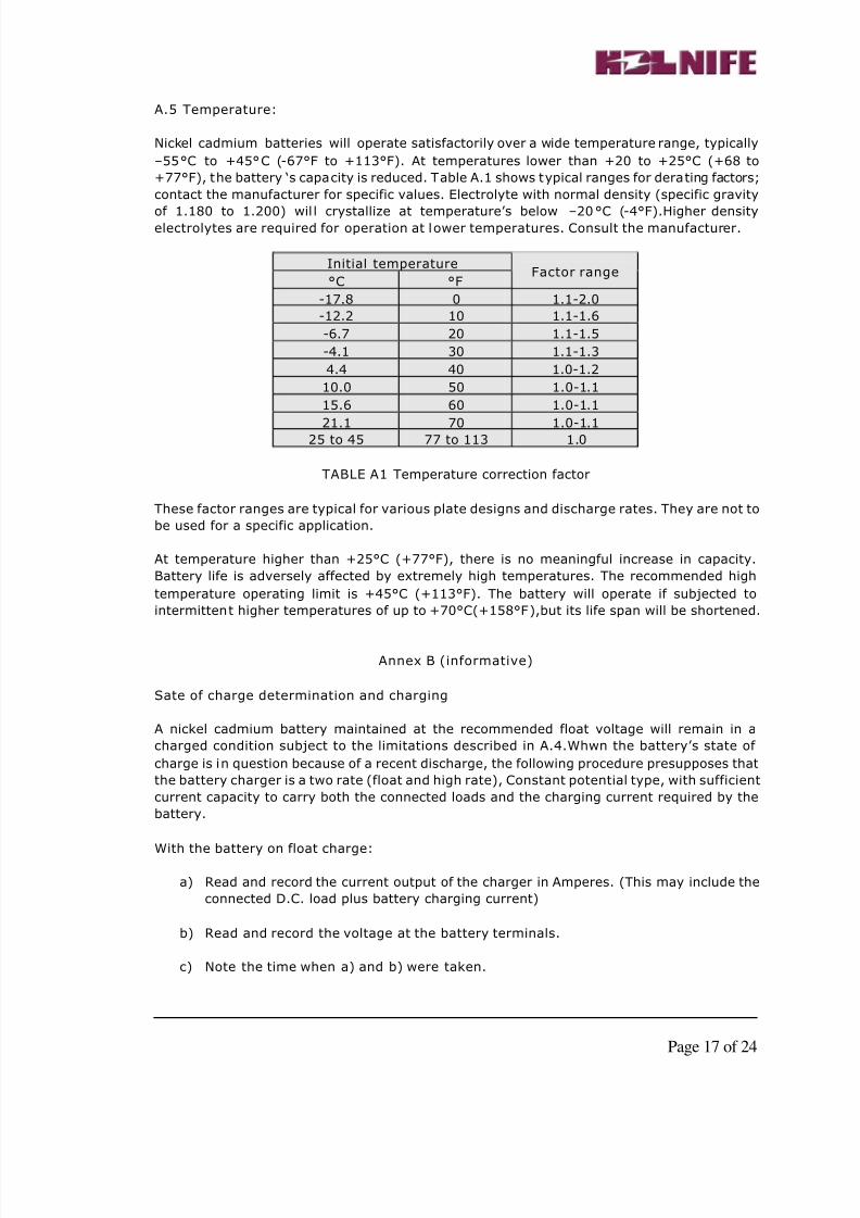
A.5 Temperature:
Nickel cadmium batteries will operate satisfactorily over a wide temperature range, typically
–55°C to +45°C (-67°F to +113°F). At temperatures lower than +20 to +25°C (+68 to
+77°F), the battery ‘s capacity is reduced. Table A.1 shows typical ranges for derating factors;
contact the manufacturer for specific values. Electrolyte with normal density (specific gravity
of 1.180 to 1.200) wil l crystallize at temperature’s below –20°C (-4°F).Higher densityelectrolytes are required for operation at lower temperatures. Consult the manufacturer.
Initial temperature
°C °FFactor range
-17.8 0 1.1-2.0
-12.2 10 1.1-1.6
-6.7 20 1.1-1.5
-4.1 30 1.1-1.3
4.4 40 1.0-1.2
10.0 50 1.0-1.1
15.6 60 1.0-1.1
21.1 70 1.0-1.125 to 45 77 to 113 1.0
TABLE A1 Temperature correction factor
These factor ranges are typical for various plate designs and discharge rates. They are not to
be used for a specific application.
At temperature higher than +25°C (+77°F), there is no meaningful increase in capacity.
Battery life is adversely affected by extremely high temperatures. The recommended high
temperature operating limit is +45°C (+113°F). The battery will operate if subjected to
intermittent higher temperatures of up to +70°C(+158°F),but its life span will be shortened.
Annex B (informative)
Sate of charge determination and charging
A nickel cadmium battery maintained at the recommended float voltage will remain in a
charged condition subject to the limitations described in A.4.Whwn the battery’s state of
charge is in question because of a recent discharge, the following procedure presupposes that
the battery charger is a two rate (float and high rate), Constant potential type, with sufficient
current capacity to carry both the connected loads and the charging current required by the
battery.
With the battery on float charge:
a) Read and record the current output of the charger in Amperes. (This may include the
connected D.C. load plus battery charging current)
b) Read and record the voltage at the battery terminals.
c) Note the time when a) and b) were taken.
8/4/2019 L9 NiCd Maintenance
http://slidepdf.com/reader/full/l9-nicd-maintenance 18/24
Page 18 of 24
Place the charger in the high-rate charge mode, and:
d) Read and record the current output of the charger [at least momentarily this will be
significantly higher than noted in a)]
e) Read and record the voltage at the battery terminals. Continue the high-rate charge
until the voltage reaches the high-rate maximum voltage previously established forthe system.
The state of charge may then be determined as follows:
1. If the high-rate charge voltage is reached in less than 1 minute and the current output
from the charger drops to approximately the float current found in a), the battery is
charged ;or
2. If the high-rate charge voltage is not reached rapidly, it indicates that the charger is in
current limit and that the battery is in need of a charge: or
3. If the charge current is unaccountably greater than the charge current output found in a),
the battery is in need of a charge.
NOTE: It is recommended that the high–rate charge, if required, be continued until such time
as the charge current is essentially the same as the current recorded in a). Normally no longer
than 72 h is required. At completion of high-rate charging, return the charger to float voltage.
Annex C (Informative)
Corrective actions
C.1 Low-voltage cell
If the voltage of an individual cell in a floating battery is found to be 1.35V or less, apply ahigh-rate charge. It may he more effective to apply the high-rate charge to the individual cell
concerned.
C.2 Water consumption
Unusual water Consumption is an indication of excessive charge voltage. When it becomes
necessary to add water, fill all cells to the maximum level with distilled or other approved-
quality water. Check the charger voltage setting at the battery terminals.
If the level of electrolyte has dropped so low as to expose plates, add water immediately. If
visual inspection shows no evidence of leakage, then high-rate charge the battery and test it
in accordance with the manufacturer’s recommendations
C.3 Low -voltage battery
If the total battery float voltage is found to be less than the manufacturer’s recommended
minimum value, the battery is not being charged properly. At 1.30 V per cell, the battery is in
a discharging state. Follow the instructions in annex B to determine the state of charge and
take corrective action.
8/4/2019 L9 NiCd Maintenance
http://slidepdf.com/reader/full/l9-nicd-maintenance 19/24
Page 19 of 24
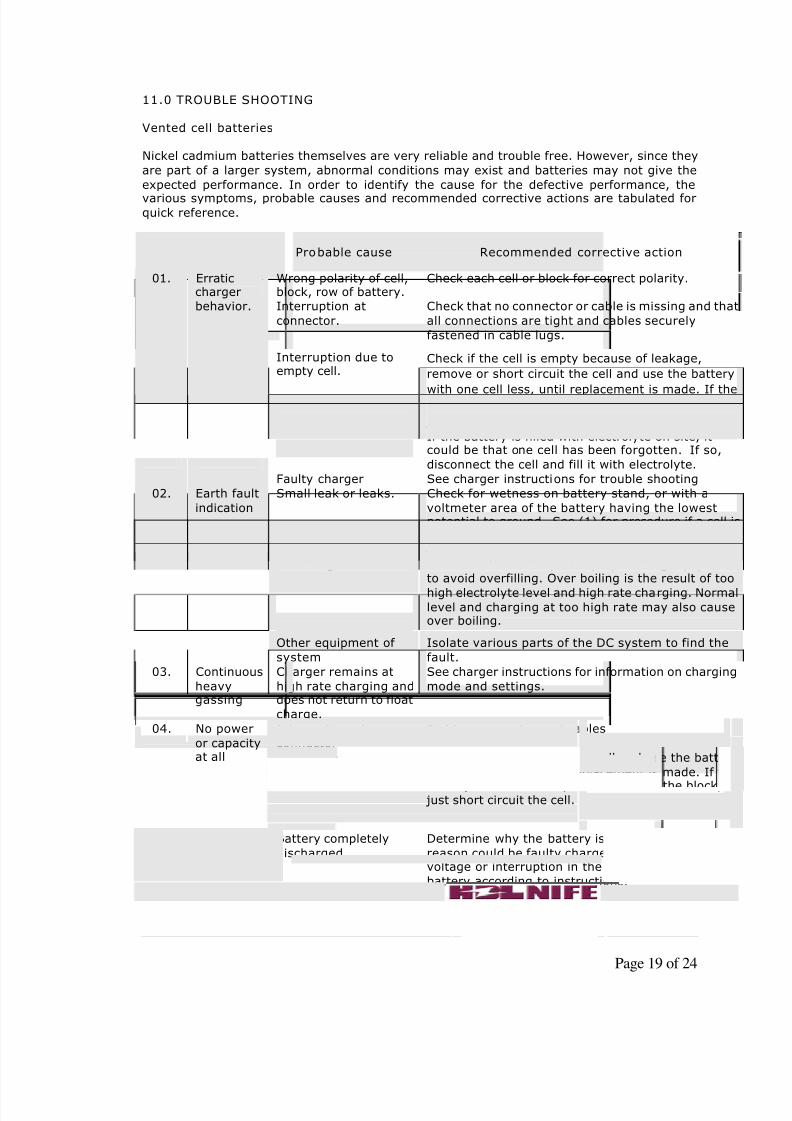
11.0 TROUBLE SHOOTING
Vented cell batteries
Nickel cadmium batteries themselves are very reliable and trouble free. However, since they
are part of a larger system, abnormal conditions may exist and batteries may not give the
expected performance. In order to identify the cause for the defective performance, the
various symptoms, probable causes and recommended corrective actions are tabulated forquick reference.
Sl.No. Symptom Probable cause Recommended corrective action
Wrong polarity of cell,block, row of battery.
Check each cell or block for correct polarity.
Interruption at
connector.
Check that no connector or cable is missing and that
all connections are tight and cables securely
fastened in cable lugs.
Check if the cell is empty because of leakage,
remove or short circuit the cell and use the battery
with one cell less, until replacement is made. If thecell is part of the block, do not remove the block,
just short circuit the cell.
Interruption due toempty cell.
If the battery is filled with electrolyte on site, itcould be that one cell has been forgotten. If so,
disconnect the cell and fill it with electrolyte.
01. Erraticcharger
behavior.
Faulty charger See charger instructions for trouble shooting
Small leak or leaks. Check for wetness on battery stand, or with a
voltmeter area of the battery having the lowestpotential to ground. See (1) for procedure if a cell is
leaking.
Battery wet due to
overfilling
Disconnect a few connectors to avoid high voltage
and clean the battery. Use proper filling equipmentto avoid overfilling. Over boiling is the result of too
high electrolyte level and high rate charging. Normallevel and charging at too high rate may also causeover boiling.
02. Earth fault
indication
Other equipment of
system
Isolate various parts of the DC system to find the
fault.
03. Continuous
heavygassing
Charger remains at
high rate charging anddoes not return to float
charge.
See charger instructions for information on charging
mode and settings.
Interruption at
connector
Tighten connector and cables
Interruption due to
empty cell
Remove or short circuit the cell and use the battery
with one cell less, until replacement is made. If the
cell is part of the block, do not remove the block, just short circuit the cell.
04. No power
or capacityat all
Battery completely
discharged.
Determine why the battery is discharged. The
reason could be faulty charger or fuse, wrong floatvoltage or interruption in the battery. Recharge the
battery according to instructions.
8/4/2019 L9 NiCd Maintenance
http://slidepdf.com/reader/full/l9-nicd-maintenance 20/24
Page 20 of 24
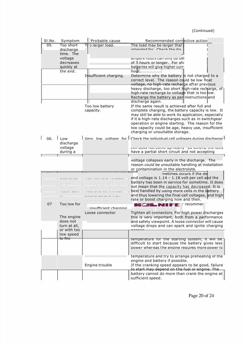
(Continued)
Sl.No. Symptom Probable cause Recommended corrective action
Too larger load. The load may be larger that what the battery was
intended for. Check the discharge against batteryperformance data. Note that the rated number of
ampere hours can only be delivered at discharges,
of 5 hours or longer. For short discharges,batteries will give higher currents but less ampere-
hour.
Insufficient charging. Determine why the battery is not charged to a
correct level. The reason could be low floatvoltage, no high-rate recharge after previous
heavy discharge, too short high-rate recharge, of high-rate recharge to voltage that is too low.
Recharge the battery as per instructions anddischarge again.
05. Too short
dischargetime. The
voltage
decreasesquickly at
the end.
Too low batterycapacity.
If the same result is achieved after full andcomplete charging, the battery capacity is low. It
may still be able to work its application, especially
if it is high-rate discharges such as in switchgearoperation or engine starting. The reason for the
low capacity could be age, heavy use, insufficientcharging or unsuitable storage.
06. Low
discharge
voltageduring a
major partof
discharge.
Very low voltage for
one or few cells.
Check the individual cell voltages during discharge
and full recharge. If the voltage of an individual
cell does not come up nearly as others, the cellshave a partial short circuit and not accepting
charge. If the charging voltage is fine but the cellvoltage collapses early in the discharge. The
reason could be unsuitable handling at installation
or contamination in the electrolyte.
06. Lowdischarge
voltageduring amajor part
of discharge.
Battery designed withhigh cell end voltage.
The dischargepreceded by long termfloat charge without
discharge and high-rate charges.
This condition sometimes occurs if the design cellend voltage is 1.14 – 1.18 volt per cell and the
battery has been in service for sometime. It doesnot mean that the capacity has decreased. It isbest handled by using more cells in the battery
and thus lowering the final cell voltages, and highrate or boost charging now and then.
Discharged battery dueto insufficient charging
Charge as per manufacturer recommendation.
Loose connector Tighten all connectors. For high power discharges
this is very important, both from a performance
and safety viewpoint. A loose connector will causevoltage drops and can spark and ignite charging
gasses.
Too low temperature If the temperature is lower than the design
temperature for the starting system, it will bedifficult to start because the battery gives less
power whereas the engine requires more power toturn. Use the correct engine oil for the
temperature and try to arrange preheating of the
engine and battery if possible.
07 Too low forengine
starting.The engine
does not
turn at all,or with too
low speedto fire
Engine trouble If the cranking speed appears to be good, failureto start may depend on the fuel or engine. The
battery cannot do more than crank the engine at
sufficient speed.
8/4/2019 L9 NiCd Maintenance
http://slidepdf.com/reader/full/l9-nicd-maintenance 21/24
Page 21 of 24
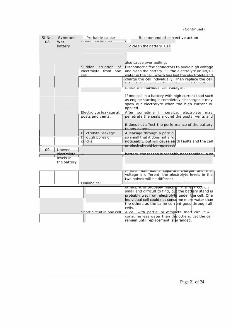
(Continued)
Sl.No. Symptom Probable cause Recommended corrective action
Overfilling or over
boiling
Disconnect a few connectors to avoid high voltage
and clean the battery. Use proper filling equipment
to avoid overfilling. Over boiling is the result of toohigh electrolyte level and high rate charging.
Normal level and charging at too high rate mayalso cause over boiling.
Sudden eruption of electrolyte from one
cell
Disconnect a few connectors to avoid high voltageand clean the battery. Fill the electrolyte or DM/DI
water in the cell, which has lost the electrolyte andcharge the cell individually. Then replace the cell
in the battery and recharge the complete battery.
Check the individual cell voltages.
If one cell in a battery with high current load suchas engine starting is completely discharged it may
spew out electrolyte when the high current isapplied.
Electrolyte leakage atposts and vents.
After sometime in service, electrolyte maypenetrate the seals around the posts, vents and
connectors. In the normal cleaning of the battery,it does not affect the performance of the battery
to any extent.
08 Wet
battery
Electrolyte leakage
through pores orcracks.
A leakage through a pore or small crack could be
so small that it does not affect the electrolyte levelnoticeably, but will cause earth faults and the cell
or block should be replaced.
Poor filling or topping
up.
If the levels of electrolyte vary throughout the
battery, the reason is probably poor topping up orleveling off after filling.
Different float voltages Batteries are often divided in two halves, which isgood from reliability and maintenance viewpoints.
If each half has a separate charger and thevoltage is different, the electrolyte levels in the
two halves will be different
Leaking cell If one cell has a lower electrolyte level than all the
others, it is probably leaking. The leak could besmall and difficult to find, but the battery stand is
probably wet from electrolyte under the cell. One
individual cell could not consume more water thanthe others as the same current goes through all
cells.
09 Uneven
electrolytelevels in
the battery
Short circuit in one cell A cell with partial or complete short circuit will
consume less water than the others. Let the cellremain until replacement is arranged.
8/4/2019 L9 NiCd Maintenance
http://slidepdf.com/reader/full/l9-nicd-maintenance 22/24
Page 22 of 24
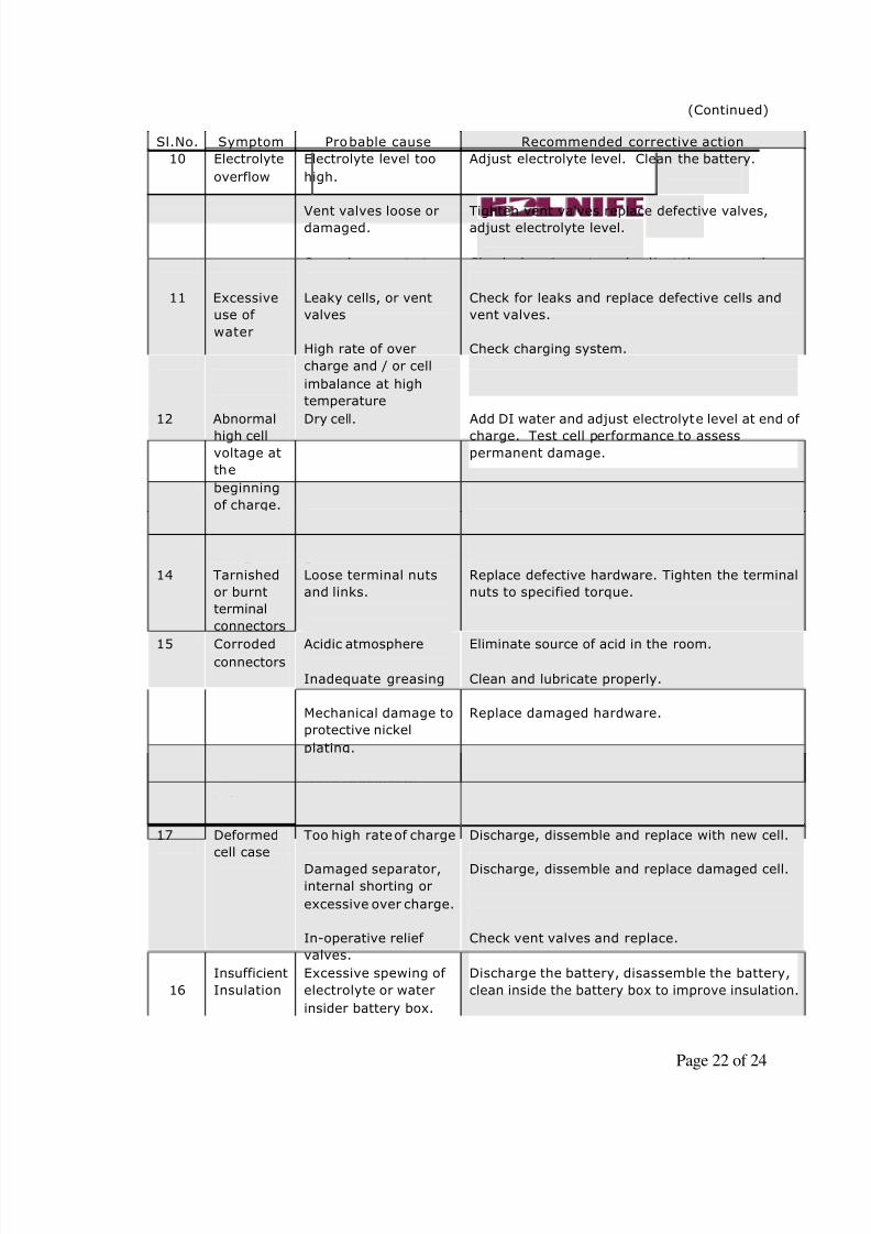
(Continued)
Sl.No. Symptom Probable cause Recommended corrective action
10 Electrolyte
overflow
Electrolyte level too
high.
Vent valves loose ordamaged.
Over charge rate too
high.
Adjust electrolyte level. Clean the battery.
Tighten vent valves replace defective valves,adjust electrolyte level.
Check charging rate and adjust the proper charge
rate.
11 Excessive
use of
water
Leaky cells, or vent
valves
High rate of over
charge and / or cell
imbalance at high
temperature
Check for leaks and replace defective cells and
vent valves.
Check charging system.
12 Abnormal
high cellvoltage at
the
beginning
of charge.
Dry cell. Add DI water and adjust electrolyte level at end of
charge. Test cell performance to assesspermanent damage.
13 Continuous
foaming on
charge.
Electrolyte
contaminated by oil or
grease.
Discharge the battery. Replace contaminated cells
and test.
14 Tarnished
or burnt
terminal
connectors
Loose terminal nuts
and links.
Replace defective hardware. Tighten the terminal
nuts to specified torque.
15 Corrodedconnectors
Acidic atmosphere
Inadequate greasing
Mechanical damage to
protective nickel
plating.
Eliminate source of acid in the room.
Clean and lubricate properly.
Replace damaged hardware.
16 Burnt or
pitted
battery
terminals
Improper contact or
loose connectors
Clean, repair and replace parts to mate properly.
17 Deformed
cell case
Too high rate of charge
Damaged separator,
internal shorting or
excessive over charge.
In-operative relief
valves.
Discharge, dissemble and replace with new cell.
Discharge, dissemble and replace damaged cell.
Check vent valves and replace.
16
Insufficient
Insulation
Excessive spewing of
electrolyte or water
insider battery box.
Discharge the battery, disassemble the battery,
clean inside the battery box to improve insulation.
8/4/2019 L9 NiCd Maintenance
http://slidepdf.com/reader/full/l9-nicd-maintenance 23/24
Page 23 of 24
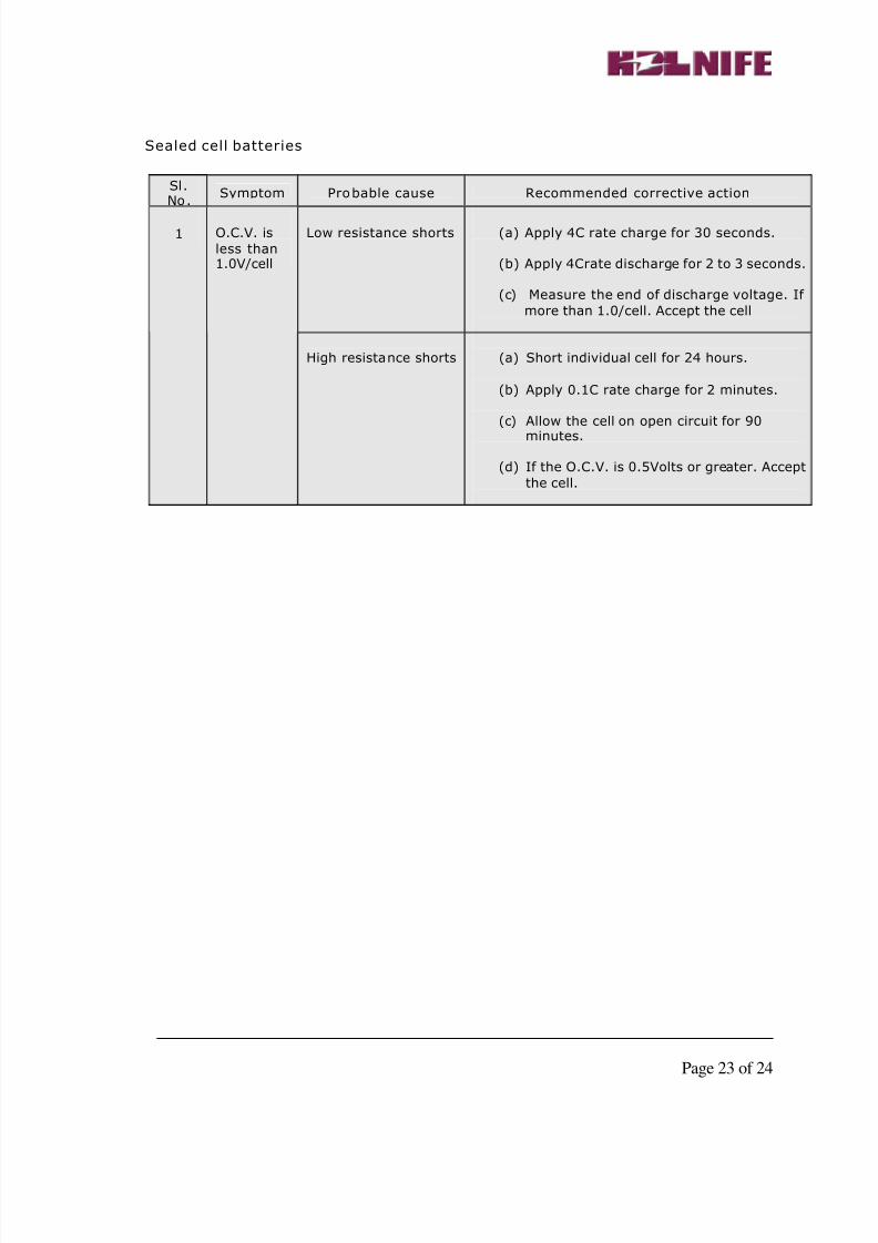
Sealed cell batteries
Sl.No.
Symptom Probable cause Recommended corrective action
Low resistance shorts (a) Apply 4C rate charge for 30 seconds.
(b) Apply 4Crate discharge for 2 to 3 seconds.
(c) Measure the end of discharge voltage. If
more than 1.0/cell. Accept the cell
1 O.C.V. is
less than1.0V/cell
High resistance shorts (a) Short individual cell for 24 hours.
(b) Apply 0.1C rate charge for 2 minutes.
(c) Allow the cell on open circuit for 90
minutes.
(d) If the O.C.V. is 0.5Volts or greater. Accept
the cell.
8/4/2019 L9 NiCd Maintenance
http://slidepdf.com/reader/full/l9-nicd-maintenance 24/24
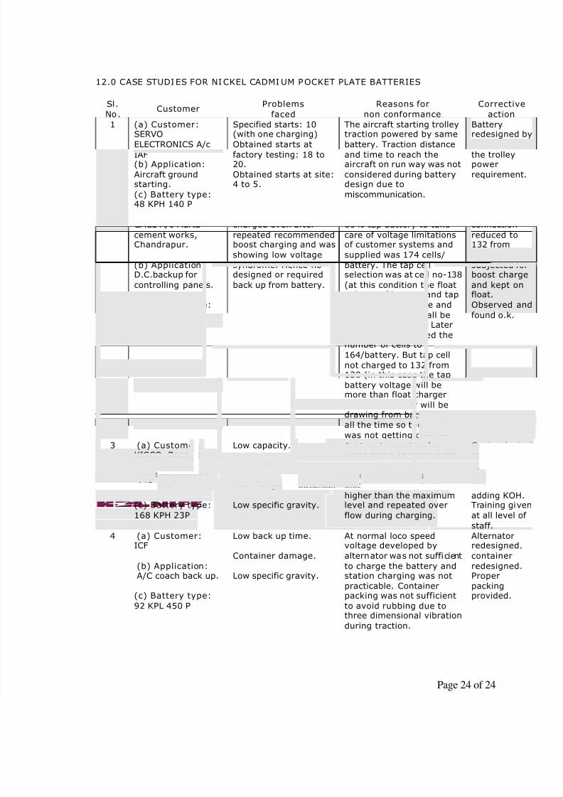
12.0 CASE STUDIES FOR NICKEL CADMI UM POCKET PLATE BATTERIES
Sl.
No.Customer
Problems
faced
Reasons for
non conformance
Corrective
action
1 (a) Customer: SERVO
ELECTRONICS A/c
IAF(b) Application:
Aircraft groundstarting.
(c) Battery type: 48 KPH 140 P
Specified starts: 10(with one charging)
Obtained starts at
factory testing: 18 to20.
Obtained starts at site:4 to 5.
The aircraft starting trolleytraction powered by same
battery. Traction distance
and time to reach theaircraft on run way was not
considered during batterydesign due to
miscommunication.
Batteryredesigned b
considering
the trolleypower
requirement.
2 (a) Customer: GACL A/c Marta
cement works,Chandrapur.
(b) Application:D.C.backup for
controlling panels.
(c) Battery type:
174 KPM 400P174 KPM 165P
Battery was not gettingcharged even after
repeated recommendedboost charging and was
showing low voltage
syndrome. Hence nodesigned or required
back up from battery.
Battery was designed with80% tap battery to take
care of voltage limitationsof customer systems and
supplied was 174 cells/
battery. The tap cellselection was at cell no-138
(at this condition the floatvoltage of battery and tap
battery will be same and
the system load shall befrom float charger). Later
on customer reduced thenumber of cells to
164/battery. But tap cell
not charged to 132 from138 (in this case the tap
battery voltage will bemore than float charger
hence the power will be
drawing from battery onlyall the time so the battery
was not getting charged.
Tap cellconnection
reduced to132 from
138.Battery
subjected forboost charge
and kept onfloat.
Observed an
found o.k.
3 (a) Customer:KISCO, Bangalore.
(b) Application:A/C ups
(c) Battery type:
168 KPH 23P
Low capacity.
Low voltage.
Low charge acceptance.
Low specific gravity.
Acid contamination byusing same apparatus for
lead acid and nickel
cadmium batteries.Electrolyte topping up
higher than the maximumlevel and repeated over
flow during charging.
Contaminatecells replaced
Specific
gravitycorrected by
adding KOH.Training give
at all level of
staff.
4 (a) Customer:ICF
(b) Application:A/C coach back up.
(c) Battery type:
92 KPL 450 P
Low back up time.
Container damage.
Low specific gravity.
At normal loco speedvoltage developed by
alternator was not sufficientto charge the battery andstation charging was not
practicable. Containerpacking was not sufficient
to avoid rubbing due tothree dimensional vibration
during traction.
Alternatorredesigned.
containerredesigned.Proper
packingprovided.