L16 usart-atmega328 p
19
Serial Communication in Atmega328P (Lecture-16) R S Ananda Murthy Associate Professor Department of Electrical & Electronics Engineering, Sri Jayachamarajendra College of Engineering, Mysore 570 006 R S Ananda Murthy Serial Communication in Atmega328P
-
Upload
rsamurti -
Category
Engineering
-
view
495 -
download
4
Transcript of L16 usart-atmega328 p

Serial Communication in Atmega328P(Lecture-16)
R S Ananda Murthy
Associate ProfessorDepartment of Electrical & Electronics Engineering,
Sri Jayachamarajendra College of Engineering,Mysore 570 006
R S Ananda Murthy Serial Communication in Atmega328P

Serial and Parallel Communication
Sender Receiver
Sender Receiver
D0
D7
:::::
D0D1..D7
Serial Communication
Parallel Communication
R S Ananda Murthy Serial Communication in Atmega328P

Serial versus Parallel Communication
Serial Communication
Bit-by-bit transmission.Requires parallel-to-serial conversion at the sending endand serial-to-parallel conversion at the receiving end.Requires lesser number of wires as compared to parallelcommunication.Serial high-speed communication is becoming possiblenow-a-days with improved hardware.RS232, RS485, SPI, USB, I2C and CAN – all thesemethods of communication employ serial communication.
Parallel Communication
Byte-by-byte transmission on eight data lines.Was popular in 1990s because of its then higher speed ascompared serial communication.Not suitable for long distance communication as number ofwires required is more.
R S Ananda Murthy Serial Communication in Atmega328P

Types of Serial Communication
Synchronous
Sender and receiver are driven by the same clock signal.SPI and I2C communication protocols are very commonexamples of synchronous serial communication.Transfers a block of data (several characters) in oneoperation.
Asynchronous
Sender and receiver are not driven by the same clocksignal.Sender and receiver have to agree to operate at the samebaud rate.Synchronization of sender and receiver is achieved byinserting START and STOP bits along with the data bits toform a data frame.Typically used to transmit a single character at a time.
R S Ananda Murthy Serial Communication in Atmega328P

Technical Terms Related to Serial Communication
Baud Rate Bits per second.Simplex One-way communication. For example, Device-1
can send data to Device-2 and not vice versa.Full-duplex Two-way communication. Device-1 and 2 can both
send and receive data simultaneously.Half-duplex Two-way communication, but not simultaneously.
USART Universal Synchronous Asynchronous ReceiverTransmitter. In most of the modern MCUs likeAtmega328P this block is integrated on the chip.
Data Frame Data bits along with START bit, STOP bit, andoptional parity bit is called a data frame.
Modem A device which converts 1s and 0s to audio tonesused for serial communication on telephone lines.
R S Ananda Murthy Serial Communication in Atmega328P

Data Frame
0 1 0 0 0 0 0Stop Start1
D0D1D2D3D4D5D6D7
Mark
Direction of transmission
Framing of ASCII Charater `A' (0x41) for serial communication
When there is no data transfer, the status of signal is 1(high) which is also referred to as Mark.Transmission begins with a Start bit which is 0 (low), alsocalled as Space.After this the data bits are transmitted in the order LSB toMSB and a STOP bit which is high (1).In some systems, a parity bit for even or odd parity isincluded in the data frame for data integrity.
R S Ananda Murthy Serial Communication in Atmega328P

RS232C Standard for Serial Communication
Proposed by Electronics Industries Association in 1960s.Widely used for short distance serial communication eventoday.As per this standard, a voltage in the range −3 V to −25 Vrepresents a logical high (1) and a voltage level in therange +3 V to +25 V represents a logical low (0).Since the voltage levels of this standard are not compatiblewith TTL levels used by MCUs such as Atmega328P, weneed to use a voltage converter chip such as MAX232 orMAX233.
R S Ananda Murthy Serial Communication in Atmega328P

MAX232 Converter Chip
R S Ananda Murthy Serial Communication in Atmega328P
PC Serial Port Communication with MAX232
R S Ananda Murthy Serial Communication in Atmega328P

Block Diagram of USART0 in Atmega328P
R S Ananda Murthy Serial Communication in Atmega328P

USART0 Pins of Atmega328P
TxD On this pin serial data is transmitted by theUSART0
RxD On this pin serial data is received by the USART0XCK This pin is used for clock signal only during
synchronous serial communication.
R S Ananda Murthy Serial Communication in Atmega328P

Serial Peripheral Interface (SPI)
SPIMaster
SPISlave
SDOMOSI
SDI
SDI SDO
SCLK SCLKSCK
CE CESS
MISO
MOSI – Master Out Slave In; MISO – Master In Slave Out;SCK – Serial Clock; SS – Slave Select
SPI interface is typically used for short distancecommunication between two devices.
R S Ananda Murthy Serial Communication in Atmega328P

Serial Peripheral Interface (SPI)
SPI, originally proposed by Motorola (now Freescale), usesfour wires – SDI (also called MOSI), SDO (also calledMISO), SCLK (also called SCK) , and CE (also called SS).In SPI, one device will be master and the other device/swill be slave/s.Master always starts the communication by activating SSand SCK.SPI Communication is full-duplex.In some systems SPI uses a common wire for bothMOSI/MISO, thus reducing the number of wires to three.But such systems follow a different protocol for datatransmission as compared to 4-wire SPI systems.
R S Ananda Murthy Serial Communication in Atmega328P
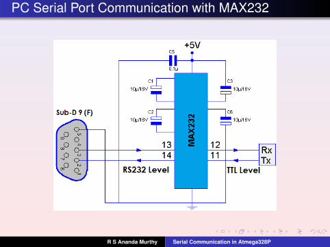
SPI Architecture
When master wants to send a byte it places it in its shiftregister and issues 8 clock pulses.Then, the contents of the shift registers in the master andslave are interchanged.Clock input to the shift registers can be falling- orrising-edge triggered.
R S Ananda Murthy Serial Communication in Atmega328P

SPI Modes of Operation
Write Operation (indicated by D7 = 1 of the first byte)
Single-byte – write a byte to the slave.Multi-byte – write multiple bytes to the slave.
Read Operation (indicated by D7 = 0 of the first byte)
Single-byte – read a byte from the slave.Multi-byte – read multiple bytes from the slave
Multi-byte operations are also known as burst mode operations.
R S Ananda Murthy Serial Communication in Atmega328P

Single-byte SPI Write Operation
1 Master places the bit pattern 1A6A5A4A3A2A1A0 in its shiftregister, makes SS = 0 to select the slave, and then issues8 pulses of SCK to transfer it to the slave on the MOSI line.
2 Master issues 8 more pulses of SCK to shift a byte of datato the slave on the MOSI line and then makes SS = 1 todeselect the slave.
R S Ananda Murthy Serial Communication in Atmega328P

Single-byte SPI Read Operation
1 Master places the bit pattern 0A6A5A4A3A2A1A0 in its shiftregister, makes SS = 0 to select the slave, and then issues8 pulses of SCK to transfer it to the slave on the MOSI line.
2 Master issues 8 more pulses of SCK to shift a byte of datafrom the slave on the MISO line and then makes SS = 1 todeselect the slave.
R S Ananda Murthy Serial Communication in Atmega328P

SPI Burst Mode Operations
SPI Burst Mode Write Operation
SPI Burst Mode Read Operation.
In this mode, the address is automatically updated in the slaveand the byte count is maintained in the master.
R S Ananda Murthy Serial Communication in Atmega328P

License
This work is licensed under aCreative Commons Attribution 4.0 International License.
R S Ananda Murthy Serial Communication in Atmega328P


![AT11626: SAM D SERCOM USART Configurationww1.microchip.com/.../Atmel-42539-SAMD-SERCOM-USART-Configuration... · AT11626: SAM D SERCOM USART Configuration [APPLICATION NOTE] 3 Atmel-42539A-SAMD-SERCOM-USART-Configuration_ApplicationNote_AT11626_092015](https://static.fdocuments.net/doc/165x107/5e8569d49b115e518a2fc952/at11626-sam-d-sercom-usart-at11626-sam-d-sercom-usart-configuration-application.jpg)