L Led guide - zumtobel.com · PANOS 150 LED 2LIGHT Mini LED SCONFINE CUBO PASO II Led teChnoLoGY 7....
28
Design, planning and installation guide with tips and tricks for the use of LED installations. LED power supply unit LED guide
Transcript of L Led guide - zumtobel.com · PANOS 150 LED 2LIGHT Mini LED SCONFINE CUBO PASO II Led teChnoLoGY 7....

P r o d u k t n a m e S e i t e n t h e m a 1
Design, planning and installation guide with tips and tricks for the use of LED installations.
K211
LED module
LN
DALI
LED module
LED module
-R
-B-G
C004PWM amplifier–Ch 1
–Ch 3–Ch 2
+Ch 1-3
+Uin–Uin
–Ch 1
–Ch 3
–Ch 2
+Ch 1-3
C004PWM amplifier–Ch 1
–Ch 3–Ch 2
+Ch 1-3
+Uin–Uin
–Ch 1
–Ch 3
–Ch 2
+Ch 1-3
Max. 40 C004 PWM amplifiers per C003
C001PWM dimmer+Ch 1
+Ch 3+Ch 2
–Ch 1-3
+Uin–Uin
–Ch 1
–Ch 3
–Ch 2
+Ch 1-3
0–10 V
0–10 V0–10 V
LED power supply unit
LN
12–24 VDC (SELV *)
C003DALI RGB controller
DADA
+ U– U
–Ch 1
–Ch 3
–Ch 2
+Ch 1-3
DALI
Max. 15 C004 PWM amplifiers per K210
C004PWM amplifier–Ch 1
–Ch 3–Ch 2
+Ch 1-3
+Uin–Uin
–Ch 1
–Ch 3
–Ch 2
+Ch 1-3
Max. 120 C004 PWM amplifiers per C001
+Ch 1
+Ch 3+Ch 2
–Ch 1-3
+Uin–Uin
100
K / O
HM li
near
LED luminaire/LED module
LED luminaire/LED module
LED luminaire/LED module
LED luminaire/LED module
LED luminaire/LED module
LED luminaire/LED module
LED luminaire/LED module
LED luminaire/LED module
LED luminaire/LED module
LED luminaire/LED module
LED luminaire/LED module
LED luminaire/LED module
LED luminaire/LED module
LED luminaire/LED module
LED luminaire/LED module
Led guide


3C o n t e n t S
LED technology What is LED? 4
Advantages and limitations of LED 5
LED luminaire types 6
Application overview Application possibilities for LEDs 8
Design, planning and 5 criteria check 11
installation aids Cable lengths / cross-sections 12
Basic arrays of LED installations 13
LED power supply units 15
Dimmable LED power supply units and control units 16
LED constant current power supply units 18
Dimmable LED constant current power supply units and
control units 19
Wiring diagrams for electricians 20
Anwendungsbereiche Useful accessories 23
Tips and tricks 24
FAQs 25

What is Led ?
Zumtobel has always been known as a pioneer of LED technology and utilises it for a wide variety of applications for indoor and out-door lighting, in both decorative and functional areas. Constantly increasing levels of luminous flux and the development of efficient optical systems open the way for ever more interesting lighting solu-tions for light projection applica-tions. An impressive example is the lighting stage set at the new FIFA headquarters in Zurich. Depending upon application and required lighting technology, three different types of LED were installed.
Chip-on-Board LEDsAfter the LED chip is bonded directly onto the board and is con-tacted via the “bond wires”, a bonded epoxy lens, the so-called “bubble”, defines light distribution. According to the design of the bubble, a COB LED can have extremely narrow-beam or extremely wide-angle distribution.
SMD LEDs (Surface Mounted Device LEDs)These are bonded onto the sur-face of the printed circuit board and are contacted in the soldering bath. The linear LED board in KAVA LED, for example, is equipped with LEDs featuring SMD construction.
White LED light can be created by two processes: firstly by RGB colour mixing, where a neutral, somewhat indefinable white is created when the “colour triangle” is passed through. The second, standard process for creation of white LED light is based upon the principle of luminescence con-version.
A fluorescent layer similar to that found in a fluorescent lamp is incorporated above a blue LED chip, so that a part of the light band is converted into white light. According to the composition of the conversion substance, colour temperature ranges from warm to cool white.
Fluorescent principle or luminescence conversion
BubbleWire bond
LED chip
Printed circuit board
High current LEDs As part of the continuous devel-opment of LEDs for lighting indus-try purposes, focus is being increasingly shifted from decora-tive lighting applications to illumi-nation. The LED chip must be come significantly larger. In order to achieve full output, power supply is not 10–30 mA as with
the small chips, but from 350 to over 700 mA, demanding a com-pletely new LED design. High cur-rent LEDs are integrated within a heat sink that is able to take up the heat from the chip very effi-ciently and transfer it directly to a larger cooling surface.

Long service lifeAccording to design, LEDs achieve a service life of up to 50 000 hours and more. This translates into long maintenance intervals.
Low energy consumptionAs part of the CO2 debate, energy efficiency is becoming increas-ingly important. The luminous flux per watt of today‘s LED genera-tions is well above that of low volt-age halogen luminaires, and according to colour temperature is currently between 40–80 lm/W.
Gentle lightLEDs develop low levels of heat on luminaire surfaces because of their UV/IR-free light, making them ideal for conservational lighting.
White LED lightColour temperatures ranging between warm and cool can be generated today with standard-ised types of LED.
Coloured and dynamic lightLEDs create light directly in differ-ent colours. Coloured LEDs can be combined into clusters and controlled in order to generate colour mixes and dynamic colour sequences (RGB tech nology).
Control of LEDsLEDs are semiconductor devices that can be efficiently dimmed or dynamically controlled.
Benefits of LED technology compared to low voltage halo-gen Compared to low voltage halogen, one of the main advantages is IR/UV-free light and its absence of heat radiation. The energy effi-ciency of LEDs is much higher than that of low voltage halogen luminaires.
Benefits of LED technology compared to fluorescent lamps Advantages compared to fluores-cent lamps are somewhat less. In addition to conservational lighting and long maintenance intervals, the main benefit of LEDs is pro-jected light. Lens optics allow optimal light direction onto the targeted area, allowing illumination output to be much more efficiently imple-mented. In addition, cove lighting in dynamic colours with RGB LED solutions, for example, can be created space-savingly and with a high level of efficiency.
Further benefits:n Saturated coloursn Optimal operation at low
temperaturesn Resistance to vibration and
impact
Energy efficiency levels for LED are at present lower than with the following lamp technologies:– Fluorescent lamps:
80–100 lm/W– High pressure halogen lamps:
90–100 lm/W– High pressure sodium
vapour lamps: 100–120 lm/W– LED: 40–80 lm/W
LEDs are not at ease with high ambient temperatures, and in these conditions (in saunas for example), luminous flux and serv-ice life of the LEDs are negatively affected.
The board of high output LEDs becomes very hot. In order to ensure a luminaire service life of 50 000 hours, the board must be efficiently cooled (e.g. with cooling ribs, fan cooling or water cooling).
Benefits Limitations
5L e d t e C h n o L o G Yadvantages and limitations of Led

Led luminaire types
Voltage-controlled luminaires with 24 V Current-controlled luminaires with 350 mA
Zumtobel luminaire rangesLEDOS MLEDOS BLEDOS recessed floor luminairesLEDOS IIKAVA LEDSYSTEMLED DECO/FLOOD
Power LEDse.g.: ORILED, PANOS S 100 LED, PASO II RGB
Conventional LEDs e.g.: LEDOS, KAVA, SYSTEMLED DECO
Decorative applicationse.g.: light points, light lines.
Luminaires are measured in volts and wattsThe number of luminaires per control gear unit depends upon their total output (watt/ampere).
e.g.: 24 V, 25 W power supply unit SYSTEMLED DECO each 10 W (= 1007 mm), 2 W (= 207 mm) 1 24 V, 25 W power supply unit
for max. 2 SYSTEMLED each 10 W, and 2 SYSTEMLED each 2 W
Luminaires are connected in PARALLEL
Zumtobel luminaire rangesORILED 350 mAPASO II RGB PANOS S 100 LED
Luminaires are connected in SERIES
Luminaires are measured in volts and wattsThe number of current-controlled LEDs per control gear unit depends upon the respective wattage and current available to that control gear unit. According to manufacturer, current-controlled LEDs require a current of up to 4 volts.
e.g.: 350 mA constant current power supply unit, 24 V / 8 W on the secondary side.
3 x 2.5 W = 7.5 W6 x 4 V = 24 V
1 350 mA constant current power supply unit
3 ORILED, each 2.5 W (2 LEDs, each 4 V).
Decorative applications / projected lighte.g.: light cone, directional light.
➔
➔➔
➔

Luminaires with 230 V
Propertiesn Number of luminaires
unlimited.n Easy planning/installation.
230 V LED luminaires are generally not dimmable / regulable. Exceptions are luminaires having a separate control input or control button. e.g.: ORILED 230 V PHAOS Line RGB PANOS 150 LED 2LIGHT Mini LED
Zumtobel luminaire rangesLEDOS MLEDOS BLEDOS recessed floor luminairesLEDOS IIPHAOS lineORILED 230 VPANOS 150 LED2LIGHT Mini LEDSCONFINE CUBOPASO II
7L e d t e C h n o L o G Y

Panos PureWhite
Panos BioMotion
Panos s
2Light Mini RgB/W
2Light Mini Pure Wh.
ViVo LED
MiCRos
suPERsystEM
typical applications Properties supply switchable/ Monochrome/ indoor/outdoor Product dimmable* RgB applications
application possibilities for Leds Typical lighting solutions and product categories
n 300 lm projected lightn 3000 K and 4700 K colour temperatures
n System combines miniaturised LED spots for accent lighting with T16 fluorescent lamps for wallwashing
n LED light lines for room illumination and atmo spheric lighting effects
* with 24 V and 350 mA luminaires, dimmability is dependent upon type of control gear!
n 1000 lm and 2000 lm as an alternative to 18 W / 26 W compact fluorescent lamps
n Colour temperatures of 3000 K (from February 09) and 4000 K (from November 08)
n 1000 lm projected lightn Colour temperature adjustable from 2700–6500 Kn RGB colour dynamism via EMOTION touch panel or DMXn Availability planned for November 2008
n Swivelling recessed downlights for decorative accent lighting
n 350 lm projected light as an alternative to 20 W low voltage halogen
n Indirect RGB light for “mellow downlight” effect in dynamic colours
n 1000 lm as an alternative to 18 W compact fluorescent lamps
n Colour temperatures of 3000 K (from February 09) and 4000 K (from November 08)
n 1100 lm projected light with 3000 Kn 1300 lm projected light with 4000 Kn Projected LED accent light as an alternative to 75 W
low voltage halogenn Available from spring 2009
dimmable DALI (via Emotion touch panel)
switchable, dimmable DALI
switchable, dimmable DALI (from February 2009)
switchable, dimmable
switchable, dimmable DALI (from February 2009)
control of white light via RGBRGB
RGB + white
white
whiteblue
white
white
indoor applications
indoor applications
indoor applications
indoor applications
indoor applications
indoor applications230 V
230 V
230 V
230 V
24 V
350 mA
switchable, dimmable DALI (via Emotion touch panel)
24 V230 V
24 V switchable, dimmable
switchable, dimmable
whiteRGB (light lines)
white
indoor applications
indoor applications

sConfinE CuBo
sConfinE sfERa
oRiLED
systEMLED fLooD
systEMLED DECo
LEDos M
LEDos B
LEDos
typical applications Properties supply switchable/ Monochrome/ indoor/outdoor Product dimmable* RgB applications
* with 24 V and 350 mA luminaires, dimmability is dependent upon type of control gear!
n Illuminance in accordance with EN 1838 for additional emergency lighting close to ground level
n Unique lens/reflector optic ensures optimal light distribution on the floor
n 3000 K / 5400 K available
switchable
switchable, dimmable
switchable, dimmable
switchable, dimmable
switchable, dimmable
switchable, dimmable
monochrome
white
whiteblueRGB
yellowredgreenwhiteblue
whiteblueRGB
whiteblue
indoor applications
indoor applications
indoor applicationsoutdoor applications
indoor applicationsoutdoor applications
indoor applicationsoutdoor applications
indoor applicationsoutdoor applications
230 V
24 V
230 V350 mA
230 V
230 V24 V
24 V
n Single and nine-fold modulesn Nine-fold modules feature dynamic light design
whereby the individual lighting cubes can be randomly dimmed up and down
n Colour temperature via control button in six pre-defined steps from 2700–6500 K
n Luminaire is part of the SCONFINE pendant luminaire series
n Modular LED light line system for individual, slot and channel mounting
n Not suitable for installation in floors!
n Modular LED light line system for individual, slot and channel mounting
n SYSTEMLED Deco Basic optimised for cove lightingn Not suitable for installation in floors!
n IP68 version for underwater lightingn Walk-over capacity to max. 1000 kg
9a P P L i C a t i o n o V e r V i e W
n Accent spotlight (spot/flood)n Walk-over capacity to max. 1000 kg
whiteblueRGB
indoor applicationsoutdoor applications
n 3000 K / 5700 K availablen Uniformly illuminated light points or surfacesn Walk-over capacity to max. 1000 kg
230 V24 V350 mA
230 V24 V
switchable, dimmable
switchable, dimmable
whiteblueRGB
indoor applicationsoutdoor applications

Phaos LinE
Paso ii LED
typical applications Properties supply switchable/ Monochrome/ indoor/outdoor Product dimmable* RgB applications
* with 24 V and 350 mA luminaires, dimmability is dependent upon type of control gear!
n Extremely easy wiring via self-tapping cable connector for indoor applications
n Walk-over capacity to max. 500 kgn RGB models feature integrated DALI power supply unitn Also available as a wall-mounted version
230 V24 V
230 V
switchable, dimmable
switchable, RGB dimmable DALI
yellowredgreenwhiteblueRGB
whiteblueRGB
indoor applicationsoutdoor applications
indoor applicationsoutdoor applications
n Diffuser with transparent sides gives the luminaire unit a floating appearance
n Model without frame also available
230 V24 V
switchable, dimmable
whiteblueRGB
indoor applicationsoutdoor applications
n “Glass only” model available for indoor applicationsn Walk-over capacity to max. 1000 kg
230 V24 V350 mA
switchable, dimmable
whiteblueRGB
indoor applicationsoutdoor applications
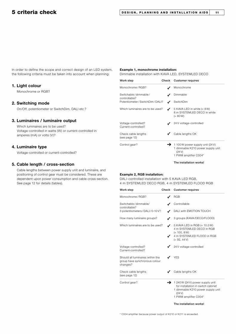
5 criteria check
In order to define the scope and correct design of an LED system, the following criteria must be taken into account when planning:
5. Cable length / cross-section
Example 1, monochrome installation:Dimmable installation with KAVA LED, SYSTEMLED DECO
✓Monochrome / RGB?
Switchable / dimmable / controllable?Potentiometer / SwitchDim / DALI?
Which luminaires are to be used?
Voltage-controlled? Current-controlled?
Check cable lengths (see page 12)
Control gear?
Monochrome
Dimmable
SwitchDim
5 KAVA LED in white (= 8 W)8 m SYSTEMLED DECO in white (= 80 W)
24 V voltage-controlled
Cable lengths OK
1 100 W power supply unit (24 V) 1 dimmable K210 power supply unit
(24 V)1 PWM amplifier C004*
The installation works!
Work step Check Customer requires
✓
✓✓
✓
➔
Example 2, RGB installation:DALI-controlled installation with 5 KAVA LED RGB, 4 m SYSTEMLED DECO RGB, 4 m SYSTEMLED FLOOD RGB
✓Monochrome / RGB?
Switchable / dimmable/ controllable?3 potentiometers / DALI / 0-10 V?
How many luminaire groups?
Which luminaires are to be used?
Voltage-controlled? Current-controlled?
Should all luminaires within the group have synchronous colour changes?
Check cable lengths (see page 12)
Control gear?
RGB
Controllable
DALI with EMOTION TOUCH
3 groups (KAVA/DECO/FLOOD)
5 KAVA LED in RGB (= 10.5 W)4 m SYSTEMLED DECO in RGB (= 100, 8 W)4 m SYSTEMLED FLOOD in RGB (= 92, 44 V)
24 V voltage-controlled
YES
Cable lengths OK
1 240 W (24 V) power supply unit for installation in switch cabinet
1 dimmable K210 power supply unit (24 V)
1 PWM amplifier C004*
The installation works!
Work step Check Customer requires
✓
✓
✓
✓
✓
✓
✓
✓
Monochrome or RGB?
On/Off, potentiometer or SwitchDim, DALI etc.?
Which luminaires are to be used? Voltage-controlled in watts (W) or current-controlled in amperes (mA) or volts (V)?
Voltage-controlled or current-controlled?
Cable lengths between power supply unit and luminaire, and positioning of control gear must be considered. These are dependent upon power consumption and cable cross-section. See page 12 for details (tables).
1. Light colour
2. Switching mode
3. Luminaires / luminaire output
4. Luminaire type
✓
➔
* C004 amplifier because power output of K210 or K211 is exceeded.
11d e S i G n , P L a n n i n G a n d i n S t a L L a t i o n a i d S
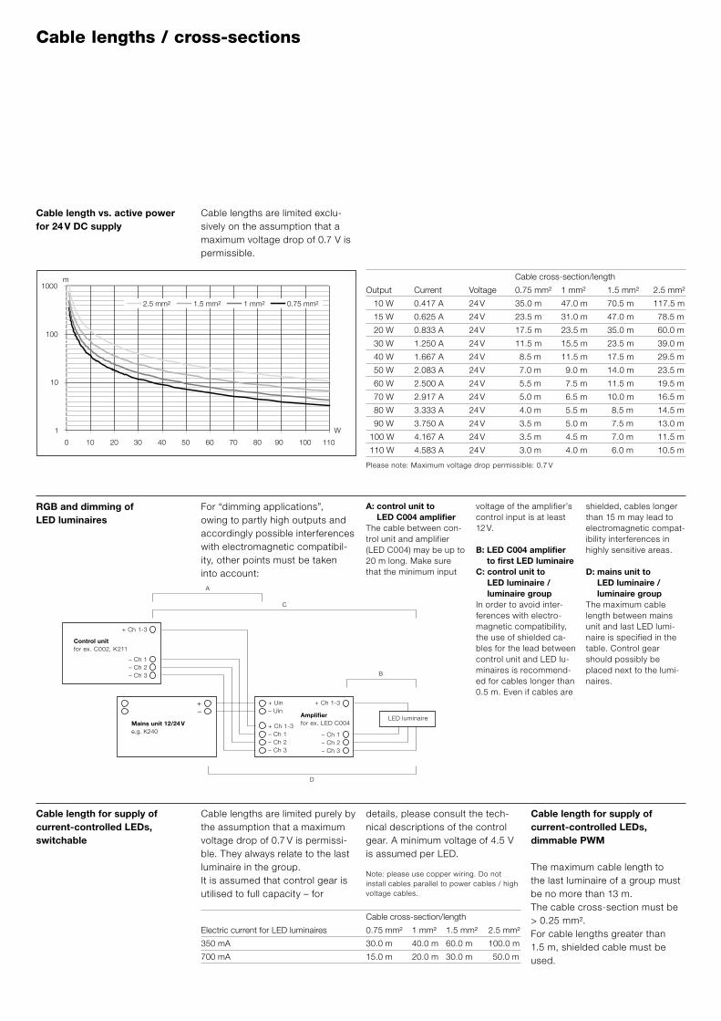
A: control unit to LED C004 amplifier
The cable between con-trol unit and amplifier (LED C004) may be up to 20 m long. Make sure that the minimum input
voltage of the amplifier’s control input is at least 12 V.
B: LED C004 amplifier to first LED luminaire
C: control unit to LED luminaire / luminaire group
In order to avoid inter-ferences with electro-magnetic compatibility, the use of shielded ca-bles for the lead between control unit and LED lu-minaires is recommend-ed for cables longer than 0.5 m. Even if cables are
shielded, cables longer than 15 m may lead to electromagnetic compat-ibility interferences in highly sensitive areas.
D: mains unit to LED luminaire / luminaire group
The maximum cable length between mains unit and last LED lumi-naire is specified in the table. Control gear should possibly be placed next to the lumi-naires.
RGB and dimming of LED luminaires
For “dimming applications”, owing to partly high outputs and accordingly possible interferences with electromagnetic compatibil-ity, other points must be taken into account:
Cable length for supply of current-controlled LEDs, switchable
Cable lengths are limited purely by the assumption that a maximum voltage drop of 0.7 V is permissi-ble. They always relate to the last luminaire in the group.It is assumed that control gear is utilised to full capacity – for
details, please consult the tech-nical descriptions of the control gear. A minimum voltage of 4.5 V is assumed per LED.
Note: please use copper wiring. Do not install cables parallel to power cables / high voltage cables.
Cable length for supply of current-controlled LEDs, dimmable PWM
The maximum cable length to the last luminaire of a group must be no more than 13 m. The cable cross-section must be > 0.25 mm². For cable lengths greater than 1.5 m, shielded cable must be used.
Cable lengths / cross-sections
1
10
100
1000
0 20 40 60 80 10010 30 50 70 90 110
0.75 mm21 mm21.5 mm22.5 mm2
m
W
B
C
D
A
+ Ch 1-3
– Ch 1– Ch 2– Ch 3
+–
+ Uin– Uin
+ Ch 1-3– Ch 1– Ch 2– Ch 3
+ Ch 1-3
– Ch 1– Ch 2– Ch 3
Amplifierfor ex. LED C004Mains unit 12/24 V
e.g. K240
Control unitfor ex. C002, K211
LED luminaire
Cable cross-section/length
Electric current for LED luminaires 0.75 mm² 1 mm² 1.5 mm² 2.5 mm²
350 mA 30.0 m 40.0 m 60.0 m 100.0 m
700 mA 15.0 m 20.0 m 30.0 m 50.0 m
Cable length vs. active power for 24 V DC supply
Cable lengths are limited exclu-sively on the assumption that a maximum voltage drop of 0.7 V is permissible.
Cable cross-section/length Output Current Voltage 0.75 mm² 1 mm² 1.5 mm² 2.5 mm²
10 W 0.417 A 24 V 35.0 m 47.0 m 70.5 m 117.5 m
15 W 0.625 A 24 V 23.5 m 31.0 m 47.0 m 78.5 m
20 W 0.833 A 24 V 17.5 m 23.5 m 35.0 m 60.0 m
30 W 1.250 A 24 V 11.5 m 15.5 m 23.5 m 39.0 m
40 W 1.667 A 24 V 8.5 m 11.5 m 17.5 m 29.5 m
50 W 2.083 A 24 V 7.0 m 9.0 m 14.0 m 23.5 m
60 W 2.500 A 24 V 5.5 m 7.5 m 11.5 m 19.5 m
70 W 2.917 A 24 V 5.0 m 6.5 m 10.0 m 16.5 m
80 W 3.333 A 24 V 4.0 m 5.5 m 8.5 m 14.5 m
90 W 3.750 A 24 V 3.5 m 5.0 m 7.5 m 13.0 m
100 W 4.167 A 24 V 3.5 m 4.5 m 7.0 m 11.5 m
110 W 4.583 A 24 V 3.0 m 4.0 m 6.0 m 10.5 m
Please note: Maximum voltage drop permissible: 0.7 V

Dim
min
gO
n/O
ff
Basic arrays of Led installations
LED mains unit
LEDOS 24 V
SYSTEMLEDDeco
SYSTEMLEDFlood
KAVA LED24 V
MICROS LED24 V
Mains 24 V-DC
K210
LEDOS 24 V
SYSTEMLEDDeco
SYSTEMLEDFlood*
KAVA LED24 V
Mains24 V-DC PWM
Monochrome LED luminaires, 24 V voltage-controlled
DALI/DSI/switchDIM
LED mains unit
LEDOS 24 V
SYSTEMLEDDeco
SYSTEMLEDFlood*
KAVA LED24 V
Mains 24 V-DC
C001Max. 3 POTI 100 K/Ohm linearor max. 3 x control voltage 0–10 V
24 V-DC PWM
LED mains unit
Mains 24 V-DC
24 V RGB LED luminaires in dynamic colours
K211
LEDOS 24 VRGB
SYSTEMLEDDeco RGB
KAVA LED RGB
SYSTEMLEDFlood RGB*
Mains24 V-DC PWM
LEDOS 24 VRGB
SYSTEMLEDDeco RGB
SYSTEMLEDFlood RGB*
KAVA LED RGB
LED mains unit
Mains
C0013 POTI 100 K/Ohm linearor 3 x control voltage 0–10 V
24 V-DC PWM
LEDOS 24 VRGB
SYSTEMLEDDeco RGB
SYSTEMLEDFlood RGB*
KAVA LED RGB
LED mains unit
Mains
DALI
24 V-DC PWM
LEDOS 24 VRGB
SYSTEMLEDDeco RGB
SYSTEMLEDFlood RGB*
KAVA LED RGB
LED mains unit
Mains
C003
1 POTI 100 K/Ohm linear
24 V-DC PWM
DALI
24 V-DC
24 V-DC
24 V-DC
Mains
LED mains unit
24 V-DC
C002
* These luminaires must be additionally supplied with 24 V DC supply voltage!
* These luminaires must be additionally supplied with 24 V DC supply voltage!
Co
lou
r se
qu
ence
can
be
sele
cted
wit
h D
AL
I, 0
-10
VA
uto
mat
ic c
olo
ur
seq
uen
ce
wit
h se
qu
ence
r
13d e S i G n , P L a n n i n G a n d i n S t a L L a t i o n a i d S

LEDOS 24 Vmono/RGB
SYSTEMLEDDeco
mono/RGB
KAVA LED mono/RGB
LED mains unit
Mains
C004PWM control signal(e.g. C001, C002, C003, K210, K211)
24 V-DC PWM
Application C004 PWM amplifier for controlling LED objects with higher output
LED mains unit(constant current)
LEDOS B350 mA
ORILED350 mA
PANOS S 100 LED 350 mA
Mains 350 mA
LED mains unit(constant current)
dimmable via PWM
Mains350 mA PWM
350 mA monochrome LED luminaires, current-controlled
PWM control signal(e.g. C001, K210)
LEDOS B350 mA
ORILED350 mA
PANOS S 100 LED 350 mA
LEDOS B RGB
350 mA
PASO II RGB350 mA
LED mains unit
Mains
C350 PWM dimmerPWM control signal(e.g. C001, C002, C003, K211)
350 mA PWM
LEDOS B RGB
350 mA
PASO II RGB350 mA
Mains
24 V-DC
24 V-DC
K350 DALI RGBConstant-current
converter
DALI
350 mA PWM
350 mA RGB LED luminaires in dynamic colours, current-controlled
The C004 amplifier is used where the luminaire output is higher than the output power of the control unit used.
Dim
min
gO
n/O
ffA
uto
mat
ic c
olo
ur s
eque
nce
with
seq
uenc
er, D
ALI
0-1
0 V
Basic arrays of Led installations

LED luminaire / LED module
LED power supply unit
LN
Led power supply units
n Input voltage range 100–264 V AC / 120–240 V DC
n Output voltage 24 V DC (SELV)
n Power output 10–100 W
n Protection type IP67n Protection class IIn Overtemperature
protection
n Short-circuit breaking with automatic restart
n Connecting cable with wire end sleeves, length approx. 2.0 m
8 W or 25 W LED power supply unit (S7 003 150, S7 003 230)n Input voltage 230 V ACn Output voltage 24 V DC
(SELV)n Power output 8 W or
25 Wn For interior rooms pro-
tected from moisturen Protection class IIn Overtemperature
protectionn Short-circuit breakingn Integrated cable strain
relief and terminal cover L
N
LED luminaire / LED module
LED power supply unit
25 W LED power supply unit K201 (86 453 418)
n Input voltage range 198-254 V AC / 200–240 V DC
n Output voltage 24 V DC (SELV)
n Power output 25 Wn For interiors protected
from moisturen Protection class IIn Short-circuit breaking
with automatic restart
n Integrated cable strain relief and terminal cover
n 2/6-pole (primary/secondary) screw terminal
LED luminaire / LED module
LED power supply unit
LN
Application / benefits Current and voltage supply for 24 V DC LED luminaires.
Current and voltage supply for various control gear from the Zumtobel range (e.g. C001, C002, C003, C004).
230
210
65
40
34
120
72
S7 003 230
31
120
42
S7 003 150
240 W LED power supply unit (60 010 003)n Input voltage range
85-264 V AC / 90-350 V DC
n Output voltage 24 V DC n Power output 240 Wn For interiors protected
from moisturen Protection class In Short-circuit protectionn Mounted on DIN rail in
switch cabinet
n Please note: in installations with longer cable lengths, output voltage at the power supply unit may be increased up to 28.5 V.
LED luminaire / LED module
LED power supply unit
LN85
130
125
125
LED power supply unit IP67 100 W K240 (24 138 976)
15d e S i G n , P L a n n i n G a n d i n S t a L L a t i o n a i d S
31
167
143-148
42
60 010 00786 453 41886 454 974
86 455 06686 455 937

n Three-channel control unit
n Input voltage Uin 12–24 V DC (SELV)
n Max. input current 6 An Control inputs:
3 x analog 1–10 V, 3 100 kΩ linear poten-tiometers or 12–24 V DC PWM signal
n 3 x PWM (RGB)n Output voltage
12–24 V (SELV)n Output current max.
2 A / channeln For interiors protected
from moisturen Protection class IIIn Overtemperature
protectionn Short-circuit protection
and overcurrent protec-tion for output channels
n Integrated cable strain relief and terminal cover
n 4/6-pole (primary/secondary) screw terminal
n Single-channel power supply unit
n Input voltage range 198–254 V AC / 200–240 V DC
n PWM output signal 24 V DC (SELV)
n Power output 25 Wn For interiors protected
from moisturen Protection class IIn Overtemperature
protectionn Short-circuit breaking
with automatic restartn Integrated cable strain
relief and terminal cover
n 4-pole primary and secondary screw terminal
Application / benefitsFor dimming and controlling monochrome 24 V DC LED luminaires.
Three-channel control gear is suitable for RGB control in dynamic colours.
K210 electronically dimmable LED power supply unit (86 455 937)
K210
LN
DSI, DALILED luminaire/LED module
K210
LN
switchDimLED luminaire/LED module
K211 electronically dimmable LED RGB power supply unit (86 455 066)
n Three-channel power supply unit
n Input voltage range 198–254 V AC / 200–240 V DC
n DALI control inputn 3 x PWM 24 V output
signal (RGB)
n Output voltage 24 V DC (SELV)
n Power output 3 x 8 Wn For interiors protected
from moisturen Protection class IIn Overtemperature pro-
tectionn Short-circuit protection
and overcurrent protec-tion for output channels
n Integrated cable strain relief and terminal cover
n 4/6-pole (primary/secondary) screw terminal
n Integrated sequencer for “stand-alone” oper-ation with pre-defined colour sequence (sup-plied in activated state)
K211
LN
DALI-R
-B-G
red
blue
gree
n
LED module
LED module
LED module
dimmable Led power supply units and control units
C001 LED PWM amplifier (86 454 974)
C001PWM dimmer
12–24 VDC (SELV *)
+Ch 1
+Ch 3+Ch 2
–Ch 1-3
+Uin–Uin
–Ch 1
–Ch 3
–Ch 2
+Ch 1-3
0–10 V
0–10 V0–10 V
red
blue
gree
n
LED luminaire/LED module
LED luminaire/LED module
LED luminaire/LED module
C001PWM dimmer
12–24 VDC (SELV *)
+Ch 1
+Ch 3+Ch 2
–Ch 1-3
+Uin–Uin
–Ch 1
–Ch 3
–Ch 2
+Ch 1-3
100
K / O
HM li
near
LED luminaire/LED module
LED luminaire/LED module
LED luminaire/LED module
red
blue
gree
n
31
167
143-148
42
60 010 00786 453 41886 454 974
86 455 06686 455 937
31
167
143-148
42
60 010 00786 453 41886 454 974
86 455 06686 455 937
31
167
143-148
42
60 010 00786 453 41886 454 974
86 455 06686 455 937

n Three-channel control unit
n Input voltage Uin 12–24 V DC (SELV)
n Max. input current 6 An Control inputs 3 x
PWM signal 12–24 Vn 3 x PWM (RGB)n Output voltage
12–24 V (SELV)n Output current max.
2 A / channel
n For boosting of PWM signals at high power consumption
n For interiors protected from moisture
n Protection class IIIn Overtemperature
protectionn Short-circuit protection
and overcurrent protec-tion for output channels
n Integrated cable strain relief and terminal cover
n 4/6-pole (primary/secondary) screw terminal
n Suitable for combin-ing with C001, C002, C003, K210, K211 control units
C002
0V (GND)
+Uin–Uin
-R
-B
-G
+Uin
100
K / O
HM li
near
12–24 VDC
0–10 V
red
blue
gree
n
LED module
LED module
LED module
C003DALI RGB controller
8–24 VDC (SELV *)
DADA
+ U– U
–Ch 1
–Ch 3
–Ch 2
+Ch 1-3
DALI
LED luminaire/LED module
LED luminaire/LED module
LED luminaire/LED module
C004PWM amplifier
12–24 VDC (SELV *)
–Ch 1
–Ch 3–Ch 2
+Ch 1-3
+Uin–Uin
–Ch 1
–Ch 3
–Ch 2
+Ch 1-3
Controller
e.g. C001, C002, C003,K210, K211
LED luminaire/LED module
LED luminaire/LED module
LED luminaire/LED module
C002 LED RGB sequencer (86 454 968)
143–148167
31
42
42
n 3-channel control unit with pre-programmed colour sequence
n Input voltage Uin 12–24 V DC
n Max. input current 6 An Control inputs: analog
1–10 V or 1 100 kΩ linear potentiometer
n 3 x PWM (RGB)n Output voltage
12–24 V n Output current max.
2 A / channeln For interiors protected
from moisturen Protection class IIIn Short-circuit breakingn Integrated cable strain
relief and terminal cover
n 4/6-pole (primary/secondary) screw terminal
n With a 100 kΩ potentiometer, colour sequence speed can be regulated
48,5
39
Ø 53
13
C003 DALI LED RGB controller (86 457 912)
n Three-channel control unit
n Input voltage Uin 8–24 V DC (SELV)
n Max. input current 1.8 A
n DALI control inputn 3 x PWM (RGB)n Output voltage
8–24 V (SELV)n Output current max.
0.6 A / channeln For interiors protected
from moisturen Protection class IIIn Short-circuit breaking
with automatic restart
n Overtemperature protection
n Screw terminals
143–148167
31
42
42
C004 LED PWM booster (24 138 760)
17d e S i G n , P L a n n i n G a n d i n S t a L L a t i o n a i d S

5911
313
6
97
60 811 822 / 60 811 823
Led constant current power supply units
LED constant current power supply unit
LN
350 mA
PLEASE NOTE: series connection
LED luminaire / LED module
LED constant current power supply unit
LN
350 mA
PLEASE NOTE: series connection
LED luminaire / LED module
LED constant current power supply unit dimm-
able via PWM signal
LN
350 mA
Controller
e.g. C001, K210 PLEASE NOTE: series connection
LED luminaire / LED module
n Input voltage range 110–240 V AC / 170–240 V DC
n 60 811 823 has a PWM control input
n Output voltage 24 V DC n Output current 350 mA
n Power output 8 Wn For interiors protected
from moisturen Through-wiring
possiblen 60 811 823 is dimm-
able via PWM signal; the control gear unit automatically switches to 100% (emergency lighting mode) at 220 V DC
n Please note: series connection on secondary side!
8792–95
35
35
28
LED 350 mA constant current power supply unit (86 458 177)
n Input voltage range 100–264 V AC / 120–240 V DC
n Output voltage 25 V DC (SELV)
n Output current 350 mA
n Power output 8 Wn Protection type IP67n Overtemperature
protectionn Short-circuit breaking
with automatic restartn Overload protection via
power limitationn Primary and second-
ary connecting cable approx. 0.5 m
n Please note: series connection on secondary side!
LED 350 mA constant current power supply unit (60 010 004, 60 010 005)
LED 350 mA constant current power supply unit (60 811 822, 60 811 823)
Application / benefitsCurrent and voltage supply for current-controlled LED luminaires (350 mA, 700 mA).
n Rated input voltage 95–240 V AC (60 010 004) or 220–240 V AC (60 010 005)
n Output voltage max. 34 V DC (60 010 004) or max. 48 V DC (60 010 005) (SELV)
n Output current 350 mAn Power output 11.5 W
(60 010 004) or 17 W (60 010 005)
n For interiors protected from moisture
n Protection class IIn Overtemperature
protectionn Short-circuit protectionn Overvoltage protectionn Integrated cable strain
relief and terminal cover
n Please note: series connection on secondary side!
LED constant current power supply unit
LN
350 mA
PLEASE NOTE: series connection
LED luminaire / LED module
600 100 04
19
115
34

LED constant current power supply unit
dimmable via 1–10 V 700 mA
LNControl input max. 10 V
PLEASE NOTE: series connection
LED luminaire/LED module
C350 LED RGBPWM dimmer
12–24 VDC (SELV *)
–Ch 1
–Ch 3–Ch 2
+Ch 1-4
+Uin–Uin
–Ch 1
–Ch 3–Ch 2
+Ch 1-4
Controller
e.g. LED C002, C003LED K210 LED K211
–Ch 4 –Ch 4
+Ch 1-4
PLEASE NOTE: series connection
red
blue
gree
n
LED luminaire/LED module
LED luminaire/LED module
LED luminaire/LED module
K350 DALI RGB Constant current converter
LN
DALI
Ch1– Ch1+
Ch3– Ch3+
Ch2– Ch2+
LED module
LED module
LED module
PLEASE NOTE: series connection
red
blue
gree
n
dimmable Led constant current power supply units and control units
n 3-channel mains unit n Input voltage range
198–254 V AC / 200–240 V DC
n DALI control inputn Power output 18 W (max. 5 LEDs/channel)
n Output current 3 x 350 mA per channel
n For interiors protected from moisture
n Overtemperatureprotection
n 6-pole flat cable termi-nal for secondary side, 1 m flat cable included in supply
n Please note: series connection on second-ary side!
5233
108
LED 700 mA constant current power supply unit, dimmable via 1-10 V (60 010 006)
n Single-channel power supply unit
n Input voltage range 180–254 V AC
n Control voltage 1–10 V DC
n Output voltage 25 V DCn Power output 17 W n Output current 700 mAn For interiors protected
from moisturen Overtemperature
protectionn Short-circuit protectionn Overload protectionn Integrated cable strain
relief and terminal cover
n Please note: series connection on secondary side!
143–148167
31
42
42
C350 LED RGB PWM dimmer (86 458 243)
n 4-channel control unitn Input voltage
Uin 24–45 V DC (SELV)n Max. input current
1.5 A
n Control inputs 4 x PWM signal 18–26 V
n Output voltage 2–20 V at 24 V input voltage / 25–41 V at 45 V input voltage
n Output current 4 x 350 mA per channel
n For interiors protected from moisture
n Please note: series connection on secondary side!
103 67
31
67
93,5
K350 DALI RGB constant current power supply unit (86 458 276)
Application / benefitsFor dimming and controlling current-controlled LED luminaires (350 mA, 700 mA).
3- and 4-channel control gear units are suitable for RGB control in dynamic colours.
19d e S i G n , P L a n n i n G a n d i n S t a L L a t i o n a i d S

Dimmable LED luminaires, monochrome, 24 V voltage-controlled
K210
Luminaire / group 1
LN
DALI / DSI
C004PWM amplifier–Ch 1
–Ch 3–Ch 2
Luminaire / group 1
Luminaire / group 3
Luminaire / group 2
+Ch 1-3
+Uin–Uin
–Ch 1
–Ch 3
–Ch 2
+Ch 1-3
C001PWM dimmer+Ch 1
+Ch 3+Ch 2
–Ch 1-3
+Uin–Uin
–Ch 1
–Ch 3
–Ch 2
+Ch 1-3
0–10 V
0–10 V0–10 V
LED power supply unit
LN
12–24 VDC (SELV *)
Max. 45 C004 PWM amplifiers per K210
C004PWM amplifier–Ch 1
–Ch 3–Ch 2
+Ch 1-3
+Uin–Uin
–Ch 1
–Ch 3
–Ch 2
+Ch 1-3
Max. 120 C004 PWM amplifiers per C001
+Ch 1
+Ch 3+Ch 2
–Ch 1-3
+Uin–Uin
100
K / O
HM li
near
Luminaire / group 1
Luminaire / group 3
Luminaire / group 2
Luminaire / group 1
Luminaire / group 3
Luminaire / group 2
LN
switchDim
Please note: Quantity of luminaires is limited by cable length (see page 12) and wattage/current intensity.
For details concerning wat tages/current intensities, see control gear overview.
Example for calculation of current: 2 m SYSTEMLED DECO white, each 10 W/m = 20 W, power supply voltage 24 V4 KAVA, each 1.2 W = 4.8 WI = current, P = watts, U = volts
I = P/U = 24.8 W* / 24 V = 1.03 A * With use of K210 power supply unit (power output 25 W)
Use of C004 ampli-fier when luminaire output exceeds power output of control unit used.
These wiring diagrams show the most common circuit types in practice. Other combinations are possible. Subject to technical alterations.
DALI/DSI/switchDIM
LED objects with greater power consumption
Potentiometer or 0–10 V
LED objects with greater power consumption
Wiring diagrams for electricians

K211
LED module
LN
DALI
LED module
LED module
-R
-B-G
C004PWM amplifier–Ch 1
–Ch 3–Ch 2
+Ch 1-3
+Uin–Uin
–Ch 1
–Ch 3
–Ch 2
+Ch 1-3
C004PWM amplifier–Ch 1
–Ch 3–Ch 2
+Ch 1-3
+Uin–Uin
–Ch 1
–Ch 3
–Ch 2
+Ch 1-3
Max. 40 C004 PWM amplifiers per C003
C001PWM dimmer+Ch 1
+Ch 3+Ch 2
–Ch 1-3
+Uin–Uin
–Ch 1
–Ch 3
–Ch 2
+Ch 1-3
0–10 V
0–10 V0–10 V
LED power supply unit
LN
12–24 VDC (SELV *)
C003DALI RGB controller
DADA
+ U– U
–Ch 1
–Ch 3
–Ch 2
+Ch 1-3
DALI
Max. 15 C004 PWM amplifiers per K210
C004PWM amplifier–Ch 1
–Ch 3–Ch 2
+Ch 1-3
+Uin–Uin
–Ch 1
–Ch 3
–Ch 2
+Ch 1-3
Max. 120 C004 PWM amplifiers per C001
+Ch 1
+Ch 3+Ch 2
–Ch 1-3
+Uin–Uin
100
K / O
HM li
near
LED luminaire/LED module
LED luminaire/LED module
LED luminaire/LED module
LED luminaire/LED module
LED luminaire/LED module
LED luminaire/LED module
LED luminaire/LED module
LED luminaire/LED module
LED luminaire/LED module
LED luminaire/LED module
LED luminaire/LED module
LED luminaire/LED module
LED luminaire/LED module
LED luminaire/LED module
LED luminaire/LED module
RGB LED luminaires in dynamic colours, 24 V voltage-controlled
DALI via K211
Use of C004 ampli-fier when luminaire output exceeds power output of control unit used.
DALI via C003
3 x potentiometer or 3 x 0–10 V
LED objects with greater power consumption
LED objects with greater power consumption
LED objects with greater power consumption
21d e S i G n , P L a n n i n G a n d i n S t a L L a t i o n a i d S

RGB LED luminaires in dynamic colours, 24 V voltage-controlled
LED power supply unit
LN
C004PWM amplifier–Ch 1
–Ch 3–Ch 2
+Ch 1-3
+Uin–Uin
–Ch 1
–Ch 3
–Ch 2
+Ch 1-3
Max. 120 C004 PWM amplifiers per C001
C002
LED module red
LED module blue
LED module green
+Uin–Uin
-R
-B
-G
+Uin
100
K / O
HM li
near
0–10 V
LED module red
LED module blue
LED module green
12–24 VDC (SELV *)
Use of C004 ampli-fier when luminaire output exceeds power output of control unit used.
Sequencer C002
LED objects with greater power consumption
C350 LED RGBPWM dimmer–Ch 1
–Ch 3–Ch 4
–Ch 2
+Ch 1-4
+Uin–Uin
–Ch 1
–Ch 3–Ch 4
–Ch 2
+Ch 1-4+Ch 1-4
LED power supply unit
Controller
LN
12–24 VDC (SELV *)
K350 DALI RGBConstant current
converter
LED module
LN
DALI
LED module
LED module
Max. 15 C350 per controllere.g. C001, C002, C003, K211
Ch 1
Ch 2
Ch 3
Ch 1
Ch 2
Ch 3
PLEASE NOTE: series connection
PLEASE NOTE: series connection
red
blue
gree
n
LED luminaire/LED module
LED luminaire/LED module
LED luminaire/LED module
DALI, Poti, 0-10 V, sequenziometro
DALI
RGB LED luminaires in dynamic colours, 350 mA current-controlled
Where PASO II LED luminaires are used, a maximum of 5 luminaires can be connected to the controller.
Where PASO II LED luminaires are used, a maximum of 5 luminaires can be connected to the controller.

useful accessories
Wiring in outdoor areas or damp areas
Cable ends are inserted into the terminals as with a cable gland and sealed. The connection can be reopened at any time.
With this cable connector, feed lines can be fixed to an internal screw-connecting terminal. The connecting terminals are suitable for wire gauges of max. 4 mm² with max. 3 single conductors.
This small IP67 connection box enables pressurised-water-tight connection of up to three suitable supply lines (H07RNF, etc.) for through-wiring outside of the lumi-naire unit. It can be used as an alternative to self-sealing adhesive tape or welded sleeves.
IP67 “mini” multipurpose box (60 800 432)
IP67 4 mm² cable connector (60 800 343)
IP67 cable connector (60 800 175)
The IP67 multipurpose box is used in damp areas or for outdoor applications in combination with the small PASO II S. It is a safe depository for external control gear. Appropriate cables can be laid with through-wiring or cross-wise wiring to terminals with a cable diameter of 0.8 to 2.5 mm. Halogen transformers and LED power supply units are also suita-bly protected.
IP67 multipurpose box (60 800 235)
This small IP67 connection box enables pressurised-water-tight connection of up to three suitable supply lines (H07RNF, etc.) for through-wiring outside of the lumi-naire unit. It can be used as an alternative to self-sealing adhesive tape or welded sleeves.
IP67 “mini” cable connector (60 800 549)
23t e C h n i C a L i n F o r m a t i o n

tips and tricks
Drainage: With outdoor installation of recessed floor luminaires, suffi-cient drainage must be ensured – at least 30 cm of pebbles.
With concrete ceilings directly exposed to rain, we categorically recommend an on-site seeping duct allowing water to escape.
Installation:We recommend that recessed floor luminaires are not installed during rain, fog or highly humid conditions.Before installation, the inner of the luminaire housing and sealings must be inspected and freed from dirt and moisture.
Installation in asphalt:Casting surrounds by Zumtobel may be installed in asphalt sur-faces. However, the asphalt must have cooled down to 80 °C. Only then can it be spread by hand around the housings.
Installation cable:We recommend silicone sheathed cables for installation under ground. This ensures optimal sealing of cable entry in the cable gland. In addition, outer cables should be able to withstand strong temperature fluctuations and be UV-protec ted to prevent embrittlement.
Cable routing for LED installations:We recommend always using stranded wire on the secondary side between power supply unit and luminaire for the LED installa-tion. With installations where mixed fre-quencies or voltages may occur in close proximity, we categorically recommend use of shielded cable, e.g. in cable ducts, cable climbing assemblies etc.
Earthed working with LED boards:Never touch LED boards with bare hands, except when you are in an ESD-protected area.

FaQs
Can I use LED luminaires in a saline environment?No, our luminaire housings are made of aluminium – the salt would attack and decompose the housings within a few months.
We are unable to incorporate drainage into our project. Is there an alternative for allowing rainwater to escape?Drainage is intended to prevent backwater to the luminaire, and may also be implemented with a hose or tube leading water off to a lower storey or into an outflow. Ledos M IP68 can be installed without drainage. Drainage is only necessary where luminaires are installed in the ground. With wall or ceiling installation, there is gen-erally no danger from backwater.
What does 350 mA mean?This has to do with current- controlled LEDs. These must not be connected to a 24 V trans-former or directly to 30 V. We offer special 350 mA constant current power supply units for this pur-pose.
Do LEDs have to be cooled?Yes ! If an LED is not cooled, it will “burn up” inside. Service life will then be reduced to a few hundred hours. Most LED luminaires are cooled via their housing. With the latest LED luminaires, fan cooling or water cooling is also used.
LEDs and sunlight?Our luminaires are generally suita-ble for use in ambient tempera-tures of 25 °C. With incident sun-light or with luminaires installed on a façade, for example, these tem-peratures may be much higher. In Northern and Central European zones, this level of sunlight is non-critical as long as the luminaires are not switched on for the dura-tion of sunlight exposure.
Laser classificationWith luminaires governed by the laser regulations, legislators demand explicit designation. This is found in the technical docu-mentation. The luminaires are marked with stickers.
Is LED technology energy- saving and economically efficient?Yes! In a superficial comparison with conventional fluorescent lamps, LEDs only have a small advantage in terms of light output ratio when considering lumens/watts. If however we consider the component of useable light (see figure), the advantages that LEDs offer are more clearly seen. And in terms of service life, LEDs with approximately 50 000 hours are easily superior to the fluorescent lamp.
Where is LED development heading to?LED technology is quite plainly going in the direction of illumina-tion, and in the near future will be able to supplement fluorescent and discharge lamps. There will be standardised, replaceable LED modules. In the future, LED modules will be able to supply a constant luminous flux throughout their complete service life. Exchangeability or system expan-sion will be possible and no differ-ences in illumination output or colour temperature will be detect-able. Colour rendition and illumi-nation output will be significantly improved.
That‘s all too complicated for my electrician/planner. Where can he get help?For consultation on-site or for professional LED lighting design, please contact your Zumtobel expert.
360°
25t e C h n i C a L i n F o r m a t i o n

Notes

United KingdomZumtobel Lighting Ltd.Unit 4 - The Argent Centre, Pump LaneHayes/Middlesex UB3 3BLT +44/(0)20 8589 1800F +44/(0)20 8756 4800M [email protected]
USA and CanadaZumtobel Lighting Inc.Location Highland3300 Route 9WHighland, New York 1258-2630T +1/(0)845/691 62 62F +1/(0)845/691 62 89www.zumtobel.uswww.zumtobel.ca
Australia and New ZealandZumtobel Lighting Pty Ltd333 Pacific HighwayNorth Sydney, NSW 2060T +61/(2)8913 5000F +61/(2)8913 5001M [email protected]
ChinaZumtobel Lighting China Beijing OfficeT5-2-152 Tayuan Diplomatic Compound No. 1 Xin Dong Road, Chaoyang District100600 BeijingT +86/(10) 8532 3886F +86/(10) 8532 3889M [email protected]
Hong KongZumtobel Lighting Hong KongUnit 319, Level 43,Tower 1, Metroplaza, 223 Hing Fong Road, Kwai Chung, N.T.T +852/(0)2503 0466F +852/(0)2503 0177M [email protected]
IndiaZumtobel Lighting GmbHBranch Office IndiaManipal Centre, S-605Dickenson Road560042 BangaloreT +91 99 0017 0320M [email protected]
United Arab EmiratesZumtobel Lighting GmbH (Branch)Dubai Airport Free Zone, Building 6W, B Block, 233 PO Box 54302 DubaiT +971/(0)4 299 3530F +971/(0)4 299 3531M [email protected]
Hungary Zumtobel Lighting KftLomb u. 15.1139 BudapestT +36/(1) 35 00 828F +36/(1) 35 00 829M [email protected] www.zumtobel.hu
Croatia Zumtobel Licht d.o.o.Radnicka cesta 80Zagrebtower10000 ZagrebT +385/(1) 64 04 080F +385/(1) 64 04 090M [email protected] www.zumtobel.hr
Czech Republic and Slovak RepublicZumtobel Lighting s.r.o.Jankovcova 2Praha 7170 00 PrahaT +420/(2) 66 782 200F +420/(2) 66 782 201M [email protected]
PolandZumtobel Licht GmbH Sp.z.o.o.Przedstawicielstwo w Polsceul. Narbutta 46/4802-541 WarszawaT +48/(22) 856 7431F +48/(22) 856 7432www.zumtobel.pl
SloveniaZumtobel Licht d.o.o.Dunajska cesta 1591000 LjubljanaT +386/(1) 56 09 820F +386/(1) 56 09 866M [email protected]
RussiaZumtobel Lighting GmbHOfficial Representative OfficeSkakovaya Str. 17Bld. No 1, Office 1104125040 MoscowT +7/(495) 945 36 33F +7/(495) 945 16 94www.zumtobel.ru
Track and Spots
Art.-No. 04 900 354-UK 01/10 © Zumtobel Lighting GmbH. Technical data was correct at time of going to press. We reserve the right to make technical changes without notice. Please contact your local sales office for further information. Printed on environmentally-friendly chlorine-free paper. Printed on Luxo Light.
Medical Supply Systems
Modular Lighting Systems
Down-/Uplights
Recessed Luminaires
Surface-mounted andPendant Luminaires
LED, Task, Wall and Uplights
Continuous Row andBatten Luminaires
High-bay Luminaires
Luminaires with Extra Protection
Lighting Management
Emergency Lighting
NorwayZumtobel BelysningPilestredet 75 C0354 OsloPostbox 5829 Majorstuen0308 OsloT +47 22 46 85 00F +47 22 46 85 02M [email protected]
SwedenZumtobel BelysningBirger Jarlsgatan 57113 56 StockholmT +46 8 26 26 50F +46 8 26 56 05M [email protected]
DenmarkLight Makers ASIndiavej 12100 København/CopenhagenT +45 35 43 70 00F +45 35 43 54 54M [email protected]
HeadquartersZumtobel Lighting GmbH Schweizer Strasse 30Postfach 726851 Dornbirn, AUSTRIAT +43/(0)5572/390-0F +43/(0)5572/22 826
Zumtobel Licht GmbH Grevenmarschstrasse 74-7832657 Lemgo, GERMANYT +49/(0)5261 212-0F +49/(0)5261 212-7777www.zumtobel.de
www.zumtobel.com
www.natureOffice.com / AT-171-061147 www.pefc.org

www.zumtobel.com
Design, planning and installation guide with tips and tricks for the use of LED installations.
Led guide