L-Jetronic Fuel Injection Systems
36
L-Jetronic Fuel Injection Systems for BMW E12’s Peter Florance
Transcript of L-Jetronic Fuel Injection Systems
L-Jetronic Fuel Injection Systemsfor BMW E12’s
Peter Florance
Introductionn This seminar will describe the L-Jetronic system
fitted on E12’sn It will also cover trouble shooting and
performance tips
Seminar Topicsn Basic Engine Combustion Processn Combustion Requirementsn Fuel Delivery Implementationsn Electronic Fuel Injection System Componentsn L-Jetronic Systemn Troubleshootingn Conversion to Lambda Controln Performance
Basic Engine CombustionProcess
n Fuel and Air intaken Compressionn Combustionn Exhaustn And so on and so on…..

Combustion Requirements
n Compressionn Airn Fueln Sparkn Air and fuel need to be in 14.7 to 1 ratio for
efficient combustionn Understanding these requirements will help
explain the L-Jetronic components and their rolein the injection system
Implementations
n Carburetorsn Fuel Injection
u MechanicalF Kugelfisher - 2002tiiF K-Jetronic - 320i
u ElectronicF L-Jetronic (Electronic - fuel injection only) 530i 528iF Motronic (Computerized with ignition) 535i 528e
n Most modern fuel injection systems arecomputerized
Electronic Fuel Injection SystemComponents
n Throttle and idle/WOT switchesn Air Mass Measurementn Fuel Pumpn Fuel Injectorsn Pressure regulationn Control Unit (some with O2 control)n Cold Startn Warm up enrichmentn Warm up Idle compensation

L-Jetronic System - Throttle and idlecontrol
n Throttle opens to allow more air to sucked in to engine
n Small amount of air bypasses the throttle so the engine gets air andwill idle. Screw on side of throttle adjusts idle speed.
n Auxiliary air valve bypasses more air during warm-up to compensatefor thicker oil.
n Air conditioned cars have another bypass valve that operate whencompressor is running to compensate for load of AC.

L-Jetronic System - Throttle andidle/WOT switches
n Switches on throttle tell ECU what special positionthe throttle is inu Idle, off-idle, wide open throttle (WOT).u ECU has special mixtures for these two conditions
1 Full load contact
2 Contact path
3 Throttle valve shaft
4 Idle contact
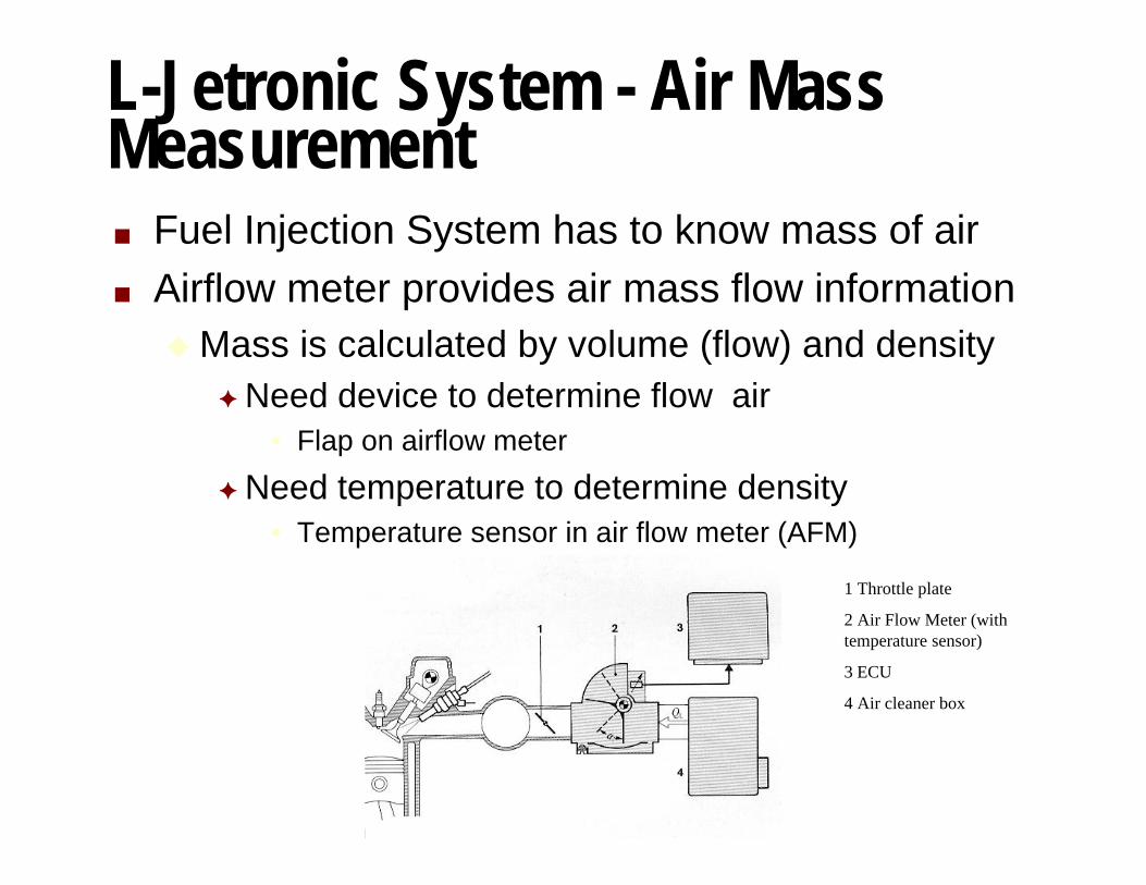
L-Jetronic System - Air MassMeasurementn Fuel Injection System has to know mass of airn Airflow meter provides air mass flow information
u Mass is calculated by volume (flow) and densityF Need device to determine flow air
• Flap on airflow meter
F Need temperature to determine density• Temperature sensor in air flow meter (AFM)
1 Throttle plate
2 Air Flow Meter (withtemperature sensor)
3 ECU
4 Air cleaner box

L-Jetronic System - Air FlowMeter - Mechanical Components
n AFM measures flow by spring loaded flap (door)n Greater flow forces flap open.n Compensation flap and damping chamber act like
shock absorber allowing door to settle quickly andto make it insensitive to vacuum pulsation’s fromcylinders
1 Compensation Valve
2 Damping Chamber
3 Air Bypass (idle mixture)
4 Air Sensor Flap
5 Idle mixture adjusting screw
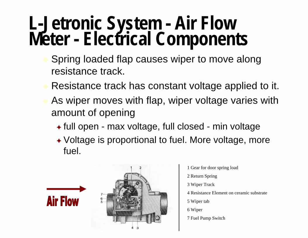
L-Jetronic System - Air FlowMeter - Electrical Components
u Spring loaded flap causes wiper to move alongresistance track.
u Resistance track has constant voltage applied to it.u As wiper moves with flap, wiper voltage varies with
amount of openingF full open - max voltage, full closed - min voltageF Voltage is proportional to fuel. More voltage, more
fuel.
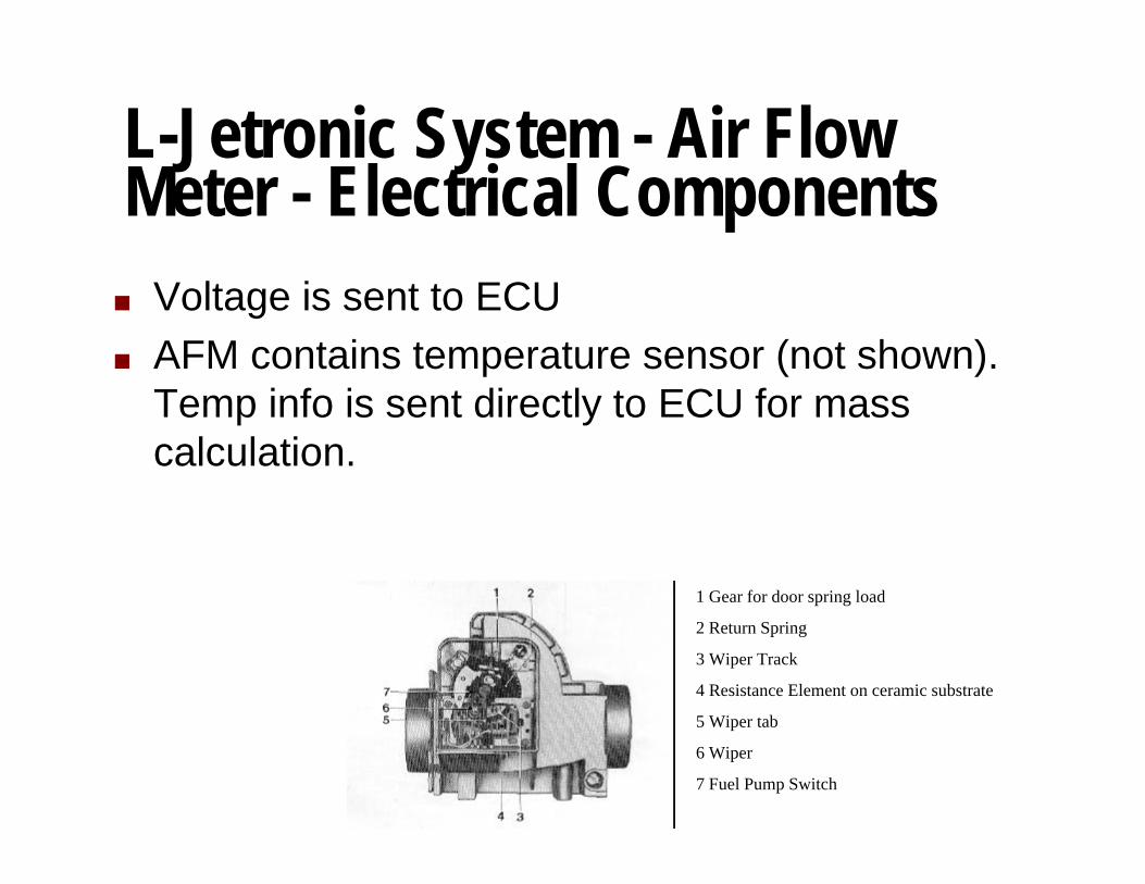
1 Gear for door spring load
2 Return Spring
3 Wiper Track
4 Resistance Element on ceramic substrate
5 Wiper tab
6 Wiper
7 Fuel Pump Switch
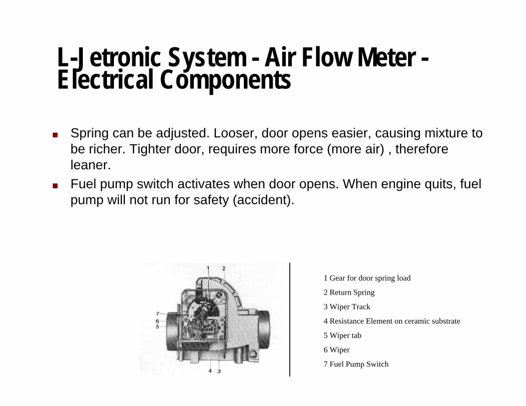
L-Jetronic System - Air Flow Meter -Electrical Components
n Spring can be adjusted. Looser, door opens easier, causing mixture tobe richer. Tighter door, requires more force (more air) , thereforeleaner.
n Fuel pump switch activates when door opens. When engine quits, fuelpump will not run for safety (accident).
1 Gear for door spring load
2 Return Spring
3 Wiper Track
4 Resistance Element on ceramic substrate
5 Wiper tab
6 Wiper
7 Fuel Pump Switch
L-Jetronic System - Air FlowMeter - Electrical Components
n Voltage is sent to ECUn AFM contains temperature sensor (not shown).
Temp info is sent directly to ECU for masscalculation.
1 Gear for door spring load
2 Return Spring
3 Wiper Track
4 Resistance Element on ceramic substrate
5 Wiper tab
6 Wiper
7 Fuel Pump Switch
L-Jetronic System - Air FlowMeter - Fuel Calculations
n The ECU uses mass measurement to meter fuelthrough injectors.
n When accelerating, the door will overshootslightly.u This overshoot causes extra fuel to be delivered
through injectorsu This serves as accelerator pump similar to
carburetors
L-Jetronic System - Air FlowMeter - Idle Mixture
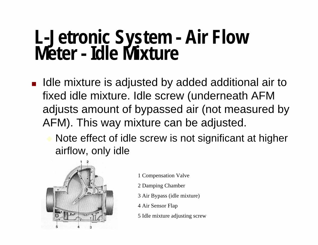
n Idle mixture is adjusted by added additional air tofixed idle mixture. Idle screw (underneath AFMadjusts amount of bypassed air (not measured byAFM). This way mixture can be adjusted.u Note effect of idle screw is not significant at higher
airflow, only idle
1 Compensation Valve
2 Damping Chamber
3 Air Bypass (idle mixture)
4 Air Sensor Flap
5 Idle mixture adjusting screw
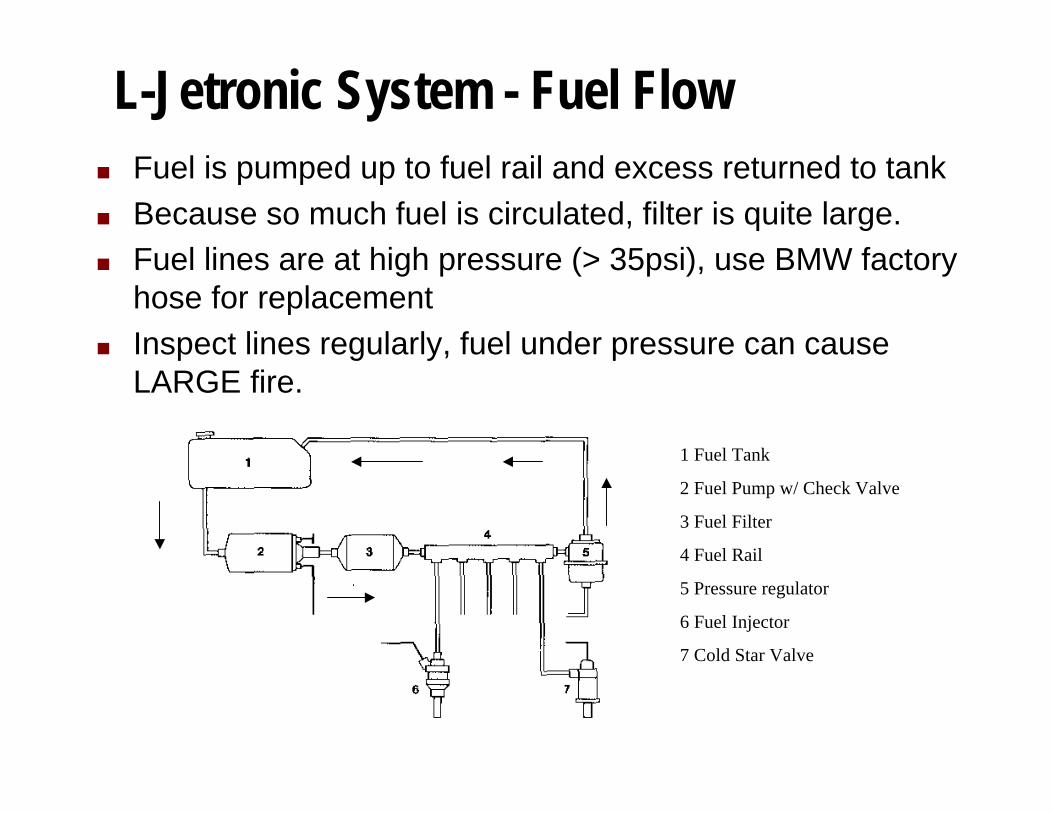
L-Jetronic System - Fuel Flown Fuel is pumped up to fuel rail and excess returned to tankn Because so much fuel is circulated, filter is quite large.n Fuel lines are at high pressure (> 35psi), use BMW factory
hose for replacementn Inspect lines regularly, fuel under pressure can cause
LARGE fire.
1 Fuel Tank
2 Fuel Pump w/ Check Valve
3 Fuel Filter
4 Fuel Rail
5 Pressure regulator
6 Fuel Injector
7 Cold Star Valve

L-Jetronic System - Fuel Pumpn Uses positive displacement roller pump.n Electric motor is in fuel stream and uses fuel to cool it.
u Because there is no air, it won’t explode.
n It’s important not to run low on fuel as the pump canoverheat and fail if fuel starved.
n Check fuel pump fuse (fuse #1, 16 amp) for corrosion -common no start or stall failure. I replace every 2 yearsand clean the fuse holder contacts.
1 Suction Side (inlet from tank)
2 Pressure relief valve
3 Roller pump mechanism
4 Motor
5 Check valve
6 Pump discharge (outlet tofilter)
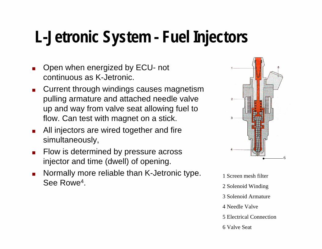
L-Jetronic System - Fuel Injectors
n Open when energized by ECU- notcontinuous as K-Jetronic.
n Current through windings causes magnetismpulling armature and attached needle valveup and way from valve seat allowing fuel toflow. Can test with magnet on a stick.
n All injectors are wired together and firesimultaneously,
n Flow is determined by pressure acrossinjector and time (dwell) of opening.
n Normally more reliable than K-Jetronic type.See Rowe4.
1 Screen mesh filter
2 Solenoid Winding
3 Solenoid Armature
4 Needle Valve
5 Electrical Connection
6 Valve Seat
6
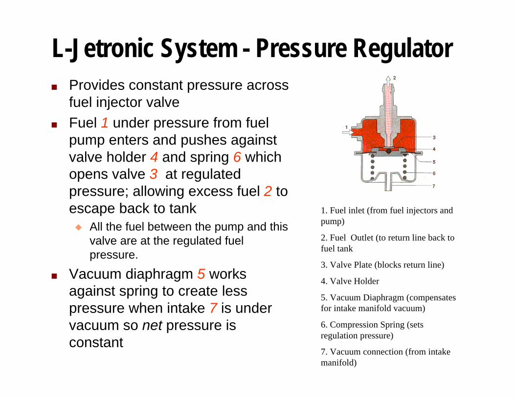
L-Jetronic System - Pressure Regulatorn Provides constant pressure across
fuel injector valven Fuel 1 under pressure from fuel
pump enters and pushes againstvalve holder 4 and spring 6 whichopens valve 3 at regulatedpressure; allowing excess fuel 2 toescape back to tank
u All the fuel between the pump and thisvalve are at the regulated fuelpressure.
n Vacuum diaphragm 5 worksagainst spring to create lesspressure when intake 7 is undervacuum so net pressure isconstant
1. Fuel inlet (from fuel injectors andpump)
2. Fuel Outlet (to return line back tofuel tank
3. Valve Plate (blocks return line)
4. Valve Holder
5. Vacuum Diaphragm (compensatesfor intake manifold vacuum)
6. Compression Spring (setsregulation pressure)
7. Vacuum connection (from intakemanifold)
L-Jetronic System - Control Unitn Control unit (ECU) takes sensor information:
u AFM flow and temperature
u Engine RPM (from ignition)u Warm up information (from coolant temperature sensor)
u Throttle mode (idle and WOT switches)
u O2 sensor in Lambda systems
n ….and calculates opening duration of injectorsn This ‘map’ is hardwired into system (there’s no chip
available to modify)n Some users have adjusted value of internal
components5.
L-Jetronic System - Control Unit -Throttle Operating Modes
n Idleu Throttle is closed
u Idle switch is closed, ECU supplies idle mixture (a little rich) forsmooth idle
n Off - idle
u Both switches are open. ECU reads AFM signal and O2 sensor(where installed) and determines how long to open injectors forproper mixture.
n Wide Open Throttle (WOT)or ‘Yeeeehaaaa! zone’
u WOT switch is closed
u Injector open time is fixed amount. Somewhat rich for addedpower.
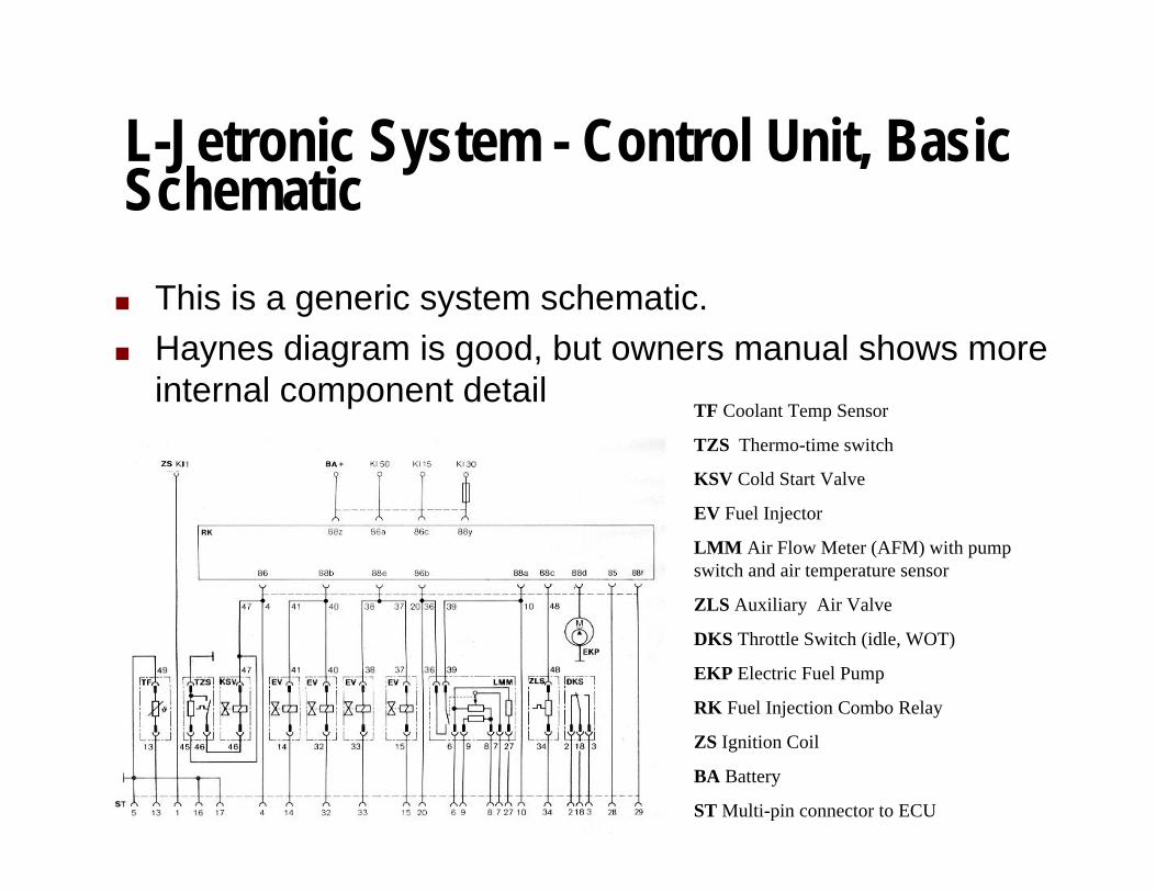
L-Jetronic System - Control Unit, BasicSchematic
n This is a generic system schematic.n Haynes diagram is good, but owners manual shows more
internal component detailTF Coolant Temp Sensor
TZS Thermo-time switch
KSV Cold Start Valve
EV Fuel Injector
LMM Air Flow Meter (AFM) with pumpswitch and air temperature sensor
ZLS Auxiliary Air Valve
DKS Throttle Switch (idle, WOT)
EKP Electric Fuel Pump
RK Fuel Injection Combo Relay
ZS Ignition Coil
BA Battery
ST Multi-pin connector to ECU

L-Jetronic System - Control Unit Pin out Seen into the female connectors.
+----------------------------------------------------+
| o o o o o o o o o o o o o o o o o |
+-----+ 35 34 33 32 31 30 29 28 27 26 25 24 23 22 21 20 19 +----+
| o o o o o o o o o o o o o o o o o o |
| 18 17 16 15 14 13 12 11 10 9 8 7 6 5 4 3 2 1 |
+---------------------------------------------------------------+
1. Ignition coil 19. No connection
2. Throttle switch, idle ? 20. Main relay + engine running
3. Throttle switch, WOT ? 21. No connection
4. Pin 50 via main relay 22. No connection
5. Earth connection 23. No connection
6. Air flow sensor + ? 24. No connection
7. Air flow sensor signal 25. No connection
8. Air flow sensor - ? 26: No connection
9. Air flow sensor air temp. 27. Air flow sensor
10. Main relay, pin 15 28. No connection
11. No connection 29. No connection
12. No connection 30. Injectors
13. Coolant temperature sensor 31. Injectors
14. Injectors 32. Injectors
15. Injectors 33. Injectors
16. Earth connection 34. Auxiliary air valve, bimetal
17. Earth connection 35. Earth connection
18. Throttle switch +
L-Jetronic System - Lambda - Why?
n Basic L-Jetronic System measures air mass andprovides appropriate amount of fuel
n Note: although a precision system, there is nofeedback for the system to know of any variances:u Aging components
u Fuel characteristic differences
n Catalytic converters require precise mixturecontrol for operation
n The air fuel ratio of standard L-Jetronic system isnot accurate enough for proper catalytic converteroperation
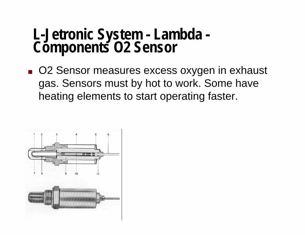
L-Jetronic System - Lambda -Components O2 Sensor
n O2 Sensor measures excess oxygen in exhaustgas. Sensors must by hot to work. Some haveheating elements to start operating faster.

L-Jetronic System - Lambda -Components O2 Sensor Output Curve
n The sensors output changes rapidly around the 14.7 to 1 ratio. Thisprovides a mixture with just enough oxygen to burn hydrocarbons incatalytic converter.
n The lambda system controls around this point. The ECU cyclesmixture lean and rich slightly. It looks at the average of the lambdasignal and adjusts the average of the mixture accordingly.
Excess Air Factor (Lambda)
Sensor Voltage
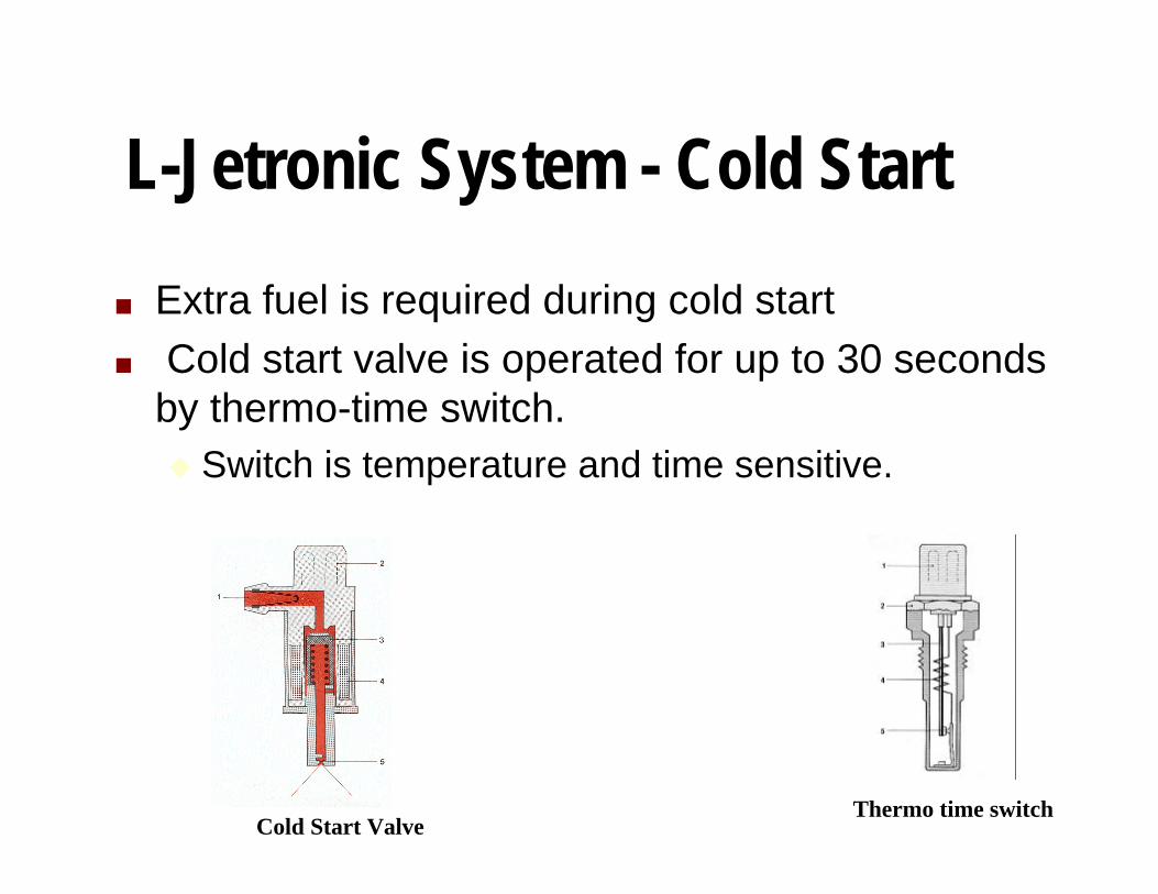
L-Jetronic System - Cold Start
n Extra fuel is required during cold startn Cold start valve is operated for up to 30 seconds
by thermo-time switch.u Switch is temperature and time sensitive.
Cold Start ValveThermo time switch
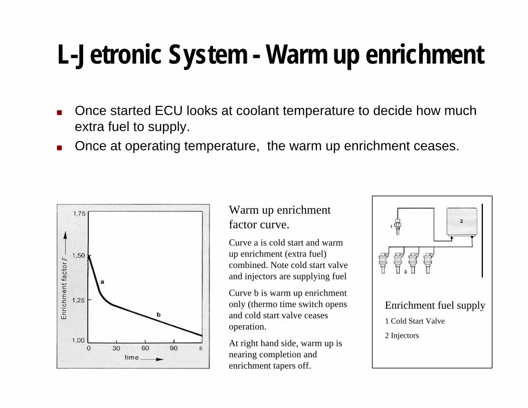
L-Jetronic System - Warm up enrichment
n Once started ECU looks at coolant temperature to decide how muchextra fuel to supply.
n Once at operating temperature, the warm up enrichment ceases.
Warm up enrichmentfactor curve.
Curve a is cold start and warmup enrichment (extra fuel)combined. Note cold start valveand injectors are supplying fuel
Curve b is warm up enrichmentonly (thermo time switch opensand cold start valve ceasesoperation.
At right hand side, warm up isnearing completion andenrichment tapers off.
Enrichment fuel supply1 Cold Start Valve
2 Injectors
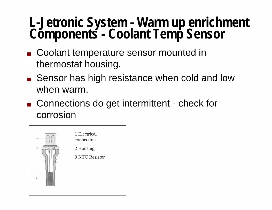
L-Jetronic System - Warm up enrichmentComponents - Coolant Temp Sensor
n Coolant temperature sensor mounted inthermostat housing.
n Sensor has high resistance when cold and lowwhen warm.
n Connections do get intermittent - check forcorrosion
1 Electricalconnection
2 Housing
3 NTC Resistor
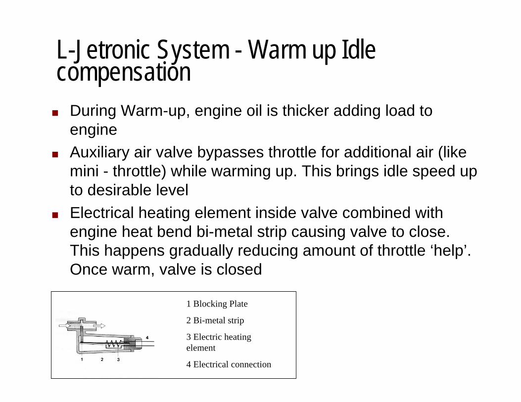
L-Jetronic System - Warm up Idlecompensation
n During Warm-up, engine oil is thicker adding load toengine
n Auxiliary air valve bypasses throttle for additional air (likemini - throttle) while warming up. This brings idle speed upto desirable level
n Electrical heating element inside valve combined withengine heat bend bi-metal strip causing valve to close.This happens gradually reducing amount of throttle ‘help’.Once warm, valve is closed
1 Blocking Plate
2 Bi-metal strip
3 Electric heatingelement
4 Electrical connection

Troubleshooting
Ask us questions!!

Conversion to Lambda ControlBy Scott Stewart - First Fives Registry
Greg’s note:
If you have a 528i, you don't have to worry about this, but if you have a 530i, keep reading.The following describes the process of converting your fuel injection system to the laterstyle Bosch L-Jetronic with lambda control.
The object here is to assemble a FI system that is properly tuned, provides gooddriveability, low fuel consumption, and has minimal emissions.
I had my 530i checked for emissions after I retrofitted my L-jet with Lambda control FIsystem from a 528i. It's emissions are lower without a catalytic converter than what theoriginal specs call for on a 1977 530i. The L-jet with lambda control FI system is leapyears ahead of the one on your car now because it actually monitors the fuel/air(stoichometric) ratio rather than assuming it is OK. My performance is up, driveability ismuch better (my car would flood at high rpm’s when it was cold before I changed to thenew system) better fuel consumption, and of course the lower emissions.
Following is a quick list of the components I assembled for the conversion. Any questions,additions, or comments are welcome from those that currently drive "the real thing" 528ior from others who have done this conversion (Marty Roach).

Conversion to Lambda Control - Continued; Parts ListAll parts were removed from a running 1981 528i:
l 122 extension ECU, same connection as the 106 original model in the 530i. Make sureyou plug in the single spade terminal at the ECU that is not part of the FI wiring harness.I think this plug is the distributor pickup or Pin #1 on the ECU (help here from those inthe know).
l Complete FI and engine wiring harness from the 528i
l 528i valve coverl 528i throttle body with 4 contact limit switches
l 528i AFMl auxiliary air valve and AC bypass valve off of 528il exhaust manifold down-pipe with threaded port for 02 sensor
l 528i combo relayl later style vacuum advance/retard distributor with transistorized ignition, ignition module,
resistor bank etc. Mount it on inside of uni-body behind the windshield washer bottlewith heatsink grease (resistor bank gets pretty hot). Don't forget the engine wiringharness coming from the ignition module to the distributor, ignition coil, temperaturesending unit, alternator (power and spade terminal for idiot light), and oil pressuresending unit. This harness will have a plug that plugs right into your fuse box.
l 528i thermostat housing with fittings for vacuum retard during cold running, temp timeswitch, temp sending unit for gauge and FI (this makes the FI wiring harness mucheasier to fit)
l 528i plenum chamberl 528i fuel rail, fuel pressure regulator, injectors.
Conversion to Lambda Control - Continued; summary
I am sure you are saying WHAT!! by now but believe me it is worth the hassle. I don't know ifthe exhaust manifold from a 528i is necessary, my car had headers on it so I never sawthe original 530i exhaust manifold.
OK. Thanks to Peter Florance I just happen to know the only mods that are necessary to thewiring in your car once the FI and engine wiring harness are in place are:
Remove the purple/green and yellow/green wires from the Fuel pump side plug in yourcombo relay (easily done with a knife that will flatten the tab that holds the terminal in theplug). Remove these same two wires from the Fuel pump side plug of the combo relaythat came on the new 528i wiring harness and replace these wires with the two out ofyour harness. Tie wrap everything down and tape up the old combo relay plug withelectrical tape (the main power, red, wire still has power to it)and start the car.
I hope some of this helps you or anyone else brave enough to perform the upgrade.
Scott Stewart
Peter’s note: We are trying to see if this can be done w/out the harness swap.
Bibliography and SuggestedReading
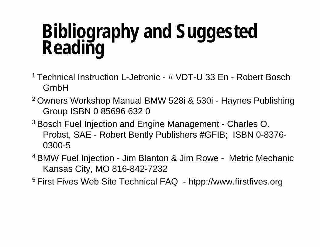
1 Technical Instruction L-Jetronic - # VDT-U 33 En - Robert BoschGmbH
2 Owners Workshop Manual BMW 528i & 530i - Haynes PublishingGroup ISBN 0 85696 632 0
3 Bosch Fuel Injection and Engine Management - Charles O.Probst, SAE - Robert Bently Publishers #GFIB; ISBN 0-8376-0300-5
4 BMW Fuel Injection - Jim Blanton & Jim Rowe - Metric MechanicKansas City, MO 816-842-7232
5 First Fives Web Site Technical FAQ - htpp://www.firstfives.org