L E L E DCRG8F - Lovato Electric
50
I564 GB I 05 20 1 LOVATO ELECTRIC S.P.A. 24020 GORLE (BERGAMO) ITALIA VIA DON E. MAZZA, 12 TEL. 035 4282111 E-mail info@LovatoElectric.com Web www.LovatoElectric.com DCRG8F AUTOMATIC POWER FACTOR CONTROLLER Instructions manual GB WARNING! – Carefully read the manual before the installation or use. – This equipment is to be installed by qualified personnel, complying to current standards, to avoid damages or safety hazards. – Before any service work on the device, remove all the voltages from measuring and supply inputs and short-circuit the CT input terminals. – The manufacturer cannot be held responsible for electrical safety in case of improper use of the equipment. – Products illustrated herein are subject to alteration and changes without prior notice. Technical data and descriptions in the documentation are accurate, to the best of our knowledge, but no liabilities for errors, omissions or contingencies arising there from are accepted. – A circuit breaker must be included in the electrical installation of the building. It must be installed close by the equipment and within easy reach of the operator. It must be marked as the disconnecting device of the equipment: IEC /EN 61010-1 § 6.11.3.1. – Clean the device with a soft dry cloth; do not use abrasive products, liquid detergents or solvents. INDEX Page Introduction . . . . . . . . . . . . . . . . . . . . . . . . . . . . . . . . . . . . . . . . . . . . . . . . . . . . . . . . . . . . . . . . . . . . . . . . . . . . . . . . . . . . . . . . . . . . . . . . . . . . . . . . . . . . . . . . . . . . . . . . . . . . . . . . . . . . . . . . . . . . . . . . . . . . . . . . . . . . . 2 Description . . . . . . . . . . . . . . . . . . . . . . . . . . . . . . . . . . . . . . . . . . . . . . . . . . . . . . . . . . . . . . . . . . . . . . . . . . . . . . . . . . . . . . . . . . . . . . . . . . . . . . . . . . . . . . . . . . . . . . . . . . . . . . . . . . . . . . . . . . . . . . . . . . . . . . . . . . . . . 2 Keyboard functions . . . . . . . . . . . . . . . . . . . . . . . . . . . . . . . . . . . . . . . . . . . . . . . . . . . . . . . . . . . . . . . . . . . . . . . . . . . . . . . . . . . . . . . . . . . . . . . . . . . . . . . . . . . . . . . . . . . . . . . . . . . . . . . . . . . . . . . . . . . . . . . . . . . . . . . 2 Front LED indication . . . . . . . . . . . . . . . . . . . . . . . . . . . . . . . . . . . . . . . . . . . . . . . . . . . . . . . . . . . . . . . . . . . . . . . . . . . . . . . . . . . . . . . . . . . . . . . . . . . . . . . . . . . . . . . . . . . . . . . . . . . . . . . . . . . . . . . . . . . . . . . . . . . . . . 2 First power-up . . . . . . . . . . . . . . . . . . . . . . . . . . . . . . . . . . . . . . . . . . . . . . . . . . . . . . . . . . . . . . . . . . . . . . . . . . . . . . . . . . . . . . . . . . . . . . . . . . . . . . . . . . . . . . . . . . . . . . . . . . . . . . . . . . . . . . . . . . . . . . . . . . . . . . . . . . . 2 Operating modes . . . . . . . . . . . . . . . . . . . . . . . . . . . . . . . . . . . . . . . . . . . . . . . . . . . . . . . . . . . . . . . . . . . . . . . . . . . . . . . . . . . . . . . . . . . . . . . . . . . . . . . . . . . . . . . . . . . . . . . . . . . . . . . . . . . . . . . . . . . . . . . . . . . . . . . . . 3 Main menu . . . . . . . . . . . . . . . . . . . . . . . . . . . . . . . . . . . . . . . . . . . . . . . . . . . . . . . . . . . . . . . . . . . . . . . . . . . . . . . . . . . . . . . . . . . . . . . . . . . . . . . . . . . . . . . . . . . . . . . . . . . . . . . . . . . . . . . . . . . . . . . . . . . . . . . . . . . . . 3 Password access . . . . . . . . . . . . . . . . . . . . . . . . . . . . . . . . . . . . . . . . . . . . . . . . . . . . . . . . . . . . . . . . . . . . . . . . . . . . . . . . . . . . . . . . . . . . . . . . . . . . . . . . . . . . . . . . . . . . . . . . . . . . . . . . . . . . . . . . . . . . . . . . . . . . . . . . . 3 Display page navigation . . . . . . . . . . . . . . . . . . . . . . . . . . . . . . . . . . . . . . . . . . . . . . . . . . . . . . . . . . . . . . . . . . . . . . . . . . . . . . . . . . . . . . . . . . . . . . . . . . . . . . . . . . . . . . . . . . . . . . . . . . . . . . . . . . . . . . . . . . . . . . . . . . . . 4 Table of display pages . . . . . . . . . . . . . . . . . . . . . . . . . . . . . . . . . . . . . . . . . . . . . . . . . . . . . . . . . . . . . . . . . . . . . . . . . . . . . . . . . . . . . . . . . . . . . . . . . . . . . . . . . . . . . . . . . . . . . . . . . . . . . . . . . . . . . . . . . . . . . . . . . . . . . 4 Harmonic analysis page . . . . . . . . . . . . . . . . . . . . . . . . . . . . . . . . . . . . . . . . . . . . . . . . . . . . . . . . . . . . . . . . . . . . . . . . . . . . . . . . . . . . . . . . . . . . . . . . . . . . . . . . . . . . . . . . . . . . . . . . . . . . . . . . . . . . . . . . . . . . . . . . . . . 5 Waveform page . . . . . . . . . . . . . . . . . . . . . . . . . . . . . . . . . . . . . . . . . . . . . . . . . . . . . . . . . . . . . . . . . . . . . . . . . . . . . . . . . . . . . . . . . . . . . . . . . . . . . . . . . . . . . . . . . . . . . . . . . . . . . . . . . . . . . . . . . . . . . . . . . . . . . . . . . . 6 Expandability . . . . . . . . . . . . . . . . . . . . . . . . . . . . . . . . . . . . . . . . . . . . . . . . . . . . . . . . . . . . . . . . . . . . . . . . . . . . . . . . . . . . . . . . . . . . . . . . . . . . . . . . . . . . . . . . . . . . . . . . . . . . . . . . . . . . . . . . . . . . . . . . . . . . . . . . . . . . 6 Additional resources . . . . . . . . . . . . . . . . . . . . . . . . . . . . . . . . . . . . . . . . . . . . . . . . . . . . . . . . . . . . . . . . . . . . . . . . . . . . . . . . . . . . . . . . . . . . . . . . . . . . . . . . . . . . . . . . . . . . . . . . . . . . . . . . . . . . . . . . . . . . . . . . . . . . . . 7 Communication channels . . . . . . . . . . . . . . . . . . . . . . . . . . . . . . . . . . . . . . . . . . . . . . . . . . . . . . . . . . . . . . . . . . . . . . . . . . . . . . . . . . . . . . . . . . . . . . . . . . . . . . . . . . . . . . . . . . . . . . . . . . . . . . . . . . . . . . . . . . . . . . . . . . 7 Modem GSM - GPRS . . . . . . . . . . . . . . . . . . . . . . . . . . . . . . . . . . . . . . . . . . . . . . . . . . . . . . . . . . . . . . . . . . . . . . . . . . . . . . . . . . . . . . . . . . . . . . . . . . . . . . . . . . . . . . . . . . . . . . . . . . . . . . . . . . . . . . . . . . . . . . . . . . . . . 7 Inputs, outputs, internal variables, counters, analog inputs . . . . . . . . . . . . . . . . . . . . . . . . . . . . . . . . . . . . . . . . . . . . . . . . . . . . . . . . . . . . . . . . . . . . . . . . . . . . . . . . . . . . . . . . . . . . . . . . . . . . . . . . . . . . . . . . . . . . . . . . 8 Limit thresholds . . . . . . . . . . . . . . . . . . . . . . . . . . . . . . . . . . . . . . . . . . . . . . . . . . . . . . . . . . . . . . . . . . . . . . . . . . . . . . . . . . . . . . . . . . . . . . . . . . . . . . . . . . . . . . . . . . . . . . . . . . . . . . . . . . . . . . . . . . . . . . . . . . . . . . . . . 8 Remote-controlled variables . . . . . . . . . . . . . . . . . . . . . . . . . . . . . . . . . . . . . . . . . . . . . . . . . . . . . . . . . . . . . . . . . . . . . . . . . . . . . . . . . . . . . . . . . . . . . . . . . . . . . . . . . . . . . . . . . . . . . . . . . . . . . . . . . . . . . . . . . . . . . . . . 9 User alarms . . . . . . . . . . . . . . . . . . . . . . . . . . . . . . . . . . . . . . . . . . . . . . . . . . . . . . . . . . . . . . . . . . . . . . . . . . . . . . . . . . . . . . . . . . . . . . . . . . . . . . . . . . . . . . . . . . . . . . . . . . . . . . . . . . . . . . . . . . . . . . . . . . . . . . . . . . . . . 9 Command of DCTL thyristor modules via RS485 bus . . . . . . . . . . . . . . . . . . . . . . . . . . . . . . . . . . . . . . . . . . . . . . . . . . . . . . . . . . . . . . . . . . . . . . . . . . . . . . . . . . . . . . . . . . . . . . . . . . . . . . . . . . . . . . . . . . . . . . . . . . . . . 9 IR programming port . . . . . . . . . . . . . . . . . . . . . . . . . . . . . . . . . . . . . . . . . . . . . . . . . . . . . . . . . . . . . . . . . . . . . . . . . . . . . . . . . . . . . . . . . . . . . . . . . . . . . . . . . . . . . . . . . . . . . . . . . . . . . . . . . . . . . . . . . . . . . . . . . . . . . 10 Parameter setting through PC . . . . . . . . . . . . . . . . . . . . . . . . . . . . . . . . . . . . . . . . . . . . . . . . . . . . . . . . . . . . . . . . . . . . . . . . . . . . . . . . . . . . . . . . . . . . . . . . . . . . . . . . . . . . . . . . . . . . . . . . . . . . . . . . . . . . . . . . . . . . . . . 10 Parameter setting (setup) from front panel . . . . . . . . . . . . . . . . . . . . . . . . . . . . . . . . . . . . . . . . . . . . . . . . . . . . . . . . . . . . . . . . . . . . . . . . . . . . . . . . . . . . . . . . . . . . . . . . . . . . . . . . . . . . . . . . . . . . . . . . . . . . . . . . . . . . . 10 Parameter tables . . . . . . . . . . . . . . . . . . . . . . . . . . . . . . . . . . . . . . . . . . . . . . . . . . . . . . . . . . . . . . . . . . . . . . . . . . . . . . . . . . . . . . . . . . . . . . . . . . . . . . . . . . . . . . . . . . . . . . . . . . . . . . . . . . . . . . . . . . . . . . . . . . . . . . . . . 11 Output functions table . . . . . . . . . . . . . . . . . . . . . . . . . . . . . . . . . . . . . . . . . . . . . . . . . . . . . . . . . . . . . . . . . . . . . . . . . . . . . . . . . . . . . . . . . . . . . . . . . . . . . . . . . . . . . . . . . . . . . . . . . . . . . . . . . . . . . . . . . . . . . . . . . . . . . 14 Input functions table . . . . . . . . . . . . . . . . . . . . . . . . . . . . . . . . . . . . . . . . . . . . . . . . . . . . . . . . . . . . . . . . . . . . . . . . . . . . . . . . . . . . . . . . . . . . . . . . . . . . . . . . . . . . . . . . . . . . . . . . . . . . . . . . . . . . . . . . . . . . . . . . . . . . . . 14 Alarms . . . . . . . . . . . . . . . . . . . . . . . . . . . . . . . . . . . . . . . . . . . . . . . . . . . . . . . . . . . . . . . . . . . . . . . . . . . . . . . . . . . . . . . . . . . . . . . . . . . . . . . . . . . . . . . . . . . . . . . . . . . . . . . . . . . . . . . . . . . . . . . . . . . . . . . . . . . . . . . . . 19 Alarm description . . . . . . . . . . . . . . . . . . . . . . . . . . . . . . . . . . . . . . . . . . . . . . . . . . . . . . . . . . . . . . . . . . . . . . . . . . . . . . . . . . . . . . . . . . . . . . . . . . . . . . . . . . . . . . . . . . . . . . . . . . . . . . . . . . . . . . . . . . . . . . . . . . . . . . . . 19 Alarm properties . . . . . . . . . . . . . . . . . . . . . . . . . . . . . . . . . . . . . . . . . . . . . . . . . . . . . . . . . . . . . . . . . . . . . . . . . . . . . . . . . . . . . . . . . . . . . . . . . . . . . . . . . . . . . . . . . . . . . . . . . . . . . . . . . . . . . . . . . . . . . . . . . . . . . . . . . 19 Alarm property table . . . . . . . . . . . . . . . . . . . . . . . . . . . . . . . . . . . . . . . . . . . . . . . . . . . . . . . . . . . . . . . . . . . . . . . . . . . . . . . . . . . . . . . . . . . . . . . . . . . . . . . . . . . . . . . . . . . . . . . . . . . . . . . . . . . . . . . . . . . . . . . . . . . . . . 20 Commands menu . . . . . . . . . . . . . . . . . . . . . . . . . . . . . . . . . . . . . . . . . . . . . . . . . . . . . . . . . . . . . . . . . . . . . . . . . . . . . . . . . . . . . . . . . . . . . . . . . . . . . . . . . . . . . . . . . . . . . . . . . . . . . . . . . . . . . . . . . . . . . . . . . . . . . . . . 20 Measurement table for limit thresholds and analog outputs . . . . . . . . . . . . . . . . . . . . . . . . . . . . . . . . . . . . . . . . . . . . . . . . . . . . . . . . . . . . . . . . . . . . . . . . . . . . . . . . . . . . . . . . . . . . . . . . . . . . . . . . . . . . . . . . . . . . . . . . 21 Wiring diagrams . . . . . . . . . . . . . . . . . . . . . . . . . . . . . . . . . . . . . . . . . . . . . . . . . . . . . . . . . . . . . . . . . . . . . . . . . . . . . . . . . . . . . . . . . . . . . . . . . . . . . . . . . . . . . . . . . . . . . . . . . . . . . . . . . . . . . . . . . . . . . . . . . . . . . . . . . 23 Terminal arrangement . . . . . . . . . . . . . . . . . . . . . . . . . . . . . . . . . . . . . . . . . . . . . . . . . . . . . . . . . . . . . . . . . . . . . . . . . . . . . . . . . . . . . . . . . . . . . . . . . . . . . . . . . . . . . . . . . . . . . . . . . . . . . . . . . . . . . . . . . . . . . . . . . . . . . 24 Installation . . . . . . . . . . . . . . . . . . . . . . . . . . . . . . . . . . . . . . . . . . . . . . . . . . . . . . . . . . . . . . . . . . . . . . . . . . . . . . . . . . . . . . . . . . . . . . . . . . . . . . . . . . . . . . . . . . . . . . . . . . . . . . . . . . . . . . . . . . . . . . . . . . . . . . . . . . . . . . 24 Mechanical dimensions and panel cutout . . . . . . . . . . . . . . . . . . . . . . . . . . . . . . . . . . . . . . . . . . . . . . . . . . . . . . . . . . . . . . . . . . . . . . . . . . . . . . . . . . . . . . . . . . . . . . . . . . . . . . . . . . . . . . . . . . . . . . . . . . . . . . . . . . . . . . 24 Technical carachteristics . . . . . . . . . . . . . . . . . . . . . . . . . . . . . . . . . . . . . . . . . . . . . . . . . . . . . . . . . . . . . . . . . . . . . . . . . . . . . . . . . . . . . . . . . . . . . . . . . . . . . . . . . . . . . . . . . . . . . . . . . . . . . . . . . . . . . . . . . . . . . . . . . . . 25 G B
Transcript of L E L E DCRG8F - Lovato Electric

I564 GB I 0
5 20
1
LOVATO ELECTRIC S.P.A.
24020 GORLE (BERGAMO) ITALIAVIA DON E. MAZZA, 12TEL. 035 4282111 E-mail [email protected] www.LovatoElectric.com
DCRG8F
AUTOMATIC POWER FACTOR CONTROLLER
Instructions manual
GB
WARNING! – Carefully read the manual before the installation or use.– This equipment is to be installed by qualified personnel, complying to current standards, to avoid damages or safety hazards. – Before any service work on the device, remove all the voltages from measuring and supply inputs and short-circuit the CT input terminals.– The manufacturer cannot be held responsible for electrical safety in case of improper use of the equipment. – Products illustrated herein are subject to alteration and changes without prior notice. Technical data and descriptions in the documentation are accurate, to the best of our knowledge, but no liabilities for errors,
omissions or contingencies arising there from are accepted.– A circuit breaker must be included in the electrical installation of the building. It must be installed close by the equipment and within easy reach of the operator. It must be marked as the disconnecting device of the
equipment: IEC /EN 61010-1 § 6.11.3.1.– Clean the device with a soft dry cloth; do not use abrasive products, liquid detergents or solvents.
INDEX PageIntroduction . . . . . . . . . . . . . . . . . . . . . . . . . . . . . . . . . . . . . . . . . . . . . . . . . . . . . . . . . . . . . . . . . . . . . . . . . . . . . . . . . . . . . . . . . . . . . . . . . . . . . . . . . . . . . . . . . . . . . . . . . . . . . . . . . . . . . . . . . . . . . . . . . . . . . . . . . . . . . 2Description . . . . . . . . . . . . . . . . . . . . . . . . . . . . . . . . . . . . . . . . . . . . . . . . . . . . . . . . . . . . . . . . . . . . . . . . . . . . . . . . . . . . . . . . . . . . . . . . . . . . . . . . . . . . . . . . . . . . . . . . . . . . . . . . . . . . . . . . . . . . . . . . . . . . . . . . . . . . . 2Keyboard functions . . . . . . . . . . . . . . . . . . . . . . . . . . . . . . . . . . . . . . . . . . . . . . . . . . . . . . . . . . . . . . . . . . . . . . . . . . . . . . . . . . . . . . . . . . . . . . . . . . . . . . . . . . . . . . . . . . . . . . . . . . . . . . . . . . . . . . . . . . . . . . . . . . . . . . . 2Front LED indication . . . . . . . . . . . . . . . . . . . . . . . . . . . . . . . . . . . . . . . . . . . . . . . . . . . . . . . . . . . . . . . . . . . . . . . . . . . . . . . . . . . . . . . . . . . . . . . . . . . . . . . . . . . . . . . . . . . . . . . . . . . . . . . . . . . . . . . . . . . . . . . . . . . . . . 2First power-up . . . . . . . . . . . . . . . . . . . . . . . . . . . . . . . . . . . . . . . . . . . . . . . . . . . . . . . . . . . . . . . . . . . . . . . . . . . . . . . . . . . . . . . . . . . . . . . . . . . . . . . . . . . . . . . . . . . . . . . . . . . . . . . . . . . . . . . . . . . . . . . . . . . . . . . . . . . 2Operating modes . . . . . . . . . . . . . . . . . . . . . . . . . . . . . . . . . . . . . . . . . . . . . . . . . . . . . . . . . . . . . . . . . . . . . . . . . . . . . . . . . . . . . . . . . . . . . . . . . . . . . . . . . . . . . . . . . . . . . . . . . . . . . . . . . . . . . . . . . . . . . . . . . . . . . . . . . 3Main menu . . . . . . . . . . . . . . . . . . . . . . . . . . . . . . . . . . . . . . . . . . . . . . . . . . . . . . . . . . . . . . . . . . . . . . . . . . . . . . . . . . . . . . . . . . . . . . . . . . . . . . . . . . . . . . . . . . . . . . . . . . . . . . . . . . . . . . . . . . . . . . . . . . . . . . . . . . . . . 3Password access . . . . . . . . . . . . . . . . . . . . . . . . . . . . . . . . . . . . . . . . . . . . . . . . . . . . . . . . . . . . . . . . . . . . . . . . . . . . . . . . . . . . . . . . . . . . . . . . . . . . . . . . . . . . . . . . . . . . . . . . . . . . . . . . . . . . . . . . . . . . . . . . . . . . . . . . . 3Display page navigation . . . . . . . . . . . . . . . . . . . . . . . . . . . . . . . . . . . . . . . . . . . . . . . . . . . . . . . . . . . . . . . . . . . . . . . . . . . . . . . . . . . . . . . . . . . . . . . . . . . . . . . . . . . . . . . . . . . . . . . . . . . . . . . . . . . . . . . . . . . . . . . . . . . . 4Table of display pages . . . . . . . . . . . . . . . . . . . . . . . . . . . . . . . . . . . . . . . . . . . . . . . . . . . . . . . . . . . . . . . . . . . . . . . . . . . . . . . . . . . . . . . . . . . . . . . . . . . . . . . . . . . . . . . . . . . . . . . . . . . . . . . . . . . . . . . . . . . . . . . . . . . . . 4Harmonic analysis page . . . . . . . . . . . . . . . . . . . . . . . . . . . . . . . . . . . . . . . . . . . . . . . . . . . . . . . . . . . . . . . . . . . . . . . . . . . . . . . . . . . . . . . . . . . . . . . . . . . . . . . . . . . . . . . . . . . . . . . . . . . . . . . . . . . . . . . . . . . . . . . . . . . 5Waveform page . . . . . . . . . . . . . . . . . . . . . . . . . . . . . . . . . . . . . . . . . . . . . . . . . . . . . . . . . . . . . . . . . . . . . . . . . . . . . . . . . . . . . . . . . . . . . . . . . . . . . . . . . . . . . . . . . . . . . . . . . . . . . . . . . . . . . . . . . . . . . . . . . . . . . . . . . . 6Expandability . . . . . . . . . . . . . . . . . . . . . . . . . . . . . . . . . . . . . . . . . . . . . . . . . . . . . . . . . . . . . . . . . . . . . . . . . . . . . . . . . . . . . . . . . . . . . . . . . . . . . . . . . . . . . . . . . . . . . . . . . . . . . . . . . . . . . . . . . . . . . . . . . . . . . . . . . . . . 6Additional resources . . . . . . . . . . . . . . . . . . . . . . . . . . . . . . . . . . . . . . . . . . . . . . . . . . . . . . . . . . . . . . . . . . . . . . . . . . . . . . . . . . . . . . . . . . . . . . . . . . . . . . . . . . . . . . . . . . . . . . . . . . . . . . . . . . . . . . . . . . . . . . . . . . . . . . 7Communication channels . . . . . . . . . . . . . . . . . . . . . . . . . . . . . . . . . . . . . . . . . . . . . . . . . . . . . . . . . . . . . . . . . . . . . . . . . . . . . . . . . . . . . . . . . . . . . . . . . . . . . . . . . . . . . . . . . . . . . . . . . . . . . . . . . . . . . . . . . . . . . . . . . . 7Modem GSM - GPRS . . . . . . . . . . . . . . . . . . . . . . . . . . . . . . . . . . . . . . . . . . . . . . . . . . . . . . . . . . . . . . . . . . . . . . . . . . . . . . . . . . . . . . . . . . . . . . . . . . . . . . . . . . . . . . . . . . . . . . . . . . . . . . . . . . . . . . . . . . . . . . . . . . . . . 7Inputs, outputs, internal variables, counters, analog inputs . . . . . . . . . . . . . . . . . . . . . . . . . . . . . . . . . . . . . . . . . . . . . . . . . . . . . . . . . . . . . . . . . . . . . . . . . . . . . . . . . . . . . . . . . . . . . . . . . . . . . . . . . . . . . . . . . . . . . . . . 8Limit thresholds . . . . . . . . . . . . . . . . . . . . . . . . . . . . . . . . . . . . . . . . . . . . . . . . . . . . . . . . . . . . . . . . . . . . . . . . . . . . . . . . . . . . . . . . . . . . . . . . . . . . . . . . . . . . . . . . . . . . . . . . . . . . . . . . . . . . . . . . . . . . . . . . . . . . . . . . . 8Remote-controlled variables . . . . . . . . . . . . . . . . . . . . . . . . . . . . . . . . . . . . . . . . . . . . . . . . . . . . . . . . . . . . . . . . . . . . . . . . . . . . . . . . . . . . . . . . . . . . . . . . . . . . . . . . . . . . . . . . . . . . . . . . . . . . . . . . . . . . . . . . . . . . . . . . 9User alarms . . . . . . . . . . . . . . . . . . . . . . . . . . . . . . . . . . . . . . . . . . . . . . . . . . . . . . . . . . . . . . . . . . . . . . . . . . . . . . . . . . . . . . . . . . . . . . . . . . . . . . . . . . . . . . . . . . . . . . . . . . . . . . . . . . . . . . . . . . . . . . . . . . . . . . . . . . . . . 9Command of DCTL thyristor modules via RS485 bus . . . . . . . . . . . . . . . . . . . . . . . . . . . . . . . . . . . . . . . . . . . . . . . . . . . . . . . . . . . . . . . . . . . . . . . . . . . . . . . . . . . . . . . . . . . . . . . . . . . . . . . . . . . . . . . . . . . . . . . . . . . . . 9IR programming port . . . . . . . . . . . . . . . . . . . . . . . . . . . . . . . . . . . . . . . . . . . . . . . . . . . . . . . . . . . . . . . . . . . . . . . . . . . . . . . . . . . . . . . . . . . . . . . . . . . . . . . . . . . . . . . . . . . . . . . . . . . . . . . . . . . . . . . . . . . . . . . . . . . . . 10Parameter setting through PC . . . . . . . . . . . . . . . . . . . . . . . . . . . . . . . . . . . . . . . . . . . . . . . . . . . . . . . . . . . . . . . . . . . . . . . . . . . . . . . . . . . . . . . . . . . . . . . . . . . . . . . . . . . . . . . . . . . . . . . . . . . . . . . . . . . . . . . . . . . . . . . 10Parameter setting (setup) from front panel . . . . . . . . . . . . . . . . . . . . . . . . . . . . . . . . . . . . . . . . . . . . . . . . . . . . . . . . . . . . . . . . . . . . . . . . . . . . . . . . . . . . . . . . . . . . . . . . . . . . . . . . . . . . . . . . . . . . . . . . . . . . . . . . . . . . . 10Parameter tables . . . . . . . . . . . . . . . . . . . . . . . . . . . . . . . . . . . . . . . . . . . . . . . . . . . . . . . . . . . . . . . . . . . . . . . . . . . . . . . . . . . . . . . . . . . . . . . . . . . . . . . . . . . . . . . . . . . . . . . . . . . . . . . . . . . . . . . . . . . . . . . . . . . . . . . . . 11Output functions table . . . . . . . . . . . . . . . . . . . . . . . . . . . . . . . . . . . . . . . . . . . . . . . . . . . . . . . . . . . . . . . . . . . . . . . . . . . . . . . . . . . . . . . . . . . . . . . . . . . . . . . . . . . . . . . . . . . . . . . . . . . . . . . . . . . . . . . . . . . . . . . . . . . . . 14Input functions table . . . . . . . . . . . . . . . . . . . . . . . . . . . . . . . . . . . . . . . . . . . . . . . . . . . . . . . . . . . . . . . . . . . . . . . . . . . . . . . . . . . . . . . . . . . . . . . . . . . . . . . . . . . . . . . . . . . . . . . . . . . . . . . . . . . . . . . . . . . . . . . . . . . . . . 14Alarms . . . . . . . . . . . . . . . . . . . . . . . . . . . . . . . . . . . . . . . . . . . . . . . . . . . . . . . . . . . . . . . . . . . . . . . . . . . . . . . . . . . . . . . . . . . . . . . . . . . . . . . . . . . . . . . . . . . . . . . . . . . . . . . . . . . . . . . . . . . . . . . . . . . . . . . . . . . . . . . . . 19Alarm description . . . . . . . . . . . . . . . . . . . . . . . . . . . . . . . . . . . . . . . . . . . . . . . . . . . . . . . . . . . . . . . . . . . . . . . . . . . . . . . . . . . . . . . . . . . . . . . . . . . . . . . . . . . . . . . . . . . . . . . . . . . . . . . . . . . . . . . . . . . . . . . . . . . . . . . . 19Alarm properties . . . . . . . . . . . . . . . . . . . . . . . . . . . . . . . . . . . . . . . . . . . . . . . . . . . . . . . . . . . . . . . . . . . . . . . . . . . . . . . . . . . . . . . . . . . . . . . . . . . . . . . . . . . . . . . . . . . . . . . . . . . . . . . . . . . . . . . . . . . . . . . . . . . . . . . . . 19Alarm property table . . . . . . . . . . . . . . . . . . . . . . . . . . . . . . . . . . . . . . . . . . . . . . . . . . . . . . . . . . . . . . . . . . . . . . . . . . . . . . . . . . . . . . . . . . . . . . . . . . . . . . . . . . . . . . . . . . . . . . . . . . . . . . . . . . . . . . . . . . . . . . . . . . . . . . 20Commands menu . . . . . . . . . . . . . . . . . . . . . . . . . . . . . . . . . . . . . . . . . . . . . . . . . . . . . . . . . . . . . . . . . . . . . . . . . . . . . . . . . . . . . . . . . . . . . . . . . . . . . . . . . . . . . . . . . . . . . . . . . . . . . . . . . . . . . . . . . . . . . . . . . . . . . . . . 20Measurement table for limit thresholds and analog outputs . . . . . . . . . . . . . . . . . . . . . . . . . . . . . . . . . . . . . . . . . . . . . . . . . . . . . . . . . . . . . . . . . . . . . . . . . . . . . . . . . . . . . . . . . . . . . . . . . . . . . . . . . . . . . . . . . . . . . . . . 21Wiring diagrams . . . . . . . . . . . . . . . . . . . . . . . . . . . . . . . . . . . . . . . . . . . . . . . . . . . . . . . . . . . . . . . . . . . . . . . . . . . . . . . . . . . . . . . . . . . . . . . . . . . . . . . . . . . . . . . . . . . . . . . . . . . . . . . . . . . . . . . . . . . . . . . . . . . . . . . . . 23Terminal arrangement . . . . . . . . . . . . . . . . . . . . . . . . . . . . . . . . . . . . . . . . . . . . . . . . . . . . . . . . . . . . . . . . . . . . . . . . . . . . . . . . . . . . . . . . . . . . . . . . . . . . . . . . . . . . . . . . . . . . . . . . . . . . . . . . . . . . . . . . . . . . . . . . . . . . . 24Installation . . . . . . . . . . . . . . . . . . . . . . . . . . . . . . . . . . . . . . . . . . . . . . . . . . . . . . . . . . . . . . . . . . . . . . . . . . . . . . . . . . . . . . . . . . . . . . . . . . . . . . . . . . . . . . . . . . . . . . . . . . . . . . . . . . . . . . . . . . . . . . . . . . . . . . . . . . . . . . 24Mechanical dimensions and panel cutout . . . . . . . . . . . . . . . . . . . . . . . . . . . . . . . . . . . . . . . . . . . . . . . . . . . . . . . . . . . . . . . . . . . . . . . . . . . . . . . . . . . . . . . . . . . . . . . . . . . . . . . . . . . . . . . . . . . . . . . . . . . . . . . . . . . . . . 24Technical carachteristics . . . . . . . . . . . . . . . . . . . . . . . . . . . . . . . . . . . . . . . . . . . . . . . . . . . . . . . . . . . . . . . . . . . . . . . . . . . . . . . . . . . . . . . . . . . . . . . . . . . . . . . . . . . . . . . . . . . . . . . . . . . . . . . . . . . . . . . . . . . . . . . . . . . 25
GB

I564 GB I 0
5 20
2
INTRODUCTIONThe DCRG8F automatic power factor controller has been designed incorporating the state of the art in the functions required for dynamic power factor correction applications. Made with a dedicated housing ofextremely compact dimensions, DCRG8F combines a modern front panel design with practical fitting and the possibility of expansion at the back, where modules of the EXP series can be housed. The LCD graphicdisplay permits a clear and intuitive user interface.
DESCRIPTION– Automatic power factor controller with 8 built-in static outputs for capacitor steps, expandable to 24 steps– 128x80 pixel, backlit, LCD screen with 4 levels of grey– 5 navigation keys for functions and settings– Red LED indication for alarm or abnormal status– 10-language text for measurements, settings and messages– Expansion bus with 4 slots for EXP series expansion modules: • RS232, RS485, USB, Ethernet, Profibus, GSM/GPRS communications interface • Additional digital I/O, static or relay outputs • Additional analog I/O for temperature PT100, current, voltage– Advanced programmable I/O functions– Fully user-definable alarms– High accuracy TRMS measurements– 3-phase + neutral mains voltage measuring inputs– 3-phase current measuring inputs– Front optical programming interface: galvanically isolated, high speed, waterproof, USB and WiFi compatible– Calendar-clock (RTC) with reserve energy– Storage of last 250 events.
FRONT KEYBOARDKey ✔ - Used to call up the main menu and to confirm a choice.Keys s and t - Used to scroll through the display pages or to select the list of options in a menu.Key ◄ - Used to decrease a setting / selection or to exit a menu.Key ► - Used to scroll through any sub-pages or to increase a setting.
FRONT LEDsAlarm LED (red) – Flashing indicates an active alarm.
IR
DCRG8F POWER FACTOR CONTROLLER
1
2
3
4
5
1 - Backlight LCD display
2 - Navigation panel for pages and menu
3 - Alarm active indication LED
4 - Optical programming interface
5 - Customising label window
FIRST POWER-UP– At the first power-up, the controller may ask the user to set the clock-calendar (RTC), in case it is not operational.– Then a window will appear asking to specify the language you want to use for display navigation. Press OK (✔) for direct access to the parameter P01.01 for the selection of the language.
– Another window will then be displayed, prompting you to set the CT primary winding, something usually referred to the installer or end user. Even in this case, it activates a direct access to the setting of therelevant parameter P02.01.
– The above-given procedure will be repeated every time the device is powered up until the CT primary value is set in parameter P02.01.
GB

I564 GB I 0
5 20
3
OPERATING MODESThe correctly selected mode is displayed in reverse at the centre of the home page. There are three possible operating modes, listed below:
TEST Mode– When the controller is brand new and has never been programmed, it automatically enters in TEST mode that allows the installer to manually activate the individual outputs, so the correct wiring of the panel can
be checked.– The activation and deactivation of the outputs are done as per manual mode.– Once in programming and with parameters set, the controller automatically exits the test mode.– If you need to enter TEST mode after programming the unit, use the appropriate command in the commands menu.
MAN Mode – When the controller is in manual mode, you can select one of the steps and manually connect or disconnect it.– From the main page, press ►. Step No. 1 is highlighted by a box. To select the step you want, press ◄ or ►.– Press s to connect or t to disconnect the selected step.– If the number above the step is light grey, it means the step is not available because its reconnection time has not elapsed yet. In this case, by sending a close command, the step number will flash to indicate that
the operation has been confirmed and will be conducted as soon as possible.– The manual configuration of steps is maintained even in the absence of supply voltage. When power returns, the original state of the steps is restored.
AUT Mode – In automatic mode, the controller calculates the optimum configuration of capacitor steps in order to reach the set cosϕ.– The selection criteria takes into account many variables such as: the power rating of each step, the number of operations, the total time of use, the reconnection time, etc.– The controller displays the imminent connection or disconnection of the steps by flashing (above) their identification number. The flashing can be prolonged when the insertion of a step is not possible due to the
reconnection time (discharge time of the capacitor).– If the number above the step is light grey, this means the step is not available because its reconnection time is not elapsed yet. The device then waits for the end of the reconnection time.
MAIN MENU– The main menu is made up of a group of graphic icons (shortcuts) that allow rapid access to measurements and settings.– Starting from normal measurement viewing, by pressing ✔ the main menu screen is displayed.– Press s or t to scroll clockwise or counter clockwise to select the required function. The selected icon is highlighted and the central part of the display shows the description of the function.– Press ✔ to activate the selected function.– If some functions are not available, the corresponding icon will be disabled, that is shown in a light grey colour.
– etc. – Shortcuts that allow jumping to the first page of that group. Starting from that page, it is still possible to move forward or backward in the usual way.
– - Change the operation to manual or automatic mode.
– - Opens the password entry page, where it is possible to specify the numeric codes that unlock protected functions (parameter setting, commands menu).
– - Access point to the setup menu for parameter programming. See dedicated chapter.
– - Access point to the commands menu, where the authorised user can execute some clearing-restoring actions.
1 - Main page
2 - Switch to manual mode
3 - Switch to automatic mode
4 - Voltage – current page
5 - Event Log
6 - Power page
7 - Step life statistics
8 - Harmonics
9 - System information page
10 - Setup menu
11 - Commands menu
12 - Password entry
PASSWORD ACCESS– The password is used to enable or lock the access to setting menu (setup) and to commands menu.– For brand-new devices (factory default), the password management is disabled and the access is free. If instead, the passwords have been enabled and defined, then to get access, it is necessary to enter the
password first, specifying the numeric code through the keypad.– To enable password management and to define numeric codes, see setup menu M15 Password. • User level access – Allows clearing of stored values and the editing of a restricted number of setup parameters. • Advanced level access – Same rights of the user access plus full setup editing-restoring.– From normal measurement viewing, press ✔ to recall the main menu, then select the password icon and press ✔.– The display shows the screen illustrated below:
– Keys s and t change the selected digit– Keys ◄ and ► move through the digits.– Enter all the digits of the numeric code, then move on the key icon. – If the password code entered matches the User access code or the Advanced access code, then the corresponding unlocked message is shown.– Once the password is unlocked, the access rights last until: • The device is powered off. • The device is reset (after quitting the setup menu). • The timeout period of two minutes elapses without any keystroke. – To quit the password entry screen, press ✔ key.
GB

I564 GB I 0
5 20
4
FRONT BUTTON LOCKThe front buttons can be locked to prevent involuntary access to the pages of DCRG8F. To enable the button lock, go to the main page and then, holding down the ◄ button, press the s button three times then the t button twice. A pop-up window will appear on the display to indicate that the buttons are locked. Follow the same procedure to unlock.
DISPLAY PAGE NAVIGATION – Keys s and t scroll through the measurements pages one by one. The title bar shows the current page.– Some measurements may not be shown depending on the controller programming and connections.– Sub-pages, which can be opened with key ►, are also available on some pages (for instance displaying voltages and currents in the form of bar graphs).– The user can specify which page and which sub-page the display should return to automatically when no keys have been pressed for a certain time.– The controller can also be programmed so that the measurements last displayed remain visible.– You can set these functions in menu M01 – Utility.
TABLE OF DISPLAY PAGES
PAGES EXAMPLE
Main page(Home)
Voltage and current
Power
Temperature
Step life statistics
Harmonics
Waveforms
1 - Page Title. If P01.09 is set, then the plantdescription will be shown here.
2 - Step status: Black = On Grey = Off
3 - Fan status: Black = On Grey = Off
4 - Panel temperature
5 - kvar bar graph
6 - Aut/Man Mode
7 - kvar needed to reach setpoint
8 - Cosphi setpoint
9 - Current Cosphi
1 - Bar graph referred to TPF = 1.00
1 - Bar graph referred to rated voltage
2 - Bar graph referred to rated current
1 - Set power
2 - Measured power
1 - Alarm threshold
2 - Max temperature peak with time stamp
GB

I564 GB I 0
5 20
5
PAGINE ESEMPIO
Energy meters
Event log
Expansion status
Real time clock
System information
1 - Event description
2 - Event time stamp
3 - Event number / total
1 - Key ► switches betweenTotal/Partial indications
1 - Level of revision for: Software Hardware Parameters
2 - Plant / board name
3 - Internal temperature ofpanel/controller
Note: Some of the pages listed above may not be displayed if the relevant function is disabled. For example, if the limit function is not programmed, the corresponding page will not be shown.
HARMONIC ANALYSIS PAGE– FFT harmonic analysis calculation and display up to the 31st order for the following measurements can be enabled: • Phase-to-phase voltages • Phase-to-neutral voltages • Currents.– For each of these measurements, there is a display page that graphically represents the harmonic content (spectrum) with a bar graph.– Every column is related to one harmonic order, even and odd. The first column shows the total harmonic distortion (THD).– Every histogram bar is then divided into three parts, one for each phase L1, L2, L3.– The value of the harmonic content is expressed as a percentage with respect to the fundamental (system frequency).– It is possible to show the harmonic content in numeric format, selecting the required order using ◄ and ►. The lower part of the screen will display a small arrow that points to the selected column and the
relative percentage value of the three phases. – The vertical scale of the graph is automatically selected among four full-scale values, depending on the column with the highest value.
1 - Numeric values of theselected order
GB

I564 GB I 0
5 20
6
WAVEFORM PAGE– This page graphically represents the waveform for the voltage and current signals read by DCRG8F.– It is possible to see one phase at a time, selecting it with s and t keys.– The vertical scale (amplitude) is automatically scaled in order to fit the waveform on the screen in the best possible way.– The horizontal axis (time) shows two consecutive periods of the waveform viewed.– The graph is automatically updated about every second.
EXPANDABILITY– Thanks to the expansion bus, DCRG8F can be expanded with additional modules of the EXP series.– It is possible to connect a maximum of 4 EXP… modules at the same time. – The EXP… modules supported by DCRG8F are divided into the following categories: • Additional steps • Communication modules • Digital I/O modules • Analog I/O modules.– To insert an expansion module: • Remove power from DCRG8F. • Remove the protection cover of one of the expansion slots. • Insert the upper hook of the module into the fixing slit on the upper end of the expansion slot. • Rotate the module downwards, inserting the connector on the bus. • Push until the bottom clip snaps in place.
– When DCRG8F is powered, it automatically recognises the EXP... modules connected to it.– If the system configuration has changed with respect to the last saved, (one module has been added or removed), the base unit asks the user to confirm the new configuration. In case of confirmation, the new
configuration will be saved and becomes effective, otherwise the mismatch will be shown at every subsequent power-up of the system.
– The current system configuration is shown in the dedicated page of the display (expansion modules), where it is possible to see the number, the type and the status of the modules.– The I/O numbering is shown under each module.– The status (energised/de-energised) of every single I/O and communication channel is highlighted in reverse.
1 - Type of expansion modules
2 - Number and state of additional resources In reverse = active
GB

I564 GB I 0
5 20
7
ADDITIONAL RESOURCES– The expansion modules provide additional resources that can be used through the dedicated setup menus.– The setup menus related to the expansions are always accessible, even if the expansion modules are not physically fitted. – Since it is possible to add more than one module of the same type (for instance two communication interfaces), the setup menus are multiple, identified by a sequential number.– The following table indicates how many modules of each group can be mounted at the same time. The total number of modules must be less than or equal to 4.
MODULE TYPE CODE FUNCTION MAX N° SLOT POS.
ADDITIONAL STEPS EXP1001 4 STATIC OUTPUTS (FAST STEP) 4 Any
EXP1006 2 RELAY OUTPUTS (STEP) 4 Any
EXP1007 3 RELAY OUTPUTS (STEP) 2 1 or 2
COMMUNICATION EXP1010 USB 2 Any
EXP1011 RS232 2 Any
EXP1012 RS485 2 Any
EXP1013 Ethernet 1 Any
EXP1014 Profibus® DP 1 Any
EXP1015 GSM-GPRS (without antenna∂) 1 2
INPUTS/OUTPUTS EXP1000 4 DIGITAL IN 2 1 or 2
EXP1002 2 DIGITAL IN + 2 STATIC OUT 4 1 or 2
EXP1003 2 RELAY OUTPUTS 4 Any
EXP1004 2 ANALOGUE IN 2 1 or 2
EXP1005 2 ANALOGUE OUT 2 1 or 2
EXP1008 2 DIGITAL IN + 2 RELAY OUTPUTS 2 1 or 2
OTHER FUNCTIONS EXP1030 DATA MEMORY + RTC (w/reserve energy) 1 1
∂ Antenna code CX03 is available and can be purchased separately.
COMMUNICATION CHANNELS– The DCRG8F supports a maximum of 2 communication modules, indicated as COMn. The communication setup menu is thus divided into two sections
(n=1 … 2) of parameters for the setting of the ports.– The communication channels are completely independent, both for hardware (physical interface) and communication protocol.– The two channels can communicate at the same time. – By activating the Gateway function, it is possible to have a DCRG8F equipped with an Ethernet port and a RS485 port which works as a “bridge” towards the other devices provided with the RS485 port only, and
so obtain a saving (one Ethernet access point only). – In this network, the DCRG8F with Ethernet port will have parameter P16.n.09 Channel function set to Gateway for both communication channels (COM1, COM2) while the other devices maintain standard
configuration with default value = Slave.
GSM - GPRS MODEM– On the DCRG8 expansion bus it is possible to insert the GSM/GPRS modem module EXP 10 15. – This module allows to greatly simplify the use of a modem compared to the traditional solution with an external module as it provides the advantages listed below:– Quadri-band GSM-GPRS modem, suitable for use in with worldwide networks.– Built-in SIM card holder.– SMA connector for quad-band outdoor antenna, anti-vandal, IP65 waterproof (Lovato code CX03).The supported features are summarized below:– Online connection (CSD-PSD) Allows you to connect online via the remote control software, in response to an incoming call from your PC or proveninete calling themselves a PC on hold.– Send SMS with alarms / states / events Sending states and alarms via SMS to multiple recipients. And 'necessary in this case to specify the phone numbers of the recipients and the conditions that generate the call.– E-mail sending As with SMS, but sent to an e-mail account.– Receiving SMS commands Allows you to control the DCRG8 by sending an SMS. The supported commands, which can be concatenated into a single message, are the following:
GB
COMMAND ACTION
MAN, Change operating mode according to the commandAUT
STPxx=0, Allow you to activate/deactivate a step, where xx is the relevant number of the step (xx=1…32)STPxx=1
REMxx=0 Allow you to activate/deactivate remote variable REMxx, where xx is the relevant number of the variable (xx=1…10)REMxx=1
TIME=ss Wait ss seconds before executing the following commands
INFO? Ask for general status of the controller. The answer will be a string like the following: ID=DEMO; OM=MAN; MV=411V,413V,412; GV=000V,000V,000V; LC=0000A,0000A,0000A, MC1,GC0; GF=00.0Hz
ALARMS? Ask for the actual alarms status.

I564 GB I 0
5 20
8
LIMIT THRESHOLDS (LIMx)– The LIMn thresholds are internal variables whose status depends on the out-of-limits of one particular measurement set by the user (e.g. total active power higher than 25kW) among all those measured.– To make the setting of thresholds easier, since the limits can span in a very wide range, each of them can be set using a base number and a multiplier (for example: 25 x 1k = 25000).– For each LIM, there are two thresholds (upper and lower). The upper threshold must always be set to a value higher than the lower one.– The meaning of the thresholds depends on the following functions: Min function: The lower threshold defines the trip point while the upper threshold for reset. The LIM trips when the selected measurement is less than the lower threshold for the programmed delay. When the
measured value is higher than the upper setpoint, after the set delay, the LIM status is reset. Max function: The upper threshold defines the trip point while the lower threshold for reset. The LIM trips when the selected measurement is more than upper threshold for the programmed delay. When the
measured value is below the lower setpoint, after the delay, the LIM status is reset. Max+Min function: Both thresholds are for tripping. When the measured value is less than the lower or more than the upper setpoint, then the LIM will trip after the respective delays. When the measured value
returns within the limits, the LIM status will be immediately reset.– Trip denotes either activation or de-activation of the LIM variable, depending on ‘Normal status’ setting.– If the LIMn latch is enabled, the reset can be done only manually using the dedicated command in the commands menu.– See setup menu M24.
INPUTS, OUTPUTS, INTERNAL VARIABLES, COUNTERS, ANALOG INPUTS– The inputs and outputs are identified by a code and a sequence number. For instance, the digital inputs are identified by code INPx, where x is the number of the input. In the same way, digital outputs are identified
by code OUTx.– The sequence number of I/Os is simply based on their mounting position, with a progressive numbering from left to right. – It is possible to manage up to 8 analog inputs (AINx), connected to external analog sensors (temperature, pressure, flow, etc.). The value read by the sensors can be scaled to any unit of measure, viewed on the
display and transmitted on the communication bus. The values read by analog inputs are shown on the dedicated display page. They can be used to drive limit thresholds LIMx that can be linked to an internal orexternal output.
– The expansion I/O numbering starts from the last I/O installed on the base unit. For example, with OUT1…OUT8 digital outputs on the base unit, the first digital output on the expansion modules will be OUT9. See the following table for the I/O numbering:
1 - Type of measurement
2 - Upper threshold
3 - Threshold delay
4 - Lower threshold
5 - Status of the limit
6 - Measurement value
7 - Function
GB
– In a similar way, there are some internal bit-variables (markers) that can be associated to the outputs or combined between them. For instance, it is possible to apply some limit thresholds to the measurementstaken by the system (voltage, current, power, etc.). In this case, the internal variable, named LIMx, will be activated when the measurements go out of the limits defined by the user through the dedicated settingmenu.
– Furthermore, there are up to 8 counters (CNT1..CNT8) that can count pulses coming from an external source (through a digital input INPx) or the number of times a certain condition has taken place. For instance,defining a limit threshold LIMx as the count source, it will be possible to count how many times one measurement exceeds a certain limit.
– The following table shows all the internal variables managed by DCRG8F, with their range highlighted (number of variables per type).
CODE DESCRIPTION BASE EXP...
INPx Digital Inputs - 1…8
OUTx Digital Outputs 1…8 9…16
COMx Communication ports - 1…2
AINx Analog Inputs - 1…4
AOUx Analog Outputs - 1…4
CODE DESCRIPTION RANGE
LIMx Limit thresholds 1…16
REMx Remote-controlled variables 1…16
UAx User alarms 1…8
PULx Energy consumption pulses 1…3
CNTx Programmable counters 1…8
– Sending data and event files on remote FTP server It is possible to send all the events recorded by the DCRG8F on a file managed from an FTP server. In this way you can have on the server the updated history of what has happened on all controller in the field.– The settings required for the operation of the GSM modem can be made through the appropriate Modem parameters window of the remote control software Xpress.– When the modem is operating into the base unit it is possible to see its status through a dedicated page, that shows the modem action in progress, the signal quality, and eventually the connection problem codes.

I564 GB I 0
5 20
9
M03 – STEPS (n=number of the step STPn)
PARAMETER SETTINGS DESCRIPTION
P03.n.02 Static-485 The step number n connected to a DCTL thyristor module is commanded via RS485 bus from DCRG8F
M16 – COMMUNICATION (n= number of COM port associated to the EXP1012 module)
PARAMETER SETTINGS DESCRIPTION
P16.n.02 57600 bps Serial port speed
P16.n.03 8bit - n Data format
P16.n.04 1 Stop bit
P16.n.05 Modbus RTU Protocol
P16.n.09 Master The COM port number n of DCRG8F is dedicated for the command of DCTL thyristor modules via RS485 bus.
Requirements– The DCRG8F controller must be equipped with the optional RS485 communication module code EXP1012.– Each DCTL thyristor module must be equipped with the optional RS485 communication card code EXC1042.
To enable the control of DCTL thyristor modules via RS485 bus is necessary to configure on the DCRG8F the following parameters:
COMMAND OF DCTL THYRISTOR MODULES VIA RS485 BUSThe DCRG8F controller, if used in combination with Lovato thyristor modules DCTL series, can command the thyristor modules through an RS485 serial bus.Compared to the command via static outputs, this mode allows to monitor the status and electrical measures of each DCTL thyristor module (temperature, currents, voltages, THDI, residual power, working hours,etc..) directly on the display of the DCRG8F controller.
It is possible to connect on the RS485 bus up to 32 thyristor modules DCTL series.
M01 – GENERAL
PARAMETER SETTINGS DESCRIPTION
P01.04 1-32 Step number (= serial node address)
In addition is necessary to set a different step number on every DCTL thyristor module, which must be equal to the step number set on the DRG8F regulator (e.g.: if I have configured on DCRG8F the step 3 as “Static-485”, on the correspondent DCTL you must set P01.04=3):
The communication parameters of DCTL are fixed at speed =57600bps, data format=8bit-n, stop bit=1, protocol=Modbus RTU.
Note. In this configuration the EXP1012 mounted on the DCRG8F controller is dedicated for the command of DCTL thyristor modules. If necessary to connect the DCRG8F controller to a supervision system (e.g. a PC)is necessary to add another communication expansion module, at choice between the codes compatible with DCRG8F.
GB
REMOTE-CONTROLLED VARIABLES (REMX)– DCRG8F can manage up to 16 variables controlled remotely (REM1…REM16).– These are variables which status can be modified by the user through the communication protocol and that can be used in combination with outputs. – Example: using a remote variable (REMx) as a source for an output (OUTx), it will be possible to freely energise or de-energise one relay through the supervision software. This would allow the use of DCRG8F
outputs to control loads, e.g. lighting or other.
USER ALARMS (UAX)– The user can define a maximum of 8 programmable alarms (UA1…UA8).– For each alarm, it is possible to define: • The source, that is the condition that generates the alarm. • The message text, that is displayed when this condition takes place. • The alarm properties (just like for standard alarms), that is how the alarm interacts with the control of the power factor correction board. – The condition that generates the alarm can be, for instance, the overcoming of a threshold. In this case, the source will be one of the limit thresholds LIMx.– If instead, the alarm must be displayed depending on the status of an external digital input, then the source will be an INPx.– For every alarm, the user can define a free-text message that is displayed on the alarms page.– The properties of the user alarms can be defined in the same way as the normal alarms. You can choose whether a certain alarm will disconnect the steps, close the global alarm output, etc. See chapter Alarm
properties.– When several alarms are active at the same time, they are displayed sequentially and their total number is shown on the status bar.– To clear an alarm programmed with latch, use the dedicated command in the commands menu.– For alarm programming and definition, refer to setup menu M26.

I564 GB I 0
5 20
10
PARAMETER SETTING (SETUP) WITH PC– Xpress configuration and remote control software can be used to transfer parameters (previously set) from the DCRG8F to a PC hard disk and vice versa. – Parameter transfer from a PC to the DCRG8F may be partial, i.e. only the parameters of specified menus will be transferred.– In addition to the parameter setup, the PC can be used as follows: • Logo customising, displayed at power-up and every time you exit keyboard setup. • Creating an information page where you can enter application information, characteristics, data, etc.
PARAMETER SETTING (SETUP) FROM FRONT PANEL– To open the parameters programming menu (setup): • Put the device in MAN mode and disconnect all the steps. • With measurements page viewed, press ✔ to call up the main menu.
• Select icon . If it is disabled (displayed in grey), you must enter the password (See chapter Password access). • Press ✔ again to open the setup menu.– The table shown below is displayed, with the setting submenus for all the parameters on the basis of their function.– Select the required menu with key s or t and confirm with ✔.– Press ◄ to return to the values view.
Setting: Menu selection
– The following table lists the available submenus:
CODE MENU DESCRIPTION
M01 UTILITY Language, brightness, display pages, etc.
M02 GENERAL Panel/system data
M03 STEPS Capacitor step configuration
M04 MASTER OUTPUTS Built-in programmable outputs of DCRG8F
M14 PROG. INPUTS Programmable digital inputs
M15 PASSWORD Password access management
M16 COMMUNICATION Communication channels parameters
M17 BASE PROTECTIONS Basic protections of the panel
M19 MISCELLANEOUS Various settings
M20 LIMIT THRESHOLDS Limit thresholds on measurements
M21 COUNTERS General programmable counters
M22 ANALOG INPUTS Programmable analog inputs
M23 ANALOG OUTPUTS Programmable analog outputs
M24 ENERGY PULSES Pulses for energy meters increment
M25 USER ALARMS Programmable user alarms
M26 ALARM PROPERTIES Actions caused by alarms
GB
IR PROGRAMMING PORT – The DCRG8F parameters may be configured by means of the frontal optical port by means of the IR-USB type CX01 programming dongle or the IR-WiFi type CX02 dongle.– This programming port has the following advantages: • It allows DCRG8F configuration and maintenance without requiring access to the back of the device and consequently opening the electrical panel. • It is galvanically isolated from the internal DCRG8F circuitry, guaranteeing the utmost safety for the operator. • High speed data transfer. • IP65 front panel protection degree. • Limits the possibility of unauthorised access with device configation.– Simply hold the CX… dongle in front of the panel and insert the pins on the relevant connectors; the devices will recognise each other as shown by the green colour of the LINK LED on the programming dongle.
USB programming dongle type CX01

I564 GB I 0
5 20
11
– Select the submenu and press ✔ to show the parameters.– Each parameter is shown with code, description and current setting value.
– To modify the setting of one parameter, select it and then press ✔. – If the Advanced level access code has not been entered, it is not be possible to enter editing page and an access denied message is be shown. – If instead, the access rights are confirmed, then the editing screen is shown.
– When the editing screen is displayed, the parameter setting can be modified with ◄ and ► keys. The screen shows the new setting while a graphic bar shows the setting range, the maximum and minimum,previous setting and factory default values.
– Pressing ◄ + s, the value is set to the minimum possible while with s + ►, it is set to the maximum.– Pressing simultaneously ◄ + ►, the setting is restored to factory default. – During the entry of a text string, keys s and t are used to select the alphanumeric character while ◄ and ► are used to move the cursor along the text string. Pressing keys ▲and ▼simultaneously will move
the character selection straight to letter “A”.– Press ✔ to go back to the parameter selection. The entered value is stored.– Press ◄ to save all the settings and to quit the setup menu. The controller executes a reset and returns to normal operation. – If the user does not press any key for more than 2 minutes, the system leaves the setup automatically and goes back to normal viewing without saving the changes done on parameters.– Remember that, solely for the setup data that can be edited using the buttons, a backup copy can be made in the DCRG8F’s EEPROM. This data can be restored, when necessary, in the work memory. The data
backup copy and restore commands can be found in the commands menu.
Setting: Parameter selection
Setting: Page editing
1 - Parameter code
2 - Current setting value
3 - Selected parameter
4 - Parameter description
1 - Selected parameter
2 - New value entered
3 - Maximum possible setting
4 - Factory default setting
5 - Graph bar of the value-range
6 - Minimum possible setting
PARAMETER TABLES– Below are listed all the programming parameters in tabular form. For each parameter, the possible setting range and factory default are indicated as well as a brief explanation of the function of the parameter. The
description of the parameter shown on the display can in some cases be different than what is given in the table because of the reduced number of characters available. The parameter code can be used however asa reference.
Note: The parameters highlighted in the table with a grey background are essential for the operation of the system. They therefore represent the minimal essential programming for setting in operation.
P01.01 – Select display text language.P01.02 – Automatic clock setting activation access after power-up.P01.03 – LCD contrast adjustment. P01.04 – Display backlight high adjustment.P01.05 – Display backlight low adjustment.P01.06 – Low display backlight delay.P01.07 – Default page display restore delay when no key pressed. If set to OFF, the display will always show the last page manually selected.P01.08 – Default page displayed at power-up and after delay.P01.09 – Free text with alphanumeric identifier name of specific panel/system. If a description is set here, it will be shown as title of the main page. The same description is also used as identification for remote
alarm/event reporting via SMS/email.
M01 – UTILITY’ UoM Default Range
P01.01 Language English English Italian French Spanish Portuguese German Polish Czech Russian Custom
P01.02 Set clock at system power on OFF OFF-ON
P01.03 LCD contrast % 50 0-100
P01.04 Display backlight high intensity % 100 0-100
P01.05 Display backlight low intensity % 25 0-50
P01.06 Time to switch to low backlighting s 180 5-600
P01.07 Return to default page s 60 OFF / 10-600
P01.08 Default page main (page list)
P01.09 System description (empty) String 20 chr.
GB

I564 GB I 0
5 20
12
M02 - GENERAL UoM Default Range
P02.01 CT primary A OFF OFF/1-30000
P02.02 CT secondary A 5 1 / 5
P02.03 Type of plant installation Three-ph Three-phase Single phase
P02.04 Current reading phase L3 L1 / L2 / L3 L1-L2-L3
P02.05 CT polarity Aut Aut - Dir - Rev
P02.06 Voltage reading phase L1-L2 L1-L2 / L2-L3 L3-L1 / L1-N L2-N / L3-N L1-L2-L3 L1-L2-L3-N
P02.07 Smallest step power kvar 1.00 0.01 – 10000
P02.08 Capacitor rated voltage V 400 50 – 50000
P02.09 Rated frequency Hz Aut Aut - 50Hz - 60Hz - Variable
P02.10 Reconnection time s 60 1-30000
P02.11 Sensitivity s 60 1-1000
P02.12 Disconnection sensitivity s OFF OFF / 1 – 600
P02.13 Setpoint cosphi 1 (standard) 0.95 IND 0.50 IND – 0.50 CAP
P02.14 Setpoint cosphi 2 0.95 IND 0.50 IND – 0.50 CAP
P02.15 Setpoint cosphi 3 0.95 IND 0.50 IND – 0.50 CAP
P02.16 Setpoint cosphi generating 0.95 IND 0.50 IND – 0.50 CAP
P02.17 Setpoint + clearance 0.00 0 – 0.10
P02.18 Setpoint - clearance 0.00 0 – 0.10
P02.19 Step disconnection when generating OFF OFF - ON
P02.20 System rated current A Aut Aut / 1 – 30000
P02.21 System rated voltage V Aut Aut / 100 – 60000
P02.22 System voltage type LV LV - LV / MV
P02.23 VT usage OFF OFF - ON
P02.24 VT1 primary V 100 50-50000
P02.25 VT1 secondary V 100 50-500
P02.26 VT2 primary V 100 50-50000
P02.27 VT2 secondary V 100 50-500
P02.28 Step insertion mode Fast Standard / Linear Fast
P02.29 Static switching delay cycles 3 1-50
P02.30 Tanphi setpoint enable OFF OFF - ON
P02.31 Tanphi setpoint 0 -1.732 to +1.732
P02.32 Sensitivity mode Proportional Proportional - Fixed
P02.33 Generation tanϕ setpoint 0 -1.732 to +1.732
P02.34 Angle correction ° 0 0-359
P02.35 Time between switches s 4.0 0.5-5.0
P02.01 – The value of the primary current transformer. Example: with CT 800/5A set 800. If set to OFF, after the power-up the device will prompt you to set the CT and allow direct access to this parameter.
P02.02 – Value of the secondary of the current transformers. Example: With CT 800/5A, set 5.P02.04 – Defines on which and on how many phases the device reads the current signal. The wiring of current inputs must match the value set for this parameter. Supports all possible combinations of parameter
P02.06.P02.05 – Reading the connection polarity of the CTs.
Aut = Polarity is automatically detected at power up. It can be used when working with one CT only and when the system has no generator device.Dir = Automatic detection disabled. Direct connection.Rev = Automatic detection disabled. Reverse wiring.
P02.06 – Defines on which and on how many phases the device reads the voltage signal. The wiring of voltage inputs must match the setting for this parameter. Supports all possible combinations of parameter P02.04.
P02.07 – Value in kvar of the smallest step installed (equivalent to the step weight 1). Rated power of the capacitor bank provided at the rated voltage specified in P02.08 and referred to the total of the threecapacitors for three-phase applications.
P02.08 – Rated nameplate voltage of capacitors, at which the specified power of P02.07 is supplied. If the capacitors are used at a voltage different (lower) than rated one, the resulting power is automaticallyrecalculated by the device.
P02.09 – Working frequency of the system. Auto = Automatic selection between 50 and 60 Hz at power up. 50Hz = Fixed at 50 Hz. 60Hz = Fixed to 60 Hz.Variable = Measured continuously and adjusted.
P02.10 – Minimum time that must elapse between the disconnection of one step and the subsequent reconnection both in MAN and AUT. During this time, the number of the steps on the main page is shown in lightgrey.
P02.11 – Connection sensitivity. Parameter that sets the controller reaction speed. With low values, regulation is fast (more accurate around the setpoint but with more step switchings). With high values instead,there are slower regulation reactions with fewer switchings of the steps. The delay time of the reaction is inversely proportional to the request of steps to reach the setpoint: waiting time = (sensitivity /number of steps required).Example: Setting the sensitivity to 60s, if you require the connection of one step of weight 1, expected time is 60s (60/1 = 60). If instead, a total of 4 steps is needed, expected time is 15s (60/4 = 15).
P02.12 – Disconnection sensitivity. Same as the previous parameter but related to disconnection. If set to OFF, the disconnection has the same reaction time as connection set with the previous parameter.P02.13 – Setpoint (target value) of the power factor (cosphi). Value used for standard applications.P02.14 – P02.15 – Alternative setpoints selectable with combinations of digital inputs programmed with the appropriate function.P02.16 – Setpoint used when the system is generating active power to the supplier.P02.17 – P02.18 – Tolerance around the setpoint. When the cosϕ is in the range set by these parameters, in AUT steps are not inserted/removed, even if the kvar-delta is greater than the smallest step.
Note: + means “tends to inductive”, - means “tends to capacitive”.P02.19 – If set to ON, when the system is giving active power to the supplier (generation = negative active power and power factor), all steps are disconnected.P02.20 – Rated current of the system. Value used for the full scale of the bar graphs and for setting the current thresholds, expressed as a percentage.
If set to Aut, then the value of P02.01 (CT primary) is used.
GB

I564 GB I 0
5 20
13
Note: This menu is divided into 24 sections, which refer to 24 possible digital outputs OUT01…OUT24 that can be managed by DCRG8F, of which OUT01..OUT08 on the basic device and OUT09…OUT24 on anyexpansion modules.P04.n.01 – Choice of the function for the selected output (see programmable output function table on page 14).P04.n.02 – Channel number associated with the function programmed in the previous parameter. Example: If the output function is set to Alarm Axx and you want this output to be energised for alarm A31, then set
the value to 31. P04.n.03 – Sets the state of the output when P04.n.01 is inactive (OFF): NOR = Output de-energised; REV = Output energised.
M03 – STEPS (STPn, n=1…32) UoM Default Range
P03.n.01 Step weight OFF OFF/ 1 – 99
P03.n.02 Step insertion type Static Contactor / Static Fixed / Static-485
P03.n.03 Step phase selection L1-L2-L3 L1-L2-L3 / L1 / L2 / L3
M04 – MASTER OUTPUTS (OUTn, n=1…24) UoM Default Range
P04.n.01 Output OUTn function n=1…8 See Step x Output function table
n=9…24 OFF
P04.n.02 Channel number x n=1…8 OFF/1 – 99 x=1…8
n=9…24 x=1
P04.n.03 Output type NOR NOR - REV
P02.21 – Rated voltage of the system. Value used for the full scale of the bar graphs and setting the voltage thresholds, expressed as a percentage. If set to Aut, then the value of P02.08 (rated voltage of capacitors) is used.
P02.22 – Type of system voltage. Depending on the setting of this parameter, the appropriate wiring diagrams must be used. See at the end of the manual.P02.23 ... P02.27 – Data of VTs eventually used in the wiring diagrams.P02.28 – Selection of step connection mode
Standard = Normal operation with free selection of the steps.Linear = The steps are connected in progression from left towards right only, following the step number and according to the LIFO (Last In First Out) logic. When the system steps are of different ratings,the controller will not connect a step if the set-point value would be exceeded.Fast = Fast switching for use with static/thyristor modules and parameter P03.n.02 set to Static.
P02.29 – After having closed one step output, the measurement acquisition is suspended for the number of periods (cycles) specified by this parameter, in order to allow the external static module to connect thecapacitors. This function avoids regulation oscillations. Set this value according to the technical characteristics (closing time) declared by the manufacturer of the static module.
P02.30 – Enables the setting of the setpoint as Tangent of displacement phase angle (Tanphi) instead of Cosine (Cosphi). Used as a reference by the energy providers of some European countries.P02.31 – Value of the Tanphi setpoint. Negative Tanphi values correspond to capacitive Cosphi.P02.32 – Sensitivity mode selection:
Proportional = The sensitivity delay time is inversely proportional to the reactive power required.Fixed = The sensitivity delay time is fixed irrespective of the reactive power required.
P02.33 – Tanϕ setpoint used when the system is granting active power to the supplier (greater precision around the setpoint but greater number of operations).P02.34 – Angular setpoint for compensating for the phase variation introduced by a transformer between the voltages on the primary winding and those on the secondary winding.P02.35 – Delay time between the switching of an output and the next one for traditional steps (not valid for static steps).
Note: This menu is divided into 32 sections that refer to 32 possible logic steps STP1…STP32 which can be managed by the DCRG8F.P03.n.01 – Weight of step n, referred to the value of the smallest step. The number that indicates the multiple of the power of the current step with reference to the smallest set at P02.07. If set to OFF, the step is
disabled and will not be used.P03.n.02 – Type of device referred to the switching of the step.
Contactor = Electromechanical switching by contactor. For this step, the reconnection time is used.Static = Electronic switching by thyristor module. For this step, the reconnection time is not considered. Used for Fast power factor correction.Fixed = Step always connected. The reactive power for this step is not considered mathematically in the calculation of the power factor correction electrical parameters. This function is typically used tocorrect the secondary winding of the medium transformer if present.Static-485 = as Static type, but the steps are commanded through RS485 communication port (EXP1012 optional module). This function is available only for the command of thyristor modules DCTLseries. For details see chapter COMMAND OF DCTL SERIES THYRISTOR MODULES VIA RS485 BUS.
P03.n.03 – Defines whether the steps are three-phase or single-phase type and what phase the steps are connected to.
GB

I564 GB I 0
5 20
14
M14 – PROGRAMMABLE INPUTS (INPn, n=1…8) UoM Default Range
P14.n.01 INPn input function OFF (see Input functions table)
P14.n.02 Channel number x OFF OFF / 1…99
P14.n.03 Type of contact NO NO/NC
P14.n.04 Delay ON s 0.05 0.00-600.00
P14.n.05 Delay OFF s 0.05 0.00-600.00
Note: This menu is divided into 8 sections that refer to 8 possible digital inputs P14.n.01 – Choice of the function for the selected input (see programmable input functions table).P14.n.02 – Channel number associated with the function programmed in the previous parameter. If the input function is set to Setpoint selection cosϕ x, and this input must select cosϕ 3, the value must be set to 3. P14.n.03 – Select the type of contact: NO (Normally Open) or NC (Normally Closed).P14.n.04 – Contact closing delay for selected input.P14.n.05 – Contact opening delay for selected input.
M15 – PASSWORD UoM Default Range
P15.01 Enable password OFF OFF-ON
P15.02 User level password 1000 0-9999
P15.03 Advanced level password 2000 0-9999
P15.04 Remote access password OFF OFF/1-9999
P15.01 – If set to OFF, password management is disabled and anyone has access to the settings and commands menu. P15.02 – With P15.01 enabled, this is the code number to access user level. See Password access chapter.P15.03 – As per P15.02 but referred to Advanced level access.P15.04 – If set to a numeric value, this becomes the code to specify via serial communication before sending commands from a remote control site.
INPUT FUNCTIONS TABLE – The following table shows all the functions that can be attributed to the INPn programmable digital inputs. – Each input can be set for an reverse function (NO - NC), delayed energising or de-energising at independently set times.– Some functions require another numeric parameter, defined in the channel number x specified by parameter P14.n.02.– Refer to menu M14 Programmable inputs for more details.
FUNCTION DESCRIPTION
OFF Disabled input
Configurable Free user configurable input INPx. Used for instance to generate a user alarm UA or to count on a CNT counter
Automatic mode When active, switches system to AUT mode
Manual mode When active, switches system to MAN mode
Select cosphi setpoint x When active, selects the cosphi setpoint x (x=1…3)
Keyboard lock Locks front keyboard
Settings lock Locks access to setup menu and commands menu
Alarm inhibition Selectively disables alarms having inhibit property set to ON.
Command menu Cxx When active, runs the command Cxx (see COMMAND MENU)
OUTPUT FUNCTION TABLE– The following table shows all the functions that can be attributed to the OUTn programmable digital outputs. – Each output can be configured so it has a normal or reverse (NOR or REV) function.– Some functions require another numeric parameter, defined in the channel number x specified by parameter P04.n.02.– Refer to menu M04 MASTER OUTPUTS for more details.
FUNCTION DESCRIPTION
OFF Output always de-energised
ON Output always energised
Step x Capacitor step no.x
Global alarm 1 Energised when global alarm 1 is active
Global alarm 2 Energised when global alarm 2 is active
Global alarm 3 Energised when global alarm 3 is active
Fan Panel ventilation fan
Manual mode Active when the controller is in MAN mode
Automatic mode Active when the controller is in AUT mode
Limit threshold LIMx Output driven by LIM limits (x= 1…16)
Pulse PULx Output driven by PUL pulses ( x = 1…6)
Remote variable REMx Output is remotely controlled by REM variable
Alarms A01-Axx When the selected Axx alarm is present, the output is activated (xx= 01… alarm number)
Alarms UA1..UAx When the selected UAx user alarm is present, the output is activated (x=1… 8)
GB

I564 GB I 0
5 20
15
M16 – COMMUNICATION (COMn, n=1…2) UoM Default Range
P16.n.01 Node serial address 01 01-255
P16.n.02 Serial port speed bps 9600 1200 2400 4800 9600 19200 38400 57600 115200
P16.n.03 Data format 8 bit – n 8 bit - no parity (n) 8 bit, odd 8 bit, even 7 bit, odd 7 bit, even
P16.n.04 Stop bits 1 1-2
P16.n.05 Protocol Modbus RTU Modbus RTU Modbus ASCII Modbus TCP
P16.n.06 IP address 192.168.1.1 000.000.000.000 – 255.255.255.255
P16.n.07 Subnet mask 255.255.255.0 000.000.000.000 – 255.255.255.255
P16.n.08 IP port 1001 0-9999
P16.n.09 Channel function Slave Slave / Gateway Mirror / Master
P16.n.10 Client / server Server Client / Server
P16.n.11 Remote IP address 000.000.000.000 000.000.000.000 – 255.255.255.255
P16.n.12 Remote IP port 1001 0-9999
P16.n.13 IP gateway address 000.000.000.000 000.000.000.000 – 255.255.255.255
Note: This menu is divided into 2 sections for communication channels COM1...2.The front IR communication port has fixed communication parameters, so no setup is required.P16.n.01 – Serial (node) address of the communication protocol.P16.n.02 – Communication port transmission speed.P16.n.03– Data format. 7 bit settings can be used for ASCII protocol only.P16.n.04 – Stop bit number.P16.n.05 – Select communication protocol.P16.n.06...P16.n.08 – TCP-IP coordinates for Ethernet interface applications. Not used with other types of communication modules.P16.n.09 – Role of the communication channel. Slave = Slave Modbus. Gateway = Bridge between the Ethernet and serial ports.
Mirror = Remote panel mirror (reserved/function not operative yet). Master = RS485 port used for the command of the steps (available only for DCTL thyristor modules).P16.n.10 – Enabling TCP-IP connection. Server = Awaits connection from a remote client. Client = Establishes a connection to the remote server.P16.n.11...P16.n.13 – Coordinates for the connection to the remote server when P16.n.10 is set to Client.
M17 – BASIC PROTECTIONS UoM Default Range
P17.01 Temperature unit of measure °C °C / °F
P17.02 Internal panel temperature measurement source Internal sensor Internal sensor / AINx
P17.03 Channel number x 1 1-99
P17.04 Fan start temperature ° 50 0-212
P17.05 Fan stop temperature ° 45 0-212
P17.06 Internal panel temperature alarm threshold ° 55 0-212
P17.07 Capacitor current overload ON OFF - ON
P17.08 Capacitor current overload threshold % 125 OFF / 100 – 150
P17.09 Immediate step disconnection threshold % 150 OFF / 100 – 200
P17.10 Current overload alarm reset time min 5 1 – 30
P17.11 Step trimming OFF OFF - ON
P17.12 Faulty step alarm threshold % OFF OFF / 25…100
P17.13 Maximum voltage threshold % 120 OFF / 90...150
P17.14 Minimum voltage threshold % OFF OFF / 60..110
P17.02 – Defines which sensor is providing the temperature measurement inside the panel: Internal sensor – Sensor built into the controller;AINx – Temperature by PT100 input on EXP1004 expansion module.
P17.03 – Channel number, relative to the previous parameter.P17.04 – P17.05 - Start and stop temperature for the cooling fan of the panel, expressed in the unit set by P17.01. It is also possible to force the fan to start for a time of 30 seconds by going to the dedicated
temperature page and holding down the ◄ button for three seconds.P17.06 – Threshold for alarm generation A07 Panel temperature too high.P17.07 – Enables the measurement of the capacitor current overload, calculated from the waveform of the applied voltage.
Note: This protection can only be used if the capacitors are not equipped with filtering devices such as inductors or similar.P17.08 – Trip threshold of capacitor overload protection (alarm A08) triggered after a integral delay time that is inversely proportional to the overload value.P17.09 – Threshold beyond which the overload tripping integral delay is zeroed, causing the immediate tripping of the protection and alarm.P17.10 – Delay time for the overload alarm resetting.P17.11 – Enables the measurement of the actual power of the steps, performed each time they are connected. The measurement is calculated, since the current drawn is referred to the whole load of the installation.
The measured power of the steps is adjusted (trimmed) after each switching and is displayed on the step life statistics page.P17.12 – Percentage threshold of the residual power of the steps, compared with the original power programmed in main menu. Below this threshold, alarm A10 step failure is generated.P17.13 – Maximum voltage alarm threshold, referred to the rated voltage set with P02.21, above which alarm A06 Voltage too high is generated.P17.14 – Undervoltage alarm threshold, referred to the rated voltage set with P02.21, below which alarm A05 voltage too low is generated.
GB

I564 GB I 0
5 20
16
M19 - MISCELLANEOUS UoM Default Range
P19.01 Disconnection of steps when switching to MAN mode OFF OFF/ON
P19.02 Maintenance interval 1 h 9000 1 - 30000
P19.03 Maintenance mode 1 Always Always Step inserted
P19.04 Maintenance interval 2 h 9000 1 - 30000
P19.05 Maintenance mode 2 Steps ins. Always Steps inserted
P19.06 Maintenance interval 3 h 9000 1 - 30000
P19.07 Maintenance mode 3 Steps ins. Always Steps inserted
P19.08 Number of maintenance insertions kcnt 120 OFF/ 1-200
P19.01 – If set to ON, when switching from AUT to MAN mode, steps are disconnected in sequence.P19.02…P19.07 – Defines three intervals of scheduled maintenance. For each of the three intervals, the duration in hours and the counting mode can be set.
Always = Count always active when the controller is powered.Steps ins. = Hour count is incremented only when one or more steps are inserted/connected. When the time elapses, alarms, respectively A20, A21, A22, are generated (alarms must be enabled).
P19.08 – Defines the number of operations of the steps (considering the step with the highest count) beyond which alarm A23 is generated. This parameter is valid only if contactors are used, not for thyristormodules.
M20 - LIMIT THRESHOLDS (LIMn, n=1…16) UoM Default Range
P20.n.01 Reference measurement OFF OFF- (measurement)
P20.n.02 Channel number x 1 OFF / 1-99
P20.n.03 Function Max Max - Min - Min+Max
P20.n.04 Upper threshold 0 -9999 to +9999
P20.n.05 Multiplier x1 /100 to x100k
P20.n.06 Delay s 0 0.0 – 600.0
P20.n.07 Lower threshold 0 -9999 to +9999
P20.n.08 Multiplier x1 /100 to x100k
P20.n.09 Delay s 0 0.0 – 600.0
P20.n.10 Idle state OFF OFF-ON
P20.n.11 Memory OFF OFF-ON
Note: This menu is divided into 16 sections for the limit thresholds LIM1...16P20.n.01 – Defines at which measurements supplied by DCRG8F to apply the limit threshold.P20.n.02 – The channel is defined when the reference measurement is an internal multichannel measurement (AINx for example).P20.n.03 – Defines the operating mode of the limit threshold.
Max = LIMn enabled when the measurement exceeds P20.n.04 and P20.n.07 is the reset threshold. Min = LIMn enabled when the measurement is less than P20.n.07 and P20.n.04 is the reset threshold. Min+Max = LIMn enabled when the measurement is greater than P20.n.04 or less than P20.n.07.
P20.n.04 - P20.n.05 – Define the upper threshold, obtained by multiplying value P20.n.04 by P20.n.05.P20.n.06 – Upper threshold tripping delay.P20.n.07...P08.n.09 – As above but referred to the lower threshold.P20.n.10 – Inverts the state of limit LIMn.P20.n.11 – Defines whether the threshold remains latched and is cleared manually through commands menu (in ON) or if it resets automatically (in OFF).
M21 - COUNTERS (CNTn, n=1…8) UoM Default Range
P21.n.01 Count source OFF OFF-ON-INPx-OUTx- LIMx-REMx
P21.n.02 Channel number x 1 OFF / 1-99
P21.n.03 Multiplier 1 1-1000
P21.n.04 Divisor 1 1-1000
P21.n.05 Description of the counter CNTn (Text - 16 characters)
P21.n.06 Unit of measure Umn (Text - 6 characters)
P21.n.07 Reset source OFF OFF-ON-INPx-OUTx- LIMx-REMx
P21.n.08 Channel number x 1 OFF / 1-99
Note: This menu is divided into 8 sections for counters CNT1...8.P21.n.01 – Signal that increments the count (on rising edge). It may be energised by the DCRG8F (ON), the exceeding of a threshold (LIMx), the activation of an external input (INPx), etc.P21.n.02 – Channel number x with reference to the previous parameter.P21.n.03 – Multiplier K. The counted pulses are multiplied by this value before being displayed.P21.n.04 – Fractional K. The counted pulses are divided by this value before being displayed. If other than 1, the counter is displayed with 2 decimal points.P21.n.05 – Counter description. 16-character free text.P21.n.06 – Counter unit of measure. 6-character free text.P21.n.07 – Signal that clears the count. As long as this signal is enabled, the count remains at zero.P21.n.08 – Channel number x with reference to the previous parameter.
GB

I564 GB I 0
5 20
17
M22 – ANALOG INPUTS (AINn, n=1…4) UoM Default Range
P22.n.01 Input type OFF OFF - 0...20mA - 4...20mA - 0...10V - -5V...+5V - PT100
P22.n.02 Start scale value 0 -9999 to +9999
P22.n.03 Multiplier x1 /100 to x1k
P22.n.04 End scale value 100 -9999 to +9999
P22.n.05 Multiplier x1 /100 to x1k
P22.n.06 Description AINn (Text - 16 characters)
P22.n.07 Unit of measure UMn (Text - 6 characters)
Note: This menu is divided into 4 sections for the analog inputs AIN1…AIN4, available with the EXP1004 expansion modules.P22.n.01 – Specifies the type of sensor connected to the analog input. The sensor should be connected to the appropriate terminal for the type selected. See expansion module manual.P22.n.02 – P22.n.03 – Define the value to display for a sensor signal at minimum, i.e. start scale range defined by the type (0mA, 4mA, 0V, -5V).
Note: These parameters are not used for a PT100 sensor type.P22.n.04 – P22.n.05 – Define the value to display for a sensor signal at maximum, i.e. start scale range defined by the type (20mA, 10V, +5V).
Note: These parameters are not used for a type PT100 sensor.P22.n.06 – Description of measurements associated with analog input. 16-character free text.P22.n.07 – Unit of measure. 6-character free text.
Example of application: The analogue input AIN3 must read a signal from a temperature sensor PT100, which must be indicated on the display with the description ‘Temp. step 1’.So, section 3 of this menu that is referred to AIN3 is programmed as follows:P22.3.01 = PT100P22.3.06 = ‘Temp. step 1’P22.3.07 = Degrees C.
M23 – ANALOG OUTPUTS (AOUn, n=1…4) UoM Default Range
P23.n.01 Output type OFF OFF - 0...20mA - 4...20mA - 0...10V - -5V...+5V
P23.n.02 Reference measurement OFF OFF- (measurement)
P23.n.03 Channel number x 1 OFF / 1-99
P23.n.04 Start scale value 0 -9999 to +9999
P23.n.05 Multiplier x1 /100 to x100k
P23.n.06 End scale value 0 -9999 to +9999
P23.n.07 Multiplier x1 /100 to x100k
Note: This menu is divided into 4 sections for the analog outputs AOU1...AOU4 available when EXP1005 expansion module is used.P23.n.01 – Specifies the type of output analog signal. The sensor should be connected to the appropriate terminal on the basis of the type selected. See expansion module manual.P23.n.02 – Measurement on which the analog output value depends.P23.n.03 – The channel is defined when the reference measurement is an internal multichannel measurement (AINx for instance).P23.n.04 – P23.n.05 – Define the measurement value that corresponds to start scale (minimum) range (0mA, 4mA, 0V, -5V).P23.n.06 – P23.n.07 – Define the measurement value that corresponds to end scale (maximum) range (20mA, 10V, +5V).
Application example: The analog output AOU2 must emit a 0..20mA signal proportional to the total active power, from 0 to 500kW.So, section 2 of this menu that is referred to AOU2 is programmed as follows.P23.2.01 = 0…20mAP23.2.02 = kW totP23.2.03 = 1 (not used)P23.2.04 = 0P23.2.05 = x1P23.2.06 = 500P23.2.07 = x1k.
M24 – PULSES (PULn, n=1…6) UoM Default Range
P24.n.01 Pulse source OFF OFF / kWh+/ kWh- / kvarh+/ kvarh- / kVAh
P24.n.02 Counting unit 100 10/100/1k/10k
P24.n.03 Pulse duration s 0.100 0.100-1.000
Note: This menu is divided into 6 sections, for the generation of energy consumption pulse variables PUL1…PUL6.P24.n.01 – Defines which energy meter must generate the pulse, from the 6 possible meters managed by DCRG8F.
kWh+ = imported active energy; kWh- = exported active energy; kvarh+ = inductive reactive energy; kvarh- = capacitive reactive energy; kVAh = total apparent energy.
P24.n.02 – The quantity of energy which must accumulate for pulse emission (example: 10Wh or 100Wh or 1kWh).P24.n.03 – Pulse duration.
Application example: For every 0.1 kWh output, a pulse of 500ms has to be generated on output OUT10.First of all, an internal pulse variable needs to be generated, for instance PUL1. So , section 1 of this menu is programmed as follows:P24.1.01 = kWh+ (imported active energy)P24.1.02 = 100Wh (corresponding to 0.1 kWh)P24.1.03 = 0.5Now, output OUT10 (in menu M04) is set as follows linking it to pulse variable PUL1 above: P04.10.01 = PULxP04.10.02 = 1 (PUL1)P04.10.03 = NOR.
GB

I564 GB I 0
5 20
18
M25 – USER ALARMS (UAn, n=1…8) UoM Default Range
P25.n.01 Alarm source OFF OFF-INPx-OUTx- LIMx-REMx
P25.n.02 Channel number source x 1 OFF / 1-99
P25.n.03 Text UAn (text – 20 char)
Note: This menu is divided into 8 sections for user alarms UA1...UA8.P25.n.01 – Defines the digital input or internal variable that generates the user alarm when it is activated.P25.n.02 – Channel number x relative to the previous parameter. P25.n.03 – Free text that appears in the alarm window.
Application example: User alarm UA3 must be generated when input INP5 closes and must display the message ‘Doors open’.In this case, set the section of menu 3 (for alarm UA3) as follows:P25.3.01 = INPxP25.3.02 = 5 P25.3.03 = Doors open.
M26 – ALARM PROPERTIES (ALAn, n=1…23) Default Range
P26.n.01 Alarm enable (see ALARMS PROPERTY TABLE) OFF – ON
P26.n.02 Retentive (see ALARMS PROPERTY TABLE) OFF - RET
P26.n.03 Operating mode (see ALARMS PROPERTY TABLE) AUT-MAN / AUT
P26.n.04 Global alarm 1 (see ALARMS PROPERTY TABLE) OFF – GLB1
P26.n.05 Global alarm 2 (see ALARMS PROPERTY TABLE) OFF – GLB2
P26.n.06 Global alarm 3 (see ALARMS PROPERTY TABLE) OFF – GLB3
P26.n.07 Step disconnection (see ALARMS PROPERTY TABLE) OFF IMMEDIATE SLOW
P26.n.09 Inhibition from input (see ALARMS PROPERTY TABLE) OFF - INH
P26.n.10 Modem call (see ALARMS PROPERTY TABLE) OFF - MDM
P26.n.11 Not shown on LCD (see ALARMS PROPERTY TABLE) OFF - NOLCD
P26.n.12 Alarm delay (see ALARMS PROPERTY TABLE) OFF/ 1-120
P26.n.13 Delay UoM (see ALARMS PROPERTY TABLE) MIN-SEC
P26.n.01 – Enabled - General enabling of the alarm. If the alarm is not enabled, it is not considered as if it did not exist. P26.n.02 – Retentive - Remains stored even if the cause of the alarm has been eliminated.P26.n.03 – Operating mode – Operating mode in which the alarm is generated.P26.n.04...P26.n.06 – Global alarm 1 -2 -3 – Activates the output assigned to this function.P26.n.07 – Step disconnection mode – Defines whether and how the capacitor steps must be disconnected when the alarm is present. Choice among:
OFF = no disconnection; SLOW = gradual disconnection; FAST = Immediate disconnection.P26.n.09 – Inhibition - The alarm can be temporarily disabled by activating an input that can be programmed with the inhibit alarm function.P26.n.10 – Modem call - A modem is connected as configured in setup.P26.n.11 – No LCD - The alarm is normally managed, but not viewed on the display.P26.n.12 – P26.n.13 – Delay time - Time delay in minutes or seconds before the alarm is generated.
GB
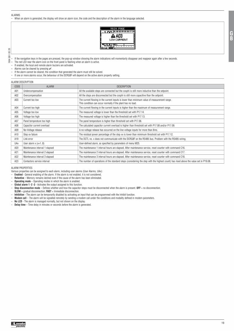
I564 GB I 0
5 20
19
ALARMS– When an alarm is generated, the display will show an alarm icon, the code and the description of the alarm in the language selected.
– If the navigation keys in the pages are pressed, the pop-up window showing the alarm indications will momentarily disappear and reappear again after a few seconds.– The red LED near the alarm icon on the front panel is flashing when an alarm is active.– If enabled, the local and remote alarm buzzers are activated.– Alarms can be cleared by pressing ✔.– If the alarm cannot be cleared, the condition that generated the alarm must still be solved.– If one or more alarms occur, the behaviour of the DCRG8F will depend on the active alarm property setting.
ALARM PROPERTIESVarious properties can be assigned to each alarm, including user alarms (User Alarms, UAx):– Enabled - General enabling of the alarm. If the alarm is not enabled, it is not considered, – Retentive – Memory remains latched even if the cause of the alarm has been eliminated.– Operating mode – Operating modes in which the alarm is enabled.– Global alarm 1 -2 -3 - Activates the output assigned to this function.– Step disconnection mode – Defines whether and how the capacitor steps must be disconnected when the alarm is present. OFF = no disconnection;
SLOW = gradual disconnection; FAST = Immediate disconnection.– Inhibition - The alarm can be temporarily disabled by activating an input that can be programmed with the Inhibit function.– Modem call – The alarm will be signalled remotely by sending a modem call under the conditions and modality defined in modem parameters.– No LCD - The alarm is managed normally, but not shown on the display.– Delay time – Time delay in minutes or seconds before the alarm is generated.
ALARM DESCRIPTION
CODE ALARM DESCRIPTION
A01 Undercompensation All the available steps are connected but the cosphi is still more inductive than the setpoint.
A02 Overcompensation All the steps are disconnected but the cosphi is still more capacitive than the setpoint.
A03 Current too low The current flowing in the current inputs is lower than minimum value of measurement range.This condition can occur normally if the plant has no load.
A04 Current too high The current flowing in the current inputs is higher than the maximum of measurement range.
A05 Voltage too low The measured voltage is lower than the threshold set with P17.14.
A06 Voltage too high The measured voltage is higher than the threshold set with P17.13.
A07 Panel temperature too high The panel temperature is higher than threshold set with P17.06.
A08 Capacitor current overload The calculated capacitor current overload is higher than threshold set with P17.08 and/or P17.09.
A09 No-Voltage release A no-voltage release has occurred on the line voltage inputs for more than 8ms.
A10 Step xx failure The residual power percentage of the step xx is lower than minimum threshold set with P17.12.
A19 Link error The DCTL no. x does not communicate with the DCRG8F on the RS485 bus. Problem with the RS485 wiring.
UAx User alarm x (x=1..8) User-defined alarm, as specified by parameters of menu M25.
A20 Maintenance interval 1 elapsed The maintenance 1 interval hours are elapsed. After maintenance service, reset counter with command C16.
A21 Maintenance interval 2 elapsed The maintenance 2 interval hours are elapsed. After maintenance service, reset counter with command C17.
A22 Maintenance interval 3 elapsed The maintenance 3 interval hours are elapsed. After maintenance service, reset counter with command C18.
A23 Contactors service interval The number of operations of the standard steps (considering the step with the highest count) has rised above the value set in P19.08.
GB

I564 GB I 0
5 20
20
ALARM PROPERTY TABLE
CODE DEFAULT ALARM PROPERTIES
A01 ● ● ● OFF ● 15 ●
A02 ● ● OFF ● 120 ●
A03 ● ● SLO ● 5 ●
A04 ● ● ● OFF ● 120 ●
A05 ● ● ● OFF ● 5 ●
A06 ● ● ● OFF ● 15 ●
A07 ● ● ● SLO ● 30 ●
A08 ● ● ● SLO ● 30 ●
A09 ● IMM ● 0 ●
A10 ● ● ● ● OFF ● 0 ●
A19 ● ● SLO ● 0 ● ●
UA1 OFF 0 ●
UA2 OFF 0 ●
UA3 OFF 0 ●
UA4 OFF 0 ●
UA5 OFF 0 ●
UA6 OFF 0 ●
UA7 OFF 0 ●
UA8 OFF 0 ●
A20 ● OFF ● 0 ●
A21 ● OFF ● 0 ●
A22 ● OFF ● 0 ●
A23 ● OFF ● 0 ●
Enabled
Retentive
Only in AUT
mod
e
Glob
al ala
rm 1
Glob
al ala
rm 2
Glob
al ala
rm 3
Step disc
onnection mod
e
Inhibit
Mod
em
No LCD
Delay
time
min
sec
COMMANDS MENU– The commands menu allows executing some occasional operations, such as measurement reset, counter clearing, alarm reset, etc.– If the advanced access password was entered, the control menu can also be used to perform automatic operations useful for configuring the controller.– The following table lists the functions available in the commands menu, divided by the access level required.
CODE COMMAND ACCESS DESCRIPTIONLEVE
C01 Reset partial energy meter Usr Clears partial energy meter
C02 Reset CNTx counter Usr Clears programmable general counters CNTx
C03 Reset LIMx status Usr Resets status of latched LIMx variables
C04 Reset max temperature Adv Clears maximum temperature peak value
C05 Reset max overload Adv Clears maximum overload peak value
C06 Reset step hour count Adv Clears hour counters of step operation
C07 Reset step switching counters Adv Clears counters of step switchings
C08 Reset step trim Adv Reloads originally programmed power values in step trimming
C09 Reset total energy meter Adv Clears total energy meters
C10 TEST mode activation Adv Enables the TEST mode operation of outputs
C11 Event log reset Adv Clears the event log memory
C12 Setup to default Adv Resets setup programming to factory default
C13 Backup setup Adv Makes a backup copy of user setup of parameters
C14 Restore setup Adv Reloads parameters with the user setup backup
C15 Reset weekly TPF Usr Clears the weekly Total Power Factor stored history
C16 Reset maintenance interval 1 elapsed* Adv Resets the hour counting for service interval 1
C17 Reset maintenance interval 2 elapsed Adv Resets the hour counting for service interval 2
C18 Reset maintenance interval 3 elapsed Adv Resets the hour counting for service interval 3
C19 Reset HI Adv Resets all the highest values
– Once the required command has been selected, press ✔ to execute it. The device will prompt a confirmation. By pressing ✔ again, the command is executed.– To cancel the command execution press ◄.– To quit the commands menu press ◄.* The hour counter can be reset for maintenance interval 1 also by accessing the dedicated page and holding down the ◄ button for three seconds.
GB

I564 GB I 0
5 20
21
MEASUREMENT TABLE FOR LIMIT THRESHOLDS AND ANALOG OUTPUTS– The following table lists all measurements that can be associated with the limit thresholds (menu M20) and analog outputs (menu M23).– The codes selected in the parameters P20.n.01 and P23.n.02 correspond to the measurements below.– To facilitate the comparison with three-phase measurements, some 'virtual' values are provided that are the highest measurements across the three phases. These measurements are identified by the presence of
the word MAX in the measurement code.Example: If you want to apply a maximum limit of 10% on the 5th harmonic current content of the system when you have a three-phase current, set LIM1 toH. I MAX, with channel no. set to 5. The device will consider the highest of the harmonic content of the 5th order among the three currents I L1, I L2 and I L3.
Settings: P20.1.01 = H. I MAX (highest current harmonic among 3 phases) P20.1.02 = 5 (5th harmonic)P20.1.03 = max (compare with max threshold)P.20.1.04 = 10 (threshold = 10%)….
NO. MEASUREMENT CODE DESCRIPTION
00 OFF Measurement disabled
01 V L1-N Phase voltage L1-N
02 V L2-N Phase voltage L2-N
03 V L3-N Phase voltage L3-N
04 I L1 Phase current L1
05 I L2 Phase current L2
06 I L3 Phase current L3
07 V L1-L2 Phase-to-phase voltage L1-L2
08 V L2-L3 Phase-to-phase voltage L2-L3
09 V L3-L1 Phase-to-phase voltage L3-L1
10 W L1 Active power L1
11 W L2 Active power L2
12 W L3 Active power L3
13 var L1 Reactive power L1
14 var L2 Reactive power L2
15 var L3 Reactive power L3
16 VA L1 Apparent power L1
17 VA L2 Apparent power L2
18 VA L3 Apparent power L3
19 Hz Frequency
20 Cosphi L1 Cosphi L1
21 Sinphi L1 Sinephi L1
22 Cosphi L2 Cosphi L2
23 Sinphi L2 Sinephi L2
24 Cosphi L3 Cosphi L3
25 Sinphi L3 Sinephi L3
26 W TOT Total active power
27 var TOT Total reactive power
28 VA TOT Total apparent power
29 Cosphi TOT Cosphi (balanced three-phase system)
30 Sinphi TOT Sinphi (balanced three-phase system)
31 THD VLN MAX THD phase voltage (maximum among phases)
32 THD I MAX THD phase current (maximum among phases)
33 THD VLL MAX THD phase-phase voltage (maximum among phases)
34 H. VLN MAX Phase voltage harmonic content of order n (maximum among phases)
35 H. I MAX Phase current harmonic content of order n (maximum among phases)
36 H. VLL MAX Phase-phase voltage harmonic content of order n (maximum among phases)
37 Cosphi MAX Cosphi (maximum among phases)
38 Sinphi MAX Sinphi (maximum among phases)
39 VLN MAX Phase voltage (maximum among phases)
40 I MAX Current (maximum among phases)
41 VLL MAX Phase-phase voltage (maximum among phases)
42 VLN MIN Phase voltage (minimum among phases)
43 VLL MIN Phase-phase voltage (minimum among phases)
44 Cosphi MIN Cosphi (minimum among phases)
45 AIN Measurement from analog inputs
46 CNT Programmable counter
GB

I564 GB I 0
5 20
22
GB
EVENTS LIST
CODE SYSTEM
E0000 ACTIVATION
E0001 SWITCHING OFF
E0002 SYSTEM RESET
ALARMS
E0200 ALARM START
E0201 ALARM END
E0202 ALARM RESET
E0203 ALARMS ACTIVATED
LIMITS
E0300 ON THRESHOLD
E0301 OFF THRESHOLD
COMMUNICATION
E0500 IR START
E0501 IR END
MODEM
E0600 OUTGOING CALL 1
E0601 OUTGOING CALL 2
E0602 INCOMING CALL
E0603 CALL 1 OK
E0604 CALL 2 OK
E0605 CALL ENDED
E0606 CALL 1 FAILED
E0607 CALL 12 FAILED
E0608 INPUT CALL OK
E0609 INPUT CALL FAILED
E0610 SMS DELIVERY 1
E0611 SMS DELIVERY 2
E0612 SMS DELIVERY 3
E0613 SMS DELIVERY 1 OK
E0614 SMS 2 SENT OK
E0615 SMS 3 SENT OK
E0616 SMS DELIVERY 1 FAILED
E0617 SMS DELIVERY 2 FAILED
E0618 SMS DELIVERY 3 FAILED
E0619 SMS RECEIVED
E0620 SMS RECEIVED OK
E0621 SMS RECEPTION FAILED
E0622 E-MAIL DELIVERY
E0623 E-MAIL DELIVERY OK
E0624 E-MAIL DELIVERY FAILED
E0625 FTP EVENT DELIVERY
E0626 FTP STATUS DELIVERY
E0627 FTP EVENT DELIVERY OK
E0628 FTP STATUS OK
E0629 FTP EV. DELIVERY FAILED
E0630 FTP STATUS FAILED
E0631 GMS RESTART
E0632 GSM SERV. RESET
E0633 PERIODIC CALL
CODE ACCESS
E0700 SETUP MENU ACCESS
E0703 CLOCK SET.ACCESS
COMMANDS
E0800 C01 RES .PART. ENERG.
E0801 C02 RES. CNT
E0802 C03 RESET LIMITS
E0803 C04 RES. MAX. TEMP.
E0804 C05 RESET MAX. OVRL.
E0805 C06 RES. STEP HOURS
E0806 C07 RES. STEP OPER.
E0807 C08 REST. STEP POWR.
E0808 C09 RES. TOT. ENERGY
E0809 C10 REST. TEST MODE
E0810 C11 RES. EVENT MEM.
E0811 C12 SETUP TO DEFAULT
E0812 C13 BACKUP SETUP
E0813 C14 RESTORE SETUP
E0814 C15 RES. WEEKL. TPF K
E0815 C16 RES. MAINTEN. 1
E0816 C17 RES. MAINTEN. 2
E0817 C18 RES. MAINTEN. 3
E0818 C19 RESET HI
PASSWORD
E0900 USER LEVEL
E0901 ADVANCED LEVEL
E0902 REMOTE CONTROL
E0903 UNLOCKING
E0905 CUSTOM SETUP
EXPANSIONS
E1000 NEW CONFIGURATION
MODE CHANGE
E1101 MAN MODE
E1102 AUT MODE
STEP STATUS
E2000 CONNECTED
E2001 DISCONNECTED
DONGLE MENU
E2400 ENABLED
E2401 DISABLED
E2402 SETUP DEVICE TO CX02
E2403 SETUP CX02 TO DEVICE
E2404 CLONE DEVICE TO CX02
E2405 CLONE CX02 TO DEVICE

I564 GB I 0
5 20
23
WIRING DIAGRAMS Thyristor module control with 8 ... 30VDC signal
Thyristor modules control with dry contact (available only for thyristor modules DCTL series)
Command of thyristor modules via RS485 bus (available only for thyristor modules DCTL series)
L1LL1 L2LL2 L3L2 LL2 L3
POWERPPOPOWPOWEPOWER AUXPOWER APOWER AUPOWER AUX
A1
PROG. OUT.
A2 11 14 12
FAN
-
FAN
+ C IN1
NTC
NTC
PROG. IN.
A B
RS485
CONTROL
EXC1042
A1
PROG. OUT.
A2 11 14 12
FAN
-
FAN
+ C IN1
NTC
NTC
PROG. IN.
A B
RS485
CONTROL
EXC1042
INTERFACE CONVERTER
RS232/485
SGTR A B
PC
51C4Cable120R
–+ –+
LLLLL NLL NNLL NN
87
2220 2118
6
1716 19
OUT
SGB
EXP1012
ATR
RS485
EXP1012
RS485
DCRG8FDCTL-1DCTL-XX (MAX32)
SGBATR
Requirements– The DCRG8F controller must be equipped with the optional RS485 communication module code EXP1012– Each DCTL thyristor module must be equipped with the optional RS485 communication card code EXC1042.– With this configuration is possible to monitor from the display of DCRG8F controller the status and the measures of each DCTL thyristor module.– Note. The EXP1012 mounted on DCRG8F controller is dedicated for the command of DCTL thyristor modules. If necessary to connect the DCRG8F controller to a supervision system (e.g. a PC) is necessary to
add another communication expansion module, at choice between the codes compatible with DCRG8F (in the wiring diagram above is shown as example another RS485 module EXP1012). For details see chapter COMMAND OF DCTL THYRISTOR MODULES VIA RS485 BUS.
GB

I564 GB I 0
5 20
24
TERMINAL ARRANGEMENT
SLO
T 1
SLO
T 2
SLO
T 3
SLO
T 4
12 13 14 15 16 17 18 19 20 21 22
1 2 3 4 5 6 7 8 9 10 11
I1 I2 I3 C L1 L2 L3 N nc A1 A2CURRENT INPUT
Ie=5A~VOLTAGE INPUT AUX SUPPLY
100-400V~110-250V=
100-600V~
OU
T 1
OU
T 2
OU
T 3
OU
T 4
OU
T 5
OU
T 6
OU
T 7
OU
T 8
8 x BIDIRECTIONALSOLID STATE RELAYS
nc
40V= 30V~ 120mA MAX
600V~50 / 60 Hz
MECHANICAL DIMENSIONS AND FRONT PANEL CUTOUT [mm]
144
144138
138
35
137
73
64.5
43.3 10
EXP.
..INSTALLATION– DCRG8F is designed for flush-mount installation. With proper mounting, it guarantees IP65 front protection degree.– Insert the controller into the panel cutout, making sure the gasket is properly positioned between the panel surface and the controller front frame.– Make sure the tab of the customising label does not get folded under the gasket and impair the seal gripping. It should be positioned inside the panel.– From inside the panel, for each of the four fixing clips (standard supplied with the controller in plastic bag), position the clip in the appropriate square hole on the controller housing side, then move it backwards in
order to insert its hook in place.
– Repeat the same operation for all four clips.– Tighten the fixing screw with a maximum torque of 0.5Nm.– In case the device needs to be removed, loosen the four clip screws and repeat the steps in reverse order.– For the electrical connections, see the wiring diagrams in the dedicated chapter and the requirements given in the technical characteristics table.
GB

I564 GB I 0
5 20
25
Insulation
Rated insulation voltage Ui 600V~
Rated impulse withstand voltage Uimp 9.5kV
Power frequency withstand voltage 5.2kV
Ambient conditions
Operating temperature -20 to +70°C
Storage temperature -30 to +80°C
Relative humidity <80% (IEC/EN 60068-2-78)
Maximum pollution degree 2
Overvoltage category 3
Measurement category III
Climatic sequence Z/ABDM (IEC/EN 60068-2-61)
Shock resistance 15g (IEC/EN 60068-2-27)
Vibration resistance 0.7g (IEC/EN 60068-2-6)
Connections
Type of terminal Plug-in / removable
Conductor cross section (min-max) 0.2-2.5 mm² (24-12 AWG)
Conductor cross section (min-max) per UL 0,75-2.5 mm² (18-12 AWG)
Tightening torque 0.56 Nm (5 lbin / 4.5 lbin per UL)
Housing
Version Flush mount
Material Polycarbonate
Degree of protection IP65 on front; IP20 terminals
Weight 680g
Certifications and compliance
Certifications obtained cULus, EAC, RCM (pending)
Comply with standards IEC/EN 61010-1, IEC/EN 61000-6-2 IEC/EN 61000-6-4, UL508, CSA C22.2 n°14
∂ Auxiliary supply connected to a line with a phase-neutral voltage ≤300V.
TECHNICAL CHARACTERISTICS
Supply
Rated voltage Us ∂ 100 - 415V~ 110 - 250V
Operating voltage range 90 - 456V~ 93.5 - 300V
Frequency 45 - 66Hz
Power consumption/dissipation 2.5W / 7.5VA (measured with no EXP modules)
Immunity time for microbreakings 110V~ ≥35ms; 220V – 415V~ ≥80ms
Voltage input
Maximum rated voltage Ue 600V~ L-L (346V~ L-N)
Measuring range 50 - 720V L-L (415V~ L-N)
Frequency range 45 - 66Hz / 360 - 440Hz
Measuring method True RMS
Measuring input impedance > 0,55MΩ L-N; > 1,10MΩ L-L
Wiring mode Single-phase, two-phase, three-phase with or without neutral and balanced three-phase system
Current inputs
Rated current Ie 1A~ or 5A~
Measuring range for 1A scale: 0,025 - 1,2A~ for 5A scale: 0,025 - 6A~
Type of input Shunt supplied by an external current transformer (low voltage). Max. 5A
Measuring method True RMS
Overload capacity +20% Ie
Overload peak 50A for 1 second
Power consumption <0.6VA
Measuring accuracy
Line voltage ±0.5% f.s. ±1digit
Static outputs OUT1-8
Type of outputs Solid state relays (OPTO-MOSFET)
Ratings 40V= / 30V~ 120mA max
Calendar-clock (Real time clock-RTC)
Reserve energy Backup capacitor
Operating time without supply voltage About 12...15 days
GB

I564 GB I 0
5 20
26
I
LOVATO ELECTRIC S.P.A.
24020 GORLE (BERGAMO) ITALIAVIA DON E. MAZZA, 12TEL. 035 4282111 E-mail [email protected] www.LovatoElectric.com
DCRG8F
REGOLATORE AUTOMATICO DEL FATTORE DI POTENZA
Manuale operativo
I
ATTENZIONE! – Leggere attentamente il manuale prima dell’utilizzo e l’installazione.– Questi apparecchi devono essere installati da personale qualificato, nel rispetto delle vigenti normative impiantistiche, allo scopo di evitare danni a persone o cose. – Prima di qualsiasi intervento sull’apparecchio, togliere tensione dagli ingressi di misura e di alimentazione e cortocircuitare i trasformatori di corrente.– Il costruttore non si assume responsabilità in merito alla sicurezza elettrica in caso di utilizzo improprio del dispositivo.– I prodotti descritti in questo documento sono suscettibili in qualsiasi momento di evoluzioni o di modifiche. Le descrizioni ed i dati a catalogo non possono pertanto avere alcun valore contrattuale.– Un interruttore o disgiuntore va compreso nell’impianto elettrico dell’edificio. Esso deve trovarsi in stretta vicinanza dell’apparecchio ed essere facilmente raggiungibile da parte dell’operatore. Deve essere
marchiato come il dispositivo di interruzione dell’apparecchio: IEC/EN 61010-1 § 6.11.3.1.– Pulire l’apparecchio con panno morbido; non usare prodotti abrasivi, detergenti liquidi o solventi.
INDICE Pag.Introduzione . . . . . . . . . . . . . . . . . . . . . . . . . . . . . . . . . . . . . . . . . . . . . . . . . . . . . . . . . . . . . . . . . . . . . . . . . . . . . . . . . . . . . . . . . . . . . . . . . . . . . . . . . . . . . . . . . . . . . . . . . . . . . . . . . . . . . . . . . . . . . . . . . . . . . . . . . . . . 27Descrizione . . . . . . . . . . . . . . . . . . . . . . . . . . . . . . . . . . . . . . . . . . . . . . . . . . . . . . . . . . . . . . . . . . . . . . . . . . . . . . . . . . . . . . . . . . . . . . . . . . . . . . . . . . . . . . . . . . . . . . . . . . . . . . . . . . . . . . . . . . . . . . . . . . . . . . . . . . . . . 27Funzione dei tasti frontali . . . . . . . . . . . . . . . . . . . . . . . . . . . . . . . . . . . . . . . . . . . . . . . . . . . . . . . . . . . . . . . . . . . . . . . . . . . . . . . . . . . . . . . . . . . . . . . . . . . . . . . . . . . . . . . . . . . . . . . . . . . . . . . . . . . . . . . . . . . . . . . . . . 27LED frontale . . . . . . . . . . . . . . . . . . . . . . . . . . . . . . . . . . . . . . . . . . . . . . . . . . . . . . . . . . . . . . . . . . . . . . . . . . . . . . . . . . . . . . . . . . . . . . . . . . . . . . . . . . . . . . . . . . . . . . . . . . . . . . . . . . . . . . . . . . . . . . . . . . . . . . . . . . . . . 27Prima messa in tensione . . . . . . . . . . . . . . . . . . . . . . . . . . . . . . . . . . . . . . . . . . . . . . . . . . . . . . . . . . . . . . . . . . . . . . . . . . . . . . . . . . . . . . . . . . . . . . . . . . . . . . . . . . . . . . . . . . . . . . . . . . . . . . . . . . . . . . . . . . . . . . . . . . . 27Modi operativi . . . . . . . . . . . . . . . . . . . . . . . . . . . . . . . . . . . . . . . . . . . . . . . . . . . . . . . . . . . . . . . . . . . . . . . . . . . . . . . . . . . . . . . . . . . . . . . . . . . . . . . . . . . . . . . . . . . . . . . . . . . . . . . . . . . . . . . . . . . . . . . . . . . . . . . . . . . 28Menu principale . . . . . . . . . . . . . . . . . . . . . . . . . . . . . . . . . . . . . . . . . . . . . . . . . . . . . . . . . . . . . . . . . . . . . . . . . . . . . . . . . . . . . . . . . . . . . . . . . . . . . . . . . . . . . . . . . . . . . . . . . . . . . . . . . . . . . . . . . . . . . . . . . . . . . . . . . . 28Accesso tramite password . . . . . . . . . . . . . . . . . . . . . . . . . . . . . . . . . . . . . . . . . . . . . . . . . . . . . . . . . . . . . . . . . . . . . . . . . . . . . . . . . . . . . . . . . . . . . . . . . . . . . . . . . . . . . . . . . . . . . . . . . . . . . . . . . . . . . . . . . . . . . . . . . 28Navigazione fra le pagine del display . . . . . . . . . . . . . . . . . . . . . . . . . . . . . . . . . . . . . . . . . . . . . . . . . . . . . . . . . . . . . . . . . . . . . . . . . . . . . . . . . . . . . . . . . . . . . . . . . . . . . . . . . . . . . . . . . . . . . . . . . . . . . . . . . . . . . . . . . . 29Tabella delle pagine del display . . . . . . . . . . . . . . . . . . . . . . . . . . . . . . . . . . . . . . . . . . . . . . . . . . . . . . . . . . . . . . . . . . . . . . . . . . . . . . . . . . . . . . . . . . . . . . . . . . . . . . . . . . . . . . . . . . . . . . . . . . . . . . . . . . . . . . . . . . . . . . 29Pagina analisi armonica . . . . . . . . . . . . . . . . . . . . . . . . . . . . . . . . . . . . . . . . . . . . . . . . . . . . . . . . . . . . . . . . . . . . . . . . . . . . . . . . . . . . . . . . . . . . . . . . . . . . . . . . . . . . . . . . . . . . . . . . . . . . . . . . . . . . . . . . . . . . . . . . . . . . 30Pagina forme d’onda . . . . . . . . . . . . . . . . . . . . . . . . . . . . . . . . . . . . . . . . . . . . . . . . . . . . . . . . . . . . . . . . . . . . . . . . . . . . . . . . . . . . . . . . . . . . . . . . . . . . . . . . . . . . . . . . . . . . . . . . . . . . . . . . . . . . . . . . . . . . . . . . . . . . . . 31Espandibilità . . . . . . . . . . . . . . . . . . . . . . . . . . . . . . . . . . . . . . . . . . . . . . . . . . . . . . . . . . . . . . . . . . . . . . . . . . . . . . . . . . . . . . . . . . . . . . . . . . . . . . . . . . . . . . . . . . . . . . . . . . . . . . . . . . . . . . . . . . . . . . . . . . . . . . . . . . . . 31Risorse aggiuntive . . . . . . . . . . . . . . . . . . . . . . . . . . . . . . . . . . . . . . . . . . . . . . . . . . . . . . . . . . . . . . . . . . . . . . . . . . . . . . . . . . . . . . . . . . . . . . . . . . . . . . . . . . . . . . . . . . . . . . . . . . . . . . . . . . . . . . . . . . . . . . . . . . . . . . . . 32Canali di comunicazione . . . . . . . . . . . . . . . . . . . . . . . . . . . . . . . . . . . . . . . . . . . . . . . . . . . . . . . . . . . . . . . . . . . . . . . . . . . . . . . . . . . . . . . . . . . . . . . . . . . . . . . . . . . . . . . . . . . . . . . . . . . . . . . . . . . . . . . . . . . . . . . . . . . 32Modem GSM - GPRS . . . . . . . . . . . . . . . . . . . . . . . . . . . . . . . . . . . . . . . . . . . . . . . . . . . . . . . . . . . . . . . . . . . . . . . . . . . . . . . . . . . . . . . . . . . . . . . . . . . . . . . . . . . . . . . . . . . . . . . . . . . . . . . . . . . . . . . . . . . . . . . . . . . . . 32Ingressi, uscite, variabili interne, contatori . . . . . . . . . . . . . . . . . . . . . . . . . . . . . . . . . . . . . . . . . . . . . . . . . . . . . . . . . . . . . . . . . . . . . . . . . . . . . . . . . . . . . . . . . . . . . . . . . . . . . . . . . . . . . . . . . . . . . . . . . . . . . . . . . . . . . 33Soglie limite . . . . . . . . . . . . . . . . . . . . . . . . . . . . . . . . . . . . . . . . . . . . . . . . . . . . . . . . . . . . . . . . . . . . . . . . . . . . . . . . . . . . . . . . . . . . . . . . . . . . . . . . . . . . . . . . . . . . . . . . . . . . . . . . . . . . . . . . . . . . . . . . . . . . . . . . . . . . . 33Variabili da remoto . . . . . . . . . . . . . . . . . . . . . . . . . . . . . . . . . . . . . . . . . . . . . . . . . . . . . . . . . . . . . . . . . . . . . . . . . . . . . . . . . . . . . . . . . . . . . . . . . . . . . . . . . . . . . . . . . . . . . . . . . . . . . . . . . . . . . . . . . . . . . . . . . . . . . . . 34Allarmi utente . . . . . . . . . . . . . . . . . . . . . . . . . . . . . . . . . . . . . . . . . . . . . . . . . . . . . . . . . . . . . . . . . . . . . . . . . . . . . . . . . . . . . . . . . . . . . . . . . . . . . . . . . . . . . . . . . . . . . . . . . . . . . . . . . . . . . . . . . . . . . . . . . . . . . . . . . . . 34Comando moduli a tirisitori serie DCTL via bus RS485 . . . . . . . . . . . . . . . . . . . . . . . . . . . . . . . . . . . . . . . . . . . . . . . . . . . . . . . . . . . . . . . . . . . . . . . . . . . . . . . . . . . . . . . . . . . . . . . . . . . . . . . . . . . . . . . . . . . . . . . . . . . 34Porta di programmazione IR . . . . . . . . . . . . . . . . . . . . . . . . . . . . . . . . . . . . . . . . . . . . . . . . . . . . . . . . . . . . . . . . . . . . . . . . . . . . . . . . . . . . . . . . . . . . . . . . . . . . . . . . . . . . . . . . . . . . . . . . . . . . . . . . . . . . . . . . . . . . . . . . 35Impostazione parametri da PC . . . . . . . . . . . . . . . . . . . . . . . . . . . . . . . . . . . . . . . . . . . . . . . . . . . . . . . . . . . . . . . . . . . . . . . . . . . . . . . . . . . . . . . . . . . . . . . . . . . . . . . . . . . . . . . . . . . . . . . . . . . . . . . . . . . . . . . . . . . . . . 35Impostazione parametri da pannello frontale . . . . . . . . . . . . . . . . . . . . . . . . . . . . . . . . . . . . . . . . . . . . . . . . . . . . . . . . . . . . . . . . . . . . . . . . . . . . . . . . . . . . . . . . . . . . . . . . . . . . . . . . . . . . . . . . . . . . . . . . . . . . . . . . . . . 35Tabella dei parametri . . . . . . . . . . . . . . . . . . . . . . . . . . . . . . . . . . . . . . . . . . . . . . . . . . . . . . . . . . . . . . . . . . . . . . . . . . . . . . . . . . . . . . . . . . . . . . . . . . . . . . . . . . . . . . . . . . . . . . . . . . . . . . . . . . . . . . . . . . . . . . . . . . . . . . 36Tabella funzioni uscite . . . . . . . . . . . . . . . . . . . . . . . . . . . . . . . . . . . . . . . . . . . . . . . . . . . . . . . . . . . . . . . . . . . . . . . . . . . . . . . . . . . . . . . . . . . . . . . . . . . . . . . . . . . . . . . . . . . . . . . . . . . . . . . . . . . . . . . . . . . . . . . . . . . . . 39Tabella funzioni ingressi . . . . . . . . . . . . . . . . . . . . . . . . . . . . . . . . . . . . . . . . . . . . . . . . . . . . . . . . . . . . . . . . . . . . . . . . . . . . . . . . . . . . . . . . . . . . . . . . . . . . . . . . . . . . . . . . . . . . . . . . . . . . . . . . . . . . . . . . . . . . . . . . . . . 39Allarmi . . . . . . . . . . . . . . . . . . . . . . . . . . . . . . . . . . . . . . . . . . . . . . . . . . . . . . . . . . . . . . . . . . . . . . . . . . . . . . . . . . . . . . . . . . . . . . . . . . . . . . . . . . . . . . . . . . . . . . . . . . . . . . . . . . . . . . . . . . . . . . . . . . . . . . . . . . . . . . . . . 44Descrizione degli allarmi . . . . . . . . . . . . . . . . . . . . . . . . . . . . . . . . . . . . . . . . . . . . . . . . . . . . . . . . . . . . . . . . . . . . . . . . . . . . . . . . . . . . . . . . . . . . . . . . . . . . . . . . . . . . . . . . . . . . . . . . . . . . . . . . . . . . . . . . . . . . . . . . . . . 44Proprietà degli allarmi . . . . . . . . . . . . . . . . . . . . . . . . . . . . . . . . . . . . . . . . . . . . . . . . . . . . . . . . . . . . . . . . . . . . . . . . . . . . . . . . . . . . . . . . . . . . . . . . . . . . . . . . . . . . . . . . . . . . . . . . . . . . . . . . . . . . . . . . . . . . . . . . . . . . . 44Tabella allarmi . . . . . . . . . . . . . . . . . . . . . . . . . . . . . . . . . . . . . . . . . . . . . . . . . . . . . . . . . . . . . . . . . . . . . . . . . . . . . . . . . . . . . . . . . . . . . . . . . . . . . . . . . . . . . . . . . . . . . . . . . . . . . . . . . . . . . . . . . . . . . . . . . . . . . . . . . . . 45Menu comandi . . . . . . . . . . . . . . . . . . . . . . . . . . . . . . . . . . . . . . . . . . . . . . . . . . . . . . . . . . . . . . . . . . . . . . . . . . . . . . . . . . . . . . . . . . . . . . . . . . . . . . . . . . . . . . . . . . . . . . . . . . . . . . . . . . . . . . . . . . . . . . . . . . . . . . . . . . 45Tabella misure per soglie limite e uscite analogiche . . . . . . . . . . . . . . . . . . . . . . . . . . . . . . . . . . . . . . . . . . . . . . . . . . . . . . . . . . . . . . . . . . . . . . . . . . . . . . . . . . . . . . . . . . . . . . . . . . . . . . . . . . . . . . . . . . . . . . . . . . . . . . 46Schemi di collegamento . . . . . . . . . . . . . . . . . . . . . . . . . . . . . . . . . . . . . . . . . . . . . . . . . . . . . . . . . . . . . . . . . . . . . . . . . . . . . . . . . . . . . . . . . . . . . . . . . . . . . . . . . . . . . . . . . . . . . . . . . . . . . . . . . . . . . . . . . . . . . . . . . . . 48Disposizione morsetti . . . . . . . . . . . . . . . . . . . . . . . . . . . . . . . . . . . . . . . . . . . . . . . . . . . . . . . . . . . . . . . . . . . . . . . . . . . . . . . . . . . . . . . . . . . . . . . . . . . . . . . . . . . . . . . . . . . . . . . . . . . . . . . . . . . . . . . . . . . . . . . . . . . . . 49Installazione . . . . . . . . . . . . . . . . . . . . . . . . . . . . . . . . . . . . . . . . . . . . . . . . . . . . . . . . . . . . . . . . . . . . . . . . . . . . . . . . . . . . . . . . . . . . . . . . . . . . . . . . . . . . . . . . . . . . . . . . . . . . . . . . . . . . . . . . . . . . . . . . . . . . . . . . . . . . . 49Dimensioni meccaniche e foratura pannello . . . . . . . . . . . . . . . . . . . . . . . . . . . . . . . . . . . . . . . . . . . . . . . . . . . . . . . . . . . . . . . . . . . . . . . . . . . . . . . . . . . . . . . . . . . . . . . . . . . . . . . . . . . . . . . . . . . . . . . . . . . . . . . . . . . . 49Caratteristiche tecniche . . . . . . . . . . . . . . . . . . . . . . . . . . . . . . . . . . . . . . . . . . . . . . . . . . . . . . . . . . . . . . . . . . . . . . . . . . . . . . . . . . . . . . . . . . . . . . . . . . . . . . . . . . . . . . . . . . . . . . . . . . . . . . . . . . . . . . . . . . . . . . . . . . . . 50

I564 GB I 0
5 20
27
I
INTRODUZIONEIl regolatore automatico del fattore di potenza DCRG8F è stato progettato incorporando lo stato dell’arte delle funzioni richieste per le applicazioni di rifasamento dinamico. Realizzato con un contenitore dedicato, didimensioni estremamente compatte, DCRG8F unisce il moderno design del frontale alla praticità di montaggio e alla possibilità di espansione sul retro, dove è possibile alloggiare moduli della serie EXP. Il displaygrafico LCD consente una interfaccia utente chiara ed intuitiva.
DESCRIZIONE– Controllore automatico del fattore di potenza a 8 gradini statici per controllo condensatori, espandibile fino a 24 gradini statici.– Display LCD grafico 128x80 pixel, retroilluminato, 4 livelli di grigio.– 5 tasti di navigazione per funzioni ed impostazioni.– LED rosso di indicazione di allarme / malfunzionamento.– Testi per misure, impostazioni e messaggi in 10 lingue.– Bus di espansione con 4 slot per moduli di espansione serie EXP: • Interfacce di comunicazione RS232, RS485, USB, Ethernet, Profibus, GSM/GPRS • I/O digitali aggiuntivi, uscite statiche o a relè • I/O analogici in tensione, corrente, temperatura PT100 – Funzioni di I/O avanzate programmabili.– Allarmi completamente definibili dall’utente.– Elevata accuratezza delle misure in vero valore efficace (TRMS).– Ingresso di misura tensioni di rete trifase+neutro. – Ingresso di misura correnti trifase. – Interfaccia di programmazione ottica frontale, isolata galvanicamente, alta velocità IP65, compatibile con USB e Wi-Fi. – Orologio datario con riserva di energia. – Memorizzazione ultimi 250 eventi.
FUNZIONE DEI TASTI FRONTALITasto ✔ - Serve per richiamare il menu principale e per confermare una scelta.Tasti s e t - Servono per scorrere le pagine del display o per selezionare la lista di opzioni di un menu.Tasto ◄ - Serve per decrementare una impostazione / selezione oppure per abbandonare un menu.Tasto ► - Serve per scorrere le eventuali sotto-pagine oppure per incrementare una impostazione.
LED FRONTALILED di allarme (rosso) – Lampeggiante indica che un allarme è attivo.
IR
DCRG8F POWER FACTOR CONTROLLER
1
2
3
4
5
1 - Display LCD retroilluminato
2 - Pannello navigazione pagine e menu
3 - LED indicazione allarme attivo
4 - Interfaccia ottica di programmazione
5 - Finestra per etichetta di personalizzazione
PRIMA MESSA IN TENSIONE– Alla prima messa in tensione, l’apparecchio potrà richiedere di impostare l’orologio (RTC) datario, nel caso esso sia fermo.– Successivamente verrà visualizzata una finestra che richiede di specificare la lingua che si vuole utilizzare per la navigazione sul display. Premendo OK (✔) si accederà direttamente al parametro P01.01 per la
selezione della lingua.
– Successivamente verrà ancora visualizzata una finestra che richiede di impostare il primario del TA, cosa che di solito è demandata all’installatore o utilizzatore finale. Anche in questo caso si attiverà un accessodiretto alla impostazione del relativo parametro P02.01.
– La procedura sopra descritta viene ripetuta ad ogni messa in tensione fintanto che non viene impostato il valore del primario del TA nel parametro P02.01.

I564 GB I 0
5 20
28
I
MODI OPERATIVIIl modo operativo selezionato correntemente è visualizzato in negativo al centro della pagina principale. Esistono tre possibili modi operativi, elencati di seguito:
Modo TEST– Quando l’apparecchio é nuovo di fabbrica e non è mai stato programmato, entra automaticamente nel modo TEST che consente all’installatore di attivare manualmente le singole uscite, in modo da poter verificare
la correttezza del cablaggio del quadro.– L’attivazione e la disattivazione delle uscite avviene come per la modalità manuale. – Una volta entrati in programmazione ed impostati i parametri, l’apparecchio esce automaticamente dal modo test.– Se si rende necessario entrare in modo TEST dopo la programmazione dell’apparecchio, utilizzare l’apposito comando del menu comandi.
Modo MAN– Quando l’apparecchio é in modalità manuale, é possibile selezionare uno degli step ed inserirlo o disinserirlo manualmente.– Partendo dalla pagina principale, premere ►. Lo step nr.1 viene evidenziato da un box. Per selezionare lo step desiderato premere il tasto ◄ o ►. – Premere s per inserire oppure t per disinserire lo step selezionato.– Se il numero sopra lo step è in colore grigio chiaro, significa che lo step non è disponibile perché il suo tempo di riconnessione non è ancora esaurito. In questo caso, inviando un comando di chiusura il numero
dello step lampeggerà ad indicare che l’operazione é stata accettata e che verrà eseguita non appena possibile.– La configurazione manuale degli step viene mantenuta anche in assenza della tensione di alimentazione. Quando l’apparecchio viene rialimentato, lo stato originario dei gradini viene ripristinato.
Modo AUT – In modalità automatico l’apparecchio calcola la configurazione di gradini ottimale per raggiungere il cosϕ impostato.– Il criterio di selezione tiene in considerazione molte variabili quali: la potenza dei singoli gradini, il numero di manovre, il tempo totale di utilizzo, il tempo di riconnessione, ecc.– L’apparecchio evidenzia l’imminenza dell’inserzione o disinserzione dei gradini con il lampeggio del loro numero identificativo. Il lampeggio potrebbe protrarsi nei casi in cui l’inserimento di un gradino non è
possibile a causa del tempo di riconnessione (tempo di scarica del condensatore).– Se il numero sopra lo step è in colore grigio chiaro, significa che lo step non è disponibile perché il suo tempo di riconnessione non è ancora esaurito. L’apparecchio attenderà quindi l’esaurimento del tempo di
riconnessione.
MENU PRINCIPALE– Il menu principale è costituito da un insieme di icone grafiche che permettono l’accesso rapido alle misure ed alle impostazioni.– Partendo dalla visualizzazione misure normale, premendo il tasto ✔ il display visualizza il menu rapido.– Premere s o t per ruotare in senso orario/antiorario fino a selezionare la funzione desiderata. L’icona selezionata viene evidenziata e la scritta nella parte centrale del display indica la descrizione della funzione.– Premere ✔ per attivare la funzione selezionata.– Se alcune funzioni non sono disponibili la corrispondente icona sarà disabilitata, cioè visualizzata in colore grigio chiaro.
– ecc - Agiscono come scorciatoie che consentono di velocizzare l’accesso alle pagine di visualizzazione misure, saltando direttamente al gruppo di misure selezionato, partendo dal quale ci sipotrà spostare avanti e indietro come di consueto.
– - Consentono di passare in modo manuale o automatico.
– - Impostazione del codice numerico che consente l’accesso alle funzioni protette (impostazione dei parametri, esecuzione di comandi).
– - Punto di accesso alla programmazione dei parametri. Vedere il capitolo dedicato.
– - Punto di accesso al menu comandi, dove l’utente abilitato può eseguire una serie di azioni di azzeramento e ripristino.
1 - Pagina principale
2 - Passa in modalità manuale
3 - Passa in modalità Automatico
4 - Pagina tensioni - correnti
5 - Lista eventi
6 - Pagina potenze
7 - Statistiche vita step
8 - Armoniche
9 - Informazioni sistema
10 - Menu impostazioni (Setup)
11 - Menu comandi
12 - Inserimento password
ACCESSO TRAMITE PASSWORD– La password serve per abilitare o bloccare l’accesso al menu di impostazione ed al menu comandi.– Per gli apparecchi nuovi di fabbrica (default), la password è disabilitata e l’accesso è libero. Se invece le password sono state abilitate, per ottenere l’accesso bisogna prima inserire il relativo codice di accesso
numerico.– Per abilitare l’uso delle password e definire i codici di accesso fare riferimento al menu di impostazione M15 - Password.– Esistono due livelli di accesso, a seconda del codice inserito: • Accesso livello utente – consente l’azzeramento dei valori registrati e la modifica di alcune impostazioni dell’apparecchio. • Accesso livello avanzato – stessi diritti dell’utente con in più la possibilità di modificare tutte le impostazioni.– Dalla normale visualizzazione misure, premere ✔ per richiamare il menu principale, quindi selezionare l’icona password e premere ✔.– Compare la finestra di impostazione password in figura:
– Con i tasti ◄ e ► ci si sposta fra le cifre. – Con i tasti s e t si cambia il valore della cifra selezionata.– Inserire tutte le cifre della password, quindi spostarsi sull’icona chiave.– Quando la password inserita corrisponde alla Password livello Utente o alla Password livello Avanzato, compare il relativo messaggio di sblocco.– Una volta sbloccata la password, l’accesso rimane abilitato fino a che: • l’apparecchio viene spento. • l’apparecchio viene resettato (in seguito all’uscita dal menu impostazioni). • trascorrono più di 2 minuti senza che l’operatore tocchi alcun tasto. – Con il tasto ✔ si abbandona l’impostazione password e si esce.

I564 GB I 0
5 20
29
I
BLOCCO TASTI FRONTALIE possibile inserire il blocco dei tasti frontali per evitare accessi involari alle pagine di DCRG8F. Per abilitare il blocco dei tasti bisogna posizionarsi sulla pagina principale e successivamente, tendendo premuto il tasto ◄, premere tre volte il tasto s e successivamente per 2 volte il tasto t. Sul display tramite una finestra pop-up verrà notificato l'avvenuto blocco dei tasti. Eseguire la stessa procedura per lo sblocco.
NAVIGAZIONE FRA LE PAGINE DISPLAY – I tasti s e t consentono di scorrere le pagine di visualizzazione misure una per volta. La pagina attuale è riconoscibile tramite la barra del titolo.– Alcune delle misure potrebbero non essere visualizzate in funzione della programmazione e del collegamento dell’apparecchio. – Per alcune pagine sono disponibili delle sotto-pagine accessibili tramite il tasto ► (ad esempio per visualizzare tensioni e correnti sotto forma di barre grafiche).– L’utente ha la possibilità di specificare su quale pagina e su quale sottopagina il display deve ritornare automaticamente dopo che è trascorso un tempo senza che siano premuti dei tasti.– Volendo è anche possibile programmare il regolatore in modo che la visualizzazione resti sempre nella posizione in cui è stata lasciata.– Per l’impostazione di questa funzione vedere il menu M01 – Utilità.
TABELLA DELLE PAGINE DEL DISPLAY
PAGINE ESEMPIO
Pagina principale (Home)
Tensioni e correnti
Potenze
Temperatura
Statistiche step
Armoniche
Forme d’onda
1 - Titolo pagina. Se P01.19 è impostato, viene visualizzato
la descrizione impianto
2 - Stato step: Nero= On Grigio=Off
3 - Stato ventola: Nero= On Grigio=Off
4 - Temperatura quadro
5 - Barra delta kvar
6 - Modo Aut/Man
7 - kvar necessari a raggiungere setpoint
8 - Setpoint cosfi
9 - Cosfi attuale
1 - Barra riferita a TPF = 1.00
1 - Barra riferita alla tensione nominale
2 - Barra riferita alla corrente nominale
1 - Potenza impostata
2 - Potenza misurata
1 - Soglia di allarme
2 - Picco max temperatura con data e ora

I564 GB I 0
5 20
30
I
PAGINE ESEMPIO
Contatori di energia
Lista eventi
Stato espansioni
Orologio datario
Informazioni di sistema
1 - Descrizione evento
2 - Data-ora evento
3 - Numero evento / totali
1 - Con il tasto ► si commutal’indicazione Totali / Parziali
1 - Livello di revisione per: Software
Hardware Parametri
2 - Nome dell’impianto impostato
3 - Temperatura interna delquadro/regolatore
Nota: Alcune delle pagine elencate sopra potrebbero non essere visualizzate, se la relativa funzione non è abilitata. Ad esempio se non viene programmata la funzione limiti, la corrispondente pagina non vienevisualizzata.
PAGINA ANALISI ARMONICA– È possibile abilitare il calcolo e la visualizzazione dell’analisi armonica FFT fino al 31.mo ordine delle seguenti misure: • tensioni concatenate • tensioni di fase • correnti.– Per ognuna di queste misure è disponibile una pagina che rappresenta graficamente il contenuto armonico (spettro) tramite un istogramma a barre.– Ciascuna colonna rappresenta un ordine delle armoniche, pari e dispari. La prima colonna rappresenta il contenuto armonico totale (THD).– Ciascuna colonna dell’istogramma è poi divisa in tre parti che rappresentano il contenuto armonico delle tre fasi L1, L2, L3.– Il valore del contenuto armonico è espresso in percentuale riferita alla ampiezza della armonica fondamentale (frequenza di sistema). – E’ possibile visualizzare il valore del contenuto armonico in forma numerica, selezionando l’ordine desiderato tramite ◄ e ►. In basso viene visualizzato una freccetta che punta alla colonna e il contenuto
armonico percentuale delle tre fasi. – La scala verticale del grafico viene selezionata automaticamente fra quattro valori di fondoscala, in base alla colonna con il valore più alto.
1 - Valori numerici dell’ordineselezionato

I564 GB I 0
5 20
31
I
PAGINA FORME D’ONDA– Questa pagina rappresenta graficamente la forma d’onda dei segnali di tensione e di corrente letti da DCRG8F.– E’ possibile vedere una fase per volta, selezionandola con i tasti ◄ e ►.– La scala verticale (ampiezza) è regolata automaticamente in modo da visualizzare al meglio possibile il segnale.– Sull’asse orizzontale (tempo) vengono visualizzati 2 periodi consecutivi della forma d’onda visualizzata.– Il grafico viene aggiornato automaticamente ogni secondo circa.
ESPANDIBILITÀ– Grazie al bus di espansione, DCRG8F può essere espanso con dei moduli aggiuntivi della serie EXP.– E’ possibile installare un massimo di 4 moduli EXP… contemporaneamente. – I moduli EXP… supportati da DCRG8F si dividono nelle seguenti categorie: • step aggiuntivi • moduli di comunicazione • moduli di I/O digitale • moduli di I/O analogico.– Per inserire un modulo di espansione: • Togliere l’alimentazione a DCRG8F. • Rimuovere uno dei coperchi protettivi degli slot di espansione. • Inserire il gancio superiore del modulo nella apposita feritoia in alto nello slot. • Ruotare il modulo verso il basso inserendo il connettore sul bus. • Premere fino a che l’apposita clip sul lato inferiore del modulo si aggancia a scatto.
– Quando DCRG8F è alimentato, riconoscono automaticamente i moduli EXP... ad essa collegati.– Se la configurazione del sistema è diversa rispetto all’ultima rilevata (è stato aggiunto o rimosso un modulo), l’unità base chiede all’utente di confermare la nuova configurazione. In caso di conferma la nuova
configurazione verrà salvata e diventerà effettiva, altrimenti ad ogni messa in tensione verrà segnalata la discordanza.
– La configurazione attuale del sistema è visualizzata nella apposita pagina del display (moduli espansione), dove si vedono il numero, il tipo e lo stato dei moduli collegati.– La numerazione degli I/O viene elencata sotto ogni modulo.– Lo stato (attivato/disattivato) degli I/O e dei canali di comunicazione viene evidenziato con la scritta in reverse (negativo).
1 - Tipo dei moduli di espansione
2 - Numerazione e stato delle risorse aggiuntive. In reverse = attive

I564 GB I 0
5 20
32
I
RISORSE AGGIUNTIVE– I moduli di espansione forniscono delle risorse aggiuntive che possono essere sfruttate tramite gli opportuni menu di impostazione.– I menu di impostazione che riguardano le espansioni sono disponibili anche se i moduli non sono fisicamente presenti.– Dato che è possibile aggiungere più moduli della stessa tipologia (ad esempio due interfacce di comunicazione) i relativi menu di impostazione sono multipli, identificati da un numero progressivo. – Di seguito una tabella che indica quanti moduli di ogni tipo possono essere montati contemporaneamente e in quali slot possono esere montati. Il numero totale di moduli deve essere ≤ 4.
TIPO MODULO CODICE FUNZIONE Nr. MAX Pos. SLOT
STEP AGGIUNTIVI EXP1001 4 USCITE STATICHE (FAST STEP) 4 Qualsiasi
EXP1006 2 USCITE RELE’ (STEP) 4 Qualsiasi
EXP1007 3 USCITE RELE’ (STEP) 2 1 o 2
COMUNICAZIONE EXP1010 USB 2 Qualsiasi
EXP1011 RS232 2 Qualsiasi
EXP1012 RS485 2 Qualsiasi
EXP1013 Ethernet 1 Qualsiasi
EXP1014 Profibus® DP 1 Qualsiasi
EXP1015 GSM-GPRS (antenna esclusa∂) 1 2
INGRESSI/USCITE EXP1000 4 IN DIGITALI 2 1 o 2
EXP1002 2 IN DIGITALI + 2 USC. STATICI 4 1 o 2
EXP1003 2 USCITE A RELE’ 4 Qualsiasi
EXP1004 2 IN ANALOGICI 2 1 o 2
EXP1005 2 USC. ANALOGICHE 2 1 o 2
EXP1008 2 IN DIGITALI + 2 USCITE A RELE’ 2 1 o 2
ALTRE FUNZIONALITÀ EXP1030 MEMORIA DATI + RTC (c/riserva di carica) 1 1
∂ Antenna cod. CX03 è disponibile e può essere acquistata separatamente.
CANALI DI COMUNICAZIONE– Alla DCRG8F è possibile connettere un massimo di 2 moduli di comunicazione, denominati COMn. Il menu di impostazione comunicazioni prevede quindi due sezioni (n=1 ... 2) di parametri per l’impostazione delle
porte di comunicazione.– I canali di comunicazione sono completamente indipendenti, sia dal punto di vista hardware (tipo di interfaccia fisica) che dal punto di vista del protocollo di comunicazione.– I canali di comunicazione possono funzionare contemporaneamente.– Attivando la funzione Gateway, è possibile avere una DCRG8F equipaggiata con una porta Ethernet ed una porta RS485 che fa da “ponte” verso altri DCRG dotati della sola porta RS485, in modo da ottenere un
risparmio (1 solo punto di accesso Ethernet). – In questa rete, la DCRG8F dotata della porta ethernet avrà il parametro P16.n.09 Funzione canale impostato su Gateway per entrambi i canali di comunicazione (COM1, COM2) mentre gli altri dispositivi
mantengano la configurazione da default = Slave.
MODEM GSM - GPRS– Sul bus di espansione del DCRG8 può essere montato il modulo modem GSM/GPRS cod. EXP 10 15.– Questo modulo consente di semplificare notevolmente l’utilizzo di un modem rispetto alla tradizionale soluzione con un modulo esterno in quanto offre i vantaggi elencati di seguito:– Modem GSM-GPRS quadri-band, adatto al funzionamento in tutte le aree geografiche del mondo. – Alloggiamento incorporato per SIM card.– Connettore SMA per antenna da esterno quadri-band, antivandalo, IP65 (cod. Lovato CX03).Le funzionalità supportate sono riassunte di seguito:– Connessione online (CSD-PSD) Permette di collegarsi online tramite il software di controllo remoto, in seguito ad una chiamata entrante proveninete dal PC oppure chiamando autonomamente un PC in attesa.– Invio SMS con allarmi / stati / eventi Invio di stati ed allarmi via SMS a destinatari multipli. E’ necessario in questo caso specificare i numeri di telefono dei destinatari e le condizioni che generano la chiamata.– Invio e-mail Come per SMS, ma inviato ad un account di posta elettronica.– Ricezione di comandi da SMS Permette di controllare il DCRG8 inviandogli un SMS. I comandi supportati, che possono essere concatenati in un solo messaggio, sono i seguenti:
COMANDI AZIONE
MAN, Cambia modalità operativa da comandoAUT
STPxx=0, Permette di attivare e disattivare uno step, dove xx è il numero relativo dello step (xx=1…32)STPxx=1
REMxx=0 Permette di attivare e disattivare una variabile remota REMxx dove xx è il numero relativo della variabile (xx=1…10)REMxx=1
TIME=ss Attende i secondi ss prima di eseguire i rimanenti comandi
INFO? Richiede stato generale della centralina. L’apparecchio risponde con una stringa come la seguente: ID=DEMO; OM=MAN; MV=411V,413V,412; GV=000V,000V,000V; LC=0000A,0000A,0000A, MC1,GC0; GF=00.0Hz
ALARMS? Richiede lo stato attuale di ogni allarme

I564 GB I 0
5 20
33
I
SOGLIE LIMITE (LIMx)– Le soglie limite LIMn sono delle variabili interne il cui stato dipende dalla fuoriuscita dai limiti definiti dall’utente da parte di una misura fra quelle effettuate dal sistema (esempio: potenza attiva totale superiore a
25kW).– Per velocizzare l’impostazione delle soglie, che possono spaziare in un range estremamente ampio, ciascuna di esse va impostata con un valore base + un coefficiente moltiplicativo (esempio: 25 x 1k = 25000).– Per ogni LIM sono disponibili due soglie (superiore ed inferiore). La soglia superiore deve essere sempre impostata ad un valore maggiore di quella inferiore. – Il significato delle soglie dipende dalle seguenti funzioni: Funzione Min: con la funzione Min la soglia inferiore è d’intervento quella superiore di ripristino. Quando il valore della misura selezionata è sotto il limite inferiore, dopo il ritardo impostato si ha l’attivazione della
soglia. Quando il valore della misura è maggiore della soglia superiore, dopo il ritardo impostato si ha il ripristino. Funzione Max: con la funzione Max la soglia superiore è d’intervento quella inferiore di ripristino. Quando il valore della misura selezionata è maggiore della superiore, dopo il ritardo impostato si ha l’attivazione
della soglia. Quando il valore della misura è minore della soglia inferiore, dopo il ritardo impostato si ha il ripristino. Funzione Min+Max: con la funzione Min+Max le soglie inferiore e superiore sono entrambe d’intervento. Quando il valore della misura selezionata è minore della soglia inferiore o maggiore della soglia superiore,
dopo i rispettivi ritardi si ha l’intervento della soglia. Quando il valore della misura rientra nei limiti si ha il ripristino immediato.– L’intervento può significare eccitazione o diseccitazione del limite LIMn a seconda dell’impostazione.– Se il limite LIMn è impostato con memoria, il ripristino è manuale e può essere effettuato tramite il comando apposito nel menu comandi. – Vedere il menu di impostazione M24.
1 - Tipo di misura
2 - Soglia superiore
3 - Ritardo su soglia
4 - Soglia inferiore
5 - Stato variabile limite
6 - Valore della misura
7 - Funzione
INGRESSI, USCITE, VARIABILI INTERNE, CONTATORI, INGRESSI ANALOGICI– Gli ingressi e le uscite sono identificati da una sigla e da un numero progressivo. Ad esempio gli ingressi digitali sono denominati INPx, dove x rappresenta il numero dell’ingresso. Allo stesso modo, le uscite
digitali sono denominate OUTx.– La numerazione degli ingressi / uscite si basa semplicemente sulla posizione di montaggio dei moduli di espansione, con una numerazione progressiva da sinistra verso destra.– E’ possibile gestire fino a 8 ingressi analogici (AINx) provenienti da sensori esterni (misure di temperatura, consumo, pressione, portata, ecc). Il valore letto dagli ingressi analogici può essere convertito in
qualsiasi unità ingegneristica, visualizzato sul display e reso disponibile sul bus di comunicazione. Le grandezze lette attraverso gli ingressi analogici sono visualizzate sulla apposita pagina. Su di esse possonoessere applicate delle soglie limite LIMx, che a loro volta possono essere collegate ad una uscita interna od esterna.
– La numerazione degli I/O di espansione parte a cominciare dall’ultimo I/O montato sulla unità base. Ad esempio, per le uscite digitali, OUT1…OUT8 sulla unità base, e quindi la prima uscita digitale sui moduli diespansione sarà denominata OUT9. Vedere la seguente tabella per la numerazione degli I/O:
– Allo stesso modo degli ingressi/uscite, esistono delle variabili interne (bit) che possono essere associate alle uscite o combinate fra loro. Ad esempio si possono applicare delle soglie limite alle misure effettuatedal sistema (tensione, corrente etc.). In questo caso la variabile interna, denominata LIMx, sarà attivata quando la misura risulta essere fuori dai limiti definiti dall’utente tramite il relativo menu di impostazione.
– Inoltre sono disponibili fino a 8 contatori (CNT1…CNT8) che possono conteggiare impulsi provenienti dall’esterno (quindi da ingressi INPx) oppure il numero di volte per cui si è verificata una determinatacondizione. Ad esempio definendo una soglia LIMx come sorgente di conteggio, sarà possibile contare quante volte una misura ha superato un certo valore.
– Di seguito una tabella che raccoglie tutte le variabili interne gestite da DCRG8F, con evidenziato il loro range (numero di variabili per tipo).
COD. DESCRIZIONE BASE EXP...
INPx Ingressi digitali - 1…8
OUTx Uscite digitali 1…8 9…24
COMx Porte di comunicazione - 1…2
AINx Ingressi analogici - 1…4
AOUx Uscite analogiche - 1…4
COD. DESCRIZIONE RANGE
LIMx Soglie limite sulle misure 1…16
REMx Variabili controllate da remoto 1…16
UAx Allarmi utente 1…8
PULx Impulsi sul consumo di energia 1…3
CNTx Contatori programmabili 1…8
– Invio dati ed eventi su file remoto tramite server FTP E’ possibile inviare tutti gli eventi registrati dal DCRG8F su un file gestito da un server FTP. In questo modo si può avere sul proprio server la storia aggiornata di tutto quanto è successo sulla centralina in campo.– Le impostazioni necessarie al funzionamento del modem GSM possono essere effettuate tramite l’apposita finestra Parametri modem del software di controllo remoto Xpress.– Una pagina del display visualizza tutte le informazioni riguardanti il modem, in modo da evidenziare le azioni in corso, la qualità del segnale e gli eventuali problemi di connessione.

I564 GB I 0
5 20
34
I
M03 – STEP (n = numero dello step STPn)
PARAMETRO IMPOSTAZIONE DESCRIZIONE
P03.n.02 Statico-485 Lo step numero n connesso al modulo a tiristori DCTL è comandato via bus RS485 dal regolatore DCRG8F
M16 – COMUNICAZIONE (n= numero della porta COM associata al modulo EXP1012)
PARAMETRO IMPOSTAZIONE DESCRIZIONE
P16.n.02 57600 bps Velocità seriale
P16.n.03 8bit - n Formato dati
P16.n.04 1 Bit di stop
P16.n.05 Modbus RTU Protocollo
P16.n.09 Master La porta COM numero n del regolatore DCRG8F è dedicata per il comando dei moduli a tiristori DCTL via bus RS485.
Requisiti– Il regolatore DCRG8F deve essere equipaggiato con il modulo di comunicazione RS485 opzionale codice EXP1012.– Ogni modulo a tiristori DCTL deve essere equipaggiato con la scheda di comunicazione RS485 opzionale codice EXC1042.
Per abilitare il controllo dei moduli a tiristori tramite RS485 è necessario configurare sul regolatore DCRG8F i seguenti parametri:
M01 – GENERALE
PARAMETRO IMPOSTAZIONE DESCRIZIONE
P01.04 1-32 Numero step (=nodo seriale)
In aggiunta è necessario impostare su ogni modulo a tiristori DCTL un nodo seriale differente, che deve corrispondere al numero dello step impostato sul regolatore DCRG8F (esempio: se configuro sulla DCRG8F lostep 3 come “Statico-485”, il corrispondente DCTL deve avere P01.04=3).
I parametri di comunicazione del DCTL sono fissi a velocità=57600bps, formato dati=8bit-n, bit stop =1, protocollo=Modbus RTU.
Nota. In questa configurazione il modulo EXP1012 montato sul regolatore DCRG8F è dedicato al comando dei moduli a tiristori DCTL. Se necessario connettere il regolatore DCRG8F ad un sistema di supervisione (es.un PC) è necessario aggiungere un secondo modulo di comunicazione, a scelta tra le espansioni compatibili con DCRG8F.
VARIABILI DA REMOTO (REMx)– DCRG8F ha la possibilità di gestire un massimo di 16 variabili comandate da remoto (REM1…REM16).– Si tratta di variabili il cui stato può essere modificato a piacere dall’utente tramite il protocollo di comunicazione e che possono essere utilizzate in abbinamento alle uscite.– Esempio: usando una variabile remota (REMx) come sorgente di una uscita (OUTx) sarà possibile attivare e disattivare liberamente un’uscita tramite il software di supervisione. Questo consentirebbe di utilizzare le
uscite di DCRG8F per comandare per comandare dei carichi ad esempio illuminazione o altro.
ALLARMI UTENTE (UAx)– L’utente ha la possibilità di definire un massimo di 8 allarmi programmabili (UA1…UA8).– Per ciascun allarme è possibile stabilire: • la sorgente, cioè la condizione che genera l’allarme; • il testo del messaggio che deve comparire sul display quando questa condizione si verifica; • le proprietà dell’allarme (come per gli allarmi standard), cioè in che modo esso interagisce con il controllo del quadro di rifasamento. – La condizione che genera l’allarme può essere ad esempio il superamento di una soglia. In questo caso la sorgente sarà una delle soglie limite LIMx.– Se invece l’allarme deve essere visualizzato in conseguenza dell’ attivazione di un ingresso digitale esterno, allora la sorgente sarà un INPx.– Per ciascun allarme l’utente ha la possibilità di definire un messaggio liberamente programmabile che comparirà sulla finestra pop-up degli allarmi.– Per gli allarmi utente è possibile definire le proprietà con lo stesso modo utilizzato per gli allarmi normali. Sarà quindi possibile decidere se un determinato allarme deve sconnettere gli step, chiudere l’uscita di
allarme globale ecc. Vedere il capitolo Proprietà degli allarmi.– In caso di presenza contemporanea di più allarmi essi vengono mostrati a rotazione e ne viene indicato il numero totale.– Per azzerare un allarme che è stato programmato con memoria, utilizzare l’apposito comando nel menu comandi.– Per la definizione degli allarmi vedere menu di impostazione M26.
COMANDO MODULI A TIRISITORI SERIE DCTL VIA BUS RS485Il regolatore DCRG8F, se utilizzato in abbinamento a moduli a tiristori Lovato serie DCTL, può comandare i moduli a tiristori tramite bus seriale RS485.Rispetto al comando tramite uscite statiche, questa modalità, oltre a realizzare un cablaggio semplice e lineare su bus, consente di monitorare lo stato e le misure elettriche di ogni modulo a tiristori DCTL (es.temperatura, correnti, tensioni, THDI, potenza residua, ore di lavoro, numero di inserzioni, ecc..) direttamente dal display del regolatore DCRG8F.
È possibile collegare sul bus RS485 un massimo di 32 moduli a tiristori serie DCTL.

I564 GB I 0
5 20
35
I
IMPOSTAZIONE PARAMETRI DA PC – Mediante il software di configurazione e controllo remoto Xpress è possibile effettuare il trasferimento dei parametri (precedentemente impostati) da DCRG8F al disco del PC e viceversa. – Il trasferimento dei parametri da PC a DCRG8F può essere parziale, cioè solo i parametri dei menù specificati.– Oltre ai parametri con il PC è possibile definire: • Logo personalizzato che appare alla messa in tensione ed ogniqualvolta si esce dal setup da tastiera. • Pagina informativa dove poter inserire informazioni, caratteristiche, dati, ecc. concernenti l’applicazione.
IMPOSTAZIONE PARAMETRI (SETUP) DAL PANNELLO FRONTALE– Per accedere al menu di programmazione dei parametri (setup): • predisporre l’apparecchio in modalità MAN e scollegare tutti gli step. • dalla normale visualizzazione misure, premere ✔ per richiamare il menu principale.
• selezionare l’icona . Se essa non è abilitata (visualizzata in grigio) significa che è necessario inserire la password di sblocco (vedere capitolo Accesso tramite password). • premere ✔ per accedere al menu impostazioni.– Viene visualizzata la tabella in figura, con la selezione dei sotto-menu di impostazione, nei quali sono raggruppati tutti i parametri secondo un criterio legato alla loro funzione.– Selezionare il menu richiesto tramite i tasti s e t e confermare con ✔.– Per uscire e tornare alla visualizzazione misure premere ◄.
Setting: Menu selection
– Nella seguente tabella sono elencati i sottomenu disponibili :
COD. MENU DESCRIZIONE
M01 UTILITA’ Lingua, luminosità, pagine display, ecc.
M02 GENERALE Dati caratteristici dell’impianto / quadro
M03 STEP Configurazione step condensatori
M04 USCITE MASTER Configurazione uscite programmabili del DCRG8F
M14 INGRESSI PROG. Funzioni programmabili ingressi digitali
M15 PASSWORD Abilitazione protezione accesso
M16 COMUNICAZIONE Parametri per i canali di comunicazione
M17 PROTEZIONI BASE Protezioni standard del quadro
M19 VARIE Impostazioni varie
M20 SOGLIE LIMITE Soglie sulle misure
M21 CONTATORI Contatori generici programmabili
M22 ING. ANALOGICI Ingressi analogici programmabili
M23 USCITE ANALOGICI Uscite analogiche programmabili
M24 IMPULSI ENERGIA Impulsi incremento contatori di energia
M25 ALLARMI UTENTE Allarmi utenti programmabili
M26 PROPRIETA’ ALLARMI Azioni provocate dagli allarmi
PORTA DI PROGRAMMAZIONE IR– La configurazione dei parametri di DCRG8F si può effettuare tramite la porta ottica frontale, attraverso la chiavetta di programmazione IR-USB tipo CX01 oppure la chiavetta IR-WiFi tipo CX02. – Questa porta di programmazione ha i seguenti vantaggi: • Consente di effettuare la configurazione e la manutenzione di DCRG8F senza la necessità di accedere al retro dell’apparecchio e quindi di aprire il quadro elettrico. • E’ galvanicamente isolata dalla circuiteria interna di DCRG8F, garantendo la massima sicurezza per l’operatore. • Consente una elevata velocità di trasferimento dei dati. • Consente una protezione frontale IP65. • Restringe la possibilità di accessi non autorizzati alla configurazione del dispositivo.– Semplicemente avvicinando una chiavetta CX.. alla porta frontale ed inserendo le spine negli appositi fori, si otterrà il vicendevole riconoscimento dei dispositivi evidenziato dal colore verde del LED LINK sulla
chiavetta di programmazione.
Chiavetta di programmazione USB tipo CX01

I564 GB I 0
5 20
36
I
– Selezionare il sotto-menu e premere il tasto ✔ per visualizzare i parametri.– Tutti i parametri sono visualizzati con codice, descrizione, valore attuale.
– Se si vuole modificare il valore di un parametro, dopo averlo selezionato premere ✔.– Se non è stata immessa la password livello Avanzato, non sarà possibile accedere alla pagina di modifica, e verrà visualizzato un messaggio di accesso negato.– Se invece si ha l’accesso, verrà visualizzata la pagina di modifica.
– Quando si è in modalità modifica, il valore può essere modificato con i tasti ◄ e ►. Vengono visualizzati anche una barra grafica che indica il range di impostazione, i valori minimi e massimi possibili, il valoreprecedente e quello di default.
– Premendo ◄ + s il valore viene impostato al minimo possibile, mentre con s + ► viene impostato al massimo.– Premendo contemporaneamente ◄ + ► l’impostazione viene riportata al valore di default di fabbrica.– Durante l’impostazione di un testo, con i tasti s e t si seleziona il carattere alfanumerico e con ◄ e ► si sposta il cursore all’interno del testo. Premendo contemporaneamente s e t la selezione alfanumerica
si posiziona direttamente sul carattere ‘A’.– Premere ✔ per tornare alla selezione parametri. Il valore immesso rimane memorizzato.– Premere ◄ per salvare i cambiamenti ed uscire dalla impostazione. Il regolatore esegue un reset e ritorna in funzionamento normale.– Se non vengono premuti tasti per 2 minuti consecutivi, il menu setup viene abbandonato automaticamente e il sistema torna alla visualizzazione normale senza salvare i parametri.– Si rammenta che per i soli dati di setup modificabili da tastiera, è possibile fare una copia di sicurezza (backup) nella memoria eeprom di DCRG8F. Questi stessi dati all’occorrenza possono essere ripristinati
(restore) nella memoria di lavoro. I comandi di copia di sicurezza e ripristino dei dati sono disponibili nel menù comandi.
Impostazione: selezione parametri
Impostazione: pagina di modifica
1 - Codice parametro
2 - Valore attuale
3 - Parametro selezionato
4 - Descrizione parametro
1 - Parametro selezionato
2 - Nuovo valore impostato
3 - Massimo valore possibile
4 - Valore di default
5 - Barra grafica valore-range
6 - Minimo valore possibile
TABELLA DEI PARAMETRI– Di seguito vengono riportati tutti i parametri di programmazione disponibili in forma tabellare. Per ogni parametro sono indicati il range di impostazione possibile ed il default di fabbrica, oltre ad una spiegazione
della funzionalità del parametro. La descrizione del parametro visibile sul display può in qualche caso differire da quanto riportato in tabella a causa del ridotto numero di caratteri disponibile. Il codice delparametro vale comunque come riferimento.
Nota: I parametri evidenziati nella tabella con uno sfondo grigio sono essenziali al funzionamento dell’impianto, rappresentano quindi la programmazione minima indispensabile per la messa in funzione.
P01.01 – Selezione lingua per i testi sul display.P01.02 – Attivazione accesso automatico al setup dell’orologio dopo una messa in tensione.P01.03 – Regolazione del contrasto del LCD. P01.04 – Regolazione della retroilluminazione alta del display.P01.05 – Regolazione della retroilluminazione bassa del display.P01.06 – Ritardo passaggio a retroilluminazione bassa del display.P01.07 – Ritardo di ripristino della visualizzazione della pagina di default quando non vengono premuti tasti. Se impostato a OFF il display rimane sempre sulla ultima pagina selezionata manualmente.P01.08 – Pagina di default visualizzata dal display alla accensione e dopo il ritardo.P01.09 – Testo libero con nome alfanumerico identificativo dello specifico impianto. Se viene impostata una descrizione, questa comparirà come titolo della pagina principale. Usata anche come identificazione per
telesegnalazione via SMS/E-mail.
M01 – UTILITA’ UdM Default Range
P01.01 Lingua English English Italian French Spanish Portuguese German Polish Czech Russian Custom
P01.02 Impostazione orologio alla alimentazione sistema OFF OFF – ON
P01.03 Contrasto LCD % 50 0-100
P01.04 Intensità retroilluminazione display alta % 100 0-100
P01.05 Intensità retroilluminazione display bassa % 25 0-50
P01.06 Tempo passaggio a retroilluminazione bassa s 180 5-600
P01.07 Ritorno a pagina di default s 60 OFF / 10-600
P01.08 Pagina di default main (elenco pagine)
P01.09 Descrizione impianto (vuoto) (Stringa 20 car.)

I564 GB I 0
5 20
37
I
M02 - GENERALE UdM Default Range
P02.01 Primario TA A OFF OFF/1-30000
P02.02 Secondario TA A 5 1 / 5
P02.03 Tipologia impianto Trifase Trifase / Monofase
P02.04 Fase lettura correnti L3 L1 / L2 / L3 / L1-L2-L3
P02.05 Verso collegamento TA Aut Aut - Dir - Inv
P02.06 Fase lettura tensioni L1-L2 L1-L2 / L2-L3 / L3-L1 / L1-N / L2-N / L3-N / L1-L2-L3 / L1-L2-L3-N
P02.07 Potenza step più piccolo kvar 1.00 0.01 – 10000
P02.08 Tensione nominale condensatori V 400 50 – 50000
P02.09 Frequenza nominale Hz Aut Aut / 50Hz / 60Hz / Variabile
P02.10 Tempo di riconnessione s 60 1-30000
P02.11 Sensibilità s 60 1-1000
P02.12 Sensibilità alla disconnessione s OFF OFF / 1 – 600
P02.13 Setpoint cosfi 1 (standard) 0.95 IND 0.50 IND – 0.50 CAP
P02.14 Setpoint cosfi 2 0.95 IND 0.50 IND – 0.50 CAP
P02.15 Setpoint cosfi 3 0.95 IND 0.50 IND – 0.50 CAP
P02.16 Setpoint cosfi generazione 0.95 IND 0.50 IND – 0.50 CAP
P02.17 Tolleranza + su setpoint 0.00 0 – 0.10
P02.18 Tolleranza - su setpoint 0.00 0 – 0.10
P02.19 Disconnessione step in generazione OFF OFF - ON
P02.20 Corrente nominale impianto A Aut Aut / 1 - 30000
P02.21 Tensione nominale impianto V Aut Aut / 100 - 60000
P02.22 Tipo di tensione impianto BT BT - BT / MT
P02.23 Utilizzo TV OFF OFF - ON
P02.24 Primario TV1 V 100 50-50000
P02.25 Secondario TV1 V 100 50-500
P02.26 Primario TV2 V 100 50-50000
P02.27 Secondario TV2 V 100 50-500
P02.28 Modo inserzione step Fast Standard / Lineare Fast
P02.29 Ritardo inserzione statica cicli 3 1-50
P02.30 Abilitazione setpoint Tanfi OFF OFF - ON
P02.31 Setpoint Tanfi 0 -1.732 a +1.732
P02.32 Modo sensibilità Proporzionale Proporzionale – Fissa
P02.33 Setpoint tanfi generazione 0 -1.732 a +1.732
P02.34 Correzione angolo ° 0 0-359
P.02.35 Tempo tra commutazioni s 4.0 0.5-5.0
P02.01 – Valore del primario dei trasformatori di corrente. Esempio: con TA 800/5A impostare 800. Se impostato su OFF, alla messa in tensione l’apparecchio richiederà di impostare il TA e permetterà l’accessodiretto a questo parametro.
P02.02 – Valore del secondario dei trasformatori di corrente. Esempio: con TA 800/5A impostare 5. P02.04 – Definisce su quali e su quante fasi l’apparecchio legge il segnale di corrente. Il collegamento degli ingressi amperometrici deve coincidere con quanto impostato in questo parametro.
Sono supportate tutte le combinazioni possibili con il parametro P02.06.P02.05 – Lettura della polarità di collegamento dei TA.
Aut = La polarità è riconosciuta automaticamente alla messa in tensione. Utilizzabile solo quando si lavora con un solo TA e quando l’impianto non ha alcun dispositivo generatore.Dir = Riconoscimento automatico disabilitato. Collegamento diretto.Inv = Riconoscimento automatico disabilitato. Collegamento inverso.
P02.06 – Definisce su quali e su quante fasi l’apparecchio legge il segnale di tensione. Il collegamento degli ingressi voltmetrici deve coincidere con quanto impostato in questo parametro. Sono supportate tutte le combinazioni possibili con il parametro P02.04.
P02.07 – Valore in kvar dello step più piccolo installato (equivalente al peso 1). Potenza di targa del banco di condensatori erogato alla tensione di targa specificata in P02.08 e riferito al totale dei tre condensatori sein applicazione trifase.
P02.08 – Tensione nominale di targa dei condensatori, alla quale viene erogata la potenza specificata in P02.07. Se i condensatori sono utilizzati ad un tensione diversa (inferiore) rispetto a quella nominale, la potenzarisultante viene ricalcolata automaticamente dall’apparecchio.
P02.09 – Frequenza di lavoro dell’impianto. Aut = selezione automatica fra 50 e 60 Hz alla messa in tensione. 50Hz = fissa a 50 Hz. 60Hz = fissa a 60 Hz. Variabile = misurata continuamente ed adattata. P02.10 – Tempo minimo che deve trascorrere fra la disconnessione di uno step e la successiva riconnessione sia in MAN che in AUT.
Durante questo tempo il numero dello step sulla pagina principale è indicato in grigio chiaro. P02.11 – Sensibilità alla connessione. Parametro che imposta la velocità di reazione del regolatore. Con valori bassi la regolazione è veloce (maggior precisione intorno al setpoint ma maggior numero di manovre).
Con valori alti invece si hanno reazioni più lente della regolazione, con minor numero di manovre degli step. Il tempo di ritardo alla reazione è inversamente proporzionale alla richiesta di step per raggiungere il setpoint: tempo attesa = (sensibilità / numero di step richiesti).Esempio: impostando la sensibilità a 60s, se viene richiesta l’inserzione di uno step di peso 1 vengono attesi 60s (60/1 = 60) . Se invece servono un totale di 4 step verranno attesi 15s (60 / 4 = 15).
P02.12 – Sensibilità alla disconnessione. Come parametro precedente ma riferita alla disconnessione. Se impostata ad OFF la disconnessione ha gli stessi tempi di reazione della connessione regolata con il parametro precedente.
P02.13 – Setpoint (valore da raggiungere) del cosfi. Valore utilizato in applicazioni standard.P02.14 – P02.15 – Setpoint alternativi, selezionabili via combinazioni di ingressi digitali programmati con l’apposita funzione.P02.16 – Setpoint utilizzato quando l’impianto sta generando potenza attiva verso il fornitore. P02.17 – P02.18 – Tolleranza intorno al setpoint. Quando il cosfi si trova all’interno della fascia delimitata da questi parametri, in AUT non vengono inseriti/disinseriti dei step anche se il delta-kvar è maggiore dello
step più piccolo.Nota: + significa “verso induttivo”, – significa “verso capacitivo”.
P02.19 – Se impostato ad ON, quando il sistema sta cedendo potenza attiva al fornitore (generazione = potenza attiva e cosfi negativi) tutti gli step vengono scollegati.P02.20 – Corrente nominale dell’impianto. Valore utilizzato per il fondoscala delle barre grafiche e per l’impostazione delle soglie di corrente espresse in percentuale. Se impostato su Aut viene utilizzato il valore di
P02.01 (primario TA).
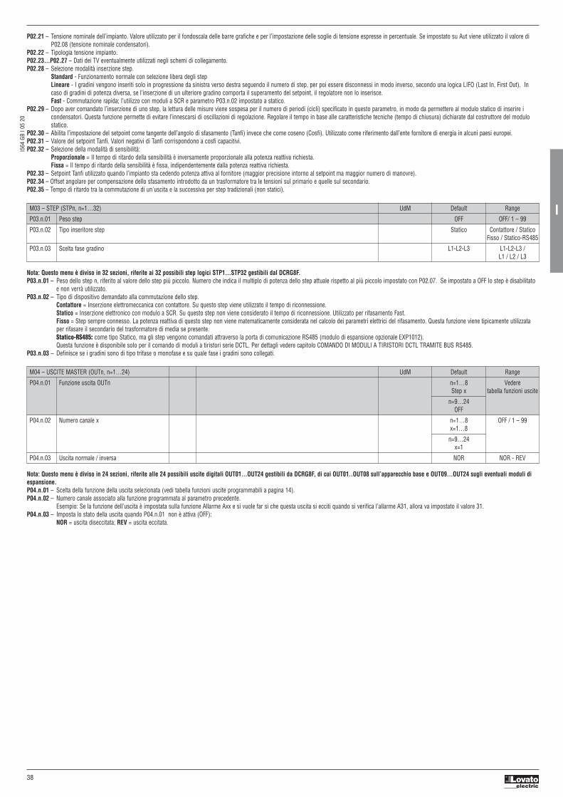
I564 GB I 0
5 20
38
I
Nota: Questo menu è diviso in 24 sezioni, riferite alle 24 possibili uscite digitali OUT01…OUT24 gestibili da DCRG8F, di cui OUT01..OUT08 sull’apparecchio base e OUT09…OUT24 sugli eventuali moduli diespansione.P04.n.01 – Scelta della funzione della uscita selezionata (vedi tabella funzioni uscite programmabili a pagina 14).P04.n.02 – Numero canale associato alla funzione programmata al parametro precedente.
Esempio: Se la funzione dell’uscita è impostata sulla funzione Allarme Axx e si vuole far si che questa uscita si ecciti quando si verifica l’allarme A31, allora va impostato il valore 31. P04.n.03 – Imposta lo stato della uscita quando P04.n.01 non è attiva (OFF):
NOR = uscita diseccitata; REV = uscita eccitata.
M03 – STEP (STPn, n=1…32) UdM Default Range
P03.n.01 Peso step OFF OFF/ 1 – 99
P03.n.02 Tipo inseritore step Statico Contattore / Statico Fisso / Statico-RS485
P03.n.03 Scelta fase gradino L1-L2-L3 L1-L2-L3 / L1 / L2 / L3
M04 – USCITE MASTER (OUTn, n=1…24) UdM Default Range
P04.n.01 Funzione uscita OUTn n=1…8 Vedere Step x tabella funzioni uscite
n=9…24 OFF
P04.n.02 Numero canale x n=1…8 OFF / 1 – 99 x=1…8
n=9…24 x=1
P04.n.03 Uscita normale / inversa NOR NOR - REV
P02.21 – Tensione nominale dell’impianto. Valore utilizzato per il fondoscala delle barre grafiche e per l’impostazione delle soglie di tensione espresse in percentuale. Se impostato su Aut viene utilizzato il valore diP02.08 (tensione nominale condensatori).
P02.22 – Tipologia tensione impianto.P02.23…P02.27 – Dati dei TV eventualmente utilizzati negli schemi di collegamento.P02.28 – Selezione modalità inserzione step.
Standard - Funzionamento normale con selezione libera degli stepLineare - I gradini vengono inseriti solo in progressione da sinistra verso destra seguendo il numero di step, per poi essere disconnessi in modo inverso, secondo una logica LIFO (Last In, First Out). Incaso di gradini di potenza diversa, se l’inserzione di un ulteriore gradino comporta il superamento del setpoint, il regolatore non lo inserisce.Fast - Commutazione rapida; l’utilizzo con moduli a SCR e parametro P03.n.02 impostato a statico.
P02.29 – Dopo aver comandato l’inserzione di uno step, la lettura delle misure viene sospesa per il numero di periodi (cicli) specificato in questo parametro, in modo da permettere al modulo statico di inserire icondensatori. Questa funzione permette di evitare l’innescarsi di oscillazioni di regolazione. Regolare il tempo in base alle caratteristiche tecniche (tempo di chiusura) dichiarate dal costruttore del modulostatico.
P02.30 – Abilita l’impostazione del setpoint come tangente dell’angolo di sfasamento (Tanfi) invece che come coseno (Cosfi). Utilizzato come riferimento dall’ente fornitore di energia in alcuni paesi europei.P02.31 – Valore del setpoint Tanfi. Valori negativi di Tanfi corrispondono a cosfi capacitivi.P02.32 – Selezione della modalità di sensibilità:
Proporzionale = Il tempo di ritardo della sensibilità è inversamente proporzionale alla potenza reattiva richiesta.Fissa = Il tempo di ritardo della sensibilità è fissa, indipendentemente dalla potenza reattiva richiesta.
P02.33 – Setpoint Tanfi utilizzato quando l’impianto sta cedendo potenza attiva al fornitore (maggior precisione intorno al setpoint ma maggior numero di manovre).P02.34 – Offset angolare per compensazione dello sfasamento introdotto da un trasformatore tra le tensioni sul primario e quelle sul secondario.P02.35 – Tempo di ritardo tra la commutazione di un'uscita e la successiva per step tradizionali (non statici).
Nota: Questo menu è diviso in 32 sezioni, riferite ai 32 possibili step logici STP1…STP32 gestibili dal DCRG8F.P03.n.01 – Peso dello step n, riferito al valore dello step più piccolo. Numero che indica il multiplo di potenza dello step attuale rispetto al più piccolo impostato con P02.07. Se impostato a OFF lo step è disabilitato
e non verrà utilizzato. P03.n.02 – Tipo di dispositivo demandato alla commutazione dello step.
Contattore = Inserzione elettromeccanica con contattore. Su questo step viene utilizzato il tempo di riconnessione. Statico = Inserzione elettronico con modulo a SCR. Su questo step non viene considerato il tempo di riconnessione. Utilizzato per rifasamento Fast.Fisso = Step sempre connesso. La potenza reattiva di questo step non viene matematicamente considerata nel calcolo dei parametri elettrici del rifasamento. Questa funzione viene tipicamente utilizzataper rifasare il secondario del trasformatore di media se presente.Statico-RS485: come tipo Statico, ma gli step vengono comandati attraverso la porta di comunicazione RS485 (modulo di espansione opzionale EXP1012). Questa funzione è disponibile solo per il comando di moduli a tiristori serie DCTL. Per dettagli vedere capitolo COMANDO DI MODULI A TIRISTORI DCTL TRAMITE BUS RS485.
P03.n.03 – Definisce se i gradini sono di tipo trifase o monofase e su quale fase i gradini sono collegati.

I564 GB I 0
5 20
39
I
M14 – INGRESSI PROGRAMMABILI (INPn, n=1…8) UdM Default Range
P14.n.01 Funzione Ingresso INPn (varie) (Vedi Tabella funzioni ingressi)
P14.n.02 Numero canale x OFF OFF / 1-99
P14.n.03 Tipo contatto NO NO/NC
P14.n.04 Ritardo eccitazione s 0.05 0.00-600.00
P14.n.05 Ritardo diseccitazione s 0.05 0.00-600.00
Nota: Questo menu è diviso in 8 sezioni, riferite ai 8 possibili ingressi digitali P14.n.01 – Scelta della funzione dell’ingresso selezionato (vedi tabella funzioni ingressi programmabili).P14.n.02 – Numero canale eventualmente associato alla funzione programmata al parametro precedente.
Esempio: Se la funzione dell’ingresso è impostata su Selezione setpoint cosfi x, e si vuole far si che questo ingresso selezioni il cosfi 3, allora va impostato il valore 3. P14.n.03 – Scelta del tipo di contatto: NO normalmente aperto o NC normalmente chiuso.P14.n.04 – Ritardo alla chiusura del contatto sull’ingresso selezionato.P14.n.05 – Ritardo all’apertura del contatto sull’ingresso selezionato.
M15 – PASSWORD UdM Default Range
P15.01 Utilizzo password OFF OFF-ON
P15.02 Password livello Utente 1000 0-9999
P15.03 Password livello Avanzato 2000 0-9999
P15.04 Password accesso remoto OFF OFF/1-9999
P15.01 – Se impostato ad OFF, la gestione delle password è disabilitata e l’accesso alle impostazioni e al menu comandi è libero. P15.02 – Con P15.01 attivo, codice numerico da specificare per attivare l’accesso a livello Utente. Vedere capitolo Accesso tramite password.P15.03 – Come P15.02, riferito all’accesso livello Avanzato.P15.04 – Se impostato ad un valore numerico, diventa il codice da specificare via comunicazione seriale prima di poter inviare comandi da controllo remoto.
TABELLA FUNZIONI INGRESSI– La tabella seguente riporta tutte le funzioni che possono essere associate agli ingressi digitali programmabili INPn. – Ciascun ingresso può essere poi impostato in modo da avere funzione invertita (NA - NC), essere ritardato alla eccitazione oppure alla diseccitazione con tempi impostabili indipendenti.– Alcuni funzioni necessitano di un ulteriore parametro numerico, definito con il numero canale x specificato dal parametro P14.n.02.– Vedere menu M14 Ingressi programmabili per maggiori dettagli.
FUNZIONE DESCRIZIONE
OFF Ingresso disabilitato
Configurabile Libera configurazione INPx . Ad esempio per generare un allarme utente UA, o contare su un contatore CNT.
Modo Automatico Se attivato passa in modo automatico
Modo Manuale Se attivato passa in modo manuale
Selezione setpoint cosfi x Se attivato seleziona il setpoint cosfi x (x=1…3).
Blocco tastiera Blocca operatività dei tasti frontali.
Blocco impostazioni Impedisce accesso a setup/menu comandi.
Inibizione allarmi Disabilita selettivamente gli allarmi che hanno la proprietà Inibizione a ON.
Comando Cxx Se attivato esegue il comando Cxx (vedere MENU COMANDI)
TABELLA FUNZIONI USCITE– La tabella seguente riporta tutte le funzioni che possono essere associate alle uscite digitali programmabili OUTn. – Ciascuna uscita può essere poi impostato in modo da avere funzione normale o invertita (NOR o REV).– Alcuni funzioni necessitano di un ulteriore parametro numerico, definito con il numero canale x specificato dal parametro P04.n.02.– Vedere il menu M04 USCITE MASTER per maggiori dettagli.
FUNZIONE DESCRIZIONE
OFF Uscita sempre diseccitata
ON Uscita sempre eccitata
Step x Step rifasamento nr.x
Allarme Globale 1 Attivata quando allarme globale 1 è attivo
Allarme Globale 2 Attivata quando allarme globale 2 è attivo
Allarme Globale 3 Attivata quando allarme globale 3 è attivo
Ventilatore Attivazione ventilatore
Modo manuale Attivata quando il regolatore è in modo manuale
Modo automatico Attivata quando il regolatore è in modo automatico
Limiti LIM x Uscita comandata da limiti (x=1...16)
Impulsi PULx Uscita da impulsi energia (x=1…6)
Variabile remota REM x Uscita comandata da remoto (x=1...16)
Allarmi A01-Axx Quando l’allarme Axx selezionato è presente l’uscita digitale viene attivata (x=1…Numero allarmi)
Allarmi UA1..UAx Quando l’allarme utente UAx selezionato è presente l’uscita digitale viene attivata (x=1…8)

I564 GB I 0
5 20
40
I
M16 – COMUNICAZIONE (COMn, n=1…2) UdM Default Range
P16.n.01 Indirizzo seriale nodo 01 01-255
P16.n.02 Velocità seriale bps 9600 1200 2400 4800 9600 19200 38400 57600 115200
P16.n.03 Formato dati 8 bit – n 8 bit - n (no parità) 8 bit, dispari 8 bit, pari 7 bit, dispari 7 bit, pari
P16.n.04 Bit di stop 1 1-2
P16.n.05 Protocollo Modbus RTU Modbus RTU Modbus ASCII Modbus TCP
P16.n.06 Indirizzo IP 192.168.1.1 000.000.000.000 – 255.255.255.255
P16.n.07 Subnet mask 255.255.255.0 000.000.000.000 – 255.255.255.255
P16.n.08 TCP-IP port 1001 0-9999
P16.n.09 Funzione canale Slave Slave / Gateway / Mirror / Master
P16.n.10 Client / server Server Client / Server
P16.n.11 Indirizzo IP remoto 000.000.000.000 000.000.000.000 – 255.255.255.255
P16.n.12 Porta IP remota 1001 0-9999
P16.n.13 Indirizzo gateway IP 000.000.000.000 000.000.000.000 – 255.255.255.255
Nota: Questo menu è diviso in 2 sezioni, per i canali di comunicazione COM1...2. La porta di programmazione frontale a infrarossi ha parametri di comunicazione fissi e quindi non necessita di impostazione.P16.n.01 – Indirizzo seriale (nodo) del protocollo di comunicazione.P16.n.02 – Velocità di trasmissione della porta di comunicazione.P16.n.03 – Formato dati. Impostazioni a 7 bit possibili solo per protocollo ASCII.P16.n.04 – Numero bit di stop.P16.n.05 – Scelta del protocollo di comunicazione.P16.n.06...P16.n.08 – Coordinate TCP-IP per applicazioni con interfaccia Ethernet. Non utilizzati con altri tipi di moduli di comunicazione.P16.n.09 – Ruolo del canale di comunicazione. Slave = Slave modbus; Gateway = Ponte fra porta Ethernet e porta seriale.
Mirror = Funzione di mirror del pannello (riservato / funzione non disponibile). Master = la porta RS485 è utilizzata per il comando degli step (disponibile solo per moduli a tiristori serie DCTL).P16.n.10 – Attivazione della connessione TCP-IP. Server = Attende connessione da un client remoto. Client = Stabilisce connessione verso un server remoto.P16.n.11...P16.n.13 – Coordinate per la connessione al server remoto quando P16.n.10 è impostato a client.
M17 – PROTEZIONI BASE UdM Default Range
P17.01 Unità di misura temperatura °C °C / °F
P17.02 Sorgente misura temperatura Interno quadro Sens. Interno Sens. Interno / AINx
P17.03 Numero canale x 1 1-99
P17.04 Temperatura start ventilatore ° 50 0-212
P17.05 Temperatura stop ventilatore ° 45 0-212
P17.06 Soglia allarme temperatura interno quadro ° 55 0-212
P17.07 Controllo sovraccarico condensatori ON OFF / ON
P17.08 Soglia allarme sovraccarico corrente condensatori % 125 OFF / 100 – 150
P17.09 Soglia disconnessione immediata step % 150 OFF / 100 – 200
P17.10 Tempo reset allarme sovraccarico min 5 1 – 30
P17.11 Aggiustamento potenza step OFF OFF - ON
P17.12 Soglia allarme step difettoso % OFF OFF / 25…100
P17.13 Soglia allarme tensione massima % 120 OFF / 90...150
P17.14 Soglia allarme tensione minima % OFF OFF / 60..110
P17.02 – Definisce da quale sensore viene preevata la misura di temperatura interno quadro: Sensore interno – Sensore incorporato nel controllerAINx – Temperatura da ingresso PT100 su modulo di espansione EXP1004.
P17.03 – Numero canale riferito al parametro precedente.P17.04 – P17.05 – Temperature di start e stop ventola di raffreddaento del quadro, espresse nell’unità di misura impostata con P17.01.
È possibbile inoltre forzare lo start della ventola per un tempo di 30 secondi andando nella pagina dedicata alla temperatura e tenendo premuto il tasto ◄ per tre secondi.P17.06 – Soglia di allarme per la generazione dell’allarme A07 - Temperatura troppo alta.P17.07 – Abilita la misura della corrente di sovraccarico condensatori calcolata dalla forma d’onda della tensione applicata.
Nota: E’ possibile utilizzare questa protezione solo se i condensatori non hanno dispositivi di filtro quali induttanze o altro.P17.08 – Soglia oltre la quale interviene la protezione di sovraccarico condensatori (allarme A08), dopo un tempo di ritardo integrale, inversamente proporzionale all’entità del sovraccarico.P17.09 – Soglia oltre la quale il ritardo integrale di intervento del sovraccarico viene azzerato, provocando l’intervento immediato della protezione e dell’allarme.P17.10 – Tempo di ritardo per il ripristino dell’allarme di sovraccarico. P17.11 – Abilita la misurazione della potenza effettiva degli step, effettuata in occasione della loro inserzione. La misura viene dedotta, essendo la corrente prelevata sulla totale dell’impianto.
La potenza misurata degli step viene ‘aggiustata’ dopo ogni manovra ed è visualizzata sulla pagina ‘statistiche vita step’. P17.12 – Soglia percentuale della potenza residua degli step, confrontata con quella originale programmata. Sotto questa soglia viene generato l’allarme A10 -Step difettoso.P17.13 – Soglia di allarme di massima tensione, riferita alla tensione nominale impostata con P02.21, oltre la quale viene generato l’allarme A06 - Tensione troppo alta.P17.14 – Soglia di allarme di minima tensione, riferita alla tensione nominale impostata con P02.21, oltre la quale viene generato l’allarme A05 - Tensione troppo bassa.

I564 GB I 0
5 20
41
I
M19 - VARIE UdM Default Range
P19.01 Disconnessione step passando in modo manuale OFF OFF - ON
P19.02 Intervallo manutenzione 1 h 9000 1 - 30000
P19.03 Modo manutenzione 1 Sempre Sempre - Step inseriti
P19.04 Intervallo manutenzione 2 h 9000 1 - 30000
P19.05 Modo manutenzione 2 Step ins. Sempre - Step inseriti
P19.06 Intervallo manutenzione 3 h 9000 1 - 30000
P19.07 Modo manutenzione 3 Step ins. Sempre - Step inseriti
P19.08 Numero inserzioni manutenzione kcnt 120 OFF/ 1 - 200
P19.01 – Se impostato ad ON, quando si passa da modalità AUT a modalità MAN gli step vengono disconnessi in sequenza.P19.02…P19.07 – Definiscono tre intervalli di manutenzione programmata. Per ciascuno dei tre intervalli è possibile impostare la durata in ore e la modalità di conteggio:
Sempre = Conteggio sempre attivo quando apparecchio alimentato; Step ins. = conteggio ore si incrementa solo quando uno o più step sono inseriti. Quando l’intervallo di tempo si esaurisce vengonogenerati rispettivamente gli allarmi A20, A21, A22 (gli allarmi vanno abilitati).
P19.08 – Definisce il numero di manovre degli step (considerando lo step che ha il conteggio più alto) oltre il quale viene generato l'allarme A23. Questo parametro è valido solo nel caso di comando di contattori, nonper moduli a tiristori.
M20 - SOGLIE LIMITE (LIMn, n=1…16) UdM Default Range
P20.n.01 Misura di riferimento OFF OFF- (misure)
P20.n.02 Numero canale x 1 OFF / 1-99
P20.n.03 Funzione Max Max - Min - Min+Max
P20.n.04 Soglia superiore 0 -9999 a +9999
P20.n.05 Moltiplicatore x1 /100 a x100k
P20.n.06 Ritardo s 0 0.0 – 600.0
P20.n.07 Soglia inferiore 0 -9999 a +9999
P20.n.08 Moltiplicatore x1 /100 a x100k
P20.n.09 Ritardo s 0 0.0 – 600.0
P20.n.10 Stato a riposo OFF OFF-ON
P20.n.11 Memoria OFF OFF-ON
Nota: Questo menu è diviso in 16 sezioni, per le soglie limite LIM1...16.P20.n.01 – Definisce a quale delle misure fornite da DCRG8F applicare la soglia limite.P20.n.02 – Si definisce quale canale quando la misura di riferimento è una misura interna multicanale (esempio AINx), P20.n.03 – Definisce il modo di funzionamento della soglia limite.
Max = LIMn attivo quando la misura supera P20.n.04 e P20.n.07 è la soglia di ripristino. Min = LIMn attivo quando la misura è inferiore a P20.n.07 e P20.n.04 è la soglia di ripristino. Min+Max = LIMn attivo quando la misura è superiore a P20.n.04 oppure inferiore a P20.n.07.
P20.n.04 – P20.n.05 – Definiscono la soglia superiore, che è data dal valore di P20.n.04 moltiplicato per P20.n.05.P20.n.06 – Ritardo di intervento sulla soglia superiore.P20.n.07...P08.n.09 – Come sopra, riferiti alla soglia inferiore.P20.n.10 – Permette di invertire lo stato del limite LIMn.P20.n.11 – Definisce se la soglia rimane memorizzata e va azzerata manualmente tramite menu comandi (ON) o se si ripristina automaticamente (OFF).
M21 - CONTATORI (CNTn, n=1…8) UdM Default Range
P21.n.01 Sorgente conteggio OFF OFF-ON-INPx-OUTx- LIMx-REMx
P21.n.02 Numero canale x 1 OFF / 1-99
P21.n.03 Moltiplicatore 1 1-1000
P21.n.04 Divisore 1 1-1000
P21.n.05 Descrizione del contatore CNTn (Testo – 16 caratteri)
P21.n.06 Unità di misura Umn (Testo – 6 caratteri)
P21.n.07 Sorgente di reset OFF OFF-ON-INPx-OUTx- LIMx-REMx
P21.n.08 Numero canale (x) 1 OFF / 1-99
Nota: Questo menu è diviso in 8 sezioni, per i contatori CNT1...8.P21.n.01 – Segnale che provoca l’incremento del conteggio (sul fronte di salita).
Può essere la messa in tensione di DCRG8F (ON), il superamento di una soglia (LIMx), l’attivazione di un ingresso esterno (INPx), ecc.P21.n.02 – Numero canale riferito al parametro precedente.P21.n.03 – K moltiplicativo. Gli impulsi contati vengono moltiplicati per questo valore prima di essere visualizzati.P21.n.04 – K frazionario. Gli impulsi contati vengono divisi per questo valore prima di essere visualizzati. Se diverso da 1, il contatore viene visualizzato con 2 cifre decimali.P21.n.05 – Descrizione del contatore. Testo libero 16 caratteri.P21.n.06 – Unità di misura del contatore. Testo libero 6 caratteri.P21.n.07 – Segnale che provoca l’azzeramento del conteggio. Fino a che questo segnale è attivo il conteggio rimane al valore zero.P21.n.08 – Numero del canale x riferito al parametro precedente.

I564 GB I 0
5 20
42
I
M22 – INGRESSI ANALOGICI (AINn, n=1…4) UdM Default Range
P22.n.01 Tipo di ingresso OFF OFF - 0...20mA - 4...20mA - 0...10V - -5V...+5V - PT100
P22.n.02 Valore inizio scala 0 -9999 a +9999
P22.n.03 Moltiplicatore x1 /100 a x1k
P22.n.04 Valore fondo scala 100 -9999 a +9999
P22.n.05 Moltiplicatore x1 /100 a x1k
P22.n.06 Descrizione AINn (Testo – 16 caratteri)
P22.n.07 Unità di misura UMn (Testo – 6 caratteri)
Nota: Questo menu è diviso in 4 sezioni, per gli ingressi analogici AIN1…AIN4, disponibili in abbinamento ai moduli di espansione EXP1004.P22.n.01 – Specifica il tipo di sensore collegato all’ingresso analogico. A seconda del tipo selezionato, il sensore dovrà essere collegato al morsetto opportuno. Vedere manuale modulo di ingresso.P22.n.02 – P22.n.03 – Definiscono il valore da visualizzare quando il segnale del sensore è al minimo, cioè all’inizio del range definito dal tipo
(0mA, 4mA, 0V, -5V). Nota: questi parametri non vengono utilizzati quando il sensore è di tipo PT100.P22.n.04 – P22.n.05 – Definiscono il valore da visualizzare quando il segnale del sensore è al massimo, cioè al fondoscala del range definito dal tipo
(20mA,10V, +5V). Questi parametri non vengono utilizzati quando il sensore è di tipo PT100.P22.n.06 – Descrizione della misura legata all’ingresso analogico. Testo libero 16 caratteri.P22.n.07 – Unità di misura. Testo libero 6 caratteri.
Esempio applicativo: L’ingresso analogico AIN3 dovrà leggere un segnale da un sensore di temperatura PT100, che dovrà essere indicato sul display con la descrizione ‘Temp. step 1’. Programmiamo quindi la sezione 3 di questo menu, riferita a AIN3.P22.3.01 = PT100P22.3.06 = ‘Temp. step 1’P22.3.07 = Gradi C.
M23 – USCITE ANALOGICHE (AOUn, n=1…4) UdM Default Range
P23.n.01 Tipo di uscita OFF OFF - 0...20mA - 4...20mA - 0...10V - -5V...+5V
P23.n.02 Misura di riferimento OFF OFF- (misure)
P23.n.03 Numero canale (x) 1 OFF / 1-99
P23.n.04 Valore inizio scala 0 -9999 a +9999
P23.n.05 Moltiplicatore x1 /100 a x100k
P23.n.06 Valore fondo scala 0 -9999 a +9999
P23.n.07 Moltiplicatore x1 /100 a x100k
Nota: Questo menu è diviso in 4 sezioni, per le uscite analogiche AOU1…AOU4, disponibili in abbinamento ai moduli di espansione EXP1005.P23.n.01 – Specifica il tipo di segnale analogico in uscita. A seconda del tipo selezionato, il collegamento dovrà essere effettuato sul morsetto opportuno. Vedere il manuale del modulo di espansione.P23.n.02 – Misura da cui dipende il valore dell’uscita analogica.P23.n.03 – Se la misura di riferimento è una misura interna multicanale (esempio AINx), qui si definisce quale canale.P23.n.04 – P23.n.05 – Definiscono il valore della misura che corrisponde ad un valore in uscita al minimo del range (0mA, 4mA, 0V, -5V).P23.n.06 – P23.n.07 – Definiscono il valore della misura che corrisponde al massimo del range (20mA,10V, +5V).
Esempio applicativo: L’uscita analogica AOU2 dovrà emettere un segnale 0...20mA proporzionale alla potenza attiva totale, da 0 a 500 kW. Programmiamo quindi la sezione 2 di questo menu, riferita a AOU2.P23.2.01 = 0…20mAP23.2.02 = kW totP23.2.03 = 1 (non utilizzato)P23.2.04 = 0P23.2.05 = x1P23.2.06 = 500P23.2.07 = x1k.
M24 – IMPULSI (PULn, n=1…6) UdM Default Range
P24.n.01 Sorgente impulso OFF OFF / kWh+/ kWh- / kvarh+/ kvarh- / kVAh
P24.n.02 Unità di conteggio 100 10/100/1k/10k
P24.n.03 Durata impulso s 0.100 0.100-1.000
Nota: Questo menu è diviso in 6 sezioni, per la generazione delle variabili impulso sul consumo energia PUL1…PUL6.P24.n.01 – Definisce da quale contatore di energia deve essere generato l’impulso, fra i 6 possibili contatori gestiti da DCRG8F.
kWh+ = energia attiva importata; kWh- = energia attiva esportata; kvarh+ = energia reattiva induttiva; kvarh- = energia reattiva capacitiva; kVAh = energia apparente totale.P24.n.02 – Quantità di energia che deve accumularsi per l’emissione di un impulso (esempio: 10Wh oppure 100Wh oppure 1kWh).P24.n.03 – Durata dell’impulso.
Esempio applicativo: Ad ogni 0,1 kWh di energia attiva importata, dovrà essere generato un impulso della durata di 500ms sull’uscita OUT10.Innanzitutto bisogna creare una variabile interna impulso, ad esempio PUL1. Quindi programmiamo la sezione 1 di questo menu come segue:P24.1.01 = kWh+ (energia attiva importata)P24.1.02 = 100Wh (corrispondenti a 0,1 kWh)P24.1.03 = 0,5 A questo punto bisognerà impostare l’uscita OUT10 legandola alla variabile impulso PUL1:P04.10.01 = PULxP04.10.02 = 1 (PUL1)P04.10.03 = NOR.

I564 GB I 0
5 20
43
I
M25 – ALLARMI UTENTE (UAn, n=1…8) UdM Default Range
P25.n.01 Sorgente allarme OFF OFF-INPx-OUTx- LIMx-REMx
P25.n.02 Numero canale sorgente (x) 1 OFF / 1-99
P25.n.03 Testo allarme utente UAx UAn (testo – 20 char)
Nota: Questo menu è diviso in 8 sezioni, per la definizione degli allarmi utente UA1…UA8.P25.n.01 – Definizione dell’ ingresso digitale o variabile interna la cui attivazione genera l’allarme utente.P25.n.02 – Numero di canale riferito al parametro precedente. P25.n.03 – Testo libero che comparirà nella finestra di allarme.
Esempio applicativo: L’allarme utente UA3 deve essere generato dalla chiusura dell’ingresso INP5, e deve visualizzare il messaggio ‘Sportelli aperti’.In questo caso impostare la sezione di menu 3 (per l’allarme UA3):P25.3.01 = INPxP25.3.02 = 5 P25.3.03 = Sportelli aperti.
M26 – PROPRIETA’ ALLARMI (ALAn, n=1…23) Default Range
P26.n.01 Abilitazione allarme (vedere tabella proprietà allarmi) OFF – ON
P26.n.02 Ritenitivo (vedere tabella proprietà allarmi) OFF - RIT
P26.n.03 Modo funzionamento (vedere tabella proprietà allarmi) AUT-MAN / AUT
P26.n.04 Allarme globale 1 (vedere tabella proprietà allarmi) OFF – GLB1
P26.n.05 Allarme globale 2 (vedere tabella proprietà allarmi) OFF – GLB2
P26.n.06 Allarme globale 3 (vedere tabella proprietà allarmi) OFF – GLB3
P26.n.07 Disconnessione step (vedere tabella proprietà allarmi) OFF - IMMEDIATA - LENTA
P26.n.09 Inibizione da ingresso (vedere tabella proprietà allarmi) OFF - INH
P26.n.10 Chiamata modem (vedere tabella proprietà allarmi) OFF - MDM
P26.n.11 Non visualizzato su LCD (vedere tabella proprietà allarmi) OFF - NOLCD
P26.n.12 Tempo ritardo allarme (vedere tabella proprietà allarmi) OFF/ 1-120
P26.n.13 Unità di misura ritardo (vedere tabella proprietà allarmi) MIN-SEC
P26.n.01 – Abilitato: Abilitazione generale dell’allarme. Se non abilitato è come se non esistesse.P26.n.02 – Ritenitivo: Rimane memorizzato anche se è stata rimossa la causa che lo ha provocato.P26.n.03 – Modo funzionamento – Modi funzionamento in cui l’allarme è abilitato.P26.n.04...P26.n.06 – Allarme globale 1-2-3 - Attiva l’uscita assegnata a questa funzione.P26.n.07 – Modo disconnessione step – Definisce se e come gli step debbano essere disconnessi quando si manifesta l’allarme in oggetto. E’ possibile scegliere fra:
OFF – No disconnessione; IMMEDIATA = disconnessione veloce; LENTA = disconnessione graduale.P26.n.09 – Inibizione - L’allarme può essere disabilitato temporaneamente tramite l’attivazione di un ingresso programmabile con la funzione Inibizione allarmi.P26.n.10 – Chiamata modem - Viene effettuato un collegamento modem con le modalità previste dai relativi dati di setup impostati.P26.n.11 – No LCD - L’allarme viene gestito normalmente ma non viene visualizzato sul display.P26.n.12 – P26.n.13 – Tempo ritardo – Ritardo in minuti o secondi prima che l’allarme venga generato.

I564 GB I 0
5 20
44
I
ALLARMI– Al sorgere di un allarme, il display mostra una icona di allarme, un codice identificativo e la descrizione dell’allarme nella lingua selezionata.
– Se vengono premuti dei tasti di navigazione delle pagine, la finestra pop-up con le indicazioni di allarme scompare momentaneamente per poi ricomparire dopo alcuni secondi.– Fintanto che un allarme è attivo il LED rosso vicino all’icona di allarme sul frontale lampeggia.– Se abilitati, gli allarmi acustici locali e remoti vengono attivati.– Il reset degli allarmi si può effettuare premendo il tasto ✔.– Se l’allarme non si resetta, significa che persiste la causa che lo ha provocato.– In seguito al verificarsi di uno o più allarmi, DCRG8F ha un comportamento basato sull’impostazione delle proprietà degli allarmi attivi.
PROPRIETÀ DEGLI ALLARMIAd ogni allarme, compresi gli allarmi utente (User Alarms, UAx) possono essere assegnate diverse proprietà:– Abilitato - Abilitazione generale dell’allarme. Se non abilitato è come se non esistesse.– Ritenitivo - Rimane memorizzato anche se è stata rimossa la causa che lo ha provocato.– Modo funzionamento – Modi di operativi in cui l’allarme è abilitato.– Allarme globale 1-2-3 - Attiva l’uscita assegnata a questa funzione.– Modo disconnessione step – Definisce se e come gli step debbano essere disconnessi quando si manifesta l’allarme in oggetto.
OFF = No disconnessione. IMMEDIATA = disconnessione veloce. LENTA = disconnessione graduale. – Inibizione - L’allarme può essere disabilitato temporaneamente tramite l’attivazione di un ingresso programmato con la funzione Inibizione allarmi.– Chiamata modem - Viene effettuato un collegamento modem con le modalità previste dai relativi dati di setup impostati.– No LCD - L’allarme viene gestito normalmente ma non viene visualizzato sul display.– Tempo ritardo – Ritardo in minuti o secondi prima che l’allarme venga generato.
DESCRIZIONE DEGLI ALLARMI
COD. DESCRIZIONE MOTIVAZIONE ALLARME
A01 Sottocompensazione Tutti gli step disponibili sono inseriti, ma il cosfi rimane più induttivo del setpoint.
A02 Sovracompensazione Tutti gli step sono disinseriti, ed il cosfi misurato è più capacitivo del setpoint.
A03 Corrente impianto troppo bassa La corrente circolante sugli ingressi amperometrici è inferiore alla minima consentita dal range di misura.Condizione che si può verificare normalmente se l’impianto non ha carico.
A04 Corrente impianto troppo alta La corrente circolante sugli ingressi amperometrici è superiore alla massima consentita dal range di misura.
A05 Tensione impianto troppo bassa La tensione misurata è inferiore alla soglia impostata con P17.14.
A06 Tensione impianto troppo alta La tensione misurata è superiore alla soglia impostata con P17.13.
A07 Temperatura quadro troppo alta La temperatura del quadro è superiore alla soglia impostata con P17.06.
A08 Sovraccarico corrente condensatori Il sovraccarico dei condensatori calcolato è superiore alle soglie impostate con P17.08 e/o P17.09.
A09 Microinterruzione Si è verificata una microinterruzione sugli ingressi voltmetrici di durata superiore a 8ms.
A10 Step xx difettoso La potenza residua percentuale dello step xx è inferiore alla soglia minima impostata con P17.12.
A19 Errore Comunicazione Slave x Il DCTL nr. x non risponde alla comunicazione RS485 del DCRG8F. Probabile problema sul collegamento RS485.
UAx Allarme utente UAx (x=1..8) Allarme definito dall’utente secondo i parametri del menu M25.
A20 Intervallo di manutenzione 1 scaduto Le ore per l’intervallo di manutenzione in oggetto sono esaurite. Resettare con comando C16.
A21 Intervallo di manutenzione 2 scaduto Le ore per l’intervallo di manutenzione in oggetto sono esaurite. Resettare con comando C17.
A22 Intervallo di manutenzione 3 scaduto Le ore per l’intervallo di manutenzione in oggetto sono esaurite. Resettare con comando C18.
A23 Intervallo manutenzione contattori Il numero di operazioni degli step standard (considerando lo step con il numero maggiore di operazioni) ha superato il valore impostato in P19.08

I564 GB I 0
5 20
45
I
TABELLA ALLARMI
COD. PROPRIETA’ ALLARMI DI DEFAULT
A01 ● ● ● OFF ● 15 ●
A02 ● ● OFF ● 120 ●
A03 ● ● SLO ● 5 ●
A04 ● ● ● OFF ● 120 ●
A05 ● ● ● OFF ● 5 ●
A06 ● ● ● OFF ● 15 ●
A07 ● ● ● SLO ● 30 ●
A08 ● ● ● SLO ● 30 ●
A09 ● IMM ● 0 ●
A10 ● ● ● ● OFF ● 0 ●
A19 ● ● SLO ● 0 ● ●
UA1 OFF 0 ●
UA2 OFF 0 ●
UA3 OFF 0 ●
UA4 OFF 0 ●
UA5 OFF 0 ●
UA6 OFF 0 ●
UA7 OFF 0 ●
UA8 OFF 0 ●
A20 ● OFF ● 0 ●
A21 ● OFF ● 0 ●
A22 ● OFF ● 0 ●
A23 ● OFF ● 0 ●
Abilitato
Ritenitivo
Solo in m
odo AU
T
Allarme glob
ale 1
Allarme glob
ale 2
Allarme glob
ale 3
Mod
o discon
nessione step
Inibizion
e
Chiam
ata mod
em
No LCD
Tempo
ritardo
minuti
second
i
MENU COMANDI– Il menu comandi permette di eseguire operazioni saltuarie quali azzeramenti di misure, contatori, allarmi, ecc.– Se è stata immessa la password per accesso avanzato, allora tramite il menu comandi è anche possibile effettuare delle operazioni automatiche utili ai fini della configurazione del regolatore.– Nella seguente tabella sono riportate le funzioni disponibili con il menu comandi, divise a seconda del livello di accesso necessario.
COD. COMANDO LIVELLO DESCRIZIONEACCESSO
C01 Reset energia parziale Usr Azzera i contatori di energia parziali
C02 Reset contatori generici CNTx Usr Azzera i contatori programmabili CNTx
C03 Reset stato limiti LIMx Usr Azzera lo stato delle variabili LIMx con memoria
C04 Reset temperature max Adv Azzera il valore max di temperatura registrato
C05 Reset sovraccarico max Adv Azzera il picco massimo di sovraccarico registrato
C06 Reset ore di lavoro step Adv Azzera i contaore di funzionamento step
C07 Reset step trim Adv Azzera i contatore di manovre step
C08 Ripristino potenza step Adv Ripristina le potenze originali nell’aggiustamento step
C09 Reset conatori di energia totali Adv Azzera i contatori di energia totale
C10 Passaggio in modo TEST Adv Abilita la modalità TEST per il collaudo delle uscite
C11 Reset memoria eventi Adv Azzera la memoria eventi
C12 Setup a default Adv Ripristina i parametri al default di fabbrica
C13 Backup setup Adv Salva una copia di backup delle impostazioni di setup dell’utente
C14 Restore setup Adv Ripristina i parametri al valore della copia utente
C15 Reset TPF settimanale Usr Azzera la memoria fattore di potenza (TPF) settimanale
C16 Reset intervallo di manutenzione 1 scaduto* Adv Ripristina il conteggio ore per l’intervallo di manutenzione 1
C17 Reset intervallo di manutenzione 2 scaduto Adv Ripristina il conteggio ore per l’intervallo di manutenzione 2
C18 Reset intervallo di manutenzione 3 scaduto Adv Ripristina il conteggio ore per l’intervallo di manutenzione 3
C19 Reset HI Adv Azzera tutti i valori massimi memorizzati
– Una volta selezionato il comando desiderato, premere ✔ per eseguirlo. Il regolatore chiederà una conferma. Premendo nuovamente ✔ il comando verrà eseguito.– Per annullare l’esecuzione di un comando selezionato premere ◄.– Per abbandonare il menu comandi premere ◄.* E possibile ripristinare il conteggio delle ore per l'intervallo di manutezione 1 anche accedendo alla pagina dedicata e tenendo premuto per tre secondi il tasto ◄.

I564 GB I 0
5 20
46
I
TABELLA MISURE PER SOGLIE LIMITI E USCITE ANALOGICHE– La tabella seguente riporta tutte le misure che possono essere associate ai limiti (LIMx, menu M20) e alle uscite analogiche (AOUx, menu M23).– Le sigle selezionate nei parametri P20.n.01 e P23.n.02 corrispondono alle misure riportate sotto. – Per agevolare il confronto con le misure trifase, sono state predisposte delle misure ‘virtuali’ che contengono la più alta delle misure fra le tre fasi. Queste misure sono identificate dalla presenza della scritta MAX
nel codice misura.Esempio: Se si vuole applicare un limite massimo del 10% sul contenuto di 5.a armonica di corrente sull’impianto, nel caso si abbiano tre fasi di corrente, programmare LIM1 con la misura H. I MAX, con Nr. canale
impostato a 5. Verrà considerato il più alto dei contenuti armonici del 5.o ordine fra le tre correnti I L1, I L2 e I L3.
Impostare: P20.1.01 = H. I MAX (armonica di corrente più alta fra le 3 fasi)P20.1.02 = 5 (5a armonica)P20.1.03 = max (confronto sul superamento del limite max)P.20.1.04 = 10 (soglia limite = 10%).….
NR CODICE MISURA DESCRIZIONE
00 OFF Misura disabilitata
01 V L1-N Tensione di fase L1-N
02 V L2-N Tensione di fase L2-N
03 V L3-N Tensione di fase L3-N
04 I L1 Corrente di fase L1
05 I L2 Corrente di fase L2
06 I L3 Corrente di fase L3
07 V L1-L2 Tesnsione concatenata L1-L2
08 V L2-L3 Tesnsione concatenata L2-L3
09 V L3-L1 Tesnsione concatenata L3-L1
10 W L1 Potenza attiva L1
11 W L2 Potenza attiva L2
12 W L3 Potenza attiva L3
13 var L1 Potenza reattiva L1
14 var L2 Potenza reattiva L2
15 var L3 Potenza reattiva L3
16 VA L1 Potenza apparente L1
17 VA L2 Potenza apparente L2
18 VA L3 Potenza apparente L3
19 Hz Frequenza
20 Cosphi L1 Cosfi L1
21 Senphi L1 Senfi L1
22 Cosphi L2 Cosfi L2
23 Senphi L2 Senfi L2
24 Cosphi L3 Cosfi L3
25 Senphi L3 Senfi L3
26 W TOT Potenza attiva totale
27 var TOT Potenza reattiva totale
28 VA TOT Potenza apparente totale
29 Cosphi TOT Cosfi (sistema trifase bilanciato)
30 Senphi TOT Senfi (sistema trifase bilanciato)
31 THD VLN MAX THD tensione di fase (max fra le fasi)
32 THD I MAX THD corrente di fase (max fra le fasi)
33 THD VLL MAX THD tensione concatenata (max fra le fasi)
34 H. VLN MAX Componente armonica di tensione di fase di ordine n (max fra le fasi)
35 H. I MAX Componente armonica di corrente di fase di ordine n (max fra le fasi)
36 H. VLL MAX Componente armonica di tensione conc. di ordine n (max fra le fasi)
37 Cosphi MAX Cosfi (max fra le fasi)
38 Senphi MAX Senfi (max fra le fasi)
39 VLN MAX Tensione di fase (max fra le fasi)
40 I MAX Corrente (max fra le fasi)
41 VLL MAX Tensione concatenata (max fra le fasi)
42 VLN MIN Tensione di fase (min fra le fasi)
43 VLL MIN Tensione concatenata (min fra le fasi)
44 Cosphi MIN Cosfi (minimo fra le fasi)
45 AIN Misura da ingressi analogici
46 CNT Conteggio da contatore programmabile

I564 GB I 0
5 20
47
I
LISTA EVENTI
CODICE SISTEMA
E0000 ACCENSIONE
E0001 SPEGNIMENTO
E0002 RESET SISTEMA
ALLARMI
E0200 INIZIO ALLARME
E0201 FINE ALLARME
E0202 RESET ALLARMI
E0203 ALLARMI INSERITI
LIMITI
E0300 SOGLIA ON
E0301 SOGLIA OFF
COMUNICAZIONE
E0500 IR START
E0501 IR END
MODEM
E0600 CHIAMATA IN USCITA 1
E0601 CHIAMATA IN USCITA 2
E0602 CHIAMATA IN ENTRATA
E0603 CHIAMATA 1 OK
E0604 CHIAMATA 2 OK
E0605 CHIAMATA TERMINATA
E0606 CHIAMATA 1 FALLITA
E0607 CHIAMATA 12 FALLITA
E0608 CHIAMATA INGRESSO OK
E0609 CHIAMATA INGRESSO FALLITA
E0610 INVIO SMS 1
E0611 INVIO SMS 2
E0612 INVIO SMS 3
E0613 INVIO SMS 1 OK
E0614 SMS 2 INVIATO OK
E0615 SMS 3 INVIATO OK
E0616 INVIO SMS 1 FALLITO
E0617 INVIO SMS 2 FALLITO
E0618 INVIO SMS 3 FALLITO
E0619 SMS RICEVUTO
E0620 SMS RICEVUTO OK
E0621 RICEZIONE SMS FALLITA
E0622 INVIO EMAIL
E0623 INVIO EMAIL OK
E0624 INVIO EMAIL FALLITO
E0625 INVIO EVENTO FTP
E0626 INVIO STATUS FTP
E0627 INVIO EVENTO FTP OK
E0628 STATUS FTP OK
E0629 INVIO EV FTP FALLITO
E0630 STATUS FTP FALLITO
E0631 RESTART GMS
E0632 GSM SERV. RESET
E0633 CHIAMATA PERIODICA
CODICE ACCESSO
E0700 ACCESSO MENU SETUP
E0703 ACCESSO IMP.OROLOGIO
COMANDI
E0800 C01 AZZ. ENERG. PARZ
E0801 C02 AZZ. CNT
E0802 C03 AZZ. LIMITI
E0803 C04 AZZ. TEMP. MASS.
E0804 C05 RESET OVRL. MAX
E0805 C06 AZZ. ORE COND.
E0806 C07 AZZ. MANOV. CON.
E0807 C08 RESET STEP TRIM.
E0808 C09 AZZ. ENERGIA TOT
E0809 C10 RIPR. MODO TEST
E0810 C11 AZZ MEM. EVENTI
E0811 C12 SETUP A DEFAULT
E0812 C13 SALVA COP. SETUP
E0813 C14 RIPRISTINA SETUP
E0814 C15 AZZ. TPF SETTIM. K
E0815 C16 AZZ. MANUTENZ. 1
E0816 C17 AZZ. MANUTENZ. 2
E0817 C18 AZZ. MANUTENZ. 3
E0818 C19 AZZERA HI
PASSWORD
E0900 LIVELLO UTENTE
E0901 LIVELLO AVANZATO
E0902 CONTROLLO REMOTO
E0903 SBLOCCO
E0905 SETUP CUSTOM
ESPANSIONI
E1000 NUOVA CONFIGURAZIONE
CAMBIO MODALITÀ
E1101 MODALITÁ MAN
E1102 MODALITÁ AUT
STATO STEP
E2000 CONNESSO
E2001 DISCONNESSO
MENU DONGLE
E2400 ABILITATO
E2401 DISABILITATO
E2402 SETUP DEVICE TO CX02
E2403 SETUP CX02 TO DEVICE
E2404 CLONE DEVICE TO CX02
E2405 CLONE CX02 TO DEVICE

I564 GB I 0
5 20
48
I
SCHEMI DI COLLEGAMENTO Comando moduli a tiristori con segnale 8...30VDC
Comando moduli a tiristori tramite contatto pulito (disponibile solo per moduli a tiristori serie DCTL)
Comando moduli a tiristori tramite seriale RS485 (disponibile solo per moduli a tiristori serie DCTL).
L1LL1 L2LL2 L3L2 LL2 L3
POWERPPOPOWPOWEPOWER AUXPOWER APOWER AUPOWER AUX
A1
PROG. OUT.
A2 11 14 12
FAN
-
FAN
+ C IN1
NTC
NTC
PROG. IN.
A B
RS485
CONTROL
EXC1042
A1
PROG. OUT.
A2 11 14 12
FAN
-
FAN
+ C IN1
NTC
NTC
PROG. IN.
A B
RS485
CONTROL
EXC1042
INTERFACE CONVERTER
RS232/485
SGTR A B
PC
51C4Cable120R
–+ –+
LLLLL NLL NNLL NN
87
2220 2118
6
1716 19
OUT
SGB
EXP1012
ATR
RS485
EXP1012
RS485
DCRG8FDCTL-1DCTL-XX (MAX32)
SGBATR
Requisiti– Il regolatore DCRG8F deve essere equipaggiato con il modulo di comunicazione RS485 opzionale codice EXP1012.– Ogni modulo a tiristori DCTL deve essere equipaggiato con la scheda di comunicazione RS485 opzionale codice EXC1042.– Con questa configurazione è possibile monitorare dal display del regolatore DCR8GF lo stato e misure di ogni modulo a tiristori DCTL.– Nota. Il modulo EXP1012 montato sul regolatore DCRG8F è dedicato al comando dei moduli a tiristori DCTL. Se necessario connettere il regolatore DCRG8F ad un sistema di supervisione (es. un PC) è
necessario aggiungere un secondo modulo di comunicazione, a scelta tra le espansioni compatibili con DCRG8F (nello schema sopra è riportato a titolo di esempio un altro modulo RS485 codice EXP1012).

I564 GB I 0
5 20
49
I
DISPOSIZIONE MORSETTI
SLO
T 1
SLO
T 2
SLO
T 3
SLO
T 4
12 13 14 15 16 17 18 19 20 21 22
1 2 3 4 5 6 7 8 9 10 11
I1 I2 I3 C L1 L2 L3 N nc A1 A2CURRENT INPUT
Ie=5A~VOLTAGE INPUT AUX SUPPLY
100-400V~110-250V=
100-600V~
OU
T 1
OU
T 2
OU
T 3
OU
T 4
OU
T 5
OU
T 6
OU
T 7
OU
T 8
8 x BIDIRECTIONALSOLID STATE RELAYS
nc
40V= 30V~ 120mA MAX
600V~50 / 60 Hz
DIMENSIONI MECCANICHE E FORATURA PANNELLO [mm]
144
144138
138
35
137
73
64.5
43.3 10
EXP.
..INSTALLAZIONE– DCRG8F è destinato al montaggio da incasso. Con il corretto montaggio garantisce una protezione frontale IP65. – Inserire il regolatore nella foratura del pannello, accertandosi che la guarnizione sia posizionata correttamente fra la superfice del pannello e la cornice del regolatore.– Accertarsi che la linguetta della etichetta di personalizzazione non rimanga piegata sotto la guarnizione compromettendone la tenuta, ma che sia posizionata correttamente all’interno del quadro. – Dall’interno del quadro, per ciascuna delle quattro clips di fissaggio (fornite di serie con il regolatore), posizionare la clip metallica nell’apposito foro sui fianchi del contenitore, quindi spostarla indietro per inserire
il gancio nella sede.
– Ripetere l’operazione per le quattro clips.– Stringere la vite di fissaggio con una coppia massima di 0,5Nm– Nel caso si renda necessario smontare l’apparecchio, allentare le quattro viti e procedere in ordine inverso.– Per i collegamenti elettrici fare riferimento agli schemi di connessione riportati nell’apposito capitolo e alle prescrizioni riportate nella tabella delle caratteristiche tecniche.

I564 GB I 0
5 20
50
I
Isolamento
Tensione nominale d’isolamento Ui 600V~
Tensione nom. di tenuta a impulso Uimp 9,5kV
Tensione di tenuta a frequenza d’esercizio 5,2kV
Condizioni ambientali
Temperatura di funzionamento -20 a +70°C
Temperatura di stoccaggio -30 a +80°C
Umidità relativa <80% (IEC/EN 60068-2-78)
Grado di inquinamento ambiente massimo 2
Categoria di sovratensione 3
Categoria di misura III
Sequenza climatica Z/ABDM (IEC/EN 60068-2-61)
Resistenza agli urti 15g (IEC/EN 60068-2-27)
Resistenza alle vibrazioni 0,7g (IEC/EN 60068-2-6)
Connessioni
Tipo di morsetti Estraibili
Sezione conduttori (min-max) 0,2-2,5 mm² (24-12 AWG)
Sezione conduttori (min-max) 0,75-2,5 mm² (18-12 AWG)secondo dati d’impiego UL
Coppia di serraggio 0,56 Nm (5 lbin / 4,5 lbin secondo UL)
Contenitore
Esecuzione Da incasso
Materiale Policarbonato
Grado di protezione IP65 sul fronte; IP20 sui morsetti
Peso 680g
Omologazioni e conformità
Omologazioni ottenute cULus, EAC, RCM (in corso)
Conformi alle norme IEC/EN 61010-1, IEC/EN 61000-6-2 IEC/EN 61000-6-4, UL508, CSA C22.2 n°14
∂ Alimentazione ausiliaria prelevata da un sistema con tensione fase-neutro ≤300V.
CARATTERISTICHE TECNICHE
Alimentazione
Tensione nominale Us ∂ 100 - 415V~ 110 - 250V
Limiti di funzionamento 90 - 456V~ 93,5 - 300V
Frequenza 45 - 66Hz
Potenza assorbita/dissipata 2,5W / 7,5VA (misurata senza moduli EXP)
Tempo di immunità alla microinterruzione 110V~ ≥35ms; 220V – 415V~ ≥80ms
Ingresso voltmetrico
Tensione nominale Ue max 600V~ L-L (346V~ L-N)
Campo di misura 50 - 720V L-L (415V~ L-N)
Campo di frequenza 45 - 66Hz / 360 - 440Hz
Tipo di misura Vero valore efficace (TRMS)
Impedenza dell’ingresso di misura > 0,55MΩ L-N; > 1,10MΩ L-L
Modalità di collegamento Linea monofase, bifase, trifase con o senza neutro e trifase bilanciato
Ingressi amperometrici
Corrente nominale Ie 1A~ o 5A~
Campo di misura per scala 1A: 0,025 - 1,2A~; per scala 5A: 0,025 - 6A~
Tipo di ingresso Shunt alimentati mediante trasformatore di corrente esterno (bassa tensione) 5A max.
Tipo di misura Vero valore efficace (RMS)
Limite termico permanente +20% Ie
Limite termico di breve durata 50A per 1 secondo
Autoconsumo <0,6VA
Precisione misure
Tensione di linea ±0,5% f.s. ±1digit
Uscite statiche OUT1-8
Tipo uscite Relè stato solido (OPTO-MOSFET)
Portata 40V=/30V~ 120mA max
Orologio datario
Riserva di carica Condensatore di backup
Funzionamento senza tensione di alimentazione Circa 12…15 giorni