
Kutztown Fire Company Kutztown, PA FOR ONE (1) · PDF fileKutztown Fire Company Kutztown, PA...
106
SPECIFICATIONS FOR : Kutztown Fire Company Kutztown, PA FOR ONE (1) RESCUE TRUCK “ROCK SOLID QUALITY” DATE: ?, 2010 SVI TRUCKS - A Division of Super Vacuum Mfg. Co., Inc. 1303 East 11th Street, Loveland, Colorado USA 80537 Phone: 970.667.5146, Fax: 970.667.3343
Transcript of Kutztown Fire Company Kutztown, PA FOR ONE (1) · PDF fileKutztown Fire Company Kutztown, PA...

SPECIFICATIONS FOR:
Kutztown Fire Company
Kutztown, PA
FOR
ONE (1) RESCUE TRUCK
“ROCK SOLID QUALITY”
DATE: ?, 2010
SVI TRUCKS - A Division of Super Vacuum Mfg. Co., Inc. 1303 East 11th Street, Loveland, Colorado USA 80537
Phone: 970.667.5146, Fax: 970.667.3343

SVI Trucks
KUTZPA-0008 07/16/14
2
Website: www.svitrucks.com, Email: [email protected]
Table of Contents INSTRUCTIONS TO BIDDERS ......................................................................................................................................... 7
PRICE .................................................................................................................................................................................... 7
DELIVERY ............................................................................................................................................................................. 7
INFORMATION TO BE FURNISHED WITH PROPOSAL ............................................................................................ 7
WARRANTY ......................................................................................................................................................................... 8
NON-COLLUSIVE BIDDING CERTIFICATION .............................................................................................................. 8
QUALIFICATIONS OF BIDDER ........................................................................................................................................ 8
RIGHT TO ACCEPT OR REJECT .................................................................................................................................... 8
REQUIREMENTS OF REQUEST FOR PROPOSAL .................................................................................................... 8
ACCEPTANCE OR REJECTION OF BIDS..................................................................................................................... 9
STATEMENT OF COMPLIANCE ...................................................................................................................................... 9
PATENT INDEMNIFICATION ............................................................................................................................................ 9
ACCEPTANCE OF VEHICLE .......................................................................................................................................... 10
SCOPE AND GENERAL REQUIREMENTS ................................................................................................................. 10
GENERAL CONSTRUCTION AND DESIGN ................................................................................................................ 11
ACCESSIBILITY ................................................................................................................................................................ 12
MATERIALS ....................................................................................................................................................................... 12
QUALITY AND WORKMANSHIP ................................................................................................................................... 12
EVALUATION OF BIDS ................................................................................................................................................... 13
LIABILITY INSURANCE ................................................................................................................................................... 13
INTERNET IN-PROCESS SITE ....................................................................................................................................... 14
ENGINEERING DRAWINGS ........................................................................................................................................... 14
ROADABILITY ................................................................................................................................................................... 15
SERVICEABILITY ............................................................................................................................................................. 15
CONSTRUCTION DOCUMENTATION .......................................................................................................................... 16
OPERATIONS AND SERVICE DOCUMENTATION ................................................................................................... 17

SVI Trucks
KUTZPA-0008 07/16/14
3
NFPA REQUIRED DOCUMENTATION FORMAT - USB FLASH DRIVE ............................................................... 17
STATEMENTOF EXCEPTIONS ...................................................................................................................................... 17
CARRYING CAPACITY .................................................................................................................................................... 18
TESTING ............................................................................................................................................................................. 19
ROAD TEST ....................................................................................................................................................................... 19
LOW VOLTAGE - ELECTRICAL SYSTEM PERFORMANCE TEST ....................................................................... 20
TEST SEQUENCE ............................................................................................................................................................. 20
1. RESERVE CAPACITY TEST ..................................................................................................................................... 20
2. ALTERNATOR PERFORMANCE TEST .................................................................................................................. 20
TEST AT IDLE .................................................................................................................................................................... 20
TEST AT FULL LOAD ...................................................................................................................................................... 20
3. LOW VOLTAGE ALARM TEST ................................................................................................................................ 20
LOW VOLTAGE - ELECTRICAL SYSTEM PERFORMANCE TEST ....................................................................... 21
DOCUMENTATION ........................................................................................................................................................... 21
UL 120/240 VAC CERTIFICATION ................................................................................................................................ 21
DIELECTRIC VOLTAGE WITHSTAND TEST .............................................................................................................. 22
BID BOND AND/OR SECURITY ..................................................................................................................................... 23
PERFORMANCE BOND .................................................................................................................................................. 23
WARRANTY ....................................................................................................................................................................... 23
GENERAL LIMITED WARRANTY - TWO (2) YEARS ................................................................................................ 24
LOW VOLTAGE ELECTRICAL WARRANTY - FIVE (5) YEARS ............................................................................. 24
STRUCTURAL WARRANTY - TEN (10) YEARS ........................................................................................................ 24
PAINT LIMITED WARRANTY - TEN (10) YEARS ....................................................................................................... 24
GRAPHICS LIMITED WARRANTY ................................................................................................................................ 24
CONSTRUCTION PERIOD .............................................................................................................................................. 24
OVERALL HEIGHT REQUIREMENT ............................................................................................................................. 24
OVERALL LENGTH REQUIREMENT ........................................................................................................................... 24
OVERALL WIDTH ............................................................................................................................................................. 25
ENGINEERING SUPPORT AT PRE-CONSTRUCTION MEETING .......................................................................... 25

SVI Trucks
KUTZPA-0008 07/16/14
4
IN-CAB OVERHEAD STORAGE AREA ................................................................................................................ 30
IN-CAB OVERHEAD STORAGE AREA ................................................................................................................ 30
TRANSMISSION FLUID ................................................................................................................................................... 54
TRANSMISSION SHIFTER .............................................................................................................................................. 54
CHASSIS MODIFICATIONS ............................................................................................................................................ 58
LUBRICATION AND TIRE DATA PLATE ..................................................................................................................... 58
VEHICLE DATA PLATE ................................................................................................................................................... 58
OVERALL HEIGHT, LENGTH DATA PLATE (US) ..................................................................................................... 59
A final stage manufacturer vehicle certification label shall be provided and installed in the driver cab door jamb
area. ..................................................................................................................................................................................... 59
EXHAUST ........................................................................................................................................................................... 59
HELMET STORAGE ......................................................................................................................................................... 60
MUDFLAPS ........................................................................................................................................................................ 60
ROAD EMERGENCY SAFETY KIT ................................................................................................................................ 60
FUEL FILL ........................................................................................................................................................................... 60
BODY DESIGN ................................................................................................................................................................... 60
EXTERIOR ALUMINUM BODY ....................................................................................................................................... 61
ROOF CONSTRUCTION .................................................................................................................................................. 62
BODY SUBFRAME ........................................................................................................................................................... 62
BODY MOUNTING ............................................................................................................................................................ 62
8" REAR STEP BUMPER ................................................................................................................................................ 62
REAR TOW EYES ............................................................................................................................................................. 63
GROUND LIGHTS ............................................................................................................................................................. 63
WHEEL WELL EXTERIOR PANEL ................................................................................................................................ 63
STAINLESS STEEL BODY FENDERS ......................................................................................................................... 63
WHEEL WELL LINERS .................................................................................................................................................... 63
BODY PAINT SPECIFICATIONS ................................................................................................................................... 63
BODY PAINT PREPARATION ........................................................................................................................................ 63
PAINT PROCESS .............................................................................................................................................................. 63
SVI Trucks
KUTZPA-0008 07/16/14
5
MACHINE POLISHED ...................................................................................................................................................... 64
PAINT - ENVIRONMENTAL IMPACT ............................................................................................................................ 64
PAINT FINISH - SINGLE COLOR .................................................................................................................................. 64
BODY UNDERCOATING ................................................................................................................................................. 64
UNDERCOAT WARRANTY ............................................................................................................................................. 65
PAINT WARRANTY .......................................................................................................................................................... 65
COMPARTMENT INTERIOR FINISH ............................................................................................................................. 65
NFPA REQUIRED REFLECTIVE STRIPE .................................................................................................................... 65
REFLECTIVE STRIPE - CAB DOOR INTERIOR ......................................................................................................... 65
CHEVRON STRIPE - CAB BUMPER ............................................................................................................................ 65
CHEVRON REFLECTIVE STRIPE - REAR SIDES PANELS .................................................................................... 66
EXTERIOR COMPARTMENT DOORS .......................................................................................................................... 66
ROLL-UP DOOR CONSTRUCTION - ROBINSON (ROM) ........................................................................................ 66
ROOF ACCESS STAIRWAY ........................................................................................................................................... 68
STAIRWAY HANDRAILS ................................................................................................................................................. 68
STEP COMPARTMENT(S) - LOWER ............................................................................................................................ 69
STEP COMPARTMENT - UPPER .................................................................................................................................. 69
FOLD-DOWN STEP .......................................................................................................................................................... 69
REAR BODY HANDRAILS .............................................................................................................................................. 69
BODY WIDTH DIMENSIONS .......................................................................................................................................... 69
STREETSIDE COMPARTMENT - FRONT (S1) ........................................................................................................... 70
COMPARTMENT LAYOUT .............................................................................................................................................. 70
STREETSIDE COMPARTMENT - AHEAD OF REAR WHEELS (S2) ..................................................................... 72
COMPARTMENT LAYOUT .............................................................................................................................................. 72
STREETSIDE COMPARTMENT - ABOVE REAR WHEELS (S3) ............................................................................ 74
COMPARTMENT LAYOUT .............................................................................................................................................. 74
STREETSIDE COMPARTMENT - REAR (S4) ............................................................................................................. 75
COMPARTMENT LAYOUT .............................................................................................................................................. 75
CURBSIDE COMPARTMENT - FRONT (C1) ............................................................................................................... 76

SVI Trucks
KUTZPA-0008 07/16/14
6
COMPARTMENT LAYOUT .............................................................................................................................................. 77
CURBSIDE COMPARTMENT - AHEAD OF REAR WHEEL (C2) ............................................................................ 78
COMPARTMENT LAYOUT .............................................................................................................................................. 78
CURBSIDE COMPARTMENT - ABOVE REAR WHEEL (C3) ................................................................................... 79
COMPARTMENT LAYOUT .............................................................................................................................................. 80
CURBSIDE COMPARTMENT - REAR (C4) ................................................................................................................. 80
COMPARTMENT LAYOUT .............................................................................................................................................. 80
ROOF ACCESS STAIRWAY ........................................................................................................................................... 82
STAIRWAY HANDRAILS ................................................................................................................................................. 82
ROPE TIE-OFF OR PORTABLE WINCH RECEIVERS .............................................................................................. 83
LOW VOLTAGE ELECTRICAL SYSTEM- 12 VDC ..................................................................................................... 85
12 VOLT MULTIPLEX CONTROL CENTER ................................................................................................................ 87
BATTERY SYSTEM .......................................................................................................................................................... 87
BATTERY SWITCH ........................................................................................................................................................... 88
BATTERY SOLENOID ...................................................................................................................................................... 88
REAR VIEW CAMERA ..................................................................................................................................................... 88
TAIL LIGHTS ...................................................................................................................................................................... 89
MIDSHIP MARKER/TURN SIGNAL ............................................................................................................................... 89
MARKER LIGHTS ............................................................................................................................................................. 89
LICENSE PLATE LIGHT .................................................................................................................................................. 89
TRAFFIC DIRECTIONAL LIGHT .................................................................................................................................... 90
WARNING LIGHT PACKAGE ......................................................................................................................................... 90
UPPER LEVEL OPTICAL WARNING DEVICES ......................................................................................................... 91
PRIORITY GREEN OPTICOM ......................................................................................................................................... 92
LOWER LEVEL OPTICAL WARNING DEVICES ........................................................................................................ 93
ONAN PTO GENERATOR ............................................................................................................................................... 94
GENERATOR ENGAGEMENT ....................................................................................................................................... 94
WARRANTY PERIOD ....................................................................................................................................................... 94
GENERATOR SPLASH GUARD .................................................................................................................................... 95

SVI Trucks
KUTZPA-0008 07/16/14
7
GENERATOR MOUNTING .............................................................................................................................................. 95
MANUALS AND SCHEMATICS ..................................................................................................................................... 95
POWER-TAKE-OFF GENERATOR DRIVE .................................................................................................................. 95
LOADCENTER ................................................................................................................................................................... 96
GENERATOR MONITORING PANEL ........................................................................................................................... 96
SHORE POWER INLET - BATTERY CHARGER ........................................................................................................ 96
OUTLETS AND CIRCUITS .............................................................................................................................................. 96
LINE VOLTAGE ELECTRICAL SYSTEM ..................................................................................................................... 96
GENERAL REQUIREMENTS .......................................................................................................................................... 96
120/240 VAC SCENE LIGHTING .................................................................................................................................. 103
REAR TRIPOD SCENE LIGHTS .................................................................................................................................. 103
LIGHT TOWER ................................................................................................................................................................. 103
Light Tower Paint ............................................................................................................................................................. 105
EQUIPMENT PAYLOAD WEIGHT ALLOWANCE .................................................................................................... 105
EQUIPMENT ..................................................................................................................................................................... 105
REMAINING NFPA MINOR EQUIPMENT BY PURCHASER.................................................................................. 106
INSTRUCTIONS TO BIDDERS PRICE Price shall be net and shall include delivery of new equipment to the point of delivery indicated in the request for proposals. Terms of payment to be outlined in proposal. DELIVERY Equipment described herein is urgently required and guaranteed date of delivery shall be taken into consideration when making award. INFORMATION TO BE FURNISHED WITH PROPOSAL Bidder must submit with proposal their own detailed specifications, circulars, and all necessary data on equipment he proposes to furnish, including horse power and torque curves of the engine. If the equipment offered differs from the provisions contained in this specification, such difference must be explained in detail, and request for proposal will receive careful consideration if such deviations do not depart from the intent of this specification and are to the best interests of
SVI Trucks
KUTZPA-0008 07/16/14
8
the Kutztown Fire Company. WARRANTY The Bidder shall warrant that the equipment offered is standard new equipment, latest model of regular stock product, with parts regularly used for the type of equipment offered; also that no attachment of part has been substituted or applied contrary to the manufacturer's recommendations and standard practice. Warranties shall comply with noted sections of these specifications. NON-COLLUSIVE BIDDING CERTIFICATION By submission of this request for proposal, each Bidder and each person signing on behalf of any Bidder certifies and in the case of a joint proposal each party thereto certifies as to its own organization, under penalty of perjury, that to the best of knowledge and belief: 1) The prices in this request for proposal have been arrived and independently without collusion, consultation,
communication, or agreement, for the purpose of restricting competition, as to any matter relating to such prices with any other Bidder or with any competitor;
2) Unless otherwise required by law, the prices which have been quoted in this proposal have not been knowingly disclosed by the Bidder and will not knowingly be disclosed by the Bidder prior to opening, directly or indirectly, to any other Bidder or to any competitor; and NO attempt has been made or will be made by the Bidder to include any other person, partnership or corporation to submit or not to submit a proposal for the purpose of restricting competition.
QUALIFICATIONS OF BIDDER No request for proposal shall be considered unless the submitting firm can meet the following conditions: 3) Each Bidder shall furnish satisfactory evidence of his ability to construct the apparatus specified. 4) That it is bidding upon model of equipment which meets the requirements of the specifications without material
changes or modifications. 5) That it has been engaged in the manufacture of new fire apparatus under its own brand name and shall be of this
exact type bid upon for at least ten (10) years. 6) That it has factory authorized service facilities which have repair parts inventory and a trained factory service
organization for making complete repairs and overhaul of its make of equipment. RIGHT TO ACCEPT OR REJECT Kutztown Fire Company reserves the right to reject any and all request for proposals or to accept any request for proposal deemed by them to be in the best interest of the Purchaser. REQUIREMENTS OF REQUEST FOR PROPOSAL Each proposal must be accompanied by detailed Manufacturer's specifications in compliance with the Purchaser specifications. The successful Bidder, before fabricating is commenced, must submit detailed approval manufacturing drawings of the apparatus, with the appropriate designation of all component parts and equipment described and shown thereon. The proposal, once submitted may not be withdrawn until after a period of thirty (30) days has expired from the date of the proposal opening. Wherever in these specifications a particular brand, make of material, device or equipment is shown or specified, such brand, make of material, device or equipment which in the opinion of the Kutztown Fire Company is the recognized equal of that specified, considering quality, workmanship, and economy of operation, and is suitable for the purpose intended, will be acceptable, however the exception must be well defined.

SVI Trucks
KUTZPA-0008 07/16/14
9
It is the intent of these specifications to secure apparatus built to withstand the service and continuous use encountered in emergency fire rescue service. The apparatus shall be of latest type, symmetrically proportioned and constructed with due consideration of the load to be sustained. All parts not specifically mentioned herein, but which are necessary in order to furnish a complete fire apparatus, shall conform to the best practices known to up-to-date fire apparatus design and construction. No photocopies or computer scanned copies of these specifications are to be submitted, such materials will result in automatic rejection of proposal submitted by Bidder. ACCEPTANCE OR REJECTION OF BIDS The Purchaser reserves the right to reject any or all requests for proposal's and the lowest or any proposal will not necessarily be accepted. The Purchaser reserves the right to accept any requests for proposal which is considered best for the interests of the Kutztown Fire Company. The Purchaser shall not be responsible for any liabilities, cost, expenses, loss or damage incurred, sustained or suffered by any bidder by reason of the acceptance or non-acceptance, by the Kutztown Fire Company, of any proposal or by reason of any delay in the acceptance of a proposal save as provided in the contract. No request for proposal shall be accepted from any person or corporation who or which, has a claim or has instituted a legal proceeding against the Kutztown Fire Company or against whom the Kutztown Fire Company has a claim or has instituted a legal proceeding with respect to any previous contract, without the prior approval of Purchaser. The Bidder acknowledges and agrees that nothing contained herein, in the proposal documents or elsewhere, no act done or expense incurred by it in the preparation and submission of this proposal, no trade or industry custom or practice, and no representation or assurance that may have been made or given to it by or on behalf of the Owner, shall in any manner legally bind the Owner, in any circumstances, to accept this proposal, the lowest proposal, only a proposal submitted in compliance with the requirements of the proposal documents, or any proposal at all. The Bidder further acknowledges and agrees that the Owner shall have complete and unrestricted liberty in this regard and may reject any or all proposals or may accept any proposals in whatever manner, at whatever proposal price, on whatever terms and for whatever reasons as the Owner, in its absolute discretion, considers to in its own best interests, all without liability or obligation of any kind to the Bidder. STATEMENT OF COMPLIANCE Your request for proposal must include detailed manufacturer's specifications and a statement of compliance to the Kutztown Fire Company specifications. Any deviations from the specifications or specified requirements must be detailed separately, absence of which shall be an indication of unqualified acceptance and conformance. Photostat copies or computer scanned copies of Purchaser specifications are not acceptable. PATENT INDEMNIFICATION The Manufacturer shall fully indemnify the Kutztown Fire Company against all actions, claims, demands, costs, charges and expenses arising from or incurred by reason of any infringement of letters patent or copyright protected in the U.S. in which the work is to be carried out by the use of any articles, equipment or material supplied by the Manufacturer. The foregoing indemnity shall not apply where such claim or action is based upon equipment which was specified by the Kutztown Fire Company.

SVI Trucks
KUTZPA-0008 07/16/14
10
ACCEPTANCE OF VEHICLE The Kutztown Fire Company shall notify the contractor in writing within seven (7) days after delivery of the vehicle, whether such unit shall not be acceptable. Such notification will clearly itemize specific contract deviations in the event of non-acceptance. Non-compliance with the terms and specifications of the contract will be the only basis for non-acceptance. The vehicle shall be deemed to have been accepted once Kutztown Fire Company has put into service. After acceptance, the Kutztown Fire Company remedy or recourse against the contractor shall be under the warranty. SCOPE AND GENERAL REQUIREMENTS It is the intent of the Kutztown Fire Company to secure an emergency apparatus to withstand the continuous use encountered in the emergency service. The apparatus shall be of the latest type, symmetrically proportioned and constructed with due consideration of the load to be sustained. All parts not specifically mentioned herein, but which are necessary in order to furnish a complete emergency apparatus, shall be furnished and shall conform to the best practices known to the emergency industry. If any Bidder has questions in connection with these specifications, please contact the Kutztown Fire Company in writing at least seven (7) days before bid date. It is not the purpose of these specifications to eliminate any qualified Bidder. The Kutztown Fire Company will review the question, and where information sought is not clearly indicated or specified, in the Kutztown Fire Company's opinion, same will issue a clarifying or correcting addendum bulletin. Proper interpretation or the making of any necessary inquiry will be the Bidders responsibility. Oral answers will not be binding on the Kutztown Fire Company. To be considered, all proposals must be made in accordance with these "Instructions for Bidders". The apparatus and all major components shall be manufactured in North America. Where the following detailed specifications require specific brand names, model number, dimension or capacities of components such as: axles, brakes, spring suspension, frame, steering gear, drive line, universal joints, engine transmission, alternator, batteries, air brake system, they have been specified for the service because of their reliability/availability of replacement parts on a local basis. Since components specified by brand name, model number, dimension, size or capacity are readily available to all manufacturers and/or potential Bidders, substitutes or alternates claimed to be equal may not be acceptable. The Kutztown Fire Company specifications, along with Manufacturer's specifications and any forms, questionnaires, and listed exceptions, shall be submitted as a part of the Bidder's entire bid proposal. In no case shall a Bidder photocopy Kutztown Fire Company's specifications and submit as their proposal specifications and request for proposal. Each Bidder is required to provide in his request for proposal a "complete and accurate description" of their own detailed product and engineering specifications. In addition, all Bidders are required to submit Kutztown Fire Company's specifications in their proposal, noting items where the Bidder’s proposal differs and consecutively number each item. The number shall correspond with the bidder’s exception, variation, or clarification page which must be attached to their proposal. All specifications herein contained are considered as minimum. No exceptions to these minimum standards shall be

SVI Trucks
KUTZPA-0008 07/16/14
11
allowed relating to gauge, alloy, and type of metal, size of compartments and overall design. The delivered apparatus shall have a certified G.V.W.R. weight sticker applied to vehicle on delivery to assure the apparatus meets all laws pertaining to the weight carrying capacity of the vehicle. Should the Contractor’s current published data or specifications exceed these specifications, they shall be considered minimum and be furnished. Bidders shall furnish, with their proposal, technical information graphs, charts, photographs, engineering diagrams, drive train certification or other means to show that the equipment specified fully complies with this specification. In the event the published literature furnished by the Bidder is at variance with the requirements of any item of this specification, the Bidder shall explain in detail, with full engineering support data, the reasons why the proposed equipment will meet this specification and not be considered an exception thereto. The apparatus body manufacturer shall be prime Bidder and shall identify the location of their facility and the number of regular full time employees. A complete history of the Bidder's company shall be supplied in his request for proposal request for proposals are requested from responsible manufacturers who are engaged in the manufacture of emergency apparatus. Kutztown Fire Company does not request proposals from bankrupt, reorganized or unproven manufacturers. Each Bidder shall submit a list of a minimum of ten (10) Departments where the vendor has delivered similar type and size apparatus within the last five (5) years with contact addresses and telephone numbers. Bidders shall submit photographs with their proposal showing similar emergency apparatus manufactured. The Request for Proposal must be in the same sequences as these specifications for ease of comparison. Any bid not in this sequence shall be disregarded and immediately rejected. (No Exceptions). Failure to comply with all conditions mentioned under General Terms and Conditions, or the failure to conform to the specifications, will be reasonable cause for the rejection. Any request for proposal containing options not asked for or not containing all statements contained on the said price form, shall be rejected. Request for proposal may be withdrawn by certified mail or telegraphic request from Bidders prior to the time fixed for opening. Negligence on the part of the Bidder in preparing the bid confers no right for the withdrawal of the bid after it has been opened. No Bidder may withdraw his bid after the time set for opening thereof. STAFF PROFILE AND EXPERIENCE A list of key staff personnel who will work on this project including a photo and number of years of work experience in their particular field shall be provided with proposal. This list will include but not be limited to key; Sales, Contract Administration, Purchasing, Engineering, Fabrication, Electrical Systems including IT, Finish, and Warranty/Service support personnel. GENERAL CONSTRUCTION AND DESIGN The design of the equipment shall be in accordance with the best engineering practices. The equipment design and accessory installation shall permit accessibility for use, maintenance and service. All components and assemblies shall be free of hazardous protrusions, sharp edges, cracks or other elements which might cause injury to personnel or equipment. All components shall be designed and protected so that heavy rains or other adverse weather conditions will not interfere with normal servicing or operation. All oil, hydraulic and air tubing lines, and electrical wiring shall be located in protective positions properly attached to the frame or body structure and shall have protective loom or grommets at each point where they pass through structural members, except where a through frame connector is necessary.

SVI Trucks
KUTZPA-0008 07/16/14
12
The apparatus shall be designed and the equipment mounted with due consideration to distribution of load between the front and rear axles so that all specified equipment including personnel will be carried without injury to the apparatus. All dimensions are approximate and subject to a plus or minus 1/4" tolerance. The following specifications describe minimum requirements for an emergency services vehicle designed for severe duty applications. The materials specified are considered absolute minimum. Exceptions will not be accepted or permitted since all raw materials of the specified type are available to all Manufacturers. Since all custom Manufacturers have the ability to shear, break, and weld as these specifications require, all basic design requirements shall be complied with. Subletting any part of the fabrication, painting, or finishing of the apparatus will not be acceptable. ACCESSIBILITY Parts and components shall be located or positioned for rapid and simple inspection and recognition of excessive wear or potential failure. Whenever functional layout of operating components determines that physical or visual interference between items cannot be avoided, the item predicted to require the most maintenance shall be located for best accessibility. Cover plates which must be removed for component adjustment or part removal should be equipped with quick disconnect fasteners or hinged panels. Drains, filler plugs, grease fittings, hydraulic lines, bleeders, and check points for all components should be located so that they are readily accessible and do not require special tools for proper servicing. Design practices should minimize the number of tools required for maintenance. MATERIALS The materials specifications are considered absolute minimum. Exceptions will not be accepted or permitted since all raw materials of specified type are available to all manufacturers. Since all manufacturers have the ability to shear, break and weld as these specifications require, all basic design requirements shall be complied with. Materials shall conform to the specifications listed herein. When not specifically listed, materials shall be of the best quality for purpose of commercial practice. Materials shall be free of all defects and imperfections that might affect the serviceability of finished product. QUALITY AND WORKMANSHIP The manufacturing process, including quality control, shall be consistent with present industry standards. All equipment, material, and articles required under these specifications are to be new or fabricated from new materials produced from recovered materials. The term "Recovered Materials" means materials which have been collected or recovered from solid waste and reprocessed to become a source of raw materials, as opposed to virgin raw materials. None of the above shall be interpreted to mean that the use of used or rebuilt products is allowed under this document. The term "Heavy Duty", as used to describe an item, shall mean in excess of the standard, quantity, quality, or capacity and represents the best, most durable, strongest, etc., part, component, system, etc., that is available. The Kutztown Fire Company or their designate shall be the sole judge of quality, construction and stability of the apparatus and equipment being offered. Welding shall not be employed in the assembly of the apparatus in a manner that will prevent the ready removal of any component part for service or repair. All steel and stainless steel welding shall be done to American Welding Society D1.1-83 recommendations for structural steel welding. All aluminum welding shall be done to American Welding Society

SVI Trucks
KUTZPA-0008 07/16/14
13
and ANSI D1.2-83 requirements for structural welding of aluminum. Defective components shall not be furnished. Parts, equipment, and assemblies, which have been repaired or modified to overcome deficiencies, shall not be furnished without the approval of the Kutztown Fire Company. Welded, bolted, and riveted construction utilized shall be in accordance with the highest standards of the industry. Component parts and units shall be manufactured to definite standard dimensions with proper fits, clearances, and uniformity. General appearance of the vehicle shall not show any evidence of poor quality of work. EVALUATION OF BIDS
Each bid proposal received shall be evaluated by the Kutztown Fire Company to include the following criteria: 7) Completeness of the proposal package. (The degree to which it responds to all requirements to these specifications.) 8) Bidder’s written detailed specifications and compliance. 9) Design and engineering of major components. (Including ease of maintenance of major components.) 10) Qualifications and capabilities of the Manufacturer to produce the described apparatus. 11) Compliance to submission of all engineering drawings, performance charts, scans, and material samples. 12) Service and warranty information submitted. 13) Reasonableness of cost The Kutztown Fire Company reserves the right to waive any informality in request for proposal received when such waiver is in the best interest of the Kutztown Fire Company; also to except any item in the request for proposal, unless otherwise specified by the Kutztown Fire Company or Bidder. The competency and responsibility of Bidders will be considered in making the award. The Kutztown Fire Company reserves the right to reject any or all request for proposals when such rejection is in the best interest of the Kutztown Fire Company, and to reject the proposal of a Bidder who, in the judgment of the Kutztown Fire Company is not in a position to perform the Contract. The Kutztown Fire Company does not obligate itself to accept the lowest or any request for proposal A statement of financial condition may be required by the Kutztown Fire Company prior to any award of contract. The past and present financial condition of the Bidder will be seriously considered during bid evaluation. The Bidder shall disclose any current or pending litigation regarding failure to deliver or comply with specified components on complete apparatus. LIABILITY INSURANCE
Bidder shall furnish with the bid a certificate of insurance for; Workman's Compensation and Employer's Liability Insurance covering for all employees. General Liability (each occurrence) of $1,000,000.00. General Aggregate coverage of $2,000,000.00. Products Completed / Operations Aggregate coverage of $2,000,000.00. Medical Expense coverage of $5,000 (any one person). Personal Injury of $1,000,000.00. Automobile liability of $1,000,000.00 combined single limit (each accident), including any auto, all owned autos, scheduled autos, hired autos, non-owned autos, and garage liability. Excess Umbrella Liability coverage of $4,000,000.00 each occurrence, Aggregate of $4,000,000.00. Garage Keepers Liability coverage of $4,500,000.00 combined limit.

SVI Trucks
KUTZPA-0008 07/16/14
14
All insurance policies must be;
Maintained for the life of the contract,
Must provide ten (10) days notice before cancellation,
Must cover all operations of the contractor, or anyone employed by them. INTERNET IN-PROCESS SITE The Bidder shall post and maintain a website where the Kutztown Fire Company will be able to view digital images of their apparatus as its being manufactured. The digital images shall be posted once a week starting when the body begins production or when the cab/chassis arrives and shall continue until the final completion of the apparatus. ENGINEERING DRAWINGS The evaluation of bids shall also be based on design, engineering reliability, and completeness of drawings. No Bidder's proposal shall be considered unless complete engineering drawings to these specifications are submitted with the request for proposal package. Failure to submit factory prepared blueprints with bid shall result in automatic rejection. Submission of "bid drawings" are in addition to "production drawings" which must be submitted for Kutztown Fire Company approval prior to construction. Bid drawings shall allow the Kutztown Fire Company the ability to fully evaluate required product. The engineering drawings shall be produced on computer aided design (CAD) equipment to assure critical tolerance and detail only available with CAD equipment. The drawings shall be on "B" size paper, 17" x 11" in size, and views must be 1/4" = 1' - 0" scale. This shall allow the Kutztown Fire Company the ability to compare drawings of all manufacturers on an "equal" basis. The drawings shall be completed only by the body manufacturer, and must be exactly to Kutztown Fire Company specifications. Submission of "similar to" drawings or "statements referring to later submission of drawings after award of contract" shall be automatically rejected. Since the request for proposal package will require extensive evaluation by Kutztown Fire Company, all Bidders must submit exactly the same engineering drawings at the same scale, on the same size paper. For easy comparison of drawings, they must be on a 17" x 11" sheet as follows:
All bid drawings will be stamped BID DRAWING.
All items shown on the drawing will be pre-designed with regards to layout and functionality prior to the completion of the BID DRAWING.
Two (2) 17” x 11” color drawings will be supplied with the bid proposal. Black and white or blue line drawings will not be accepted.
There shall be five (5) views of the truck with the doors closed (Top, Left, Right, Front, Rear), four (4) views of the truck with the doors open (Top, Left, Right, Rear) and four (4) views of any walk-in area (Top, Left, Right, Rear).
All compartment door openings and usable space shall be clearly shown in inches.
The trucks overall length, height, width, wheelbase and cab-to-axle dimensions shall be clearly shown.
The angles of approach and departure shall be shown in the maximum loaded condition to the nearest degree.
All lighting packages will be clearly shown on the drawing and verified accurate per the most current NFPA standards (when applicable).
The exterior view shall show all scene lights, marker lights, speakers, horns, exhaust, tow points, exterior outlets, windows, winch receivers, tow hitches, exterior ladders and any other item important to the function of the vehicle.
The open view shall show all trays, shelves, air system components, hydraulic components, tool boards, storage modules and any other items important to the function of the vehicle.
The interior view for all walk-in areas shall show all seating positions, desks, cabinets, windows, tech equipment, radio locations and any other item important to the function of the vehicle.
Any changes to the BID drawing will require a revision which will be clearly annotated in the upper right hand side of the drawing showing the revision number, reason for the revision, date and who made the changes.

SVI Trucks
KUTZPA-0008 07/16/14
15
Text Block Items;
Purchaser's name.
Body size and material type.
Chassis manufacturer and model number.
Unit description.
Wheelbase (WB) , Cab-to-axle (CA) distance.
Overall length (OAL), Overall width, (OAW), Overall height (OAH).
Scale, date, drawn by, drawing number and sheet number. VEHICLE STABILITY SUPPLIED WITH CAB/CHASSIS The cab/chassis shall be equipped with a stability control system. The system shall have, at a minimum, a steering wheel position sensor, a vehicle yaw sensor, a lateral accelerometer and individual wheel brake controls. SHOP NOTES verified 5/7/13. ROADABILITY
The apparatus, when loaded to its estimated in-service weight, shall be capable of the following performance while on dry, paved roads that are in good condition: 14) From a standing start, the apparatus shall be able to attain a speed of 35 mph (55 km/hr) within 25 seconds on a level
road. 15) The apparatus shall be able to attain a minimum top speed of 50 mph (80 km/hr) on a level road. 16) The apparatus shall be able to maintain a speed of at least 20 mph (32 km/hr) on any grade up to and including 6
percent. The maximum top speed of fire apparatus with a GVWR over 26,000 lb (11,800 kg) shall not exceed either 68 mph (105 km/hr) or the manufacturer’s maximum fire service speed rating for the tires installed on the apparatus, whichever is lower. If the combined water tank and foam agent tank capacities on the fire apparatus exceed 1250 gal (4732 L), or the GVWR of the vehicle is over 50,000 lb (22,680 kg), the maximum top speed of the apparatus shall not exceed either 60 mph (85 km/ hr) or the manufacturer’s maximum fire service speed rating for the tires installed on the apparatus, whichever is lower. SERVICEABILITY The fire apparatus shall be designed to allow the manufacturer’s recommended routine maintenance checks of lubricant and fluid levels to be performed by the operator without lifting the cab of a tilt-cab apparatus or without the need for hand tools. Where special tools are required for routine service on any component of the apparatus, such tools shall be provided with the apparatus. Apparatus components that interfere with repair or removal of other major components shall be attached with fasteners, such as cap screws and nuts, so that the components can be removed and installed with ordinary hand tools. These components shall not be welded or otherwise permanently secured into place.

SVI Trucks
KUTZPA-0008 07/16/14
16
CONSTRUCTION DOCUMENTATION The contractor shall supply, at the time of delivery, at least one (1) copy of the following documents: The manufacturers record of apparatus construction details, including the following information: 17) Owner’s name and address 18) Apparatus manufacturer, model, and serial number 19) Chassis make, model, and serial number
a) GAWR of front and rear axles and GVWR b) Front tire size and total rated capacity in pounds (kilograms) c) Rear tire size and total rated capacity in pounds (kilograms) d) Chassis weight distribution in pounds (kilograms) with water and manufacturer-mounted equipment (front and
rear) e) Engine make, model, serial number, rated horsepower and related speed, and governed speed; and if so
equipped, engine transmission PTO(s) make, model, and gear ratio f) Type of fuel and fuel tank capacity g) Electrical system voltage and alternator output in amps h) Battery make, model, and capacity in cold cranking amps (CCA) i) Chassis transmission make, model, and serial number; and if so equipped, chassis transmission PTO(s) make,
model, and gear ratio 20) Pump make, model, rated capacity in gallons per minute (liters per minute where applicable), and serial number 21) Pump transmission make, model, serial number, and gear ratio 22) Auxiliary pump make, model, rated capacity in gallons per minute (liters per minute where applicable), and serial
number 23) Water and Foam tank certified capacity in gallons or liters 24) Paint manufacturer and paint number(s) 25) Company name and signature of responsible company representative 26) If the apparatus is a mobile foam fire apparatus, the certification of foam tank capacity 27) Certification of compliance of the optical warning system 28) Siren manufacturer’s certification of the siren 29) Written load analysis and results of the electrical system performance tests 30) Certification of slip resistance of all stepping, standing, and walking surfaces 31) If the apparatus has a fire pump, the pump manufacturer’s certification of suction capability 32) If the apparatus is equipped with a fire pump and special conditions are specified by the purchaser, the pump
manufacturer’s certification of suction capacity under the special conditions 33) If the apparatus has a fire pump, a copy of the apparatus manufacturer’s approval for stationary pumping applications 34) If the apparatus has a fire pump, the engine manufacturer’s certified brake horsepower curve for the engine furnished,
showing the maximum governed speed 35) If the apparatus has a fire pump, the pump manufacturer’s certification of the hydrostatic test 36) If the apparatus has a fire pump, the certification of inspection and test for the fire pump 37) If the apparatus is equipped with an auxiliary pump, the apparatus manufacturer’s certification of the hydrostatic test 38) When the apparatus is equipped with a water tank, the certification of water tank capacity 39) If the apparatus has a foam proportioning system, the foam proportioning system manufacturer’s certification of
accuracy and the final installer’s certification the foam proportioning system meets this standard 40) If the system has a CAFS, the documentation of the manufacturer’s pre delivery tests 41) If the apparatus has a line voltage power source, the certification of the test for the power source 42) If the apparatus is equipped with an air system, air tank certificates, the SCBA fill station certification, and the results
of the testing of the air system installation 43) Any other required manufacturer test data or reports.

SVI Trucks
KUTZPA-0008 07/16/14
17
OPERATIONS AND SERVICE DOCUMENTATION The Contractor shall deliver with the fire apparatus at least two (2) sets of complete operation and service documentation covering the completed apparatus as delivered and accepted. The documentation shall address at least the inspection, service, and operations of the fire apparatus and all major components thereof. The Contractor shall also deliver with the fire apparatus the following documentation for the entire apparatus and each major operating system or major component of the apparatus: 44) Manufacturer’s name and address 45) Country of manufacture 46) Source for service and technical information 47) Parts replacement information 48) Descriptions, specifications, and ratings of the chassis, pump (if applicable), and aerial device (if applicable) 49) Wiring diagrams for low voltage and line voltage systems to include the following information:
j) Pictorial representations of circuit logic for all electrical components and wiring k) Circuit identification l) Connector pin identification m) Zone location of electrical components n) Safety interlocks o) Alternator–battery power distribution circuits p) Input/output assignment sheets or equivalent circuit logic implemented in multiplexing systems
50) Lubrication charts 51) Operating instructions for the chassis, any major components such as a pump or aerial device, and any auxiliary
systems 52) Precautions related to multiple configurations of aerial devices, if applicable 53) Instructions regarding the frequency and procedure for recommended maintenance 54) Overall apparatus operating instructions 55) Safety considerations 56) Limitations of use 57) Inspection procedures 58) Recommended service procedures 59) Troubleshooting guide 60) Apparatus body, chassis and other component manufacturer’s warranties 61) Special data required by this standard 62) A material safety data sheet (MSDS) for any fluid that is specified for use on the apparatus The Contractor shall deliver with the apparatus all manufacturer's operations and service documents supplied with components and equipment that are installed or supplied by the Contractor. NFPA REQUIRED DOCUMENTATION FORMAT - USB FLASH DRIVE The vehicle construction details and the operations and service documentation as required per NFPA 1901 latest edition shall be provided on a USB Flash Drive. These manuals shall be divided into sections for ease of reference. There shall be two (2) USB flash drives provided with the completed vehicle. STATEMENTOF EXCEPTIONS The Contractor shall deliver with the fire apparatus either a certification that the apparatus fully complies with all requirements of this standard or alternatively, a Statement of Exceptions specifically describing each aspect of the

SVI Trucks
KUTZPA-0008 07/16/14
18
completed apparatus that is not fully compliant with the requirements of this standard at the time of delivery. The Statement of Exceptions shall contain, for each noncompliant aspect of the apparatus or missing required item, the following information: 63) A separate specification of the section of the applicable standard for which compliance is lacking 64) A description of the particular aspect of the apparatus that is not in compliance therewith or required equipment that is
missing 65) A description of the further changes or modifications to the delivered apparatus that must be completed to achieve full
compliance 66) Identification of the entity that will be responsible for making the necessary post delivery changes or modifications or
for supplying and installing any missing required equipment to the apparatus to achieve full compliance with this standard
Prior to or at the time of delivery of the apparatus, the Statement of Exceptions shall be signed by an authorized agent of the entity responsible for final assembly of the apparatus and by an authorized agent of the purchasing entity, indicating mutual understanding and agreement between the parties regarding the substance thereof. An apparatus that is delivered subject to a Statement of Exceptions other than a certification of full compliance shall not be placed in emergency service until the apparatus has been modified as necessary to accomplish full compliance with this standard. CARRYING CAPACITY The GAWR and the GCWR or GVWR of the chassis shall be adequate to carry the weight of the completed vehicle when loaded to its estimated in-service weight. The Body Manufacturer shall establish the estimated in service weight during the design of the vehicle The estimated in-service weight shall include the following: 67) The chassis, body and tank(s) 68) Full fuel, lubricant, and other chassis or component fluid tanks or reservoirs 69) Full water and other agent tanks 70) *250 lb (114 kg) in each seating position 71) Fixed equipment such as pumps, aerial devices, generators, reels and air systems as installed 72) Ground ladders, suction hose, designed hose load in their hose beds and on their reels 73) An allowance for miscellaneous equipment that is the greatest of the values for type of vehicle per NFPA 1901, a
Purchaser provided list of equipment to be carried with weights or a Purchaser specified miscellaneous equipment allowance.
The Body Manufacturer shall engineer and design the vehicle such that the completed unit, when loaded to its estimated in-service weight, with all movable weights distributed as close as is practical to their intended in-service configuration, does not exceed the GVWR. A final Body Manufacturer’s certification of the GVWR or GCWR, along with a certification of each GAWR, shall be supplied on a label affixed to the vehicle.
Equipment Allowance
Apparatus Type Equip. Storage Area Apparatus Size lb. kg.
Special Service Fire Minimum of 120 cu ft 10,000 lb to 15,000 lb 2,000 910

SVI Trucks
KUTZPA-0008 07/16/14
19
Apparatus (3.4 cu mt) of enclosed compartmentation.
(4,500 kg to 7,000 kg) GVWR
15,001 lb to 20,000 lb (7,001 kg to 9,000 kg) GVWR
2,500 1,135
20,001 lb to 30,000 lb (9,001 kg to 14,000 kg) GVWR
3,000 1,350
30,001 lb to 40,000 lb (14,001 kg to 18,000 kg) GVWR
4,000 1,800
40,001 lb to 50,000 lb (18,001 kg to 23,000 kg) GVWR
6,000 2,700
50,001 lb to 60,000 lb (23,001 kg to 27,000 kg) GVWR
8,000 3.600
60,001 lb and up (27,001 kg) GVWR
10,000 4,500
TESTING ROAD TEST
Road test shall be conducted in accordance with this section to verify that the completed apparatus is capable of compliance with Roadability Section. The tests shall be conducted at a location and in a manner that does not violate local, state or provincial or federal traffic laws. The tests shall be conducted on dry, level, paved roads that are in good condition. The apparatus shall be loaded to its estimated in service weight. The engine shall not operate in excess of the maximum governed speed. Acceleration tests shall consist of two runs in opposite directions over the same route. The fire apparatus shall attain a speed of 35 mph (55 km/hr) from a standing start within 25 seconds. The fire apparatus shall attain a minimum top speed of 50 mph (80 km/hr). If the apparatus is equipped with an auxiliary braking system, the Body Manufacturer shall road test the system to confirm that the system is functioning as intended by the auxiliary braking system manufacturer. If the apparatus is equipped with an air brake system, the service brakes shall bring the apparatus, when loaded to its GVWR, to a complete stop from an initial speed of 20 mph (32.2 km/hr) in a distance not exceeding 35 ft (10.7 m) by actual measurement on a paved, level, dry surface road that is free of loose material, oil or grease. If the apparatus is equipped with a hydraulic brake system, the service brakes shall bring the apparatus, when loaded to its GVWR, to a complete stop from an initial speed of 30 mph (48.2 km/hr) in a distance not exceeding 88 ft (26.8 m) by actual measurement on a paved, level, dry surface road that is free of loose material, oil or grease.

SVI Trucks
KUTZPA-0008 07/16/14
20
LOW VOLTAGE - ELECTRICAL SYSTEM PERFORMANCE TEST
The vehicles low voltage electrical system shall be tested and certified by the manufacturer. The certified test results shall be delivered with the completed vehicle. Tests shall be performed when the air temperature is between 0°F and 110°F (–18°C and 43°C). TEST SEQUENCE
The following three (3) tests shall be performed in the order in which they appear below. Before each test, the batteries shall be fully charged until the voltage stabilizes at the voltage regulator set point and the lowest charge current is maintained for ten (10) minutes. Failure of any of these tests shall require a repeat of the sequence. 1. RESERVE CAPACITY TEST
The engine shall be started and kept running until the engine and engine compartment temperatures are stabilized at normal operating temperatures and the battery system is fully charged. The engine shall be shut off and the minimum continuous electrical load shall be activated for ten (10) minutes. All electrical loads shall be turned off prior to attempting to restart the engine. The battery system shall then be capable of restarting the engine. Failure to restart the engine shall be considered a test failure of the battery system. 2. ALTERNATOR PERFORMANCE TEST TEST AT IDLE The minimum continuous electrical load shall be activated with the engine running at idle speed. The engine temperature shall be stabilized at normal operating temperature. The battery system shall be tested to detect the presence of battery discharge current. The detection of battery discharge current shall be considered a test failure. TEST AT FULL LOAD
The total continuous electrical load shall be activated with the engine running up to the engine manufacturer’s governed speed. The test duration shall be a minimum of two (2) hours. Activation of the load management system shall be permitted during this test. An alarm sounded by excessive battery discharge, as detected by the warning system required in 13.3.4, or a system voltage of less than 11.8 V dc for a 12 V nominal system, 23.6 V dc for a 24 V nominal system, or 35.4 V dc for a 42 V nominal system for more than 120 seconds shall be considered a test failure. 3. LOW VOLTAGE ALARM TEST
The following test shall be started with the engine off and the battery voltage at or above 12 V for a 12 V nominal system, 24 V for a 24 V nominal system or 36 V for a 42 V nominal system. With the engine shut off, the total continuous electrical load shall be activated and shall continue to be applied until the excessive battery discharge alarm activates. The battery voltage shall be measured at the battery terminals. The test shall be considered a failure if the alarm does not sound in less than 140 seconds after the voltage drops to 11.70 V for a 12 V nominal system, 23.4 V dc for a 24 V nominal system, or 35.1 V for a 42 V nominal system.

SVI Trucks
KUTZPA-0008 07/16/14
21
The battery system shall then be able to restart the engine. Failure to restart the engine shall be considered a test failure. LOW VOLTAGE - ELECTRICAL SYSTEM PERFORMANCE TEST DOCUMENTATION The manufacturer shall deliver the following with the fire apparatus: 74) Documentation of the electrical system performance tests 75) A written electrical load analysis, including the following:
q) The nameplate rating of the alternator r) The alternator rating s) Each of the component loads specified that make up the minimum continuous electrical load t) Additional electrical loads that, when added to the minimum continuous electrical load, determine the total
continuous electrical load u) Each individual intermittent electrical load
UL 120/240 VAC CERTIFICATION The 120/240 volt electrical system shall be third-party, independent, audit-certified through Underwriters Laboratory (UL) to the current edition of NFPA 1901 to perform as listed below; The prime mover shall be started from a cold start condition, and the unloaded voltage and frequency shall be recorded. The line voltage electrical system shall be loaded to at least 100% of the continuous rated wattage stated on the power source specification label. Testing with a resistive load bank shall be permitted. The power source shall be operated in the manner specified by the apparatus manufacturer as documented on instruction plates or in operation manuals. The power source shall be operated at a minimum of 100% of the continuous rated wattage as stated on the power source specification label for a minimum of two (2) hours. The load shall be adjusted to maintain the output wattage at or above the continuous rated wattage during the entire 2-hour test. The following conditions shall be recorded at least every 1/2 hour during the test: 76) The power source output voltage, frequency and amperes 77) The prime mover’s oil pressure, water temperature and transmission temperature, if applicable 78) The power source hydraulic fluid temperature, if applicable 79) The ambient temperature and power source air inlet temperature The following conditions shall be recorded once during the test for power sources driven by dedicated auxiliary internal combustion engines: 1) Altitude 2) Barometric pressure 3) Relative humidity

SVI Trucks
KUTZPA-0008 07/16/14
22
If the generator is driven by the chassis engine and the generator allows for operation at variable speeds, the chassis engine speed shall be reduced to the lowest rpm allowed for generator operation and the voltage and frequency shall be recorded. The load shall be removed and the unloaded voltage and frequency shall be recorded. Voltage shall be maintained within ±10% of the voltage stated on the power source specification label during the entire test. Frequency shall be maintained within ±3 Hz of the frequency stated on the power source specification label during the entire test. The total continuous electrical loads, excluding those loads associated with the equipment defined in NFPA 22.15.7.3.11.2, shall be applied during the testing unless an auxiliary engine drives the power source. If the apparatus is equipped with a fire pump, the 2-hour certification test of the power source shall be completed with the fire pump pumping at 100% capacity at 150 psi (1000 kPa) net pump pressure. The test shall be permitted to be run concurrently with the pump certification test. DOCUMENTATION The Body Manufacturer shall deliver the following with the fire apparatus: The results of each test shall be recorded on an appropriate form and provided with the delivery of the fire apparatus. DIELECTRIC VOLTAGE WITHSTAND TEST The line voltage wiring and permanently connected devices and equipment shall be subjected to a dielectric voltage withstand test of 900 volts for one (1) minute. The testing shall be performed after all body work has been completed. The test shall be conducted as follows: 4) Isolate the power source from the panel board and disconnect any solid state low voltage components 5) Connect one lead of the dielectric tester to all the hot and neutral buses tied together 6) Connect the other lead to the fire apparatus frame or body 7) Close any switches and circuit breakers in the circuit(s) 8) Apply the dielectric voltage for one (1) minute in accordance with the testing equipment manufacturer’s instructions The electrical polarity of all permanently wired equipment, cord reels and receptacles shall be tested to verify that wiring connections have been properly made. Electrical continuity shall be verified from the chassis or body to all line voltage electrical enclosures, light housings, motor housings, light poles, switch boxes and receptacle ground connections that are accessible to fire fighters in normal operations. If the apparatus is equipped with a transfer switch, it shall be tested to verify operation and that all non grounded conductors are switched. Electrical light towers, floodlights, motors, fixed appliances and portable generators shall be operated at their full rating or capacity for 30 minutes to ensure proper operation.

SVI Trucks
KUTZPA-0008 07/16/14
23
BID BOND AND/OR SECURITY
Each bid must be accompanied by a bid bond in the amount of 10% of the maximum amount of the bid or in lieu thereof, a deposit of cash or, certified check payable to Kutztown Fire Company in an amount equal to 10% of the maximum amount of the bid, to assure the Kutztown Fire Company of the adherence of the Bidder to their bid and the execution of the contract, if their bid is accepted. Within ten (10) days after the opening of bids, the deposits of all but the three (3) lowest responsible Bidders who comply with these specifications will be returned. Within ten (10) days after the award of the contract, if an award is made, the deposits of the remaining two (2) unsuccessful Bidders will be returned, or if all bids are rejected, the deposits of said three (3) lowest Bidders will be returned. Within ten (10) days after the execution of the contract and acceptance of the Bidder's bond by the Kutztown Fire Company, the deposit of the successful Bidder will be returned. No plea of mistake in such accepted bid shall be available to the Bidder for the recovery of their deposit or as a defense to any action based upon such accepted bid. SHOP NOTES Sutphen PERFORMANCE BOND The successful Bidder will be required to provide a 100% performance bond in the amount equivalent to the total amount of its bid including any additional options that may have been given. Performance bond shall be provided within two (2) weeks after notice of award. If the Bidder to whom the contract is awarded, refuses or neglects to execute or fails to furnish the required 100% performance bond within two (2) weeks after notice, the amount of his deposit may be forfeited and retained by the Kutztown Fire Company as liquidated damages. The terms of the performance bond shall continue one (1) year after completion and delivery of the apparatus. The balance of any warranty, if greater than 12 months, shall continue to be guaranteed solely by Contractor. SHOP NOTES Sutphen WARRANTY
A full statement shall be provided of the warranties for the vehicle(s) being bid. Warranties should clearly describe the terms under which the vehicle manufacturer accepts responsibility for the cost to repair defects caused by faulty design, quality of work or material and for the applicable period of time after delivery. Cost of repairs refers to all costs related thereto including, but not limited to, the cost of materials and the cost of labor. The Body Manufacturer shall warrant all materials and accessories used on the vehicle(s), whether fabricated by manufacturer or purchased from an outside source and will deal directly with the Kutztown Fire Company on all warranty

SVI Trucks
KUTZPA-0008 07/16/14
24
work. GENERAL LIMITED WARRANTY - TWO (2) YEARS The vehicle shall be free of defects in material and workmanship for a period of two (2) years or 36,000 miles (or 57,936 kilometers), whichever occurs first starting thirty (30) days after the original invoice date. The Contractor must be the "single source" coordinator of all warranties on the vehicle. LOW VOLTAGE ELECTRICAL WARRANTY - FIVE (5) YEARS The vehicle low voltage electrical system shall be free of defects in material and workmanship for a period of five (5) years or 60,000 miles (or 96,561 kilometers), whichever occurs first, starting thirty (30) days after the original invoice date. STRUCTURAL WARRANTY - TEN (10) YEARS The body shall be free of structural or design failure or workmanship for a period of ten (10) years, or 100,000 miles (or 160,934 kilometers), whichever occurs first, starting thirty (30) days after the original invoice date. PAINT LIMITED WARRANTY - TEN (10) YEARS The body shall be free of bubbling or peeling as a result of a defect in the method of manufacture for a period of ten (10) years or 100,000 miles (or 160,934 kilometers), whichever occurs first, starting thirty (30) days after the original invoice date. Pro-rated warranties will not be acceptable. GRAPHICS LIMITED WARRANTY
The 3M graphics installation shall be warranted for a period of two (2) years. The 3M materials installed on completed vehicle shall be warranted for seven (7) years. The 3M Diamond grade film (if specified) shall be warranted for ten (10) years. CONSTRUCTION PERIOD
The completed vehicle shall be delivered within three hundred sixty (360) days after receipt of a purchase order or contract. Contractor shall not be held liable for delays of chassis delivery due to accidents, strikes, floods or other events not subject to their control. Contractor shall provide immediate written notice to Kutztown Fire Company as to delays and to what extent these delays have in completing vehicle within the stated construction time period. OVERALL HEIGHT REQUIREMENT The maximum overall height (OAH) of the vehicle shall be approximately 124“ (10' - 4") from the ground. This measurement shall be taken on flat ground with the tires properly inflated, in the unloaded condition, at that highest point of the vehicle. OVERALL LENGTH REQUIREMENT There is no overall length (OAL) restriction for this vehicle.

SVI Trucks
KUTZPA-0008 07/16/14
25
OVERALL WIDTH The overall width (OAW) of the body at drip rails shall be 102“ (8' - 6"), and body shall be 100" (8' - 4"). ENGINEERING SUPPORT AT PRE-CONSTRUCTION MEETING
The Contractor shall provide an engineer to be present at the pre-construction meeting held at the factory location. The engineer will address all engineering related questions for the truck as purchased and for all proposed changes. The engineer will have the 2D and/or 3D AutoCAD electronic drawings projected on screen and be able to provide dimensional data for proposed changes and proposed layouts. This will help ensure that the final design matches the Kutztown Fire Company intentions to the maximum extent possible. CAB CHASSIS SPECIFICATION
CHASSIS
The chassis will be designed and built by the manufacturer with strict standards of quality and service. ALUMINUM CAB The cab will be a full tilt 8-person 15" rear raised roof cab designed specifically for the fire service and manufactured by the chassis builder. Cab will be built entirely by the apparatus manufacturer within the same facilities (no exceptions). CAB DESIGN
The cab will be designed specifically for the fire service and manufactured by the chassis builder. The apparatus chassis will be of an engine forward, fully enclosed tilt cab design. There will be four (4) side entry doors. The cab will be of a fully open design with no divider wall or window separating the front and rear cab sections. Construction of the cab will consist of high strength 5052H32 aluminum welded to extruded aluminum framing of 6061-T6 material. The cab roof will utilize extruded, radiused outer corner rails with integral drip channel and box tubing type cross brace supports. The cab sides will be constructed from extruded door pillars and posts that provide a finished door opening, extruded and formed wheel well openings supports, formed aluminum wheel well liners and

SVI Trucks
KUTZPA-0008 07/16/14
26
box tubing type support braces. The cab floor and rear cab wall will utilize box tubing type framing and support bracing. The framework will be of a welded construction that fully unitizes the structural frame of the cab. The structural extrusion framework will be overlaid with interlocked aluminum alloy sheet metal panels to form the exterior skin of the cab. The structural extrusion framework will support and distribute the forces and stresses imposed by the chassis and cab loads and will not rely on the sheet metal skin for any structural integrity. CAB SUB-FRAME
The cab will be mounted to a steel box tube sub-frame, and will be isolated from the chassis, through the use of no less than six (6) elastomeric bushings. The sub frame will be painted to match the primary chassis color. The sub-frame will be mounted to the chassis through the use of lubricated Kaiser bushing for the front pivot point, and two (2) hydraulically activated cab latches, to secure the rear. CAB TILT SYSTEM
An electrically powered hydraulic cab tilt system will be provided, and will lift the cab to an angle of 45 degrees, exposing the engine and accessories for service. The system will be interlocked to only operate when the parking brake is set. The lift system will be comprised of two (2) hydraulic lift cylinders, an electrically driven hydraulic pump, and a control switch. A mechanical locking system will be provided to ensure the cab remains in the raised position in the event of a hydraulic failure. The cab tilt controls will be interlocked to the parking brake to ensure the cab will not move, unless the parking brake is set. The hydraulic lift cylinders will be connected to a steel cab sub-frame, and not directly to the cab. NO EXCEPTIONS
CAB DIMENSIONS
The cab will be designed to satisfy the following minimum width and length dimensions: Cab Width (excluding mirrors) 98" Cab Length (from C/L of front axle) To front of cab (excluding bumper) 68" To rear of cab 73"

SVI Trucks
KUTZPA-0008 07/16/14
27
Total Cab Length (excluding bumper) 141" FENDER CROWNS
Polished stainless steel front axle fenderettes with full depth radiused wheel well liners will be provided. GRILLE
The front of the cab will be equipped with a stainless steel grille with sufficient area to allow proper airflow into the cooling system and engine compartment. CAB INSULATION
The exterior walls, doors, and ceiling of the cab will be insulated from the heat and cold, and to further reduce noise levels inside the cab. The cab interior sound levels will not exceed 90 decibels at 45 mph in all cab seat positions. NO EXCEPTIONS
ROOF DESIGN
The cab will be of a one-half 15" raised roof design with side drip rails and will satisfy the following minimum height dimensions: Cab Dimensions Interior Front 59" Rear 70" Cab Dimensions Exterior Front 65" Rear 80" EXTERIOR GLASS
The cab windshield will be of a two piece curved design utilizing tinted, laminated, automotive approved safety glass. The window will be held in place by an extruded rubber molding. The cab will be finished painted prior to the window installation. SUN VISORS
The sun visors will be made of dark smoke colored transparent polycarbonate. There will be a visor located at both the driver and officer positions, recessed in a molded form for a flush finish.

SVI Trucks
KUTZPA-0008 07/16/14
28
CAB STEPS
The lower cab steps will be no more than 22" from the ground. An intermediate step will be provided, mid way between the lower cab step, and the cab floor. The intermediate step will be slightly inset to provide for safer ingress and egress. All steps will be covered with material that meets or exceeds the NFPA requirements for stepping surfaces. STEP LIGHTS
A white LED strip light will illuminate each interior cab step. These lights will illuminate whenever the battery switch is on and the cab door is opened.
CAB STRUCTURAL INTEGRITY
The cab of the apparatus will be designed and so attached to the vehicle as to eliminate, to the greatest possible extent, the risk of injury to the occupants in the event of an accident. The apparatus cab will be tested to specific load and impact tests with regard to the protection of occupants of a commercial vehicle. A test will be conducted to evaluate the frontal impact strength of the apparatus cab to conform to the test J2420 and the “United Nations Regulation 29, Annex 3, paragraph 4, (Test A). A second test will be conducted to evaluate the roof strength of the apparatus cab to conform to the Society Of Automotive Engineers (SAE) SAE J2422/SAE J2420 and “United Nations Regulation 29, Annex 3, paragraph 5, (Test B) and SAE J2420. The evaluation will consist of the requirements imposed by ECE Regulation 29, Paragraph 5. The test will be conducted by a certified independent third party testing institution. A letter stating successful completion of the above test on the brand of cab being supplied will be included in the bid. There will be “no exception” to this requirement. SEAT BELT TESTING
The seat belt anchorage system will be tested to meet FMVSS 207 Section 4.2a and FMVSS 210 section 4.2. Testing will be conducted by an independent third party product evaluation company. A copy of the certification letter will be supplied with the bid documents.

SVI Trucks
KUTZPA-0008 07/16/14
29
EXTERIOR CAB COMPARTMENTS
There will be a compartment recessed in each side of the cab behind the rear doors. The driver’s side compartment will be approximately 37" high x 13" wide x 24" deep. The officer’s side compartment will be approximately 37" high x 13" wide x 22" deep. The compartments will have hinged doors that are hinged at the front. The doors will have an Austin Hardware slam catch single-point "D"-ring door closure and held open with gas struts. Each compartment will be illuminated with (1) LED light. TRANSVERSE EXTERIOR CAB COMPARTMENTS
The compartments in the rear of each side of the cab will be transverse through the crew cab seat compartment. MANUAL CAB LIFT
There will be a manually operated hydraulic pump for tilting the cab in case the main pump should fail. Access to the pump will be located under the left corner of the front bumper. CAB DOORS
The cab doorframes will be constructed from aluminum extrusions fitted with an aluminum sheet metal skin and will be equipped with dual weather seals. The outside cab door window opening will be framed by a black anodized aluminum trim, to provide a clean appearance. The cab doors will be equipped with heavy-duty door latching hardware, which complies with FMVSS 206. The door latch mechanism will utilize control cable linkage for positive operation. A rubber coated nylon web doorstop will be provided.
The doors will be lap type with a full-length stainless steel 3/8" diameter hinge and will be fully adjustable. All openings in the cab will be grommeted or equipped with rubber boots to seal the cab from extraneous noise and moisture.
The cab doors will be designed to satisfy the following minimum opening and step area dimensions: Door Opening:
Front 36.5" x 73" Rear 36.5" x 73"

SVI Trucks
KUTZPA-0008 07/16/14
30
POWER WINDOWS
All four cab entry doors will have power windows. Each door will be individually operated and the driver’s position will have master control over all windows. All four windows will roll down completely. NO EXCEPTIONS. WORK SURFACE
There will be a flat work surface in front of the officer’s seat. CENTER CONSOLE
There will be a center console mounted on the engine hood between the driver and officer. The console will be covered in black vinyl material to match the engine hood. The console will come complete with two drink holders and recessed wells for storage of miscellaneous items. The center portion will contain a notebook rack with dividers for the storage of up to four notebooks. A heavy duty velcro strap will be provided to secure the notebooks. The outboard sections will contain duct work to direct air flow from the heater/AC towards the driver and officer.
IN-CAB OVERHEAD STORAGE AREA
An overhead storage area will be provided at the front of the raised roof portion inside of the cab above the rear-facing crew seats. The full-width storage area will be approximately 84" wide x 15.5" high x 17" deep and will have a Zolatone gray/black rubberized, textured finish to match the cab interior. The storage area will be equipped with aluminum lift-up doors.
IN-CAB OVERHEAD STORAGE AREA
An overhead storage area will be provided at the rear of the raised roof portion inside of the cab above the forward-facing crew seats. The full-width storage area will be approximately 84" wide x 15.5" high x 15" deep and will have a Zolatone gray/black rubberized, textured finish to match the cab interior. The storage area will be equipped with aluminum lift-up doors. INTERIOR DOOR PANELS
The interior of the cab entry doors will have a 304 brushed stainless steel scuff plate, contoured to the door, from the door sill down.

SVI Trucks
KUTZPA-0008 07/16/14
31
REFLECTIVE MATERIAL
The lower portion of the door panels will include a total of 245 square inches of reflective material on each door, exceeding the NFPA requirement of 96 square inches. The layout will be opposing ruby red “chevron” stripes on each side. The red striping will be laid over white 3M reflective materials. The reflective decal will be plainly visible to oncoming traffic when the doors are in the open position.
CAB ACCESSORY FUSE PANEL
A fuse panel will be located underneath the rear facing seat on the officer’s side. The fuse panel will consist of six (6) battery hot and six (6) ignition switch circuits. Each circuit will be capable of 10-ampere 12-volt power and total output of 50-amps. The fuse panel will be capable of powering accessories such as hand held spotlights, radio chargers, hand lantern chargers and other miscellaneous 12-volt electrical components. SPARE FUSE BLOCK
An additional fuse block will be installed in the cab as part of the electrical system for future installation of rechargeable equipment and/or handlights. The location will be determined during the pre-construction conference. AIR HORNS
Two (2) Grover 2040 Stuttertone rectangular, chrome plated, mounted behind grill opening in the bumper. The horns will be activated by a split "Y" lanyard in cab ceiling. ALTERNATOR
A 320 ampere Prestolite/Leece Neville alternator with serpentine belt will be provided The alternator will generate 260 amperes at idle. A low voltage alarm, audible and visual, will be provided. FRONT AXLE
The front axle will be a Meritor™ MFS-20-133A 3.74” drop beam with a capacity of 23,000 pounds. The axle will be hub piloted, 10 stud, furnished with oil seals and come complete with assist cylinder, hoses, and mounting brackets. REAR AXLE
The rear axle will be a Meritor™ RS-26-160 Single reduction drive axle with a capacity of 27,000 lbs. The axles will be hub piloted, 10 studs, furnished with oil seals.

SVI Trucks
KUTZPA-0008 07/16/14
32
TOP SPEED
Rear axle speed approximately 65 MPH. AUTOMATIC TIRE CHAIN SYSTEM
The apparatus will be equipped with an On-Spot brand Automatic Tire Chain System. There will be one driver's side and one passenger's side chain unit. A continuous duty solenoid will be provided and activated by the dashboard switch, which opens and allows compressed air to flow to the chain units. Compressed air will be delivered to the solenoid from the vehicle's air tank. The solenoid will be mounted on the frame rail or crossmember in close proximity of the chain units. This air/electric solenoid will be 12-volts and draw no more than 1 ampere of current. Electrical wire will be in accordance with NFPA 1901. A 12-volt dashboard switch will be provided so that the operator may engage the chains from the driver's seat. The switch will be lighted to indicate when the chains are engaged. The switch will come complete with a switch guard to avoid accidental engagement of the automatic chains. The switch guard will be properly labeled. A dashboard sticker with operating instructions will be provided. BATTERIES
The battery system will be a single system consisting of four negative ground, 12 volt Interstate Group 31 MHD batteries, cranking performance of 950 CCA each with total of 3800 amps, 185 minute reserve capacity with 25 ampere draw at 80 degrees Fahrenheit. Each battery will have 114 plates. Warranty will be accepted nationwide. The batteries will be installed in a vented 304 stainless steel battery box with a removable aluminum cover to protect the batteries from road dirt and moisture. The battery cover will be secured with four “T” handle rubber hold downs to provide easy access for maintenance and inspection. Stainless steel hardware will be used for installation. The batteries are to be placed on dri-deck and secured with a fiberglass hold down. The batteries will be wired directly to starter motor and alternator. The battery cables will be 3/0 gauge. Battery cable terminals will be soldering dipped, color-coded and labeled on heat shrink tubing with a color-coded rubber boot protecting the terminals from corrosion. There will be a 350-ampere fuse protecting the pump primer and a 250-ampere fuse protecting the electric cab tilt pump and other options as required.

SVI Trucks
KUTZPA-0008 07/16/14
33
BATTERY CHARGING
A Kussmaul Auto Charge 1200 battery system charger will be provided. The Auto Charge 1200 is a fully automatic battery charger with a very high output for vehicles with a single battery system. A remote single bar graph display is provided to indicate the state of charge of the battery system. The rated output will be 40 amps for the battery system. A Kussmaul Model 091-55-20-120 super electric auto-eject with weatherproof cover and power interrupt will be provided. An 120 volt Auto Pump air compressor will also be provided to maintain air within the air brake system. A miniature air filter, that mounts in the output pressure line of the air pump to trap moisture, will be provided. The micron filter element removes contaminants from the air line. A transparent bowl permits easy monitoring of water collected and a manual purge valve allows the operator to conveniently drain the bowl. A Bendix DV2 heated automatic drain valve will be provided. BATTERY JUMPER TERMINAL
There will be one set (two studs) of battery jumper terminals located by the battery box under the cab. The terminals will have plastic color-coded covers. Each terminal will be tagged to indicate positive/negative. BRAKES (Front)
The front brakes will be Meritor S-cam style. They will be 16.5" x 6" with heavy-duty return springs, and a double anchor pin design. They will also have quick-change shoes for fast easy brake relining. BRAKES (Rear)
The rear brakes will be Meritor S-cam style. They will be 16.5" x 7" with heavy-duty return springs, and a double anchor pin design. They will also have quick-change shoes for fast easy brake relining. AIR BRAKE SYSTEM
The vehicle will be equipped with air-operated brakes. The system will meet or exceed the design and performance requirements of current FMVSS-121 and test requirements of current NFPA 1901 standards. Each wheel will have a separate brake chamber. A dual treadle valve will split the braking power between the front and rear systems.

SVI Trucks
KUTZPA-0008 07/16/14
34
All main brake lines will be color-coded nylon type protected in high temperature rated split plastic loom. The brake hoses from frame to axle will have spring guards on both ends to prevent wear and crimping as they move with the suspension. All fittings for brake system plumbing will be brass. A Meritor Wabco System Saver 1200 air dryer will be provided. The air system will be provided with a rapid build-up feature, designed to meet current NFPA 1901 requirements. The system will be designed so the vehicle can be moved within 60 seconds of startup. The quick build up system will provide sufficient air pressure so that the apparatus has no brake drag and is able to stop under the intended operating conditions following the 60-second buildup time. The vehicle will not be required to have a separate on-board electrical air compressor or shoreline hookup to meet this requirement. Four (4) supply tanks will be provided. One air reservoir will serve as a wet tank and a minimum of one tank will be supplied for each the front and rear axles. A Schrader fill valve will be mounted in the front of the driver’s step well.
A spring actuated air release emergency/parking brake will be provided on the rear axle. One (1) parking brake control will be provided and located on the engine hood next to the transmission shifter within easy reach of the driver. The parking brake will automatically apply at 35 ±10 PSI reservoir pressure. A Meritor WABCO IR-2 Inversion Relay Valve, supplied by both the Primary and Secondary air systems, will be used to activate the parking brake and to provide parking brake modulation in the event of a primary air system failure.
Accessories plumbed from the air system will go through a pressure protection valve and to a manifold so that if accessories fail they will not interfere with the air brake system. AIR BRAKING ABS SYSTEM
A Wabco ABS system will be provided to improve vehicle stability and control by reducing wheel lock-up during braking. This braking system will be fitted to axles and all electrical connections will be environmentally sealed from water and weather and be vibration resistant. The system will constantly monitor wheel behavior during braking. Sensors on each wheel transmit wheel speed data to an electronic processor, which will sense approaching wheel lock and instantly modulate brake pressure up to 5 times per second to prevent wheel lock-up. Each wheel will be individually controlled. To improve field performance, the system will be equipped with a dual circuit design. The system circuits will be configured in a diagonal pattern. Should a malfunction occur, that circuit will revert to normal braking action. A warning light at the driver's instrument panel will indicate malfunction to the operator. The system will consist of a sensor clip, sensor, electronic control unit and solenoid control valve. The

SVI Trucks
KUTZPA-0008 07/16/14
35
sensor clip will hold the sensor in close proximity to the tooth wheel. An inductive sensor consisting of a permanent magnet with a round pole pin and coil will produce an alternating current with a frequency proportional to wheel speed. The unit will be sealed, corrosion-resistant and protected from electro-magnetic interference. The electronic control unit will monitor the speed of each wheel sensor and a microcomputer will evaluate wheel slip in milliseconds. ELECTRONIC STABILITY CONTROL SYSTEM
An Arvin Meritor / Wabco Electronic Stability Control (ESC) system will be provided and installed. The ESC system continually monitors the vertical acceleration, and yaw (horizontal plain rotation) of the vehicle, and compares it to a critical threshold where vehicle rollover may occur. When the critical threshold is met, the ESC will intervene by reducing engine torque and engaging the engine retarder, while automatically applying both the steering and drive axle brakes as needed. In many cases, activation occurs before the driver is even aware it is needed.
BUMPER
There will be a 12" high double rib polished stainless steel wrap-around bumper provided at the front of the apparatus. Laser cut perforated grilles will be incorporated into the bumper and located at the outboard section of the bumper for the air horns and at the center for the siren speaker. The bumper will be mounted to a reinforcement plate constructed of 1/4" x 10" x 70" carbon steel. A gravel shield will be provided, constructed of .188” aluminum diamond plate. The bumper extension will be approximately 12". COOLING SYSTEM
The cooling system will be designed to keep the engine properly cooled under all conditions of road and pumping operations. The cooling system will be designed and tested to meet or exceed the engine and transmission manufacturer’s requirements, and EPA regulations. The complete cooling system will be mounted in a manner to isolate the system from vibration and stress. The individual cores will be mounted in a manner to allow expansion and contraction at various rates without inducing stress to the adjoining core(s). The cooling system will be comprised of a charge air cooler to radiator serial flow package that provides the maximum cooling capacity for the specified engine as well as serviceability. The main components will include a surge tank, a charge air cooler, bolted to the top of the radiator to maximize cooling, recirculation shields, a shroud, a fan, and required tubing. All components will consist of an individually sealed system.

SVI Trucks
KUTZPA-0008 07/16/14
36
RADIATOR
The radiator will be a cross-flow design constructed completely of aluminum with welded side tanks. The radiator will be bolted to the bottom of the charge air cooler to allow a single depth core, thus allowing a more efficient and serviceable cooling system. The radiator will be equipped with a drain cock to drain the coolant for serviceability. The drain cock will be located at the lowest point of the aluminum cooling system to maximize draining of the system. CHARGE AIR COOLER
The charge air cooler will be of a cross-flow design and constructed completely of aluminum with extruded tanks. The charge air cooler will be bolted to the top of the radiator to allow a single depth core. COOLANT
The cooling system will be filled with a 50/50 mix. The coolant makeup will contain ethylene glycol and de-ionized water to prevent the coolant from freezing to a temperature of –34 degrees F. HOSES & CLAMPS
Silicone hoses will be provided for all engine coolant lines. All radiator hose clamps will be spring loaded stainless steel constant torque hose clamps for all main hose connections to prevent leaks. Recirculation shields will be installed where required to prevent heated air from reentering the cooling package and affecting performance. FAN
The engine cooling system will incorporate a heavy-duty composite 11- blade Z-series fan. It will provide the highest cooling efficiently while producing the lowest amount of noise. This robust yet light-weight fan results in less wear and stress on motors and bearings. A shroud and recirculation shield system will be used to ensure air that has passed through the radiator is not drawn through again. The fan tip to radiator core clearance will be kept at a minimal distance to increase the efficiency of the fan and reduce fan blast noise.

SVI Trucks
KUTZPA-0008 07/16/14
37
FAN CLUTCH
A fan clutch will be provided that will allow the cooling fan to operate only when needed. The fan will remain continuously activated when the truck is placed in pump gear.
SURGE TANK
The cooling system will be equipped with an aluminum surge tank mounted to the officer’s side of the cooling system core. The surge tank will house a low coolant probe and sight glass to monitor the coolant level. Low coolant will be alarmed with the check engine light. The surge tank will be equipped with a dual seal cap that meets the engine manufacturer’s pressure requirements, and system design requirements. The tank will allow for expansion and to remove entrained air from the system. There will also be an extended fill neck to prevent system overfill and encroachment of expansion air space. Baffling will be installed in the tank to prevent agitated coolant from being drawn into the engine cooling system.
DRIVE LINE
The driveline will consist of Spicer 1810 series dual grease fitting universal joints with "half-round" end yokes. The drive shaft will be built with a heavy-duty steel tube 4.095" outside diameter x .180 wall thickness. The shafts will be dynamically balanced prior to installation into the chassis. A splined slip joint will be provided in each shaft assembly. Universal joints will be extended life. There will be two (2) Zerk fittings in each universal joint assembly so the joint can be greased without turning the shaft. ENGINE ENCLOSURE
An integral, formed aluminum and composite engine enclosure will be provided. The engine enclosure will be contoured and blended in an aesthetically pleasing manner with the interior dash and flooring of the cab. The enclosure will be kept as low as possible, to maximize space and increase crew comfort. The enclosure will be constructed from 5052 H2 aluminum plate and GRP composite materials, providing high strength, low weight, and superior heat and sound deadening qualities. The exterior sides will be covered with rubberized carpeting to aid in sound deadening and heat resistance. The top will be covered with a fiberglass grade cover, with a heavy duty, molded black vinyl, wear resistant covering, further reducing noise and heat in the cab. The underside of the engine enclosure will be covered with a sound deadening, heat reflective insulation system, and will further minimize noise (DB levels), and eliminate engine heat from the front and rear of the cab. The insulation material will be bonded with adhesive and mechanically fastened to the underside of the cab. All seams will be sealed to prevent water absorption. NO

SVI Trucks
KUTZPA-0008 07/16/14
38
EXCEPTIONS. ENGINE
The apparatus will be powered by a Cummins Diesel ISX 12 450 HP @ 1800 R.P.M., 1550 ft. lb. torque @ 1100 R.P.M. ENGINE WARRANTY
The engine will have a five year or 100,000 mile warranty and approval by Cummins for installation in the chassis. There will be no deductible for the first two years. A one hundred dollar deductible will apply for service during the next three years. AIR COMPRESSOR
The air compressor will be an 18.7 CFM engine driven Wabco. STARTER
A 12-volt starter will be provided, controlled by a switch on the left lower cab dash. FUEL FILTERS
The engine fuel filters will be mounted in a manner that is easily accessible for service or replacement. A Cummins approved primary FleetGuard Fuel Pro filter will be remote mounted to the Chassis frame rail. A secondary FleetGuard FF2200 spin on filter will be mounted on the engine. EXHAUST SYSTEM
The engine exhaust system will include the following components:
Diesel Particulate Filter (DPF)
Diesel Oxidation Catalyst (DOC)
Diesel Exhaust Fluid (DEF)
Selective Catalytic Reduction Filter (SCR)
The SCR catalyst utilizes the DEF fluid, which consists of urea and purified water, to convert NOx into nitrogen and water. This will meet or exceed 2013 EPA emissions requirements. The engine exhaust system will be horizontal design constructed from heavy-duty truck components. The exhaust tubing will be stainless steel to the DPF through to the SCR, aluminized steel from the SCR to the exhaust tip. A heavy duty stainless steel bellows tube will be used to isolate the exhaust system from the engine. The system will be equipped with single canister consisting of a

SVI Trucks
KUTZPA-0008 07/16/14
39
Diesel Oxidation Catalyst (DOC) and a Diesel Particulate Filter (DPF), and will be mounted under the right side frame rail, meeting the specific engine manufacturer's specifications and current emission level requirements. The outlet will be directed to the forward side of the rear wheels, exiting the right side with a heavy duty heat diffuser. The heat diffuser will prevent the exhaust temperature from exceeding 851 deg. F during a regeneration cycle. A heat-absorbing sleeve will be provided on the exhaust pipe in the engine compartment area to reduce the heat, protect the alternator, and also to protect personnel while servicing the engine compartment.
AFTER TREATMENT SYSTEM
To meet EPA requirements of Particulate output, a DPF (Diesel Particulate Filter) is used. To meet EPA requirements of Nitrous Oxide output an SCR (Selective Catalytic Reduction) system utilizing DEF (Diesel Exhaust Fluid) is used.
ON-BOARD DIAGNOSTIC (OBD) SYSTEM
The engine will be equipped with an on-board diagnostic (OBD) system which will monitor emissions-related engine systems and components and alert the operator of any malfunctions. The OBD system is designed to further enhance the engine and operating system by providing early detection of emission-related faults. The engine control unit (ECU) will manage smart sensors located throughout the engine and after-treatment system. The system will monitor component verification and sensor operation. There will be warning lights located in the dash instrument panel to alert the operator of a malfunction. A data port will be provided under the driver’s side dash for the purpose of code reading and troubleshooting. All communication will be provided through the J1939 data link. AIR CLEANER/INTAKE
The engine air intake and filter will be designed in accordance with the engine manufacturer’s recommendations. It will be 99.9% effective in removing airborne contaminants when tested per the industry standard SAE J726 procedure and offer a dirt holding capacity of at least 3.0 gm/cfm of fine dust (tested per SAE J726) offering superior engine protection. The air filter will be located at the front of the apparatus and will be at least 66” above the ground, to allow fording deep water in an emergency situation. An ember separator will be provided in the engine air intake meeting, the requirements of NFPA 1901. An Air Restriction warning light will be provided and located on the cab dash.

SVI Trucks
KUTZPA-0008 07/16/14
40
ENGINE BRAKE
The engine will be equipped with a Jacobs compression engine brake. An “On/Off” switch and a control for “Low/High” will be provided on the instrument panel within easy reach of the driver. The engine brake will interface with the Wabco ABS brake controller to prevent engine brake operations during adverse braking conditions. A pump shift interlock circuit will be provided to prevent the engine brake from activating during pumping operations. The brake light will activate when the engine brake is engaged. DIESEL EXHAUST FLUID TANK The exhaust system will include a molded cross linked polyethylene tank. The tank will have a capacity of 5 usable gallons and will be mounted on the left side of the chassis frame.
The DEF tank fill neck will accept only a 19mm dispensing nozzle versus the standard 22mm diesel fuel dispensing nozzle to prevent cross contamination. The DEF tank cap will be blue in color to further prevent cross contamination. A placard will accompany fill location noting DEF specifications. FRAME
The chassis frame will be of a ladder type design utilizing industry accepted engineering best practices. The frame will be specifically designed for fire apparatus use. Each frame rail will be constructed of two 3/8" thick-formed channels. The outer channel will be 10.06" x 3.50” x .375” and
the inner channel (liner) will be 9.31” x 3.13” x .375”. The section modulus will be 31.28 in.3. The resistance to bending moment (RBM) will be 1,569,160 in./lbs. The cross-members will be constructed of minimum 3/8" formed channels and have formed gusseted ends at the frame rail attachment. .625 inch, grade 8 flange, Huck bolt fasteners will be used on all permanently attached brackets to the frame to eliminate the need for bolt re-tightening. A lifetime warranty will be provided, per manufacturer's written statement. FUEL TANK
The chassis will be equipped with a 65-gallon stainless steel rectangular fuel tank. The fuel tank will be certified to meet FMVSS 393.67 tests. It will also maintain engine manufacturer's recommended

SVI Trucks
KUTZPA-0008 07/16/14
41
expansion room of 5%. The tank will be removable by means of six (6) bolted connections and dropped. One (1) tank baffle will be used. Dual pick-up and return ports with a single 3/4" tank drawtube will be provided for diesel generators if required. The fuel tank will be equipped with a 2 1/4" filler neck assembly with a 3/4" vent located on the left hand side of the tank. A fuel fill cap attached with a lanyard will be provided. The bottom of the fuel tank will contain a 1/2" drain plug. The fuel lines will be nylon braid reinforced fuel hose with brass fittings. The lines will be carefully routed along the inside of the frame rails. All fuel lines are covered in high temperature rated split plastic loom. Single suction and return fuel lines will be provided. The fuel tank will be mounted in a saddle with a barrier between the tank and the saddle. FUEL COOLER
Installed on the apparatus fuel system will be an Air-To-Liquid aluminum fuel cooler. The fuel cooler
will be located in the lowest module of the cooling system.
CAB HANDRAILS
There will be a 24" long, handrail provided and installed, at each cab entrance. The handrails will be constructed of type 304 stainless steel 1.25 inch diameter tubing with bright finish and knurled gripping surface. Mounting flanges will be constructed from 7 gauge, .180 thick, stainless sheet. Each grab rail will have 90 degree returns to flanges. The ends of grab rail will pass through the flanges and be welded to form one structural unit. The handrails will be mounted using 1.25" SS Hex bolts, with a barrier rubber gasket at each flange. Sufficient space will allow for a gloved hand to firmly grip the rail. There will be two (2) rubber coated grab handles provided and mounted on the interior of the cab, one each side, on the windshield post for ingress assistance. The handrail on the driver’s side will be approximately 11" long and the handrail on the officer’s side will be approximately 18" long.
HEATER/DEFROSTER/AIR CONDITIONER
There will be a minimum 65,000 cool BTU and 75,000 heat BTU single unit, heater/air conditioner mounted over the engine cover. The unit will be mounted in center of the cab on the engine

SVI Trucks
KUTZPA-0008 07/16/14
42
hood/enclosure. Unit will have a shutoff valve at the right side of the frame, next to the engine. Airflow of the heater/air conditioner will be a minimum 1200 CFM. To achieve maximum cooling, a TM-21 Compressor (10 cu. in.) will be used. There will be ductwork to the floor of the cab, facing forward to provide heat for the front of cab floor area. The defroster/heater will be a minimum of 35,000 BTU and will be a separate unit mounted over the windshield. There will be eight (8) louvers/diffusers to direct to windshield and door glass. Airflow of the defroster/heater will be a minimum 350 CFM. The unit will be painted Zolatone greystone to match the cab ceiling. The condenser will be roof mounted and have 65,000 BTU rating. The unit will include three fan motors. Airflow of the condenser will be a minimum 2250 CFM. (This roof-mounted condenser will work at full rated capacity at an idle with no engine heat problems.) HEATER/DEFROSTER/AIR CONDITIONING CONTROLS
The heater/defroster/air conditioning will be located in the overhead console in the center of the apparatus cab within reach of the driver and officer. The controls will be illuminated for easy locating in dark conditions. The controls will be located in such a way that the driver will not be forced to turn away from the road to make climate control adjustments. Control of all heater/defroster/air conditioning functions for the entire apparatus cab will be achieved through these controls. DEFROSTER DIFFUSER
A molded diffuser made of durable ABS plastic ductwork system will be provided. It will be form fitted and will attach to the cab’s overhead defroster unit to provide temperature controlled air to the windshields. Air flow of up to 280 cfm is balanced and directed across the entire windshield for optimum defrosting capability in all types of weather. LOAD MANAGER
Load manager will have the ability to sequence loads on and off. It will also be able to shed 8 loads when the vehicle is stationary, starting at 12.7 volts lowest priority load to be shed, then respectively at 12.6, 12.4, 12.2, 12.0, 11.8, 11.4 and 11.0 volts DC. Any load that has been shed will be off for a minimum of five minutes, and then if voltage has rebounded above shed voltage, the shed load will automatically come on. There will also be an indicator panel along side the rocker switches, which indicate power is on, battery warning and fast idle. Battery warning indicator will flash at a rate proportional to the voltage discharge rate. AUTOMATIC HIGH IDLE ACTIVATION The load management system will be capable of activating the apparatus high idle system when the system voltage drops below 12.3 volts DC. The system will raise engine speed for a minimum of five

SVI Trucks
KUTZPA-0008 07/16/14
43
minutes until voltage exceeds 13.0 volt DC. The load management system will activate the high idle feature before any devices are automatically shed OFF. The high idle function request from the load management device will function only if the appropriate interlocks are present; that is, control of the high idle system is monitored and will be superseded by the state of the interlock control module. The automatic high idle system will be deactivated whenever the brake pedal is pressed, and will remain inactive for two minutes thereafter to allow an operator to override the high idle function and return the engine to idle before PTO engagement. INSTRUMENT PANEL
The main dash shroud, which covers the area directly in front of the driver from the doorpost to the engine hood, will be custom molded and covered with a non-glare black vinyl. The dash will be a one-piece hinged panel that tilts outward for easy access to service the internal components. The gauge panel will be constructed of durable aesthetically pleasing light gray polymer material, placed over a heavy duty steel backing plate, for added strength and durability. The gauges will be Beede Instruments, NexSys Link gauges with built-in self-diagnostics and red warning lights to alert the driver of any problems. All gauges and controls will be backlit for night vision and identified for function. All main gauges and warning lights will be visible to the driver through the steering wheel. MASTER BATTERY & IGNITION SWITCH
The vehicle will be equipped with a keyless ignition, with a three (3)-position Master Battery rocker switch, "Off/ACC/On" and a two (2)-position Engine Start rocker switch, "Off/Start". DIESEL PARTICULATE FILTER CONTROLS There will be two (2) controls for the diesel particulate filter. One control will be for regeneration and one control will be to inhibit engine regeneration. These will be located below the steering wheel in the kick panel. INSTRUMENTATION & CONTROLS
Instrumentation on dash panel in front of the driver:
Tachometer/hourmeter with high exhaust system regeneration temperature, and instrument malfunction indicators
Speedometer/odometer with built in turn signal, high beam, and re-settable trip odometer
Voltmeter
Diesel fuel gauge
DEF (Diesel Exhaust Fluid) gauge
Engine oil pressure
Transmission temperature

SVI Trucks
KUTZPA-0008 07/16/14
44
Engine temperature
Primary air pressure
Secondary air pressure
Indicators and warning lights in front of the driver:
Parking brake engaged
Low air with buzzer
Antilock brake warning
Check transmission
Transmission temperature
Upper power indicator
Seat belt
Engine temperature
Low oil indicator
Low voltage indicator
Air filter restriction light
Low coolant indicator
High idle indicator
Power on indicator
Check engine
Stop engine
Check engine MIL lamp
DPF indicator
High exhaust temperature
Wait to start
Other indicator and warning lights (if applicable):
Differential locked
PTO (s) engaged
Auto-slip response
Retarder engaged
Retarder temperature
ESC indicator
Controls located on main dash panel in front of the driver:
Master power disconnect with ignition switch
Engine start switch
Headlight switch
Windshield wiper/washer switch
Differential lock switch (if applicable)
Dimmer switch for backlighting

SVI Trucks
KUTZPA-0008 07/16/14
45
Controls included in steering column:
Horn button
Turn signal switch
Hi-beam low-beam switch
4-way flasher switch
Tilt-telescopic steering wheel controls
CENTER CONTROL CONSOLE
There will be an ergonomically designed center control console. The console will be constructed of 1/8” smooth aluminum and will be mounted on the engine hood between the driver and officer. The console will have a durable coating to match the color of the engine hood covering and will feature surfaces on each side that are contoured to face the driver and the officer for easy viewing and accessibility. The switches and other customer specified electrical items will be mounted in removable 1/8” smooth aluminum panels with a black wrinkle finish. The console will have an aluminum lift-up lid with quick release latch. The lid will be held in the open position with a gas strut to allow for easy access and serviceability.
Controls located in the console conveniently accessible to the driver:
Transmission shifter
Pump shift control with OK TO PUMP and PUMP ENGAGED lights
Remote mirror control
Illuminated rocker switches to control high idle, Jacob’s brake, siren/horn, siren brake, master emergency, and other customer specified components
12V power point (if applicable)
Controls located in the console conveniently accessible to the driver and the officer (center):
Parking brake control with a guard to prevent accidental engagement
Controls located in the console conveniently accessible to the officer:
Illuminated rocker switches to control customer specified components that are easily reachable to the officer and do not allow for compromise of the driver’s view, and eliminate the need for foot switches
Surface to recess siren head, radio head, or other desired items as space permits
12V power point (if applicable)
Driving compartment warning labels will include:
HEIGHT OF VEHICLE
OCCUPANTS MUST BE SEATED AND BELTED WHEN APPARATUS IS IN MOTION
DO NOT USE AUXILIARY BRAKING SYSTEMS ON WET OR SLIPPERY ROADS
EXIT WARNINGS

SVI Trucks
KUTZPA-0008 07/16/14
46
Additional labels included:
COMPUTER CODE SWITCH
ABS CODE SWITCH
FLUID DATA TAG
CHASSIS DATA TAG
OVERHEAD CONTROL CONSOLE
An ergonomically designed overhead console will be provided above the driver and officer, running the full width of the cab. The overhead console will be constructed from 1/8” aluminum plate and will be painted with a durable finish to match the inside of the cab. There will be seven (7) removable 1/8” smooth aluminum plates with a black wrinkle finish to house switches and other electrical items. Directly above the driver there will be two (2) panels with no cutouts, unless otherwise specified by the customer. There will be a panel located to the right of the driver that will be designated for defroster, heat, and air conditioning controls (if specified). The center overhead panel will be designated for up to seven (7) door ajar indicators. Upon releasing the apparatus parking brake, one or more of these lights will automatically illuminate (flash) when any of the following conditions occur that may cause damage if the apparatus is moved: cab or compartment door is open; ladder or equipment rack is not stowed; stabilizer system deployed; any other device has not been properly stowed. There will be a panel to the left of the officer as well as two (2) directly above the officer. These panels will have no cutouts, unless otherwise specified by the customer. ENGINE WARNING SYSTEM
An engine warning system will be provided to monitor engine conditions such as low oil pressure, high engine temperature and low coolant level. Warning indication will include a STOP ENGINE (red) light with audible buzzer activation and a CHECK ENGINE (amber) light Note: (Some engine configurations may also include a fluid warning light.) There will be a master information light bar with 24 lights located across the center of the dash panel that covers up to 24 functions. These are defined under Indicators and Warning Lights above.

SVI Trucks
KUTZPA-0008 07/16/14
47
CHASSIS WIRING
All chassis wiring will have XL high temperature crosslink insulation. All wiring will be color-coded, and the function and number stamped at 3" intervals on each wire. All wiring will be covered with high temperature rated split loom for easy access to wires when trouble shooting. All electrical connectors and main connectors throughout the chassis will be treated to prevent corrosion. MASTER ELECTRICAL PANEL
The main chassis breaker panel will be wired through the master disconnect solenoid and controlled by the three-position ignition rocker switch. The breaker panel will be located in front of the officer on the interior firewall and will be protected by a removable aluminum cover. The cover will have an aluminum notebook holder on the exterior face accessible to the officer. The cover will be painted with a durable finish to match the interior of the cab and will be secured with two (2) thumb screws. The breaker panel will include up to 22 ground switched relays with circuit breaker protection. An integrated electrical sub-panel will be provided and interfaced to the body and chassis through an engineered wire harness system. Twelve (12) 20-ampere relays and one (1) 70-ampere relay will be provided for cab light bar and other electrical items. If the option for a mechanical siren has been selected two (2) additional relays will be provided. Up to two (2) additional relay boards with circuit breaker protection will be provided for additional loads as required. Each board will contain four (4) relays. The relay boards will be configured to trip with input from switch of positive-negative or load manager by moving the connector on the board (no tools required). All relay boards will be equipped with a power-on indicator light (red), input indicator light (green) and power output indicator light (red). Up to twenty-three (23) additional automatic reset circuit breakers for non-switched loads that are remotely switched (ie: heater fans, hood lights, etc.) will be provided. All relays and circuit breakers on the relay boards will be pull-out/push-in replaceable. All circuit breakers on the relay boards will be 20 ampere automatic reset which can be doubled or tripled for 40 or 60-ampere capacity. The system will utilize Deutch DRC weather resistant connectors at the breaker panel, toe board and main dash connections. All internal wire end terminals, including locking connectors, will be mechanically affixed to the wire

SVI Trucks
KUTZPA-0008 07/16/14
48
ends by matching terminal crimping presses to assure the highest quality terminations. All internal splices will be ultrasonically welded connections and all internal wiring will be high temperature GXL type wire that is protected by wiring duct wherever possible. All switches will be ground controlled; no power going through any rocker switch. Any switch controlling a relay in the breaker panel will be capable of being set to function only when the parking brake is set. All relays will be tagged with the function that the relay is controlling. HIGH IDLE The engine will have a "high idle" switch on the dash that will maintain an engine RPM of 1,000. The switch will be installed at the cab instrument panel for activation/deactivation. The "high idle" mode will become operational only when the parking brake is on and the truck transmission is in neutral. AUXILIARY POWER POINTS
Two (2) 12-volt 20-ampere auxiliary lighter socket type plug-ins, will be provided in the cab, one near the driver and one near the officer. VEHICLE DATA RECORDER
An Akron / Weldon vehicle data recorder as required by the 2009 edition of NFPA 1901 will be installed. Vehicle data will be sampled at the rate of 1 second per 48 hours, and 1 minute per 100 engine hours. Software will be provided to allow the fire department to collect the data as needed. INTERIOR
The cab interior will have Zolatone gray/black rubberized, mar resistant, textured finish. The full front and rear headliners and rear firewall will be finished in gray Durawear. LIGHTING CAB EXTERIOR
Exterior lighting and reflectors will meet or exceed Federal Motor Vehicle Safety Standards and National Fire Protection Association requirements in effect at this time. HEADLIGHTS
There will be four (4) LED rectangular headlights in custom housings on each side of the front of the cab.

SVI Trucks
KUTZPA-0008 07/16/14
49
Headlight alignment will conform to SAE J599 AUG. 1997 • DOT Approved FMVSS 108 • SAE J96 ECE Reg. 112 • Sealed to IP67 HAND HELD SPOTLIGHT
One Optronics Blue Eye Model KB-4003, 400,000-candle power hand-held spotlight will be provided, installed at officer's side of cab. LIGHTING CAB INTERIOR
Interior lighting will be provided inside the front of the cab for passenger safety. Two (2) ceiling mounted combination red/clear LED dome lights with a push button on/off switch in the light lens. One light will be located over each the officer and driver’s position. The lights will also activate from the open door switch located in each cab doorjamb.
DOOR LIGHTS
Whelen Model 500 LED flashing lights will be provided in each cab door. The lights will be activated from the open door switch located in each cab doorjamb. MAP LIGHT
A Sunnex 20” "goose neck" halogen map light will be provided on the officer's side of the cab dash.
LIGHTING CREW CAB INTERIOR
Interior lighting will be provided inside the crew cab for passenger safety. Two (2) ceiling mounted combination red/clear LED dome lights with a push button on/off switch in the light lens will be provided. The lights will also activate from the open door switch located in each cab doorjamb.
MIRRORS
Two (2) Lang Mekra 300 Series smooth chrome plated Aero style main and convex mirrors will be installed on each side of the vehicle. The main mirror will be 4-way remote adjustable with heat, 7" x 16" 2nd surface chromed flat glass. The convex will be 6" x 8" 2nd surface chromed 400 mm radius glass. Each mirror housing assembly will be constructed of lightweight textured chrome ABS with on truck glass and housing back cover replacement. In the event the mirror breaks the glass will be replaceable in (3) minutes or less. The glass will include a safety adhesive backing to keep broken glass in place. The mirror assembly will be supported by a "C" loop bracket constructed of polished stainless steel tube utilizing two point mounting reducing vibration of mirror glass during normal

SVI Trucks
KUTZPA-0008 07/16/14
50
vehicle operation. The lower section of the holder will include a spring loaded single detent position 20 degrees forward with easy return to operating position without refocusing.
HELMET STORAGE
A universal style helmet bracket will be provided for each riding position. A placard will be provided for each riding position warning that injury may occur if helmets are worn while seated. SEAT BELT WARNING SYSTEM An Akron / Weldon seat belt warning system will be provided, and will monitor each seating position. Each seat will be supplied with a sensor that, in conjunction with the display module located on the dash, will determine when the seat belt was fastened and if the seat is occupied. An icon will represent that the seat is properly occupied. An audible and visual alarm will be activated if the seat is occupied and/or the belt is not fastened in the proper sequence.
DRIVER’S SEAT
The driver’s seat will be an H.O. Bostrom 8-way power electric seat. The seat will have the following features:
Integrated 3-point seat belts
Power 8” fore /aft adjustment
Power 2” height adjustment
Power front seat tilt
Power rear seat tilt
Power Back recline
Built in lumbar support
100% Durawear™ gray tweed seat material
OFFICER’S SEAT
The officer’s seat will be a Bostrom Firefighter™ Tanker 450 ABTS SCBA seat. The seat will have the following features:
Integrated 3-point seat belt
“Auto-Pivot & Return” head rest
Built in lumbar support
100% Durawear™ gray tweed seat material

SVI Trucks
KUTZPA-0008 07/16/14
51
UNDER SEAT STORAGE
There will be a storage compartment under the officer’s seat approximately 15" wide x 10.5" tall x 15.5" deep. CREW SEATS
The crew cab area will have six (6) Bostrom Firefighter™ seats. The seating arrangement will be: two (2) rear facing Bostrom Tanker 450 ABTS SCBA seats, and four (4) forward facing Bostrom 400CT ABTS SCBA flip-up seats. The seats will be upholstered with Durawear gray tweed material. Integrated 3-point seat belts will be provided for all seats. SCBA BOTTLE BRACKET
The officer and crew seats will come equipped with an H.O. Bostrom SecureAll™ SCBA Locking System capable securing all U.S. and international SCBA brands and sizes while in transit or for storage on fire trucks. Locking will be achieved by pushing the SCBA unit (bottle) against the pivot arm to engage the automatic lock system. A top clamp will surround the top of the SCBA tank for a secure fit in all directions. The bracket will be equipped with a center guide fork to keep the tank in-place for a safe and comfortable fit in seat cavity. All adjustment points will utilize one tool and be easily adjustable. The bracket system will be free of straps and clamps that may interfere with auxiliary equipment on SCBA units. The release handle will be integrated into the seat cushion for quick and easy release and will eliminate the need for straps or pull cords to interfere with other SCBA equipment. The bracket system will meet NFPA 1901 standards and requirements of EN 1846-2.
CREW SEAT COMPARTMENT
A compartment will be provided under the forward facing crew seats on the back wall of the cab. The compartment will be full through, with an access door on each side, accessible from the side of the crew cab doors.
STEERING
The steering system will be a TRW wheel to wheel steering system that is tested and certified by TRW, consisting of a heavy duty TRW/Ross Model TAS-85 power steering gear, TRW PS36 steering

SVI Trucks
KUTZPA-0008 07/16/14
52
pump, miter box, drag links, and a thermostatic controlled fan cooled system (set point 185 deg. F to 170 deg. F). The steering gear will be bolted to the frame at the cross-member for steering linkage rigidity. Four (4) turns from lock to lock with an 18" diameter slip resistant rubber covered steering wheel. Steering column will have six-position tilt and 2" telescopic adjustment. The cramp angle will be 45 degrees with 315mm tires or 43 degrees with 425mm tires providing very tight turning ability. SUSPENSION (FRONT)
The front suspension will be a variable rate taper-leaf design, 54" long and 4" wide. Long life, maintenance free, urethane bushed spring shackles will be utilized. All spring and suspension mounting will be attached directly to frame with high strength Huck bolts and self-locking round collars. Spring shackles and pins that require grease will not be acceptable. NO EXCEPTIONS. ENHANCED FRONT SUSPENSION SYSTEM The front suspension will have the handling, stability, and ride quality enhanced by the use of a Ride Tech auxiliary spring system and Koni high performance shock absorbers. This system will utilize three stage, urethane auxiliary springs, and high performance gas filled shock absorbers to control the deflection of the leaf springs, and dampen vibration normally transmitted to the chassis. This maintenance free system will be custom tuned to the apparatus gross weight rating for maximum performance, while maintaining a soft compliant ride. NO EXCEPTIONS.
A (3) three year 36,0000 mile warranty will be provided by the manufacturer.
SUSPENSION (REAR) 27,000 LB AIR RIDE A Hendrickson FIREMAAX model FMX272 air ride rear suspension will be provided. The suspension will be a dual air spring design equipped with dual height control valves to maintain proper ride height. To reduce axle stress and maintain axle position and pinion angle the suspension design will incorporate three torque rods. The ground rating of the suspension will be 27,000 pounds.
TIRE PRESSURE MONITOR
A Real Wheels LED tire pressure sensor will be provided for each wheel. The pressure sensor will indicate if a particular tire is not properly inflated. A total of six (6) indicators will be provided.
FRONT TIRES
Front tires will be Goodyear 425/65R22.5, load range L, G296 highway tread, single tubeless type with a GAWR of 22,000 pounds. Wheels will be disc type, hub piloted, 22.5 x 12.25 10 stud 11.25 bolt circle. Chrome plated lug nut caps will be provided.

SVI Trucks
KUTZPA-0008 07/16/14
53
FRONT HUB COVERS
Polished stainless steel hub covers will be provided for the front axle. REAR HUB COVERS
Polished stainless steel hub covers will be provided for the rear axle. REAR TIRES
Rear tires will be Goodyear 12R22.5, load range H, G622 Mud and Snow tread, dual tubeless type with a GAWR of 24,000 pounds. Wheels will be disc type, hub piloted, 22.5 x 8.25 10 stud with 11.25" bolt circle. Chrome plated lug nut caps will be provided. MUD FLAPS
Hard rubber mud flaps will be provided for front and rear tires. WHEELS
The front and rear wheels will be ACCURIDE® brand aluminum. ACCU-SHIELD™ finish will be provided on the front and outside-rear wheels. TOW EYES (Front) There will be two front tow eyes with 3” diameter holes attached directly to the chassis frame.
TOW EYES (Rear) There will be two tow eyes attached directly to the chassis frame rail and will be chromate acid etched for superior corrosion resistance and painted to match the chassis.
TRANSMISSION
The chassis will be equipped with a Generation IV Allison EVS4000 six (6) speed automatic transmission. It will be programmed five (5) speed, sixth gear locked out, for fire apparatus vocation, in concert with the specified engine. An electronic oil level indicator will be provided as well as a diagnostic reader port connection. The fifth gear will be an overdrive ratio, permitting the vehicle to reach its top speed at the engine's governed speed. The dipstick is dipped in a rubber coating for ease in checking oil level when hot.

SVI Trucks
KUTZPA-0008 07/16/14
54
The chassis to transmission wiring harness will utilize Metri-Pack 280 connectors with triple lip silicone seals and clip-type positive seal connections to protect electrical connections from contamination without the use of coatings. Ratings: Max Input (HP) 600 Max Input (Torque) 1850 (lb ft) Max Turbine (Torque) 2600 (lb ft)
Mechanical Ratios: 1st - 3.51:1
2nd - 1.91:1
3rd - 1.43:1
4th - 1.00:1
5th - 0.74:1 Reverse - -5.00:1 TRANSMISSION COOLER
The apparatus transmission will be equipped with a Liquid-To-Liquid remote mounted cooler with aluminum internal components. The cooler will be encased in an aluminum housing and mounted to the outside of the officer’s side frame rail for accessibility and ease of service. TRANSMISSION FLUID
The transmission will come filled with Castrol TranSynd™ Synthetic Transmission Fluid or approved equal meeting the Allison TES-295 specification. NO EXCEPTION.
TRANSMISSION SHIFTER
An Allison "Touch Pad" shift selector will be mounted to the right of the driver on the engine cover accessible to the driver. The shift position indicator will be indirectly lit for nighttime operation. FRONT TURN SIGNALS
There will be two Whelen 400 Series LED rectangular amber turn signal lights mounted one each side in the front of the headlight housing and one mounted on each side of the warning light housing. WHEELBASE
The approximate wheelbase will be 237".

SVI Trucks
KUTZPA-0008 07/16/14
55
WINDSHIELD WIPERS
Two (2) black anodized finish two speed synchronized electric windshield wiper system. Dual motors with positive parking. System includes large dual arm wipers with built in washer system. One (1) master control works the wiper, washer and intermittent wipe features. Washer bottle is a remote fill with a 4 quart capacity. Washer fill is located just inside of officer cab door. MISCELLANEOUS CHASSIS EQUIPMENT
Fluid capacity plate affixed below driver's seat. Chassis filter part number plate affixed below driver's seat. Maximum rated tire speed plaque near driver. Tire pressure label near each wheel location. Cab occupancy capacity label affixed next to transmission shifter. Do not wear helmet while riding plaque for each seating position. NFPA compliant seat belt and standing warning plates provided. BACK-UP ALARM An Ecco model SA917 automatic self-adjusting electronic back-up alarm producing 87-112 db will be installed at the rear between the frame rails. It will operate whenever the transmission’s reverse gear is selected. PAINTING
All exposed metal surfaces not chrome plated, polished stainless steel or bright aluminum tread plate will be thoroughly cleaned and prepared for painting. All irregularities in painted surfaces will be rubbed down and all seams will be caulked before the application of the finish coat. All removable items such as brackets, door hinges, trim, etc. will be removed and painted separately to insure finish paint behind all mounted items. Both aluminum and steel surfaces to be painted will be primed with a two (2)-component primer which is compatible with the finish coat. The apparatus will be finish painted with a polyurethane base/clear system. “No Exception” A barrier gasket/washer of "High Density Closed Cell Urethane Foam" will be used behind all lights, handrails, door hardware and any miscellaneous items such as stainless steel snaps, hooks, washers and acorn nuts. The gaskets/washers will be coated with pressure sensitive acrylic adhesive. All

SVI Trucks
KUTZPA-0008 07/16/14
56
screws used to penetrate painted surfaces will be pre-treated/coated under the head with nylon and the threads will have pre-coat #80. This procedure will be strictly adhered to for corrosion prevention and damage to the finish painted surfaces. The following paint process will be utilized: Surface Preparation:
1. Wash surface thoroughly with mild detergent. 2. Clean and de-grease with Prep-Sol 3812S. 3. Sand and feather edge using 400 grit or finer on a dual action sander. 4. Remove sanding dust with a cleaner compatible with polyurethane base coat/clear coat
final finish.
Substrate treatment: 1. Use a Metal Conditioner followed with a Conversion Coating product.
Priming: 1. Use a priming 615S pretreatment. 2. Use a self etching primer applied to achieve a 1.5 mil dft minimum. 3. Use Prime N Seal sealer compatible with polyurethane base coat.
Color Coat: 1. Apply polyurethane base coat 1-2 mil dft minimum.
Clear coat: 1. Apply polyurethane clear coat 2 mil dft minimum.
PAINT-TWO TONE CAB
The cab exterior surfaces will be two (2) colors. The paint break line will be below the bottom of the windshield and match existing apparatus. WARRANTIES
The following warranties will be supplied: 1. The apparatus will be warranted to be free from mechanical defects in workmanship for a
period of one (1) year. The apparatus will be covered for parts and labor costs associated with repairs for a period one (1) year.
2. Life-time warranty on the frame. 3. Seven (7) year warranty on paint. 4. Ten (10) body structural warranty 5. Ten (10) year cab structural warranty

SVI Trucks
KUTZPA-0008 07/16/14
57
6. Manufacturers Warranties for all major components.
Detailed warranty documents will be included for complete coverage on each of these warranties. FEDERAL Q2B SIREN
There will be a Federal Q2B-NN siren installed in the center of the cab grille. The siren will be securely mounted and activated by means of a solenoid and will include a brake. A siren foot switch will be provided for both the driver and officer, one on each side of the cab floor. SIREN
One (1) Whelen Model 295 SLSA1 electronic siren will be installed at the cab instrument panel complete with noise canceling microphone. The horn button in the steering wheel, a switch on right hand side of cab floor and the control on the siren head will actuate the siren. A selector switch will be provided on the instrument panel for control of horn or siren by steering wheel button. SIREN SPEAKER
One Cast Products SA4201-5-A weatherproof siren speaker will be provided, mounted behind the bumper. F.O.B. - Manufacturer's plant.

SVI Trucks
KUTZPA-0008 07/16/14
58
SHOP NOTES List: $.00 Discount: -% Net Price: $.00 F. Axle Weight: R. Axle Weight: CAB TO AXLE DIMESION Cab to axle will be 148”.
CHASSIS MODIFICATIONS LUBRICATION AND TIRE DATA PLATE A permanent label in the driving compartment shall specify the quantity and type of the following fluids used in the vehicle and tire information:
Engine oil Engine coolant Chassis transmission fluid Pump transmission lubrication fluid . . (if applicable) Pump priming system fluid, if applicable . . (if applicable) Drive axle(s) lubrication fluid Air conditioning refrigerant . . (if applicable) Air conditioning lubrication oil . . (if applicable) Power steering fluid Cab tilt mechanism fluid . . (if applicable) Transfer case fluid . . (if applicable) Equipment rack fluid (if applicable) CAFS air compressor system lubricant . . (if applicable) Generator system lubricant . . (if applicable) Front tire cold pressure Rear tire cold pressure Maximum tire speed ratings VEHICLE DATA PLATE A permanent label in the driving compartment which indicates the following:
Filter part numbers for the; Engine Transmission Air Fuel

SVI Trucks
KUTZPA-0008 07/16/14
59
Serial numbers for the; Engine Transmission
Delivered Weights of the Front and Rear Axles Paint Brand and Code(s) Sales Order Number OVERALL HEIGHT, LENGTH DATA PLATE (US) The fire apparatus manufacturer shall permanently affix a high-visibility label in a location visible to the driver while seated. The label shall show the height of the completed fire apparatus in feet and inches, the length of the completed fire apparatus in feet and inches, and the GVWR in pounds. Wording on the label shall indicate that the information shown was current when the apparatus was manufactured and that, if the overall height changes while the vehicle is in service, the fire department must revise that dimension on the plate. ACCIDENT PREVENTION There shall be a placard in the cab seating area which reads, "ALL OCCUPANTS MUST BE SEATED AND BELTED WHEN THE APPARATUS IS IN MOTION". PERSONNEL CAPACITY A label that states the number of personnel the vehicle is designed to carry shall be located in an area visible to the driver. ACCIDENT PREVENTION If the rear bumper is 8" deep or more, there shall be a placard on the rear face of the body, in clear sight from the ground, which reads, "WARNING - DO NOT RIDE ON STEPS OR DECK AREAS WHILE THE APPARATUS IS IN MOTION. DEATH OR SERIOUS INJURY MAY RESULT". WEARING HELMET WARNING A label stating “DO NOT WEAR HELMET WHILE SEATED” shall be visible from each seating location. FINAL STAGE MANUFACTURER VEHICLE CERTIFICATION A final stage manufacturer vehicle certification label shall be provided and installed in the driver cab door jamb area. EXHAUST
The exhaust system shall be as provided by cab/chassis manufacturer. The tailpipe may require some modifications for proper ground clearances and fit with body. The exhaust piping and discharge outlet shall be located or shielded so as not to expose any portion of the vehicle or equipment to excessive heating. Exhaust pipe discharge shall be directed away from any operator’s position or entry doors on body.

SVI Trucks
KUTZPA-0008 07/16/14
60
Where parts of the exhaust system are exposed so that they are likely to cause injury to operating personnel, protective guards shall be provided. HELMET STORAGE
Eight (8) OnScene Solutions Talon model helmet storage bracket(s) shall be provided and installed in the cab driving or crew area. The helmet mounting will comply with the 9G NFPA requirements. Helmet brackets shall be mounted on the completed unit, locations as per the Kutztown Fire Company. MUDFLAPS There shall be 1/4" rubber mudflaps provided and installed behind each set of tires to prevent throwing road debris and lower road spray. ROAD EMERGENCY SAFETY KIT One (1) set of three (3) dual faced triangular warning flares with fold away base complete with storage case per DOT requirements shall be provided with the completed apparatus. One (1) 2.5 lb. ABC type vehicle fire extinguisher with bracket per DOT requirements shall be provided with the completed apparatus. CAB OUTLET There shall be one (1) 120 volt outlet(s) located officer side of the engine cover.
The outlet receptacle(s) shall be 20 amp, straight-blade (NEMA 5-20R).
Outlet(s) shall be powered by both the on-board generator and shore power system through a relay system. FUEL FILL
There shall be one (1) fuel fill door located in the streetside exterior wheel well panel, behind the rear axle. The fill door shall be fabricated from brushed stainless steel. There shall be a permanent label with the text "DIESEL FUEL ONLY" located adjacent to the fuel fill access. BODY DESIGN The importance of public safety associated with emergency vehicles requires that the construction of this vehicle meet the following specifications. These specifications are written to establish the minimum level of quality and design. All Bidders shall be required to meet these minimum requirements. It is the intent of these specifications to fully describe the requirements for a custom built emergency type vehicle. In order to extend the expected service life of this vehicle, the body module shall be removable from the chassis frame and be capable of being installed on a new chassis. The sheet metal material requirements, including alloy and material thickness, throughout the specifications are considered to be a minimum. Since such materials are available to all Manufacturers, the material specifications shall be strictly adhered to.

SVI Trucks
KUTZPA-0008 07/16/14
61
The fabrication of the body shall be formed sheet metal. Formed components shall allow the Kutztown Fire Company to have the body repaired locally in the case where any object has struck the body and caused damage. The use of proprietary extrusions will prevent the Kutztown Fire Company from such repair and shall NOT be used. Following construction of the subframe, which supports the apparatus body, the sheet metal portion of the body shall be built directly on the subframe. The joining of the subframe and body shall be of a welded integral construction. The sheet metal fabrication of the body shall be performed using inert gas continuous feed welders only. The entire body shall be welded construction. The use of pop rivets in any portion of structural construction may allow premature failure of the body structure. Therefore, pop rivets shall NOT be used in the construction of the structural portions of the body. This includes side body sheets, inner panels of compartment doors, and any other structural portions of the body. EXTERIOR ALUMINUM BODY
The fabrication of the body shall be constructed from aluminum 3003H-14 alloy smooth plate. This shall include compartment front panel, vertical side sheets, side upper rollover panels, rear panels and compartment door frames. The body compartment floors and exterior panels shall be constructed with not less than 3/16" (.187) aluminum 3003H-14 smooth plate. Interior compartment dividing walls shall be constructed with not less than 1/8" (.125) aluminum 3003H-14 smooth plate. Lighter gauge sheet metal will not be acceptable in these areas, No Exceptions. The front and rear corners of body shall be formed as part of the front or rear body panels. This provides a stronger body corner and finished appearance. The use of extruded corners, or caps will not be acceptable, No Exceptions. The door side frame openings shall be formed "C" channel design. An electrical wiring conduit raceway running the full length of exterior compartments shall be provided. This raceway shall contain all 12 volt wiring running to the rear of the apparatus, permitting easy accessibility to wiring. Individual compartment modules, with dead air space voids between compartments, will not be an acceptable method of compartment construction. The compartments shall be an integral part of the body construction. Compartment floors from front of body to ahead of rear axle, also from rear axle to rear of body shall be single one-piece sections. Compartment floors shall be preformed, then positioned in body and welded into final position. Compartment floors shall have a "sweep-out" design with door opening threshold positioned lower than compartment floor, permitting easy cleaning of compartments. Angles, lips, or door moldings are not acceptable in the base of compartment door opening. One-way rubber drain valves shall be provided in compartment floors so that a water hose may be used to flush-out compartment area. All exterior seams in sheet metal below frame, and around the rear wheel well area shall be welded and caulked to prevent moisture from entering the compartments. All other interior seams and corners shall be sealed with silicone based caulk prior to painting. Only stainless steel bolts, nuts, and sheet metal screws shall be used in mounting exterior trim, hardware and equipment. Exterior compartments shall have louvers in lower back wall of compartment for ventilation. \

SVI Trucks
KUTZPA-0008 07/16/14
62
DRIP RAILS The body shall have drip rails over the side full height compartments. The drip rails shall be formed into the upper body panels providing a ridged lower panel and a flat upper body panel surface. The use of mechanically fastened, taped or glued on drip rails will not be acceptable, No Exceptions. ROOF CONSTRUCTION
The roof shall be integral with the body and shall be all welded construction. The roof shall be constructed from 3/16" (.188) aluminum 3003H-14 alloy treadplate and supported with 2" x 2" x 1/4" tubing running the full width of the body. The supports shall be welded in place on approximate 16" centers. All seams in the roof area shall be welded to the radius and supports prior to paint to prevent entry of moisture. All roof seams shall be continuously welded. A 2" formed radius shall be provided along the body sides. The use of extrusions will not be acceptable, No Exceptions. BODY SUBFRAME
The chassis frame rails shall be fitted with 1/4" custom extruded UHMW polyethylene rail cap to isolate the body frame members from direct contact with chassis frame rails. The body subframe shall be constructed from 6061T6 aluminum alloy tubing. Subframe shall consist of two (2) 2" x 6" x 1/4" aluminum tubes, the same width as the chassis frame rails, NO EXCEPTION. Welded to this tubing shall be cross members of 2" x 6" x 1/4" aluminum. These cross members shall extend the full width of the body to support the compartments. Cross members shall be located at front and rear of the body, below compartment divider walls, and in front and rear of wheel well opening. Additional aluminum cross members shall be located on 16" centers, or as necessary to support walkway or heavy equipment. To form the frame, the tubing shall be beveled and welded at each joint using 5356 aluminum alloy welding wire. BODY MOUNTING
The body subframe shall be fastened to the chassis frame with a minimum of eight (8) spring loaded body mounts. Each mount shall be configured using a two-piece encapsulated slide bracket. The two (2) brackets shall be fabricated of heavy duty 1/4" thick steel and shall have a powder coat finish to prevent any corrosion. Each mounting assembly shall utilizing two (2) 3/4" diameter x 6" long grade 8 bolts and two (2) heavy duty springs. The assembly design shall allow the body and subframe to act as one (1) component, separate from the chassis. As the chassis frame twists under driving conditions, the spring mounting system shall eliminate any stress from being transferred into the body. The spring loaded body mounts shall also prevent frame side rail or body damage caused by unevenly distributed stress and strains due to load and chassis movement. Body mountings that do not allow relief from chassis movement will not be acceptable. 8" REAR STEP BUMPER
The full width rear bumper shall be constructed from 2" x 2" x 1/4" aluminum tubing frame and covered with 3/16" NFPA compliant aluminum tread plate. The bumper shall extend from the rear vertical body panel 8" and provide a rear step with a minimum of 1/2" space at body for water drainage.

SVI Trucks
KUTZPA-0008 07/16/14
63
REAR TOW EYES
There shall be two (2) heavy duty rear mounted tow eyes securely attached to the chassis frame and mounted above the rear bumper. The tow eyes shall be fabricated from 1" thick steel plate and be chrome plated. GROUND LIGHTS There shall be two (2) OnScene 9" Night Axe LED lights installed below bumper capable of providing illumination at a minimum level of 2 fc (20 lx) on ground areas within 30 in. (800 mm) of the edge of the vehicle in areas designed for personnel to climb onto or descend from the vehicle to the ground level. Lighting shall be switchable but activated automatically when the vehicle park brake is set. WHEEL WELL EXTERIOR PANEL
The exterior panel of the body wheel well enclosure shall be constructed from 3/16" smooth aluminum panels. STAINLESS STEEL BODY FENDERS
The body wheel well openings shall be provided with round radius, polished stainless steel fenderettes. The fenderettes shall be bolted and easily replaceable if damaged. The fenderettes shall be installed using a rubber gasket to reduce buildup of moisture and/or debris. WHEEL WELL LINERS
The wheel wells shall be provided with an easily removable polymer, circular inner fender liner. The inner liner shall be bolted to the wheel well with stainless steel bolts and spaced away from the wheel well so the liner will not accumulate dirt or water. BODY PAINT SPECIFICATIONS BODY PAINT PREPARATION After the body and components have been fabricated they shall be disassembled prior to painting so when the vehicle is complete there shall be finish paint beneath the removable components. The body shall be totally removed from chassis during the paint process to insure the entire unit is covered. The body and components shall be metal finished as follows to provide a superior substrate for painting. The exterior body shall undergo a thorough cleaning process starting with a biodegradable phosphoric acid solution to begin the etching process followed by a complete clear water rinse. The next step shall consist of a chemical conversion coating applied to seal the metal substrate and become part of the metal surface for greater film adhesion. If the compartment interior is to be painted the interior shall be acid etched as described above then primed with an epoxy primer and all seams caulked. All bright metal fittings, if unavailable in stainless steel or polished aluminum, shall be chrome plated. Iron fittings shall be copper under plated prior to chrome plating. PAINT PROCESS The paint process shall follow the strict standards set forth by PPG Industries guidelines. Painters applying PPG products will be PPG Certified Commercial Technicians, and re-certified every two (2) years.

SVI Trucks
KUTZPA-0008 07/16/14
64
The body shall go through an eight-stage paint process; 9) Clean bare metal using a solvent base wax & grease remover. 10) Finish all exterior body seams as necessary, followed by a thorough sanding of all bare metal to be painted. 11) Re-clean bare metal using a solvent base wax & grease remover. 12) Bare Metal Epoxy Primer Coat - PPG Delfleet® Evolution corrosion resistance epoxy primer to be applied at 1.0-2.0
mills DFT over clean abraded bare metal. 13) Primer Filler Coat - PPG Delfleet® Evolution urethane build primer to achieve total thickness of 3.0-6.0 mils DFT after
sanding. 14) Base coat (Color) - PPG Delfleet® Evolution High Solids Polyurethane Base coat. Apply 1.0-3.0 mils DFT of base
coat color to achieve full hiding. 15) Clear coat PPG Delfleet® Evolution polyurethane premium quality clear coat with improved mar resistant finish. The
clear coat shall be applied to achieve a total dry film thickness of 2.0-3.0 mils. 16) Curing process of the painted body shall go through a force dry/bake cycle process. The painted components shall be
baked 180 degrees for 2 hours to achieve a complete coating cure on the finished product. MACHINE POLISHED After the force dry/bake cycle and ample cool down time, the coated surface shall be sanded using 1,000, 1,500, and or 3,000 grit sandpaper to remove surface defects. In the final step, the surface shall be buffed then polished to an extra high gloss smooth finish. Total dry film thickness of paint will average between 8.0-12.0 mils. PAINT - ENVIRONMENTAL IMPACT The contractor shall meet or exceed all current State (his) regulations concerning paint operations. Pollution control shall include measures to protect the atmosphere, water and soil. PPG Delfleet® Evolution paint shall be free of all heavy metal (lead & chromate) components. Paint emissions from sanding and painting shall be filtered and collected. All paint wastes shall be disposed of in an environmentally safe manner. Solvents used in cleanup operations shall be collected, sent off-site for distillation and returned for reuse. PAINT FINISH - SINGLE COLOR
The body shall be painted with a single color of PPG Delfleet® Evolution paint per approved customer sprayout. Prior to the assembly and reinstallation of exterior components; i.e. warning and DOT lights, handrails, steps, door hardware, and miscellaneous items, an isolation tape, or gasket shall be used to prevent damage to the finish painted surfaces. These components shall be fastened to body using either a plastic insert into body metal with stainless steel screws or zinc coated nutserts into body surface using stainless steel bolts to prevent corrosion from dissimilar metals. Touch-up paint shall be provided with completed vehicle.
Paint Color: Match cab/chassis supplied paint color. BODY UNDERCOATING
The entire underside of body shall be sprayed with black automotive undercoating. Undercoating shall cover all areas underside of body and wheel well area to help prevent corrosion under the vehicle.

SVI Trucks
KUTZPA-0008 07/16/14
65
UNDERCOAT WARRANTY The body undercoating shall have a warranty provided by the manufacturer for the lifetime of the vehicle or twenty (20) years, whichever occurs first. The warranty shall be transferable between vehicle owners. Should the undercoating material applied to the underside of the body and wheel wells of the vehicle ever flake off, peel, chip or crack due to drying out, the damaged area shall be re-sprayed without charge to the vehicle owner. PAINT WARRANTY
The vehicle shall be provided with a ten (10) year non-prorated warranty to the original owner. Warranty is provided by PPG Inc. A warranty sheet with all conditions and maintenance procedures shall be provided with the delivered vehicle. Pro-rated warranties will not be acceptable. COMPARTMENT INTERIOR FINISH
The interior of all exterior body compartments shall be a "Maintenance Free" smooth unpainted finish. All body seams shall be finished with a caulk sealant for both appearance and moisture protection. NFPA REQUIRED REFLECTIVE STRIPE The NFPA required reflective striping on all four sides including the rear chevrons shall be furnished and installed by the Dealer or the Kutztown Fire Company prior to the unit being entered into emergency service. The Manufacturer will NOT be required to furnish or install any material. REFLECTIVE STRIPE - CAB DOOR INTERIOR
Any door of the apparatus designed to allow persons to enter or exit the apparatus shall have at least 96 in.2 (62,000 mm2) of retroreflective material affixed to the inside of the door. The stripe material shall be 3M Scotchlite 680.
This reflective stripe color shall be yellow-green to match the front and rear body chevrons. CHEVRON STRIPE - CAB BUMPER
A reflective stripe shall be affixed to the front of cab. The stripe or combination of stripes shall be a minimum of 4 in. (100 mm) in total width. The approximate 10" wide Chevron retroreflective stripe shall be affixed to at least 25 percent of the width of the front of the apparatus with retroreflective striping in a chevron pattern sloping downward and away from the centerline of the vehicle at an angle of 45 degrees. Each stripe shall be 6" width. Chevron panels shall have a 3M UV over laminate to protect from UV rays, scene damage, and everyday use. Chevron panels shall have a minimum 10 year warranty for material failure, and colorfastness.
The stripe material shall be 3M Scotchlite Diamond Grade. All retroreflective materials required shall conform to the requirements of ASTM D 4956, Standard Specification for Retroreflective Sheeting for Traffic Control, Section 6.1.1 for Type I Sheeting. This reflective chevron stripe shall alternate red and fluorescent yellow-green in color.

SVI Trucks
KUTZPA-0008 07/16/14
66
CHEVRON REFLECTIVE STRIPE - REAR SIDES PANELS
At least 50 percent of the rear-facing vertical surfaces, visible from the rear of the apparatus, excluding any pump panel areas not covered by a door, shall be equipped with retroreflective striping in a chevron pattern sloping downward and away from the centerline of the vehicle at an angle of 45 degrees. Each stripe shall be 6" width. The rear side panels only of the body shall have a Chevron style reflective stripe layout, and cover as much of the rear side panels as possible. Each chevron panel shall be a full sheet and shall have a 3M UV over laminate to protect from UV rays, scene damage, and everyday use. Chevron panel shall have a minimum 10 year warranty for material failure, and colorfastness. The stripe material shall be 3M Diamond Grade. This reflective chevron stripe shall alternate red and fluorescent yellow-green in color. MANUFACTURER PLACARDS Supthen Corporation placards shall be provided on body. EXTERIOR COMPARTMENT DOORS ROLL-UP DOOR CONSTRUCTION - ROBINSON (ROM)
The apparatus shall be equipped with Robinson ROM Series III roll-up exterior compartment doors. Robinson roll-up doors shall be complete with the following features;
Doors shall be front roll with drum positioned at upper front portion of compartment to afford maximum clearances and head room for mounting equipment to ceiling of compartment
There shall be a non-abrasive side brush seals Every slat must have interlocking end shoes to prevent slat from moving side-to-side and binding the door Between each slat must be a co-extruded PVC inner seal to prevent metal-to-metal contact and to repel moisture.
This inner seal is not visible to detract from appearance of door Slats are to have interlocking joints with a folding locking flange to provide security and prevent penetration by sharp
objects Slats to be double-wall extrusion 1.366" high by .315" thick. Exterior surface to be flat and interior surface to be
concave to prevent loose equipment from interfering with door operation Latch system to be a full width one piece lift bar operable by one (1) hand A 2" wide finger pull integrated into the bottom rail extrusion for easy one (1) hand opening and closing Clip system that connects the curtain slats to the operator drum which allows for easy tension adjustment without
tools Each roll-up door shall have a 4" diameter counterbalance operator drum to assist in lifting the door. Track shall be one-piece aluminum that has an attaching flange and finishing flange incorporated into its design Drip rail will have specially designed seal that prevents the seal from scratching the door Bottom rail extrusion must have smooth back to prevent loose equipment from jamming the door Bottom rail to have "V" shaped double seal to prevent water and debris from entering the compartment Standard replacement parts to be shipped from the United States and available in as little as 48 hours
Will be free from manufacturing defects for a period of up to 7 years from date of purchase provided that the Product is used under conditions of normal use, that regular periodic maintenance and service is performed and that the product was installed in accordance with R•O•M’s instructions.

SVI Trucks
KUTZPA-0008 07/16/14
67
Each shutter door shall decrease the compartment door frame opening approximately 2.00" in width and approximately 4.50" in height for the bottom section of door assembly. The specified retroreflective stripe material shall be applied on the roll-up compartment doors. The stripe shall be precision machine cut for each door slat of the roll-up doors. Under no circumstance will the stripe material be cut on roll-up door surface. FIVE (5) UPPER BODY COMPARTMENTS (OPEN) The forward transverse compartment shall be approximately 90.0" long x 36.0" wide x 23.5" deep. There shall be four (4) compartments parallel to the sides of the body, two (2) on each side. Each of these compartments shall be approximatly 82.0" long x 28.0" wide x 23.5" deep. The side compartments shall be open under each door sill to allow for long equipment. Each compartment shall be integral with the body construction, and will not be bolted or add-on modules. The outside walls of each compartment will be double walled to prevent equipment from denting the outside painted surface. Each compartment shall have a lift-up type compartment door hinged on the outboard side. Each door shall be fabricated from 3/16" aluminum tread plate. Each door shall have two (2) pneumatic type cylinders, one (1) at each end, attached to cast aluminum brackets mounted to the interior surface of the door to hold the door in both the opened and closed positions. Each door shall be mounted using multiple 16" long, equally spaced, 14 gauge stainless steel hinges, with 1/4" stainless steel pin. A polyester barrier film gasket shall be placed between stainless steel hinge and the body mounting surface as necessary to prevent corrosion caused by dissimilar metals.
Forward side compartment doors shall be truncated in length due to roof rope tie position. Each compartment door shall overlap a 2" vertical lip on the body roof to prevent entry of moisture and sealed with automotive type rubber molding to provide a weather resistant seal. Each roof compartment door shall have a chrome 7" handle bolted to center on the side flange of each door. Each compartment shall have a 13/16" drain hole located in floor of compartment with a 1" flexible drain tube that terminates below body. Each compartment shall have a horizontally mounted OnScene Solutions LED light on the underside of the door. The light and NFPA door ajar system shall be automatically activated by an individual switch per compartment.
The 12 volt electrical distribution panel shall be located in the front compartment above the subframe.
One (1) 120/240 VAC load center.
The generator gauge panel. The hinged door(s) shall have an automotive tailgate style lift-up locking handle. A gasket shall be placed between the handle and the compartment exterior wall. Door latches shall be a single point, double-catch latch, mounted on the interior wall of the compartment panel.

SVI Trucks
KUTZPA-0008 07/16/14
68
UPPER BODY WALKWAY A 34" wide, upper body walkway shall be provided at the center of body and recessed into the roof structure. The walkway shall be fabricated from NFPA compliant 3/16" aluminum tread plate with continuously welded cross seams to prevent moisture penetration into apparatus body, No Exceptions. The walkway shall be supported with 2" x 2" tubing on 14" - 22" centers. 13/16" drains shall be installed at front of walkway connected to 1" flexible drain tubes that will terminate below the body. WALKWAY/STEP LIGHTS There shall be three (3) OnScene Solutions 9" LED lights provided to illuminate the walkway or step area. The lights shall be activated when the parking brake is set. Each light shall be mounted in an extruded aluminum housing to protect against damage from personnel or equipment. Lighting shall provide illumination at a minimum level of 2 fc (20 lx) on all work surfaces, steps, and walkways. Lighting shall be switchable but activated automatically when the vehicle park brake is set. There shall be four (4) zinc coated tie down rings installed into the side walls of the upper body walkway, two each side, evenly spaced. When rings lay down they shall be in a horizontal position when not in use. ROOF ACCESS STAIRWAY The rear of the body shall be provided with a recessed center stairway with minimum 34" width. Stairs treads shall be 9 1/2" minimum depth and formed from 3/16" NFPA compliant aluminum tread plate with uniformed riser height design. Stair treads will be continuously welded into side walls, bolt-in treads will not be acceptable. Roll-out ladder design requiring set-up time and 8 plus feet behind apparatus or vertical ladders that do not allow firefighter to safely ascend or descend with equipment will not be acceptable. STAIRWAY HANDRAILS
There shall be two (2) handrails provided, one (1) on each side wall of recessed center stairway providing three-points of contact at all times for safer access to roof compartments. The handrails shall be angled for optimum use during ingress or egress of the upper walkway area. Handrails shall be NFPA compliant 1-1/4" knurled 304 stainless steel with welded end stanchions. WALKWAY/STEP LIGHTS There shall be two (2) OnScene Solutions 9" LED lights provided to illuminate the walkway or step area. The lights shall be activated when the parking brake is set. Each light shall be mounted in an extruded aluminum housing to protect against damage from personnel or equipment. Lighting shall provide illumination at a minimum level of 2 fc (20 lx) on all work surfaces, steps, and walkways. Lighting shall be switchable but activated automatically when the vehicle park brake is set.

SVI Trucks
KUTZPA-0008 07/16/14
69
STEP COMPARTMENT(S) - LOWER There shall be two (2) compartment(s) located in the roof access stairway area below frame level. Each compartment shall have a horizontally hinged brushed stainless steel door with a D-ring handle. Each compartment shall be manufactured to prevent road debris, dirt and moisture from entering the enclosure. The compartment(s) shall be 33" wide x 12" high x maximum depth appropriate based on chassis mounted components and requirements for structural integrity of the body. Each compartment shall have an OnScene LED light that shall automatically activate when the door is opened and wired to the NFPA required hazard warning light provided in the cab. STEP COMPARTMENT - UPPER There shall be one (1) upper compartment located directly below walkway area. The compartment shall have a horizontally hinged brushed stainless steel door with a D-ring handle. The compartment shall be manufactured to prevent road debris, dirt and moisture from entering the enclosure. The compartment shall be approximately 26" wide x 8" high x maximum depth available Each Compartment shall have an OnScene LED light that shall be automatically activated when the door is opened and wired to the NFPA required hazard warning light provided in the cab. Devices to secure equipment, compartment dividers, or UHMW plastic angles, or sheeting will be used for storage of specified equipment as required to prevent damage to equipment.
The hinged door(s) shall have a stainless steel 6" offset bent D-ring locking handle. A gasket shall be placed between handle and door. Door latch shall be a single point latch flush mounted to exterior door panel.
FOLD-DOWN STEP There shall be one (1) fold-down step located at the bottom of the roof access stairway mounted on top of bumper to reduce the distance from the ground to the first step. The step surface shall be NFPA compliant aluminum treadplate and shall manually fold up into the stairway with an over-center gas shock to hold step in position during travel. The step shall activate the "Hazard Warning Light" in the cab when not in the stowed position. REAR BODY HANDRAILS
There shall be two (2) vertical handrails on the rear of the body. Handrails shall be NFPA compliant 1-1/4" knurled 304 stainless steel with welded end stanchions. The customer shall install their Stokes baket in the front transverse upper body compartment after delivery. BODY WIDTH DIMENSIONS The body shall be 100.0" wide, not including drip rail or non-permanent fixtures. Interior compartment depth dimensions shall be approximately: Area Description Dimension Transverse Area above Subframe 95.0" Compartment Depth below Subframe 24.5"

SVI Trucks
KUTZPA-0008 07/16/14
70
STREETSIDE COMPARTMENT - FRONT (S1) The interior useable compartment width shall be approximately 64.0" wide. The compartment door opening shall be approximately 57.0" wide. This compartment shall have a ROM roll-up door.
The roll-up door shall have an unpainted satin aluminum finish on the door slats and the door trim components.
The door shall be equipped with a CPI harsh environment mechanical type door ajar switch located inside
compartment interior lower door track.
There shall be NO keyed lock on this roll-up compartment door. A compartment threshold protection plate shall be installed on the bottom edge of the compartment door opening. The threshold protection shall be fabricated from an aluminum extrusion with an anodized exterior finish. COMPARTMENT LAYOUT
There shall be vertically mounted aluminum shelf-trac for specified component installation.
There shall be one (1) adjustable shelf/shelves approximately 46" deep. Each shelf shall be fabricated from 3/16" 3003 aluminum sheet with a 2" vertical flange along the front and rear edges.
There shall be one (1) OnScene Solutions 86 series aluminum tray base with 100% extension, and rating of 600 lbs. The tray base shall be 30" wide maximum x 24" deep. Each slide base shall have a cable operated, spring loaded latch complimented by a red "T" handle (Pull to Release) which shall lock the tray in the closed and full extension positions. Each tray top shall be fabricated from 3/16" 3003 aluminum sheet with a 3 ½” vertical lip and welded corners to form a box type tray surface and as wide as the compartment layout or door opening permits located below the level of the chassis frame rails.
There shall be one (1) OnScene Solutions 81 series aluminum tray base with 100% extension, and rating of 1,000 lbs. Slide-out tray(s) base shall be approximately 46" deep and as wide as the compartment layout or door opening permits located above the level of the chassis frame rails. Each slide base shall have a cable operated, spring loaded latch complimented by a large hand opening and red pull handle (Pull to Release) which will lock the tray in the closed and full extension positions. Each tray shall be fabricated from 3/16" 3003 aluminum sheet and shall have welded corners to form a box type tray surface with an internal depth of approximately 3 ½”.
SHOP NOTES 1/2 compartment width.
There shall be one (1) bolt-in vertical tray partition(s) dividing the tray into equal left and right sides. There shall be (2) brackets to hold a pair of customer installed step chocks. Brackets shall be located on the floor mounted tray of this compartment. Length of step chocks is 30" long x 5.25" wide x 9.25" high. A strap shall be included to retain the chocks.
The floor of the compartment above the frame rails shall be extended to the interior edge of the door. The floor shall

SVI Trucks
KUTZPA-0008 07/16/14
71
have a 2" vertical lip and a 1" return to increase strength.
One (1) Kutztown Fire Company supplied electric hydraulic power unit(s). One (1) 240 VAC twist lock receptacle with switch shall be provided on wall within easy reach of operator for turning the power unit ON/OFF.
Two (2) Kutztown Fire Company supplied hydraulic hose reel(s) with electric rewind shall be installed. The rewind button for each reel shall be located adjacent to the reel it controls.
The hydraulic reel shall be equipped with Kutztown Fire Company supplied hydraulic hose.Contractor shall provide plastic hose stop on hose end.
Mounts will be supplied and installed for one (1) Kutztown Fire Company supplied hydraulic ram(s). Customer will install rams after delivery. SVi to supply mounting brackets only.
Rams shall be as follows: (1) T59, (19.25" Lg), and (1) T41, (18.5" Lg).
Rams shall be pre-connected to the HPU located in compartment S1 after delivery. SHOP NOTES Make:________________ Model:_______________
Mounts will be supplied and installed for one (1) Kutztown Fire Company supplied hydraulic cutter(s). SHOP NOTES Make:________________ Model:_______________
Mounts will be supplied and installed for one (1) Kutztown Fire Company supplied hydraulic spreader(s). SHOP NOTES Make:________________ Model:_______________
The fairlead rollers shall be an OnScene Solutions extendable type to allow hoses or cords to be extended away from compartment door edges, slide trays, or shelving that may result in wear damage.
Two (2) OnScene 63" Night Axe LED compartment lights, vertically mounted.
There shall be one (1) 120 volt outlet(s) located in this compartment on the forward wall unless noted otherwise.
There shall be a fourplex outlet receptacle(s) shall be 20 amp, straight-blade (NEMA 5-20R) installed onto the right hand side wall of this compartment down low for the customer to use for plugging in his battery chargers.
Outlet(s) shall be powered by both the on-board generator and shore power system through a relay system.
There shall be one (1) 240 volt outlet(s) located in this compartment mounted on the forward wall unless noted otherwise.
The outlet receptacle(s) shall be 20 amp, twist-lock (NEMA L6-20R) shall be located up high in the compartment between the (2) hydraulic hose reels for the customer supplied, SVI installed, to plug the electric power unit into.
Outlet(s) shall be powered through the on-board generator system. The customer shall be shipping to SVI, a new Hurst hydraulic power unit, gas operated, model ML630-SG-P630 Simo pump. SVI to install onto the floor mounted tray of this compartment.

SVI Trucks
KUTZPA-0008 07/16/14
72
One (1) OnScene 9" Night Axe LED ground light shall be provided below the body.
There shall be one (1) underbody slide-out step(s) furnished and installed below the compartment. Each platform shall be constructed from 9" deep "Diamond Back" non-slip vented aluminum stair treads. Step slide will be securely held in both out and stored position, utilizing a heavy duty pneumatic cylinder. Each pneumatic cylinder shall be designed to have an over center location which will assist the step in both extension and retraction. Each step shall be designed to hold 500 lbs. And shall be reinforced to prevent flexing or damage. STREETSIDE COMPARTMENT - AHEAD OF REAR WHEELS (S2) The interior useable compartment width shall be approximately 64.0" wide. The compartment door opening shall be approximately 57.0" wide. This compartment shall have a ROM roll-up door.
The roll-up door shall have an unpainted satin aluminum finish on the door slats and the door trim components.
The door shall be equipped with a CPI harsh environment mechanical type door ajar switch located inside
compartment interior lower door track.
There shall be NO keyed lock on this roll-up compartment door. A compartment threshold protection plate shall be installed on the bottom edge of the compartment door opening. The threshold protection shall be fabricated from an aluminum extrusion with an anodized exterior finish. COMPARTMENT LAYOUT
There shall be vertically mounted aluminum shelf-trac for specified component installation.
There shall be one (1) 400 lbs. slide-out tray(s) approximately 24" deep and as wide as the compartment layout or door opening permits. The tray top shall be fabricated from 3/16" 3003 aluminum sheet with a 3" vertical lip and welded corners to form a box type tray surface. The sliding tracks shall extend 100% of the slide length. The tray assembly shall utilize a pneumatic cylinder mounted on underside to hold the tray in both the extended and closed positions.
There shall be three (3) OnScene Solutions 85 series aluminum slide-out vertical tool board(s) with 100% extension, and rating of 1,000 lbs. approximately 46" deep. Each tool board shall be mounted on an OnScene Solutions slide frame constructed of anodized aluminum extrusion(s). Each slide shall have a cable operated, spring loaded latch complimented by a red "T" handle (Pull to Release). The slide shall lock in the closed and full extension positions.
The vertical tool board material shall be 3/16" (.188) 3003H-14 aluminum alloy sheet.
Each tool board shall be horizontally adjustable; mounted on aluminum shelf trac on compartment floor.
There shall be two (2) of three (3) "J" hooks mounted to the rearward side of the front toolboard in the upper area, for coiled cables. J-hooks to be evenly spaced across the toolboard.

SVI Trucks
KUTZPA-0008 07/16/14
73
There shall be a removable box supplied with two (2) tubes to hold spare saw blades. Box shall have a handle and have two (2) tubes installed. Tube shall be approx 2.5" in diameter by 9" high.
The floor of the compartment above the frame rails shall be extended to the interior edge of the door. The floor shall have a 2" vertical lip and a 1" return to increase strength.
One (1) Hannay ECR1618-17-18 electric cable reel(s) capable of storing 200' of 10/3 electric cable. Reel(s) shall be designed to hold 110% of the capacity of cord length, with fully enclosed 45 amp, three (3) conductor collector rings. Reel(s) shall be mounted to channel structure that allows for side-to-side adjustment of reel position.
Power rewind control(s) shall be in a position where the operator can observe the rewinding operation and not be more than 72 in. (1830 mm) above the operator’s standing position, and shall be marked with a label indicating its function.
A label shall be provided in a visible location adjacent to reel with following information: Current rating, Current type, Phase, Voltage, and Total cord length.
The cable reel shall equipped with 200' of 10/3 SEOW yellow cable, a molded plastic ball clamp, and a single
heavy duty L5-30 twist-lock female plug at the end.
One (1) Akron model EJB series, cast aluminum electrical power distribution box with yellow powder coat painted finish shall be provided. The power distribution box shall meet all requirements described in NFPA 1901. The power distribution box shall include the following outlets mounted on a backlit face plate;
A 12" pigtail that terminates in an L5-30 configuration to match the cable on the cord reel. The outlet configuration shall include:
One (1) L5-15 dual twist lock receptacles
One (1) L5-15 dual twist lock receptacles
One (1) L5-15 dual twist lock receptacles
One (1) 5-20 duplex straight-blade receptacle
One (1) Akron formed aluminum treadplate vertical mounting bracket shall be provided for specified power distribution box.
The junction box shall be mounted on the forward side of the forward toolboard in this compartment.
The fairlead rollers shall be an OnScene Solutions extendable type to allow hoses or cords to be extended away from compartment door edges, slide trays, or shelving that may result in wear damage.
Two (2) OnScene 63" Night Axe LED compartment lights, vertically mounted.
The controls for the specified light tower shall be located on the R/H wall of this compartment, above the extended floor.
There shall be one (1) 120 volt outlet(s) located in this compartment on the forward wall unless noted otherwise.
The outlet receptacle(s) shall be 20 amp, straight-blade (NEMA 5-20R).

SVI Trucks
KUTZPA-0008 07/16/14
74
Outlet(s) shall be powered by both the on-board generator and shore power system through a relay system.
One (1) OnScene 9" Night Axe LED ground light shall be provided below the body.
Two (2) 3-1/2" x 3-1/2" black plastic louvered vents shall be provided in the lower compartment. STREETSIDE COMPARTMENT - ABOVE REAR WHEELS (S3) The interior useable compartment width shall be approximately 59.0" wide. The compartment door opening shall be approximately 52.0" wide. This compartment shall have a ROM roll-up door.
The roll-up door shall have an unpainted satin aluminum finish on the door slats and the door trim components.
The door shall be equipped with a CPI harsh environment mechanical type door ajar switch located inside
compartment interior lower door track.
There shall be NO keyed lock on this roll-up compartment door. A compartment threshold protection plate shall be installed on the bottom edge of the compartment door opening. The threshold protection shall be fabricated from an aluminum extrusion with an anodized exterior finish. COMPARTMENT LAYOUT
There shall be vertically mounted aluminum shelf-trac for specified component installation.
There shall be one (1) SCBA cylinder storage module for 8" OD (maximum) SCBA bottles. The maximum length of the SCBA cylinder shall be 24.75". The module shall have an exterior shell fabricated from 1/8" (.125) 3003H-14 aluminum alloy sheet. The module shall have a 2" slope, front to back to prevent cylinders from sliding out. The SCBA cylinder storage tubing shall be fabricated from PVC pipe to prevent damage or abrasion to cylinders. In addition there shall be rubber matting provided in the base of each storage tube for bottle protection and to prevent slipping.
SHOP NOTES Brand: ____________________ Diameter: _____" (Must be less than 7.625") Length: _____" (with valve)
The SCBA cylinder module shall be capable of storing six (6) SCBA cylinders up to 7.5" diameter. NOTE: Bottle size is 6.75" dia.
There shall be two (2) OnScene Solutions cargo straps provided to secure the stored equipment.
Two (2) OnScene 36" Night Axe LED compartment lights, vertically mounted.

SVI Trucks
KUTZPA-0008 07/16/14
75
One (1) Resolve Specialty Space Saver model 300H mobile filling station designed for SCBA and SCUBA cylinders shall be provided. Fill station shall be capable of simultaneously filling (2) cylinders. The unit comes complete with safety interlocks, safety gauges, charge and bleed valves and pressure regulator for automatic SCBA filling. The fill enclosure shall meet NFPA 1901 testing certification, and shall be approx. 43.00” wide x 13.00” high x 23.00” deep and weigh 400 lbs.
The Resolve Space Saver fill station shall be provided with a top mounted four (4) bank, manual control cascade system with black non-glare air control panel with LED light, and refill port with female fitting S252P with S44-2 dust cap.
The fill station fill whip(s) shall terminate in a high pressure 4,500 PSI, CGA-347 threaded SCBA connectors.
Air storage consisting of four (4) 491 SCF @ 6,000 PSI, ASME air storage cylinders with gauges and valves.
There will be a heavy walled welded steel rack with powder coat painted hammertone gray finish to hold all DOT or ASME cylinders.
STREETSIDE COMPARTMENT - REAR (S4) The interior useable compartment space shall be approximately 70.0" wide. The compartment door opening shall be approximately 63.0" wide. This compartment shall have a ROM roll-up door.
The roll-up door shall have an unpainted satin aluminum finish on the door slats and the door trim components.
The door shall be equipped with a CPI harsh environment mechanical type door ajar switch located inside
compartment interior lower door track.
There shall be NO keyed lock on this roll-up compartment door. A compartment threshold protection plate shall be installed on the bottom edge of the compartment door opening. The threshold protection shall be fabricated from an aluminum extrusion with an anodized exterior finish. COMPARTMENT LAYOUT
There shall be one (1) OnScene Solutions 83 series aluminum tray base with 70% extension, and rating of 1,000 lbs. Slide-out tray(s) base shall be approximately 94" deep and as wide as the compartment layout or door opening permits, capable of extending out either side of the body located above the level of the chassis frame rails. Each slide base shall have a cable operated, spring loaded latch complimented by a large hand opening and red pull handle (Pull to Release) which will lock the tray in the closed, 40% extended and 70% extended positions. Each tray top shall be fabricated from 3/16" 3003 aluminum sheet shall have welded corners to form a box type tray surface with an internal depth of approximately 3 ½”.
There shall be two (2) heavy duty, transverse slide-out vertical tool board(s).
Each tool board will be bolted to compartment floor.

SVI Trucks
KUTZPA-0008 07/16/14
76
There shall be two (2) bolt-in vertical compartment partition(s) installed in the lower section of this compartment to seperate the cribbing area from the oil dry bin fill area.
A clay absorbent (or similar weight material) storage hopper shall be provided in this compartment for approximately 150 pounds of material. The storage hopper shall be filled from an upper body compartment and funneled to a manual 3" PVC 1/4-turn ball valve with flexible hose in lower compartment. Bottom of absorbent hopper will allow for a 5 gallon pail to be stored under valve.
Cargo netting of 2" nylon webbing shall be provided over the lower compartment opening with easy release automotive style latches at top and permenantly fastened across the bottom to retain cribbing.
There shall be (2) vertical dividers located in the lower cribbing storage area, bolted in place, to seperate the different size cribbing.
The floor of the compartment above the frame rails shall be extended to the interior edge of the door. The floor shall have a 2" vertical lip and a 1" return to increase strength.
Two (2) OnScene 63" Night Axe LED compartment lights, vertically mounted.
One (1) OnScene 9" Night Axe LED ground light shall be provided below the body.
There shall be a false floor installed onto the compartment floor to allow the cribbing to slant downward/inward to prevent it from sliding out to the door opening. It shall have a minimum of a 1" slope. There shall be (4) 1.5" PVC tubes installed into the lower section of this compartment for the Fire Dept to store small items like saw blades, etc. Tubes to be made as long as will fit into the compartment. A small horiz stationary divider shall be installed in the lower cribbing storage area in this compartment. Shall be approximately 4" wide.
Two (2) 3-1/2" x 3-1/2" black plastic louvered vents shall be provided in the lower compartment. CURBSIDE COMPARTMENT - FRONT (C1) The interior useable compartment width shall be approximately 64.0" wide. The compartment door opening shall be approximately 57.0" wide. This compartment shall have a ROM roll-up door.
The roll-up door shall have an unpainted satin aluminum finish on the door slats and the door trim components.
The door shall be equipped with a CPI harsh environment mechanical type door ajar switch located inside
compartment interior lower door track.
There shall be NO keyed lock on this roll-up compartment door. A compartment threshold protection plate shall be installed on the bottom edge of the compartment door opening. The threshold protection shall be fabricated from an aluminum extrusion with an anodized exterior finish.

SVI Trucks
KUTZPA-0008 07/16/14
77
COMPARTMENT LAYOUT
There shall be vertically mounted aluminum shelf-trac for specified component installation.
There shall be one (1) adjustable shelf/shelves approximately 24" deep. Each shelf shall be fabricated from 3/16" 3003 aluminum sheet with a 2" vertical flange along the front and rear edge.
There shall be one (1) adjustable shelf/shelves approximately 30" deep. Each shelf shall be fabricated from 3/16" 3003 aluminum sheet with a 2" vertical flange along the front and rear edges.
There shall be one (1) 400 lbs. slide-out tray(s) approximately 24" deep and as wide as the compartment layout or door opening permits. The tray top shall be fabricated from 3/16" 3003 aluminum sheet with a 3" vertical lip and welded corners to form a box type tray surface. The sliding tracks shall extend 100% of the slide length. The tray assembly shall utilize a pneumatic cylinder mounted on underside to hold the tray in both the extended and closed positions.
There shall be one (1) OnScene Solutions 81 series aluminum tray base with 100% extension, and rating of 1,000 lbs. Slide-out tray(s) base shall be approximately 46" deep and as wide as the compartment layout or door opening permits located above the level of the chassis frame rails. Each slide base shall have a cable operated, spring loaded latch complimented by a large hand opening and red pull handle (Pull to Release) which will lock the tray in the closed and full extension positions. Each tray shall be fabricated from 3/16" 3003 aluminum sheet and shall have welded corners to form a box type tray surface with an internal depth of approximately 3 ½”.
SHOP NOTES 1/2 compartment width.
The floor of the compartment above the frame rails shall be extended to the interior edge of the door. The floor shall have a 2" vertical lip and a 1" return to increase strength.
The fairlead rollers shall be an OnScene Solutions extendable type to allow hoses or cords to be extended away from compartment door edges, slide trays, or shelving that may result in wear damage.
One (1) Kutztown Fire Company supplied electric hydraulic QUAD power unit(s). One (1) 240 VAC twist lock receptacle with switch shall be provided on wall within easy reach of operator for turning the power unit ON/OFF.
Power unit will be mounted onto the upper slideout tray in this compartment.
Three (3) Kutztown Fire Company supplied hydraulic hose reel(s) with electric rewind shall be installed. The rewind button for each reel shall be located adjacent to the reel it controls.
The hydraulic reel shall be equipped with Kutztown Fire Company supplied hydraulic hose.Contractor shall provide plastic hose stop on hose end.
Two (2) OnScene 63" Night Axe LED compartment lights, vertically mounted.
There shall be one (1) 120 volt outlet(s) located in this compartment on the forward wall unless noted otherwise.
The outlet receptacle(s) shall be 20 amp, straight-blade (NEMA 5-20R).
Outlet(s) shall be powered by both the on-board generator and shore power system through a relay system.
There shall be one (1) 240 volt outlet(s) located in this compartment mounted on the forward wall unless noted

SVI Trucks
KUTZPA-0008 07/16/14
78
otherwise.
Outlet(s) shall be powered through the on-board generator system.
One (1) OnScene 9" Night Axe LED ground light shall be provided below the body.
CURBSIDE COMPARTMENT - AHEAD OF REAR WHEEL (C2) The interior useable compartment width shall be approximately 64.0" wide. The compartment door opening shall be approximately 57.0" wide. This compartment shall have a ROM roll-up door.
The roll-up door shall have an unpainted satin aluminum finish on the door slats and the door trim components.
The door shall be equipped with a CPI harsh environment mechanical type door ajar switch located inside
compartment interior lower door track.
There shall be NO keyed lock on this roll-up compartment door. A compartment threshold protection plate shall be installed on the bottom edge of the compartment door opening. The threshold protection shall be fabricated from an aluminum extrusion with an anodized exterior finish. COMPARTMENT LAYOUT
There shall be vertically mounted aluminum shelf-trac for specified component installation.
There shall be one (1) 400 lbs. slide-out tray(s) approximately 24" deep and as wide as the compartment layout or door opening permits. The tray top shall be fabricated from 3/16" 3003 aluminum sheet with a 3" vertical lip and welded corners to form a box type tray surface. The sliding tracks shall extend 100% of the slide length. The tray assembly shall utilize a pneumatic cylinder mounted on underside to hold the tray in both the extended and closed positions.
There shall be one (1) 400 lbs. slide-out tray(s) approximately 24" deep and as wide as the compartment layout or door opening permits. Each tray shall be vertically adjustable. Each tray top shall be fabricated from 3/16" 3003 aluminum sheet with a 3" vertical lip and welded corners to form a box type tray surface. The sliding tracks shall extend 100% of the slide length. The tray assembly shall utilize a pneumatic cylinder mounted on underside to hold the tray in both the extended and closed positions.
There shall be three (3) OnScene Solutions 85 series aluminum slide-out vertical tool board(s) with 100% extension, and rating of 1,000 lbs. approximately 46" deep. Each tool board shall be mounted on an OnScene Solutions slide frame constructed of anodized aluminum extrusion(s). Each slide shall have a cable operated, spring loaded latch complimented by a red "T" handle (Pull to Release). The slide shall lock in the closed and full extension positions.
The tool board material shall be PAC Trac double face 7040 extrusion with the tracks in a horizontal orientation.
Each tool board will be bolted to compartment floor.
There shall be one (1) transverse module fabricated from 3/16” (.188) 3003H-14 aluminum alloy smooth sheet. The

SVI Trucks
KUTZPA-0008 07/16/14
79
module will be designed for the following long tools and equipment:
The shall be a Little Giant ladder stored in this transverse module. Size to be determined.
There shall be one (1) OnScene Solutions cargo straps provided to secure the stored equipment.
There shall be one (1) transverse module(s) which extends to the opposite side of the body. (Specified in opposite side compartment.)
There shall be two (2) removable plastic tool box(s) with hand hole cutouts on all four sides for carrying. Each tool box shall be fabricated from ½” (.50) textured finish polypropylene sheet.
Sizes shall be approximately 22" square x 5" high each. There shall be a trough fabricated from aluminum and mounted to the lower rearward side of the rear vertical toolboard. Trough shall be used to store a "Come-Along". Trough shall be a minimum of 22" in length.
The floor of the compartment above the frame rails shall be extended to the interior edge of the door. The floor shall have a 2" vertical lip and a 1" return to increase strength.
Two (2) OnScene 63" Night Axe LED compartment lights, vertically mounted.
There shall be one (1) 120 volt outlet(s) located in this compartment on the forward wall unless noted otherwise.
The outlet receptacle(s) shall be 20 amp, straight-blade (NEMA 5-20R).
Outlet(s) shall be powered by both the on-board generator and shore power system through a relay system.
One (1) OnScene 9" Night Axe LED ground light shall be provided below the body.
Two (2) 3-1/2" x 3-1/2" black plastic louvered vents shall be provided in the lower compartment. CURBSIDE COMPARTMENT - ABOVE REAR WHEEL (C3) The interior useable compartment width shall be approximately 59.0" wide. The compartment door opening shall be approximately 52.0" wide. This compartment shall have a ROM roll-up door.
The roll-up door shall have an unpainted satin aluminum finish on the door slats and the door trim components.
The door shall be equipped with a CPI harsh environment mechanical type door ajar switch located inside
compartment interior lower door track.
There shall be NO keyed lock on this roll-up compartment door. A compartment threshold protection plate shall be installed on the bottom edge of the compartment door opening. The threshold protection shall be fabricated from an aluminum extrusion with an anodized exterior finish.

SVI Trucks
KUTZPA-0008 07/16/14
80
COMPARTMENT LAYOUT
There shall be vertically mounted aluminum shelf-trac for specified component installation.
There shall be one (1) adjustable shelf/shelves approximately 30" deep. Each shelf shall be fabricated from 3/16" 3003 aluminum sheet with a 2" vertical flange along the front and rear edges.
There shall be one (1) air bag storage module(s). The module shall be fabricated from 1/8” (.125) 3003H-14 aluminum alloy sheet. Circular notches shall be provided along the front edge to ease the access to the air bags. Each bay shall be sized to hold the air bag and a matching piece of 1/2" plywood (plywood not provided). The make, model, qty and exact dimensions of the air bags shall be provided by the department prior to or during the pre-construction meeting.
There shall be four (4) OnScene Solutions cargo straps provided to secure the stored equipment.
One (1) Norcold, model DE-0751, 12 VDC/120 VAC, refrigerator/freezer. The unit shall be a flush mount style with a custom enclosure. The refrigerator shall operate from both 12 VDC and 120 VAC power. The built-in dimensions are 20-1/2" high x 18-1/2" wide x 21" deep.
Two (2) OnScene 36" Night Axe LED compartment lights, vertically mounted.
There shall be one (1) 120 volt outlet(s) located in this compartment on the forward wall unless noted otherwise.
The outlet receptacle(s) shall be 20 amp, straight-blade (NEMA 5-20R).
Outlet(s) shall be powered by both the on-board generator and shore power system through a relay system. CURBSIDE COMPARTMENT - REAR (C4) The interior useable compartment space shall be approximately 70.0" wide. The compartment door opening shall be approximately 63.0" wide. This compartment shall have a ROM roll-up door.
The roll-up door shall have an unpainted satin aluminum finish on the door slats and the door trim components.
The door shall be equipped with a CPI harsh environment mechanical type door ajar switch located inside
compartment interior lower door track.
There shall be NO keyed lock on this roll-up compartment door. A compartment threshold protection plate shall be installed on the bottom edge of the compartment door opening. The threshold protection shall be fabricated from an aluminum extrusion with an anodized exterior finish. COMPARTMENT LAYOUT
There shall be vertically mounted aluminum shelf-trac for specified component installation.
There shall be one (1) OnScene Solutions 83 series aluminum tray base with 70% extension, and rating of 1,000 lbs. Slide-out tray(s) base shall be approximately 94" deep; capable of extending out either side of the body located above the level of the chassis frame rails. (Specified in opposite side compartment.)

SVI Trucks
KUTZPA-0008 07/16/14
81
There shall be two (2) heavy duty, transverse slide-out vertical tool board(s). Each tool board shall utilize a SlideMaster painted structural steel slide rails and shall be rated at 1,000 lbs. with a maximum extension of 70% of its overall length, out either side of the body. Each tool board shall be as tall is the compartment space allows. The vertical panel of the tool board shall be fabricated from 3/16” (.188) aluminum 3003H-14 alloy smooth aluminum plate.
Each tool board will be bolted to compartment floor.
The above cabinet(s) shall have a vertical hinged aluminum door(s) and painted with a hammer tone powder coat paint finish to match cabinet color choice.
Cargo netting of 2" nylon webbing shall be provided over the lower compartment opening with easy release automotive style latches at top and permenantly fastened across the bottom to retain cribbing.
There shall be (2) vertical dividers located in the lower cribbing storage area, bolted in place, to seperate the different size cribbing.
The floor of the compartment above the frame rails shall be extended to the interior edge of the door. The floor shall have a 2" vertical lip and a 1" return to increase strength.
Two (2) OnScene 63" Night Axe LED compartment lights, vertically mounted.
One (1) Hannay ECR1618-17-18 electric cable reel(s) capable of storing 200' of 10/3 electric cable. Reel(s) shall be designed to hold 110% of the capacity of cord length, with fully enclosed 45 amp, three (3) conductor collector rings. Reel(s) shall be mounted to channel structure that allows for side-to-side adjustment of reel position.
Power rewind control(s) shall be in a position where the operator can observe the rewinding operation and not be more than 72 in. (1830 mm) above the operator’s standing position, and shall be marked with a label indicating its function.
A label shall be provided in a visible location adjacent to reel with following information: Current rating, Current type, Phase, Voltage, and Total cord length.
The cable reel shall equipped with 200' of 10/3 SEOW yellow cable, a molded plastic ball clamp, and a single
heavy duty L5-30 twist-lock female plug at the end.
One (1) Akron model EJB series, cast aluminum electrical power distribution box with yellow powder coat painted finish shall be provided. The power distribution box shall meet all requirements described in NFPA 1901. The power distribution box shall include the following outlets mounted on a backlit face plate;
A 12" pigtail that terminates in an L5-30 configuration to match the cable on the cord reel. The outlet configuration shall include:
One (1) 120 VAC, L5-15 dual twist lock receptacles
One (1) 120 VAC, L5-15 dual twist lock receptacles
One (1) 120 VAC, L5-15 dual twist lock receptacles
One (1) 120 VAC, L5-15 dual twist lock receptacles
bob bruehl ([email protected])
Cross-Out
This sentence not applicable to this compartment. Disregard.

SVI Trucks
KUTZPA-0008 07/16/14
82
One (1) Akron formed aluminum treadplate vertical mounting bracket shall be provided for specified power distribution box.
The fairlead rollers shall be an OnScene Solutions extendable type to allow hoses or cords to be extended away from compartment door edges, slide trays, or shelving that may result in wear damage.
There shall be one (1) 120 volt outlet(s) located in this compartment on the forward wall unless noted otherwise.
The outlet receptacle(s) shall be 20 amp, straight-blade (NEMA 5-20R).
Outlet(s) shall be powered by both the on-board generator and shore power system through a relay system.
One (1) OnScene 9" Night Axe LED ground light shall be provided below the body.
There shall be a false floor installed onto the compartment floor to allow the cribbing to slant downward/inward to prevent it from sliding out to the door opening. It shall have a minimum of a 1" slope. A small horiz stationary divider shall be installed in the lower cribbing storage area in this compartment. Shall be approximately 4" wide.
Two (2) 3-1/2" x 3-1/2" black plastic louvered vents shall be provided in the lower compartment. ROOF ACCESS STAIRWAY The rear of the body shall be provided with a recessed center stairway with minimum 34" width. Stairs treads shall be 9.5" minimum depth and formed from 3/16" NFPA compliant aluminum tread plate with uniformed maximum riser height of 12". Roll-out ladder design requiring set-up time and 8 plus feet behind apparatus or vertical ladders that do not allow firefighter to safely ascend or descend with equipment will not be acceptable. STAIRWAY HANDRAILS
There shall be two (2) handrails provided, one (1) on each side wall of recessed center stairway providing three-points of contact at all times for safer access to roof compartments. The handrails shall be angled for optimum use during ingress or egress of the upper walkway area. Handrails shall be NFPA compliant 1-1/4" knurled 304 stainless tubing with welded end stanchions. ROOF COMPARTMENT - VERTICAL PARTITION There shall be four (4) vertical partition(s) provided in the roof compartment(s). The partitions shall be designed for holding equipment in place during travel. Each partition shall be fabricated from 3/16" smooth aluminum and bolted to specified Shelf Trac for ease of adjustment.

SVI Trucks
KUTZPA-0008 07/16/14
83
PLASTIC FLOOR AND SHELF TILE All compartment floors, shelves, and trays shall be covered with Dri-Dek plastic interlocking grating.
The plastic floor tile shall be black.
The plastic edge trim shall be black. ROPE TIE-OFF OR PORTABLE WINCH RECEIVERS The completed unit shall have an integrated receiver system for use with rope tie-off accessory and/or a portable electric winch component, when specified. Each side receiver (if specified) shall have the following load rating:
STRAIGHT PULL SAFETY FACTOR
Rope Tie Off: 600 Lbs. 15:1
Winch: 5,000 Lbs. 2:1
Each front and/or rear receiver (if specified) shall have the following load rating:
STRAIGHT PULL SAFETY FACTOR
Rope Tie Off: 600 Lbs. 15:1
Winch: Winch Load Rating (9,000 Lbs. Max) 2:1
The following items shall be provided to accomplish rope rescue and/or portable winch operation;
Two (2) rope accessory receiver(s) shall be furnished and installed on the body roof. The receiver shall be manufactured using 1/4" wall 2" receiver tube and 1/2" steel plate. The receiver assembly shall be powder coat painted gray. Each receiver shall have hitch pin provided to lock the rope accessory in place. Body reinforcements shall be added to the roof to increase the structural integrity and to provide a weight rating of 600 lbs. working load and 9,000 lbs. maximum load based upon using a 15:1 safety factor to match 1/2" diameter rescue rope ratings.
SHOP NOTES New Style To Accept Rope Accessory Tube
Two (2) rope tie off anchor accessories shall be provided with the completed vehicle. Each anchor accessory shall include a hitch pin to lock it in place. The tie off anchor accessories shall have an eyelet for use with a rope rescue carabineer. A mounting bracket shall be provided to store each rope tie off accessory in a body compartment as close to receiver as possible.
One (1) Ramsey model QM9000, 9,000 lb. 12 volt electric winch shall be furnished with the completed unit. It shall be capable of being stored in a compartment and mounted to the apparatus by inserting the mounting point into a properly rated receiver. A 25' remote control shall be provided with the assembly that permits the operator to stand at a safe operating distance from the cable and winch.
A 100' of 3/8" Synthetic Winch Rope with pinned utility hook shall be installed on the drum.

SVI Trucks
KUTZPA-0008 07/16/14
84
There shall be one (1) 2" receiver tube(s) located at the front bumper for use with rope tie-off accessory and/or a
portable electric winch.
There shall be one (1) 12 VDC plug(s) with quick connect provided to power a Ramsey portable winch. All 12 VDC cables to be sized according to Ramsey and installation for intended use.
The receiver(s) shall have one (1) rubber cover(s) provided.
There shall be one (1) 2" receiver tube(s) located on the streetside of the body in the forward portion of the wheel well panel for use with rope tie-off accessory and/or a portable electric winch.
There shall be one (1) 12 VDC plug(s) with quick connect provided to power a Ramsey portable winch. All 12 VDC cables to be sized according to Ramsey and installation for intended use.
The receiver(s) shall have one (1) rubber cover(s) provided.
There shall be one (1) 2" receiver tube(s) located on the curbside of the body in the forward portion of the wheel well panel for use with rope tie-off accessory and/or a portable electric winch.
There shall be one (1) 12 VDC plug(s) with quick connect provided to power a Ramsey portable winch. All 12 VDC cables to be sized according to Ramsey and installation for intended use.
The receiver(s) shall have one (1) rubber cover(s) provided.
There shall be one (1) 2" receiver tube(s) located at the rear bumper for use with rope tie-off accessory and/or a portable electric winch.
There shall be one (1) 12 VDC plug(s) with quick connect provided to power a Ramsey portable winch. All 12 VDC cables to be sized according to Ramsey and installation for intended use.
The receiver(s) shall have one (1) rubber cover(s) provided. SIDE BODY PROTECTION - RUB RAIL OnScene Solutions rub rails shall be provided below the compartment door openings on both the streetside and curbside. The rub rail shall be fabricated from 6063 extruded aluminum, measuring approximately 2-3/4" high x 1-3/8" thick with tapered aluminum end caps. The rub rail shall be bolted to the body using stainless steel bolts and 1-1/2" diameter x 5/8" thick rubber mount isolators to prevent damage to the body. The rails shall incorporate LED clearance marker lighting recessed into the rail fascia to avoid damage to the light in case of impact. The rub rail shall have an accessory mounting track integrated into the backside of the rail to allow mounting of accessories such as ground lighting. ROLL-OUT AWNING STREETSIDE One (1) Girard G-2000 Automatic Retractable Lateral Arm Awning shall be mounted on the body side. The cassette housing is made of corrosion-resistant, powder-coated extruded aluminum with components made of stainless steel. The housing box to be powder coated to match the upper body white.

SVI Trucks
KUTZPA-0008 07/16/14
85
The unit shall measure twenty-two (22) feet by 5-1/4" (deep), 7-3/8" (high). The awning shall project outward nine (9) feet nine (9) inches and will be mounted slightly lower in the rear to add in drainage. The G-2000 will deploy and retract using a 110V AC motor with manual override (to retract awning in the event of a power failure) the power controls shall be located in compartments L-1 for a left awning and R-1 for a right awning. The awning shall have a system to detect canopy motion. The awning shall automatically retract when the canopy reaches a certain level of movement. The G-2000 has a Limited Lifetime Warranty.
The awning fabric color shall be CHARCOAL GRAY. The specified awning above shall be surface mounted to upper body side. The awning shall add approximately 5.75" to body width. AWNING HOUSING COLOR The awnings standard Polar White vinyl housing color shall be re-painted to match upper body color. There shall be a pair of eye bolts installed in the rear of the body, on drivers side, towards the outboard position for the customer to install a flag. LOW VOLTAGE ELECTRICAL SYSTEM- 12 VDC General Any low voltage electrical systems or warning devices installed on the fire apparatus shall be appropriate for the mounting location and intended electrical load. Where wire passes through sheet metal, grommets shall be used to protect wire and wire looms. Electrical connections shall be with double crimp water-tight heat shrink connectors. All 12 VDC wiring running from front to back of vehicle body shall be run in full length electrical wiring raceway down each side of body. Wiring All electrical circuit feeder wiring supplied and installed by the fire apparatus manufacturer shall meet the requirements of NFPA Chapter 13. The circuit feeder wire shall be stranded copper or copper alloy conductors of a gauge rated to carry 125 % of the maximum current for which the circuit is protected. Voltage drops in all wiring from the power source to the using device shall not exceed 10 %. The use of star washers for circuit ground connections shall not be permitted. All circuits shall otherwise be wired in conformance with SAE J1292, Automobile, Truck, Truck-Tractor, Trailer, and Motor Coach Wiring. Wiring and Wire Harness Construction All insulated wire and cable shall conform to SAE J1127, Low Voltage Battery Cable, or SAE J1128, Low Voltage Primary Cable, type SXL, GXL, or TXL.

SVI Trucks
KUTZPA-0008 07/16/14
86
All conductors shall be constructed in accordance with SAE J1127 or SAE J1128, except where good engineering practice dictates special strand construction. Conductor materials and stranding, other than copper, shall be permitted if all applicable requirements for physical, electrical, and environmental conditions are met as dictated by the end application. Physical and dimensional values of conductor insulation shall be in conformance with the requirements of SAE J1127 or SAE J1128, except where good engineering practice dictates special conductor insulation. The overall covering of conductors shall be moisture-resistant loom or braid that has a minimum continuous rating of 194°F (90°C) except where good engineering practice dictates special consideration for loom installations exposed to higher temperatures. The overall covering of jacketed cables shall be moisture resistant and have a minimum continuous temperature rating of 194°F (90°C), except where good engineering practice dictates special consideration for cable installations exposed to higher temperatures. All wiring connections and terminations shall use a method that provides a positive mechanical and electrical connection. The wiring connections and terminations shall be installed in accordance with the device manufacturer’s instructions. All ungrounded electrical terminals shall have protective covers or be in enclosures. Wire nut, insulation displacement, and insulation piercing connections shall not be used. Wiring shall be restrained to prevent damage caused by chafing or ice buildup and protected against heat, liquid contaminants, or other environmental factors. Wiring shall be uniquely identified at least every 2 ft (0.6 m) by color coding or permanent marking with a circuit function code. The identification shall reference a wiring diagram. Circuits shall be provided with properly rated low voltage overcurrent protective devices. Such devices shall be readily accessible and protected against heat in excess of the overcurrent device’s design range, mechanical damage, and water spray. Circuit protection shall be accomplished by utilizing fuses, circuit breakers, fusible links, or solid state equivalent devices. If a mechanical-type device is used, it shall conform to one of the following SAE standards:
SAE J156, Fusible Links 17) SAE J553, Circuit Breakers 18) SAE J554, Electric Fuses (Cartridge Type) 19) SAE J1888, High Current Time Lag Electric Fuses 20) SAE J2077, Miniature Blade Type Electrical Fuses Switches, relays, terminals, and connectors shall have a direct current (dc) rating of 125 % of maximum current for which the circuit is protected. Power Supply A 12 V or greater electrical alternator shall be provided. The alternator shall have a minimum output at idle to meet the minimum continuous electrical load of the vehicle, at 200°F (93°C) ambient temperature within the engine compartment, and shall be provided with full automatic regulation. Minimum Continuous Electrical Load The minimum continuous electrical load shall consist of the total amperage required to simultaneously operate the following in a stationary mode during emergency operations: 21) The propulsion engine and transmission 1) All legally required clearance and marker lights, headlights, and other electrical devices except windshield wipers and
four-way hazard flashers
SVI Trucks
KUTZPA-0008 07/16/14
87
2) The radio(s) at a duty cycle of 10 percent transmit and 90 % receive (for calculation and testing purposes, a default value of 5 A continuous)
3) The lighting necessary to produce 2 fc (20 lx) of illumination on all walking surfaces on the apparatus and on the ground at all egress points onto and off the apparatus, 5 fc (50 lx) of illumination on all control and instrument panels, and 50 percent of the total compartment lighting loads
4) The minimum optical warning system, where the apparatus is blocking the right-of way 5) The continuous electrical current required to simultaneously operate any fire pumps, aerial devices, and hydraulic
pumps 6) Other warning devices and electrical loads defined by the purchaser as critical to the mission of the apparatus If the apparatus is equipped to tow a trailer, an additional 45 A shall be added to the minimum continuous electrical load to provide electrical power for the federally required clearance and marker lighting and the optical warning devices mounted on the trailer. The condition of the low voltage electrical system shall be monitored by a warning system that provides both an audible and a visual signal to persons on, in, or near the apparatus of an impending electrical system failure caused by the excessive discharge of the battery set. The charge status of the battery shall be determined either by direct measurement of the battery charge or indirectly by monitoring the electrical system voltage. If electrical system voltage is monitored, the alarm shall sound if the system voltage at the battery or at the master load disconnect switch drops below 11.8 V for 12 V nominal systems, 23.6 V for 24 V nominal systems, or 35.4 V for 42 V nominal systems for more than 120 seconds. A voltmeter shall be mounted on the driver’s instrument panel to allow direct observation of the system voltage. Electromagnetic Interference Electromagnetic interference suppression shall be provided, as required, to satisfy the radiation limits specified in SAE J551/1, Performance Levels and Methods of Measurement of Electromagnetic Compatibility of Vehicles, Boats (up to 15 m), and Machines (16.6 Hz to 18 GHz). Wiring Diagram A complete electrical wiring schematic of actual system shall be provided with finished apparatus. Similar or generic type electrical schematics shall NOT BE ACCEPTABLE. Low Voltage Electrical System Performance Test A low voltage electrical system test certification shall be provided with delivered apparatus. 12 VOLT MULTIPLEX CONTROL CENTER
The apparatus shall not be equipped with a VMUX system. BATTERY SYSTEM The battery connectors shall be heavy duty type with cables terminating in heat shrink loom. Heavy duty battery cables shall provide maximum power to the electrical system. Where required, the cables shall be shielded from exhaust tubing

SVI Trucks
KUTZPA-0008 07/16/14
88
and the muffler. Large rubber grommets shall be provided where cables enter the battery compartment. Batteries shall be of the high-cycle type. With the engine off, the battery system shall be able to provide the minimum continuous electrical load for 10 minutes without discharging more than 50 percent of the reserve capacity and then to restart the engine. The battery system cold cranking amps (CCA) rating shall meet or exceed the minimum CCA recommendations of the engine manufacturer. The batteries shall be mounted to prevent movement during fire apparatus operation and shall be protected against accumulations of road spray, snow, and road debris. The batteries shall be readily accessible for examination, testing, and maintenance. A means shall be provided for jump-starting the engine if the batteries are not accessible without lifting the cab of a tilt-cab apparatus. Where an enclosed battery compartment is provided, it shall be ventilated to the exterior to prevent the buildup of heat and explosive fumes. The batteries shall be protected against vibration and temperatures that exceed the battery manufacturer’s recommendation. A master load disconnect switch shall be provided between the starter solenoid(s) and the remainder of the electrical loads on the apparatus. The starter solenoids shall be connected directly to the batteries. Electronic control systems and similar devices shall be permitted to be otherwise connected if so specified by their manufacturer. The alternator shall be wired directly to the batteries through the ammeter shunt(s), if one is provided, and not through the master load disconnect switch. A green “battery on” pilot light that is visible from the driver’s position shall be provided. A sequential switching device shall be permitted to energize the optical warning devices and other high current devices required in minimum continuous electrical load, provided the switching device shall first energize the electrical devices required in minimum continuous electrical load within five (5) seconds. BATTERY SWITCH
One (1) battery "On/Off" switch in cab located within easy reach of Driver with green "BATTERY ON" pilot light that is visible from the driver’s position shall be provided. The switch and pilot light shall be supplied and installed by the cab/chassis manufacturer. BATTERY SOLENOID Battery switch shall consist of a minimum 200 ampere, constant duty solenoid to feed from positive side of battery. REAR VIEW CAMERA There shall be one (1) ASA Voyager rear observation camera system provided and installed on completed unit. The system shall include one (1) model VCC150 high resolution CCD color camera installed on the rear body. The camera image shall be displayed on a model AOM713, 7" color flat panel display (up to 3 camera inputs) located within the driver's range of view.

SVI Trucks
KUTZPA-0008 07/16/14
89
TAIL LIGHTS
Rear body tail lights shall be vertically mounted and located per Federal Motor Vehicle Safety Standards, FMVSS and Canadian Motor Vehicle Safety Standards CMVSS. The following lights shall be furnished;
7) Two (2) Whelen amber LED 600 Series 60A00TAR turn signal lights Two (2) Whelen red LED 600 Series 60BTT stop/tail lights Two (2) Whelen LED 600 Series 60C00WCR maximum intensity back-up lights with clear lens Each of the lights above shall be mounted in a 6EFLANGE, chrome finish bezel. MIDSHIP MARKER/TURN SIGNAL
Two (2) Whelen model T0A00MAR amber LED midship body clearance marker/turn signal lights shall be provided and installed, one (1) light on each side of the body, in forward wheel well of rear axle. Midship marker/turn lights shall be wired to the headlight circuit of the chassis. MARKER LIGHTS
The body shall be equipped with all necessary clearance lights and reflectors in accordance with Federal Motor Vehicle Safety Standards (FMVSS) and Canadian Motor Vehicle Safety Standards (CMVSS) regulations. All body clearance lights shall be Truck-Lite Model 18 LED to reduce the need for maintenance and lower the amp draw. Clearance lights shall be wired to the headlight circuit of the chassis. LICENSE PLATE LIGHT
One (1) Arrow #437 chrome plated LED license plate light shall be installed on the rear of the body. License plate light shall be wired to the headlight circuit of chassis. A fastener system shall be provided for license plate installation. SIDE SCENE LIGHTS There shall be four (4) Fire Research Spectra model SPA260-Q15 surface mount LED light(s) provided on the upper body. Light quantity shall be divided equally per side. The light(s) shall be mounted with four (4) screws to a flat surface. It shall be no more than 6" high by 14 1/2" wide and have a profile of less than 1 3/4" beyond the mounting surface. Wiring shall extend from a weather proof strain relief at the rear of the lamphead. The lamphead shall have sixty (60) ultra-bright white LEDs, 56 for flood lighting and 4 to provide a spot light beam pattern. It shall operate at 12/24 volts DC, draw 13/6.5 amps, and generate 15,000 lumens of light. The lamphead shall have a unique lens that directs flood lighting onto the work area and focuses the spot light beam into the distance. The lamphead shall be powder coated. Two (2) switches shall be provided, one (1) for the streetside scene lights, and one (1) for the curbside scene lights. The lights shall be switched at the 12 volt control panel in the cab. REAR SCENE LIGHTS There shall be two (2) Fire Research Spectra model SPA260-Q15 surface mount LED lights installed, one (1) per side in the upper rear portion of the body. The light(s) shall be mounted with four (4) screws to a flat surface. It shall be no more

SVI Trucks
KUTZPA-0008 07/16/14
90
than 6" high by 14 1/2" wide and have a profile of less than 1 3/4" beyond the mounting surface. Wiring shall extend from the electronics box at the rear of the lamphead. The lamphead shall have sixty (60) ultra-bright white LEDs, 56 for flood lighting and 4 to provide a spot light beam pattern. It shall operate at 12 volts DC, draw 13/6.5 amps, and generate 15,000 lumens of light. The lamphead shall have a unique lens that directs flood lighting onto the work area and focuses the spot light beam into the distance. The lamphead shall be powder coated.
The lights shall be switched at the 12 volt control panel in the cab. TRAFFIC DIRECTIONAL LIGHT
One (1) Whelen TA4437M Super LED eight (8) lights, split two-piece housing, traffic directional warning device with 50' control cable shall be located on upper rear body. The control head shall be located in the cab within easy reach of Driver. The traffic directional light shall be surface mounted on upper rear body. WARNING LIGHT PACKAGE Each apparatus shall have a system of optical warning devices that meets or exceeds the requirements of this section. The optical warning system shall consist of an upper and a lower warning level. The requirements for each level shall be met by the warning devices in that particular level without consideration of the warning devices in the other level. For the purposes of defining and measuring the required optical performance, the upper and lower warning levels shall be divided into four (4) warning zones. The four zones shall be determined by lines drawn through the geometric center of the apparatus at 45 degrees to a line drawn lengthwise through the geometric center of the apparatus. The four (4) zones shall be designated A, B, C, and D in a clockwise direction, with zone A to the front of the apparatus. Each optical warning device shall be installed on the apparatus and connected to the apparatus’s electrical system in accordance with the requirements of this standard and the requirements of the manufacturer of the device. A master optical warning system switch that energizes all the optical warning devices shall be provided. The optical warning system on the fire apparatus shall be capable of two (2) separate signaling modes during emergency operations. One (1) mode shall signal to drivers and pedestrians that the apparatus is responding to an emergency and is calling for the right-of-way. One (1) mode shall signal that the apparatus is stopped and is blocking the right-of-way. The use of some or all of the same warning lights shall be permitted for both modes provided the other requirements of this chapter are met. A switching system shall be provided that senses the position of the parking brake or the park position of an automatic transmission. When the master optical warning system switch is closed and the parking brake is released or the automatic transmission is not in park, the warning devices signaling the call for the right-of-way shall be energized. When the master optical warning system switch is closed and the parking brake is on or the automatic transmission is in park, the warning devices signaling the blockage of the right-of-way shall be energized. The system shall be permitted to have a method of modifying the two (2) signaling modes. The optical warning devices shall be constructed or arranged so as to avoid the projection of light, either directly or through mirrors, into any driving or crew compartment(s). The front optical warning devices shall be placed so as to maintain the maximum possible separation from the headlights.
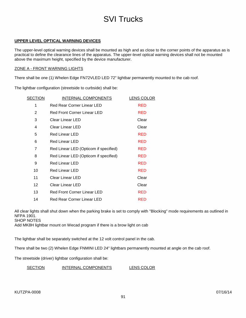
SVI Trucks
KUTZPA-0008 07/16/14
91
UPPER LEVEL OPTICAL WARNING DEVICES The upper-level optical warning devices shall be mounted as high and as close to the corner points of the apparatus as is practical to define the clearance lines of the apparatus. The upper-level optical warning devices shall not be mounted above the maximum height, specified by the device manufacturer. ZONE A - FRONT WARNING LIGHTS There shall be one (1) Whelen Edge FN72VLED LED 72" lightbar permanently mounted to the cab roof. The lightbar configuration (streetside to curbside) shall be:
SECTION INTERNAL COMPONENTS LENS COLOR
1 Red Rear Corner Linear LED RED
2 Red Front Corner Linear LED RED
3 Clear Linear LED Clear
4 Clear Linear LED Clear
5 Red Linear LED RED
6 Red Linear LED RED
7 Red Linear LED (Opticom if specified) RED
8 Red Linear LED (Opticom if specified) RED
9 Red Linear LED RED
10 Red Linear LED RED
11 Clear Linear LED Clear
12 Clear Linear LED Clear
13 Red Front Corner Linear LED RED
14 Red Rear Corner Linear LED RED
All clear lights shall shut down when the parking brake is set to comply with "Blocking" mode requirements as outlined in NFPA 1901. SHOP NOTES Add MK8H lightbar mount on Wecad program if there is a brow light on cab The lightbar shall be separately switched at the 12 volt control panel in the cab. There shall be two (2) Whelen Edge FNMINI LED 24" lightbars permanently mounted at angle on the cab roof. The streetside (driver) lightbar configuration shall be:
SECTION INTERNAL COMPONENTS LENS COLOR

SVI Trucks
KUTZPA-0008 07/16/14
92
1 Red Side Linear LED RED
2 Red Front Corner Linear LED RED
3 Red Linear LED RED
4 Red Front Corner Linear LED RED
The curbside (passenger) lightbar configuration shall be:
SECTION INTERNAL COMPONENTS LENS COLOR
1 Red Side Linear LED RED
2 Red Front Corner Linear LED RED
3 Red Linear LED RED
4 Red Front Corner Linear LED RED
All clear lights shall shut down when the parking brake is set to comply with "Blocking" mode requirements as outlined in NFPA 1901. The lightbar shall be separately switched at the 12 volt control panel in the cab. PRIORITY GREEN OPTICOM
One (1) Priority Green Opticom Microtube Extreme Range module shall be provided mounted inside the lightbar. The Opticom shall be activated with light bar and de-activated when the park brake is set and the vehicle is in blocking mode. ZONES B AND D - SIDE WARNING LIGHTS UPPER REAR CORNER WARNING LIGHTS There shall be two (2) Whelen 900 series (9" x 7") Red Linear Super-LED lights (90RR5FCR) provided, one (1) each side. Each light shall have a clear lens and chrome flange. The lights shall be switched at the 12 volt control panel in the cab. UPPER FORWARD CORNER WARNING LIGHTS There shall be two (2) Whelen 900 series (9" x 7") Red Linear Super-LED lights (90RR5FCR) provided, one (1) each side. Each light shall have a clear lens and chrome flange. The lights shall be switched at the 12 volt control panel in the cab. ZONE C - REAR WARNING LIGHTS There shall be two (2) Whelen 900 series (9" x 7") Red Linear Super-LED lights (90RR5FCR) provided, one (1) each side. Each light shall have a clear lens and chrome flange. The lights shall be switched at the 12 volt control panel in the cab.

SVI Trucks
KUTZPA-0008 07/16/14
93
LOWER LEVEL OPTICAL WARNING DEVICES To define the clearance lines of the apparatus, the optical center of the lower-level optical warning devices in the front of the vehicle shall be mounted on or forward of the front axle centerline and as close to the front corner points of the apparatus as is practical. The optical center of the lower-level optical warning devices at the rear of the vehicle shall be mounted on or behind the rear axle centerline and as close to the rear corners of the apparatus as is practical. The optical center of any lower-level device shall be between 18 in. and 62 in. (460 mm and 1600 mm) above level ground for large apparatus, and 18 in. and 48 in. (460 mm and 1220 mm) above level ground for small apparatus. A midship optical warning device shall be mounted right and the left sides of the apparatus if the distance between the front and rear lower-level optical devices exceeds 25 ft (7.6 m) at the optical center. Additional midship optical warning devices shall be required, where necessary, to maintain a horizontal distance between the centers of adjacent lower-level optical warning devices of 25 ft (7.6 m) or less. The optical center of any midship mounted optical warning device shall be between 18 in. and 62 in. (460 mm and 1600 mm) above level ground. ZONE A - FRONT WARNING LIGHTS The warning lights shall be supplied and installed by the cab/chassis manufacturer. They shall be Whelen lights to complete an NFPA compliant lower level warning light system. The lights shall be switched at the 12 volt control panel in the cab. ZONES B AND D - CAB INTERSECTOR LIGHT (CAB FRONT CORNERS) The warning lights shall be supplied and installed by the cab/chassis manufacturer. They shall be Whelen lights to complete an NFPA compliant lower level warning light system. The lights shall be switched at the 12 volt control panel in the cab. ZONES B AND D - CAB INTERSECTOR LIGHT (CAB SIDE) There shall be two (2) Whelen 600 series (6" x 4") red Linear Super-LED lights (60R02FCR) provided, one (1) each side. Each light shall have a clear lens and chrome flange. The lights shall be switched at the 12 volt control panel in the cab. ZONES B AND D - BODY INTERSECTOR LIGHT (BODY WHEELWELL AREA) There shall be two (2) Whelen 600 series (6" x 4") red Linear Super-LED lights (60R02FCR) provided, one (1) each side. Each light shall have a clear lens and chrome flange. The lights shall be switched at the 12 volt control panel in the cab. ZONES B AND D - BODY INTERSECTOR LIGHT (BODY REAR CORNERS) There shall be two (2) Whelen 500 series (5" x 2") red Linear Super-LED lights (50R02ZCR) provided, one (1) each side. Each light shall have a clear lens and chrome flange. The lights shall be switched at the 12 volt control panel in the cab.

SVI Trucks
KUTZPA-0008 07/16/14
94
ZONE C - REAR WARNING LIGHTS (LOWER REAR CORNERS) There shall be two (2) Whelen 600 series (6" x 4") red Linear Super-LED lights (60R02FCR) provided, one (1) each side. Each light shall have a clear lens and chrome flange. The lights shall be switched at the 12 volt control panel in the cab. LINE VOLTAGE ELECTRICAL SYSTEM ONAN PTO GENERATOR
The vehicle shall be equipped with an Onan Protec PTO generator system with a capacity of 30,000 watts at 120/240 VAC, 250/125 amps, single phase. Current frequency shall be stable at 60 hertz. The transmission’s PTO port and PTO, or the split shaft PTO, and all associated drive shaft components shall be rated to support the continuous duty torque requirements of the generator’s continuous duty rating as stated on the power source nameplate. Where the generator is driven by the chassis engine and transmission through a split shaft PTO, the driving compartment speedometer shall register when the generator drive system is engaged. Where the generator is driven by the chassis engine and transmission through a split shaft PTO and a chassis transmission retarder is furnished, it shall be automatically disengaged for generator operations. The direct drive generator shall be mounted so that it does not change the ramp breakover angle, angle of departure, or angle of approach as defined by other components, and it shall not extend into the ground clearance area. The direct drive generator shall be mounted away from exhaust and muffler areas or provided with a heat shield to reduce operating temperatures in the generator area. GENERATOR ENGAGEMENT A “Generator Engaged” indicator shall be provided in the driving compartment to indicate that the generator shift has been successfully completed. An “OK to Operate Generator” indicator shall be provided in the driving compartment to indicate that the generator is engaged (if not always engaged), the transmission is in the proper gear (if required, automatic transmissions only), and the parking brake is engaged (if applicable). An interlock system shall be provided to prevent advancement of the engine speed in the driving compartment or at any operator’s panel unless the parking brake is engaged, and the transmission is in neutral or the output of the transmission is correctly connected to a pump or generator instead of the drive wheels. WARRANTY PERIOD Provided such goods are operated and maintained in accordance with Onan's written instructions, Onan warrants that the Protec YDCR series PTO generators shall be free from defects in material and workmanship for a period of five (5) years or one thousand (1,000) hours, whichever comes first, from the date of delivery to the first purchaser.

SVI Trucks
KUTZPA-0008 07/16/14
95
GENERATOR SPLASH GUARD A powder coat painted splash cover shall be installed to reduce the amount of road spray on the frame mounted PTO generator. A V-ring seal shall also be installed in the cover to provide additional protection against contaminates reaching the generator front seals. GENERATOR MOUNTING
The generator shall be mounted between the chassis frame rails. The generator mounting brackets shall be fabricated using heavy duty steel tubing, or structural channel. The generator mounting shall be bolted and removable so that the generator can be lowered from under apparatus for service, if necessary. The generator case shall not extend below the bottom edge of the apparatus body. MANUALS AND SCHEMATICS
Two (2) complete manuals on parts list, maintenance, wiring schematics, hydraulic schematics, circuit boards, voltage regulator board and other components shall be provided on delivery. POWER-TAKE-OFF GENERATOR DRIVE
There shall be a "Hot Shift" power-take-off (PTO) installed on the transmission PTO opening of the chassis. The "Hot Shift" PTO is provided to allow the engagement of the PTO at higher engine RPM speeds. The PTO output shall be connected to the generator through hollow tube type driveline with heavy duty universals. The engagement of the PTO shall be in the chassis cab with a rocker switch and red pilot light to note engagement of the PTO or via the V-Mux screen if so equipped. The power supply to the PTO engagement control shall be wired to the parking brake and a neutral position transmission switch to prevent engagement unless the vehicle is stopped and transmission has been placed in neutral. The installation of the engine, transmission, driven accessories (power takeoffs (PTO), etc.) shall meet the engine and transmission manufacturers’ installation recommendations for the service intended. Model part number shall be Chelsea 277SGFJP-B5XV, 147% Ratio. ENGINE SPEED CONTROL An engine speed auxiliary control device (high idle switch or throttle) shall be installed to maintain a stable cycle output from generator when the apparatus is parked. An interlock shall prevent the operation of the engine speed auxiliary control device unless the parking brake is engaged and the transmission is in neutral or park, or the parking brake is engaged and the engine is disengaged from the drive wheels. The engine shall be prevented from regulating its own engine speed during times when engine rpm control is critical for consistent apparatus functions such as generator, water pump, or aerial operation.

SVI Trucks
KUTZPA-0008 07/16/14
96
LOADCENTER
The loadcenter shall be a Cutler Hammer, BR Series, specifically designed for protection and distribution of 120/240 volt AC, such as lighting and small motor branch circuits. The loadcenter enclosure shall be made of 16 gauge galvanized sheet steel. The galvanized coating provides corrosion protection and as such does not require paint. All trims used on the BR Loadcenter shall be chromate sealed and finished with electro disposition epoxy paint (ASA61) which exceeds requirements for outdoor and indoor applications. A combination surface/flush cover with integral door shall be supplied. The loadcenter shall be UL / CSA listed, NO EXCEPTIONS will be allowed. GENERATOR MONITORING PANEL
To properly monitor the generator performance and load demand during operation, the generator installation shall be equipped with a full instrument monitor panel.
Generator frequency in hertz Line 1 current in amperes Line 2 current in amperes Generator voltage in volts The program shall support the accumulation of elapsed generator hours. Generator hours shall be displayed. SHORE POWER INLET - BATTERY CHARGER Shore power shall be wired to all primary 120 VAC, 20 ampere electrical outlets on apparatus (maximum of two (2) circuits). Circuits shall be provided with circuit breaker protection with either generator or shore power providing power. OUTLETS AND CIRCUITS
The generator and or shore power shall supply the 120/240 volt electrical equipment and outlets outlined below. Proper circuit protection shall be installed as noted: Two (2) 120 volt exterior outlets, one (1) each side of front bumper.
The outlet receptacle(s) shall be 15 amp, twist-lock (NEMA L5-15R). Four (4) 120 volt exterior outlets, two (2) each side rear of body.
The outlet receptacle(s) on the rear of the body shall be 15 amp, twist-lock (NEMA L5-15R), two each side. LINE VOLTAGE ELECTRICAL SYSTEM GENERAL REQUIREMENTS Stability Any fixed line voltage power source producing alternating current (ac) shall produce electric power at 60 Hz, ±3 Hz when producing power at all levels between no load and full rated power. Any fixed line voltage power source shall produce electric power at the rated voltage ±10 percent when producing power at all levels between no load and full rated power.

SVI Trucks
KUTZPA-0008 07/16/14
97
The maximum voltage supplied to portable equipment shall not exceed 275 volts to ground. Higher voltage shall be permitted only when used to operate fixed wired, permanently mounted equipment on the apparatus. Conformance with National Electrical Code All components, equipment, and installation procedures shall conform to NFPA 70, National Electrical Code, except where superseded by the requirements of this chapter. Where the requirements of this chapter differ from those in NFPA 70, the requirements in this chapter shall apply. Where available, line voltage electrical system equipment and materials included on the apparatus shall be listed and used only in the manner for which they have been listed. All equipment and materials shall be installed in accordance with the manufacturer’s instructions. Location Ratings Any equipment used in a dry location shall be listed for dry locations. Any equipment used in a wet location shall be listed for wet locations. Any equipment, except a PTO-driven generator, used in an underbody or under chassis location that is subject to road spray shall be either listed as Type 4 or mounted in an enclosure that is listed as Type 4. If a PTO-driven generator is located in an underbody or under chassis location, the installation shall include a shield to prevent road spray from splashing directly on the generator. Grounding Grounding shall be in accordance with 250.34(A) and 250.34(B) of NFPA 70. Ungrounded systems shall not be used. Only stranded or braided copper conductors shall be used for grounding and bonding. The grounded current-carrying conductor (neutral) shall be insulated from the equipment-grounding conductors and from the equipment enclosures and other grounded parts. The neutral conductor shall be colored white or gray in accordance with 200.6, “Means of Identifying Grounded Conductors,” of NFPA 70. Any bonding screws, straps, or buses in the distribution panel board or in other system components between the neutral and equipment-grounding conductor shall be removed and discarded.

SVI Trucks
KUTZPA-0008 07/16/14
98
Bonding The neutral conductor of the power source shall be bonded to the vehicle frame. The neutral bonding connection shall occur only at the power source. In addition to the bonding required for the low voltage return current, each body and each driving or crew compartment enclosure shall be bonded to the vehicle frame by a copper conductor. The conductor shall have a minimum amperage rating, as defined in 310.15, “Ampacities for Conductors Rated 0–2000 Volts,” of NFPA 70, of 115 percent of the rated amperage on the power source specification label. A single conductor that is sized to meet the low voltage and line voltage requirements shall be permitted to be used. Ground Fault Circuit Interrupters In special service vehicles incorporating a lavatory, sink, toilet, shower, or tub, 120 V, 15 or 20 A receptacles within 6 ft (1.8 m) of these fixtures shall have ground fault circuit interrupter (GFCI) protection. GFCIs integrated into outlets or circuit breakers or as stand-alone devices shall be permitted to be used in situations. Power Source General Requirements All power source system mechanical and electrical components shall be sized to support the continuous duty nameplate rating of the power source. The power source shall be shielded from contamination that would prevent the power source from operating within its design specifications. Power Source Rating For power sources of 8 kW or larger, the power source manufacturer shall declare the continuous duty rating that the power source can provide when installed on fire apparatus according to the manufacturer’s instructions and run at 120°F (49°C) air intake temperature at 2000 ft (600 m) above sea level. The rating on the power source specification label shall not exceed the declared rating from the power source manufacturer. Access shall be provided to permit both routine maintenance and removal of the power source for major servicing. The power source shall be located such that neither it nor its mounting brackets interfere with the routine maintenance of the fire apparatus.

SVI Trucks
KUTZPA-0008 07/16/14
99
Instrumentation If the power source is rated at less than 3 kW, a “Power On” indicator shall be provided. If the power source is rated at 3 kW or more but less than 8 kW, a voltmeter shall be provided. If the power source is rated at 8 kW or more, the following instrumentation shall be provided at an operator’s panel:
Voltmeter 8) Current meters for each ungrounded leg 9) Frequency (Hz) meter 10) Power source hour meter The instrumentation shall be permanently mounted at an operator’s panel. The instruments shall be located in a plane facing the operator. Gauges, switches, or other instruments on this panel shall each have a label to indicate their function. The instruments and other line voltage equipment and controls shall be protected from mechanical damage and not obstructed by tool mounting or equipment storage. An instruction plate(s) that provides the operator with the essential power source operating instructions, including the power-up and power-down sequence, shall be permanently attached to the apparatus at any point where such operations can take place. Operation Provisions shall be made for placing the generator drive system in operation using controls and switches that are identified and within convenient reach of the operator. Where the generator is driven by the chassis engine and engine compression brakes or engine exhaust brakes are furnished, they shall be automatically disengaged for generator operations. Any control device used in the generator system power train between the engine and the generator shall be equipped with a means to prevent unintentional movement of the control device from its set position in the power generation mode. If there is permanent wiring on the apparatus that is designed to be connected to the power source, a power source specification label that is permanently attached to the apparatus at the operator’s control station shall provide the operator with the information required. The power source, at any load, shall not produce a noise level that exceeds 90 dBA in any driving compartment, crew compartment, or onboard command area with windows and doors closed or at any operator’s station on the apparatus. Power Supply Assembly The conductors used in the power supply assembly between the output terminals of the power source and the main over current protection device shall not exceed 12 ft (4 m) in length. All power supply assembly conductors, including neutral and grounding conductors, shall have an equivalent amperage rating and shall be sized to carry not less than 115 percent of the amperage of the nameplate current rating of the power source. If the power supply assembly connects to the vibrating part of a generator (not a connection on the base), the conductors shall be flexible cord or other fine-stranded conductors enclosed in metallic or nonmetallic liquid tight flexible conduit rated for wet locations and temperatures not less than 194°F (90°C).

SVI Trucks
KUTZPA-0008 07/16/14
100
Overcurrent Protection Manually resettable over current devices shall be installed to protect the line voltage electrical system components. Power Source Protection A main over current protection device shall be provided that is either incorporated in the power source or connected to the power source by a power supply assembly. The size of the main over current protection device shall not exceed 100 percent of the rated amperage stated on the power source specification label or the rating of the next larger available size over current protection device, where so recommended by the power source manufacturer. If the main over current protection device is subject to road spray, the unit shall be housed in a Type 4–rated enclosure. Branch Circuit Overcurrent Protection Over current protection devices shall be provided for each individual circuit and shall be sized at not less than 15 amps in accordance with 240.4, “Protection of Conductors,” of NFPA 70. Any panel board shall have a main breaker where the panel has six or more individual branch circuits or the power source is rated 8 kW or larger. Each over current protection device shall be marked with a label to identify the function of the circuit it protects. Dedicated circuits shall be provided for any large appliance or device (air conditioning units, large motors, etc.) that requires 60 percent or more of the rated capacity of the circuit to which it is connected, and that circuit shall serve no other purpose. Panelboards All fixed power sources shall be hardwired to a permanently mounted panel board unless one of the following conditions exists: 11) All line voltage power connections are made through receptacles on the power source and the receptacles are
protected by integrated over current devices. 1) Only one circuit is hardwired to the power source, which is protected by an integrated over current device. The panel shall be visible and located so that there is unimpeded access to the panel board controls. All panel boards shall be designed for use in their intended location. The panel(s) shall be protected from mechanical damage, tool mounting, and equipment storage. Where the power source is 120/240 V and 120 V loads are connected, the apparatus manufacturer or line voltage system installer shall consider load balancing to the extent that it is possible.

SVI Trucks
KUTZPA-0008 07/16/14
101
Wiring Methods Fixed wiring systems shall be limited to the following: 2) Metallic or nonmetallic liquid tight flexible conduit rated at temperatures not less than 194°F (90°C) with stranded
copper wire rated for wet locations and temperatures not less than 194°F (90°C) 1) Type SOW, SOOW, SEOW, or SEOOW flexible cord rated at 600 V and at temperatures not less than 194°F (90°C) Electrical cord or conduit shall not be attached to chassis suspension components, water or fuel lines, air or air brake lines, fire pump piping, hydraulic lines, exhaust system components, or low voltage wiring and shall be arranged as follows: 2) Separated by a minimum distance of 12 in. (300 mm) from exhaust piping or shielded from such piping 1) Separated from fuel lines by a minimum distance of 6 in. (150 mm) A means shall be provided to allow “flexing” between the driving and crew compartment, the body, and other areas or equipment whose movement would stress the wiring. Electrical cord or conduit shall be supported within 6 in. (150 mm) of any junction box and at a minimum of every 24 in. (600 mm) of run. Supports shall be made of nonmetallic materials or of corrosion-resistant or corrosion-protected metal. All supports shall be of a design that does not cut or abrade the conduit or cord and shall be mechanically fastened to the apparatus. Only fittings and components listed for the type of cord or conduit being installed shall be used. Splices shall be made only in a listed junction box. Additional Requirements for Flexible Cord Installations Where flexible cord is used in any location where it could be damaged, it shall be protected by installation in conduit, enclosures, or guards. Where flexible cord penetrates a metal surface, rubber or plastic grommets or bushings shall be installed. Wiring Identification Each line voltage circuit originating from the main panel board shall be identified. The wire or circuit identification either shall reference a wiring diagram or wire list or shall indicate the final termination point of the circuit. Where pre-wiring for future power sources or devices exists, the un-terminated ends shall be marked with a label showing their wire size and intended function.

SVI Trucks
KUTZPA-0008 07/16/14
102
Wiring System Components Only stranded copper conductors with an insulation rated for temperatures of at least 194°F (90°C) and wet locations shall be used. Conductors in flexible cord shall be sized in accordance with Table 400.5(A) of NFPA 70. Conductors used in conduit shall be sized in accordance with 310.15, “Ampacities for Conductors Rated 0–2000 Volts,” of NFPA 70. Aluminum or copper-clad aluminum conductors shall not be used. All boxes shall conform to and be mounted in accordance with Article 314, “Outlet, Device, Pull, and Junction Boxes; Conduit Bodies; Fittings; and Manholes,” of NFPA 70. All boxes shall be accessible using ordinary hand tools. Boxes shall not be permitted behind welded or pop-riveted panels. The maximum number of conductors permitted in any box shall be in accordance with 314.16, “Number of Conductors in Outlet, Device, and Junction Boxes, and Conduit Bodies,” of NFPA 70. All wiring connections and terminations shall provide a positive mechanical and electrical connection. Connectors shall be installed in accordance with the manufacturer’s instructions. Wire nuts or insulation displacement and insulation piercing connectors shall not be used. Each switch shall indicate the position of its contact points (i.e., open or closed) and shall be rated for the continuous operation of the load being controlled. All switches shall be marked with a label indicating the function of the switch. Circuit breakers used as switches shall be “switch rated” (SWD) or better. Switches shall simultaneously open all associated line voltage conductors. Switching of the neutral conductor alone shall not be permitted. Line voltage circuits controlled by low voltage circuits shall be wired through properly rated relays in listed enclosures that control all non-grounded current-carrying conductors. Receptacles and Inlet Devices Wet and Dry Locations All wet location receptacle outlets and inlet devices, including those on hardwired, remote power distribution boxes, shall be of the grounding type, provided with a wet location cover, and installed in accordance with Section 406.8, “Receptacles in Damp or Wet Locations,” of NFPA 70. All receptacles located in a wet location shall be not less than 24 in. (600 mm) from the ground. Receptacles on off road fire apparatus shall be a minimum of 30 in. (750 mm) from the ground. All receptacles located in a dry location shall be of the grounding type and shall be at least 12 in. (300 mm) above the interior floor height. No receptacle shall be installed in a face-up position. The face of any wet location receptacle shall be installed in a plane from vertical to not more than 45 degrees off vertical. Receptacle Label Each receptacle shall be marked with a label indicating the nominal line voltage (120 volts or 240 volts) and the current rating in amps of the circuit. If the receptacle is DC or other than single phase, that information shall also be marked on the label. All receptacles and electrical inlet devices shall be listed to UL 498, Standard for Safety Attachment Plugs and Receptacles, or other recognized performance standards. Receptacles used for DC voltages shall be rated for DC service.

SVI Trucks
KUTZPA-0008 07/16/14
103
Wiring Schematics An "As-Built" Wiring diagrams for line voltage systems shall be provided to include the following information; 2) Pictorial representations of circuit logic for all electrical components and wiring (c) Circuit identification (d) Connector pin identification (e) Zone location of electrical components (f) Safety interlocks (g) Alternator–battery power distribution circuits (h) Input/output assignment sheets or equivalent circuit logic implemented in multiplexing systems 120/240 VAC SCENE LIGHTING REAR TRIPOD SCENE LIGHTS Two (2) Fire Research Focus; model FCA656-S75, tripod telescopic light shall be provided. The light pole shall be anodized aluminum and have a knurled twist lock mechanism to secure the extension pole in position. The extension pole shall extend 28" and rotate 360 degrees. An internal brake shall slow the extension pole during lowering. The outer pole shall be a grooved aluminum extrusion. The folding legs shall be anodized aluminum tubing with plastic endcaps. The fully extended tripod system shall exceed a height of 8' and be less than 5' when collapsed. Wiring shall extend from the pole bottom with a 4' retractile cord. The lamphead shall have one (1) quartz halogen 750 watt 120 volt bulb. The bulb shall draw 6.3 amps and generate 19,600 lumens. The bulb shall be accessible through the front. The lamphead shall direct 50 percent of the light onto the action area while providing 50 percent to illuminate the working area. The lamphead angle of elevation shall be adjustable at a pivot in the mounting arm and the position locked with a round knurled locking knob. The lamphead shall incorporate heat-dissipating fins and be no more than 5" deep by 3 3/8" high by 10" wide. Scene lights shall be provided with a lens or a means for preventing damage from water spray and shall be listed for wet location usage. A weatherproof on-off toggle switch shall be mounted in a switchbox below the lamphead. A wire guard shall be furnished to protect the lamphead glass. A tripod truck mount bracket set shall be provided for each light. Each set shall include a lower base plate, an upper lock with a quick release spring loaded locking pin, and a shim set. SHOP NOTES Make:Fire Research Model: Focus P/N: FCA656-S75-ON-6F3 Mirrored stainless steel body protection panels shall be proviced behind each tri-pod light head. LIGHT TOWER One (1) Command Light, CL Series light tower(s) shall be provided and installed on the completed unit. A flashing warning light shall be provided in cab, indicating when a light tower is not in nested position as required by NFPA 1901. The Command Light shall be covered by a five (5) year limited warranty from defects in materials and workmanship. An operation, maintenance, and parts manual shall be provided with the completed unit.

SVI Trucks
KUTZPA-0008 07/16/14
104
The light tower shall extend 131" above the mounting surface and shall extend to full upright position in less than 15 seconds. The overall size of nested light tower shall be approximately 42" wide x 74" long x 12" high and weigh approximately 300 pounds. Light Tower Construction and Design The Command Light assembly shall be of aluminum construction, with stainless steel shafts and bronze bushings for long life and low maintenance. The electrically controlled unit shall not require usage of the vehicle's air supply for operation, thereby eliminating the chance for air leaks in the vehicle braking system. Hydraulic or pneumatic type floodlights are not acceptable alternatives to the specified all electric light tower. The light tower shall be tested to in wind conditions of 90 mph (150 kph) minimum. Light towers that have not been tested to these conditions are not acceptable. The light tower shall be capable of overhanging the side or back of the vehicle to provide maximum illumination to the vicinity adjacent to the vehicle for the safety of emergency personnel in high traffic conditions. Light towers that are only capable of rotation at the top of a pole are not acceptable to the specified light tower. Light Tower Electrical System The light tower shall be a two-stage articulating device with a lighting bank on top of the second stage capable of continuous 360 degree rotation. The light shall be elevated by electric linear actuators, one (1) actuator shall elevate the light bank and one (1) actuator shall adjust the light bank angle from 0 to 110 degrees. Power for the light bank shall be supplied through power collecting rings thus allowing continuous 360 degree rotation in either direction. The tower base shall have a light that illuminates the envelope of motion during any movement of the light tower mast as required by NFPA 1901. Light Tower Floodlights The Command Light model CL602A shall be equipped with the following bank of floodlights: Floodlight manufacturer: Fire Research Number of lamp heads: Six (6) Spectra LED Voltage: 120 volts Watts of each lamp head: 150 watt Total watts of light tower: 900 watts Total lumens of light tower: 90,000 lumens Configuration: The light heads shall be mounted with three (3) on each side of
the light tower, giving two (2) vertical lines of three (3) when the lights are in the upright position.
Light Tower Backlight Option A backlight option shall be provided on the light tower. The lower pair of light heads shall be capable of being rotated about a horizontal axis 180 degree, providing light down on the vehicle or to the opposite side of the vehicle while allowing the fixed lights to remain pointed at the scene. The hand-held remote control shall have an additional switch supplied for the backlight rotation option.
SVI Trucks
KUTZPA-0008 07/16/14
105
Light Tower Paint The light tower shall be electrostatically powder coated with a hammer tone gray color. Light Tower Controls The light tower(s) shall be operated with a hand-held 15-foot umbilical line remote control. The storage station for the remote control unit shall be equipped with a button to activate the "Auto-Park" automatic nesting feature. The remote control shall be located per the itemized compartment list and include; Three (3) switches; one (1) for each pair of lights. One (1) switch for light bank rotation. One (1) switch for elevating lower stage. One (1) switch for elevating upper stage. One (1) switch for optional light bank rotation. One (1) switch for the optional strobe. One (1) indicator light to indicate when light bank is out of the roof nesting position. One (1) indicator light to indicate when light bank is rotated to proper nesting position. Light Tower Mounting The specified light tower(s) shall be recessed into the roof of body to allow light tower(s) to be stowed below roof level. The floor and side walls of recessed area shall be fabricated as a separate module from 3/16" aluminum treadplate with an overlapping 3" flange around perimeter roof line. The recessed area shall be completely water tight. All electrical connections made to light tower shall be located on sidewalls for a water tight connection. The recessed area shall have two (2) water drain holes (in opposite corners) with flexible 1" diameter hose routed to the area below the body. EQUIPMENT PAYLOAD WEIGHT ALLOWANCE In compliance with NFPA 1901 standards, the special service vehicle shall be designed for an equipment loading allowance of 8,000 lbs. of Kutztown Fire Company provided equipment based on a 50,001 - 60,000 pound gross vehicle weight rating. EQUIPMENT The following equipment shall be furnished with the completed special service vehicle; (i) One (1) container of assorted stainless steel nuts, bolts, screws and washers used in the construction of the
apparatus shall be provided with the completed apparatus.
There shall be two (2) Zico SAC-44-E NFPA approved folding aluminum wheel chocks provided for 44" diameter tires that together will hold the vehicle when loaded to its GVWR or GCWR, on a hard surface with a 20 % grade, with the transmission in neutral, and the parking brake released.
The wheel chock(s) shall be mounted behind rear wheels, below body on streetside.
Two (2) Streamlight FireBox halogen flashlight(s) shall be provided. Each flashlight shall be orange in color and have a 12 volt DC charger and vehicle mount kit. Each flashlight shall have a 8 watt halogen spotlight style bulb and reflector with 2 ultra-bright LED taillights. The flashlight(s) shall be wired to battery direct unless otherwise specified by Kutztown Fire Company.

SVI Trucks
KUTZPA-0008 07/16/14
106
The flashlight(s) shall be mounted on the completed unit in cab.
SVI to install customer supplied air shore struts and rescue struts onto the toolboards located in compartments C4 and S4. REMAINING NFPA MINOR EQUIPMENT BY PURCHASER All other minor equipment not specified above, but required by NFPA 1901, section 10.5.1 shall be supplied and mounted by Kutztown Fire Company before the unit is placed in emergency service.


