
Kushilov Chowdhury
10
Industrial Application & Maintenance Procedures of Optical Fibres Kushilov Chowdhury M. Tech (Avionics) Amity Institute of Space Science & Technology Amity University
-
Upload
noida-amity-university-uttar-pradesh -
Category
Documents
-
view
252 -
download
5
Transcript of Kushilov Chowdhury

Industrial Application&
Maintenance Proceduresof
Optical Fibres
Kushilov Chowdhury
M. Tech (Avionics)
Amity Institute of Space Science & Technology
Amity University

Telecom Equipment And FamiliarizationSMPS (Switched Mode Power Supply)
• Converts 3-Ph A.C. input power supply to D.C. by virtue of programmable rectifiers present in it.• Charges the battery Van which in turn provides the power supply for all the other telecom equipments.
Suppliers of SMPS for Power-Grid: Huawei, AmaraRaja
Battery Van:• Charged by D.C. Power Supply from SMPS• Generates a -48V voltage supply (standard voltage supply for telecom Equipments)
Suppliers: Amara Raja
System Rack: • Contains the Fiber Optic Distribution Panel (FODP)
Suppliers: SER & M, Tellabs, HCL,ZTE.
System Rack Battery Van
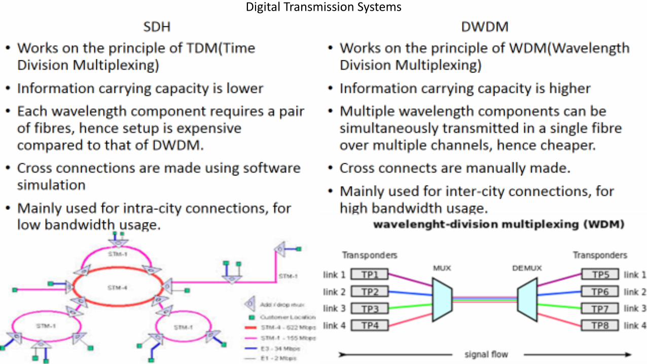
Digital Transmission Systems

Fibre ManagementPrinciple :
• Optic Fibre is a transparent fiber made of high quality extruded glass (silica) or plastic.
• Can function as a waveguide, or “light pipe”, to transmit light between the two ends of the fiber.
• Works on the principle of Total Internal Reflection.
• Photons, the units of optical energy are used to transmit, store and process information.
• Power over Fiber (PoF) optic cables can also work to deliver an electric current for low-power electric devices.

The broad two types of optical fibres are:
Single Mode Fiber
1. Supports only one stable mode of propagation.2. Typical Core Diameter:8.3 micron3. Lower attenuation4. Lower Dispersion5. Longer reach with high data rate transmission(greater
than 50km with STM-4)6. Expensive(LASER is used)7. Used in telecom CATV at 1310 and1550 nm
Multi Mode Fiber
1. Supports more than one stable mode of propagation. 2. Typical Core Diameters: 62.5micron & 50 micron3. Higher attenuation4. Higher Dispersion5. Shorter reach with high data rate transmission(less than
0.5km with STM-4)6. Cheaper(LED is used)7. Used in LAN under 2km at 850 and 1300 nm.

Types of Fibre Connectors

Advantages of Optic Fibre Technology:
• Extremely high Bandwidth ie high information carrying capacity
• Very low attenuation(0.02db/km), no cross talk and disturbances
• Low Cost as compared to copper
• Immune to EMI(Electromagnetic interference) and RFI(radiofrequency interference)
• Dielectric in nature, so not susceptible to electrical surroundings
• Small size, light weight, easy to install and difficult to tap (hence secure)
Technology deployed:
• UGOFC(Under-Ground Optic Fibre Cable) - has been provided to create PoP (Point of Presence) where sub-station or overhead line is not available.
• OPGW(Optical Fibre Ground Wire ) - Over-Head high voltage Transmission line.
Steps for Installation of Optical Fibers:• Investigation of the soil before using trenching techniques
• Methods for inspecting and repairing underground plastic ducts
• Fast mapping of underground Networks
• Low Environmental impact trenching technique:• Horizontal Directional Drilling
• Mini-trench installation technique
• Micro-trench installation technique

Trouble-shooting and MaintenanceOTDR (Optical Time Domain Reflectometer) :
• Optoelectronic instrument used to characterize an optic fiber. It is the optical equivalent of an electronic time domain Reflectometer.
• Injects a series of optical pulses into the fiber under test.
• Extracts, from the same end of the fiber, light that is scattered (Rayleigh backscatter) or reflected back from points along the fibre.
• The strength of the return pulses is measured and integrated as a function of time, and plotted as a function of fiber length.
Application :
• Provides us the distance of line-fault from a given end.
OPM(Optical Power Meter)
• Used to measure the power in optical signal. Measures average power in fiber optic systems.
• Consists of a calibrated sensor, measuring amplifier and display. The sensor primarily consists of a photodiode selected for the appropriate range of wavelengths and power levels.
• Power is expressed in dB measured wrt 1mW power(0dB)
• Sensors are semiconductor materials like Silicon, Germanium, GaAs, etc. each having a specific operating wavelength range.[E.g.: GaAs sensors are mostly used for single-mode fiber testing at 1270 - 1650 nm.

Splicing: [Process of jointing optical fibres with each other]
• Done by controlled melting of optical fibres resulting in softening of glass after which fibres are fed together
• Uses heat created from an electrical arc
• Melting Point: around 1600-2000`C
Network Management System(NMS)• Real time monitoring of the telecom network through state of
the art National Telecom Control Centre at Delhi• Fault Management in a 24x7 basis• Customer support HELPDESK• Technical support• Dedicated and focused approach on RTCC’s at Kolkata, Delhi,
Mumbai & Bengaluru.

Thank You!!!!