Kurt Lesker CMS-18 Multi Target Sputter Deposition SOPKurt Lesker CMS-18 Multi Target Sputter...
17
NRF Kurt Lesker CMS-18 SOP Revision 23 8/21/2019 Page 1 of 17 Kurt Lesker CMS-18 Multi Target Sputter Deposition SOP NOTE: Latest revisions are in Blue. Table of Contents 1.0 Safety 2.0 Quality Control and Calibrations 3.0 Pre-Operation 4.0 Problem Recovery 5.0 Sample Load 6.0 Sputter Types and Materials 7.0 Running a Deposition 8.0 Sample Unload
Transcript of Kurt Lesker CMS-18 Multi Target Sputter Deposition SOPKurt Lesker CMS-18 Multi Target Sputter...
NRF Kurt Lesker CMS-18 SOP Revision 23 8/21/2019
Page 1 of 17
Kurt Lesker CMS-18 Multi Target Sputter Deposition
SOP
NOTE: Latest revisions are in Blue.
Table of Contents
1.0 Safety 2.0 Quality Control and Calibrations 3.0 Pre-Operation 4.0 Problem Recovery 5.0 Sample Load 6.0 Sputter Types and Materials 7.0 Running a Deposition 8.0 Sample Unload
NRF Kurt Lesker CMS-18 SOP Revision 23 8/21/2019
Page 2 of 17
1.0 Safety
1.1 High Voltage - High Voltage Radio Frequency and High Voltage DC is used throughout the system. System maintenance may only be performed NRF Staff. Do not remove any tool covers or defeat any interlock on this system.
1.2 Moving Components - The User should be aware at all times of the moving components associated with this tool. For instance, the turret unit does rotate and does present a potential hazard. The User must exert caution at all times such that a limb, finger, or article of clothing does not become trapped or entangled (or worse, violently detached) when components of the machine are in motion.
1.3 Heat – The sample platen is heated and should never be touched. 1.4 Buddy System – the Buddy System is not needed for after hours usage
of this equipment
2.0 Quality Control and Calibrations
2.1 Sputter Rates
2.1.1. The Sputter rates contained in the spreadsheet located on the sputter tool computer were accurate at the time of calibration and should only be used as an estimate. Rate calibrations are not performed on a periodic schedule. Due to the complexity of the sputter process, these rates may change slightly over time. If you need a very specific film thickness you must run a test sample.
Use the following method: Use clean polished silicon or glass for the test. Run recipe long enough to obtain a film thickness of at least 1500 angstroms. Do not cover your sample with a shadow mask or tape. Place one droplet of photoresist on the test sample film using a pipette and hotplate bake the sample for 2 mins. at 112C.. Small bottles of photoresist are located on the bottom shelf of the Litho Bay chrome rack. Etch the film using the appropriate wet etchant or plasma etch. Remove the photoresist using acetone after etch and measure the film etch step using the Dektak 150 Profiler. Once you have the calibrated rate, email the results to NRF Staff. You may request that your target be loaded into the same sputter gun in the future for consistency.
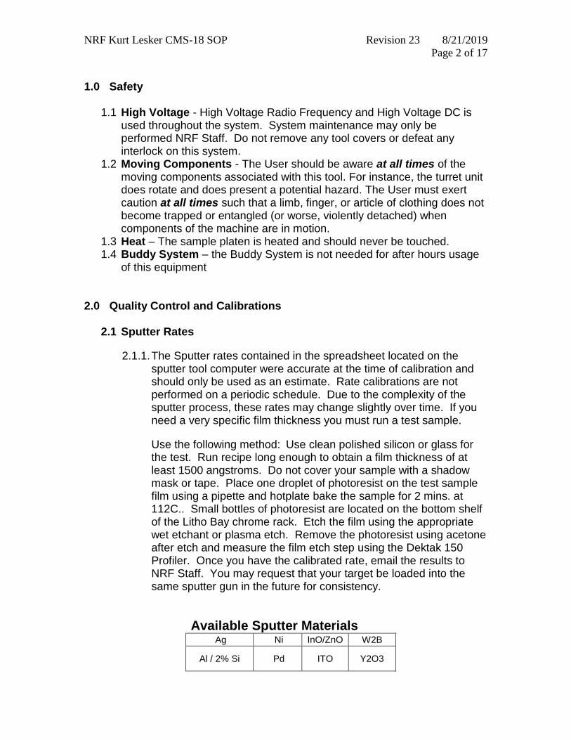
Available Sputter Materials
Ag Ni InO/ZnO W2B
Al / 2% Si Pd ITO Y2O3
NRF Kurt Lesker CMS-18 SOP Revision 23 8/21/2019
Page 3 of 17
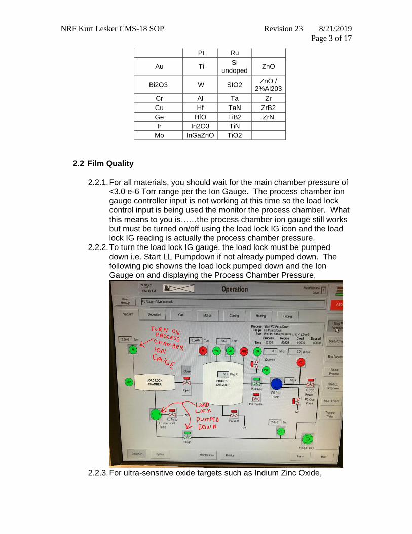
Pt Ru
Au Ti Si
undoped ZnO
Bi2O3 W SIO2 ZnO /
2%Al203
Cr Al Ta Zr
Cu Hf TaN ZrB2
Ge HfO TiB2 ZrN
Ir In2O3 TiN
Mo InGaZnO TiO2
2.2 Film Quality 2.2.1. For all materials, you should wait for the main chamber pressure of
<3.0 e-6 Torr range per the Ion Gauge. The process chamber ion gauge controller input is not working at this time so the load lock control input is being used the monitor the process chamber. What this means to you is……the process chamber ion gauge still works but must be turned on/off using the load lock IG icon and the load lock IG reading is actually the process chamber pressure.
2.2.2. To turn the load lock IG gauge, the load lock must be pumped down i.e. Start LL Pumpdown if not already pumped down. The following pic showns the load lock pumped down and the Ion Gauge on and displaying the Process Chamber Pressure.
2.2.3. For ultra-sensitive oxide targets such as Indium Zinc Oxide,
NRF Kurt Lesker CMS-18 SOP Revision 23 8/21/2019
Page 4 of 17
InGaZnO, the main chamber base pressure must be <5.0e -7 Torr. This is also true for reactive oxide recipes. The best way to achieve this is to request that the target be loaded at the end of the day and reserve the tool for the next morning. This can be done via email to Staff in most cases.
2.3 Heater Box Temperature
2.3.1. The temperature of the heater box is controlled by 2 thermocouple sensors located several inches from the sample holder. There is a substantial temperature offset between the system readout and actual sample temperature. Please check the calibration curves posted and consult with the process engineers for elevated temperature processes.
3.0 Pre-Operation
3.1 Please read and observe reservation requirements on the RSC Kurt Lesker Sputter equipment page.
3.2 When NRF Staff changes the sputter targets, a note regarding loaded targets will appear in the logoff notes. To see the note, go to the sputter equipment page and click on “Status Log”. The sputter materials loaded will be listed in order guns 1-4. The time stamp of the note will also give you an idea of when the chamber pump down started.
3.3 Log onto the tool via the Tumi. 3.4 On the machine, use the Deposition screen (click the Deposition tab
along the top of the screen) to verify that the targets you need are listed and match the Staff logoff notes. If not, log off the TUMI with a comment/email to Staff stating the problem and Call NRF Staff.
4.0 Problem Recovery 4.1 NEED TO STOP SYSTEM OR ABORT. Note: Do not use this abort
sequence if you are in the middle of a “ramp” recipe (i.e. insulating target material) and plasma is ON, you will damage the target. If you need to stop the system during any procedure other than running a process recipe with “ramp” in the name, perform the following steps:
On the Vacuum screen…click the red “Abort” icon below 2 times. It will turn maroon and then back to red.
Verify the Loadlock door is closed. Click “Start PC Pumpdown”. Wait for the recipe to display “Stop Recipe” in the recipe window Step field.
If the “Start PC Pumpdown” routine does not run (see the process recipe window for status) and the system has been aborted using the Abort button, turn the LL Turbo Pump off by clicking once on the LL Turbo Pump icon on the vacuum screen, see below. Make
NRF Kurt Lesker CMS-18 SOP Revision 23 8/21/2019
Page 5 of 17
sure it is “RED” as shown below. Log off the machine at this point and make a TUMI comment….someting is broken.
4.2 NO PLASMA. If there is no plasma during process recipe execution, perform the abort sequence (2.1 above) and then run the recipe one more time. If the plasma still fails to ignite, contact NRF Staff during regular school hours. If after hours, put a note on the machine, email Staff and log a comment in the TUMI system when logging off.
4.3 LOST SAMPLE…SOMETING BROKE. If the sample falls from the load arm or something breaks, contact NRF Staff during regular school hours. If after hours, put a note on the machine, email Staff and log a comment in the TUMI system when logging off.
5.0 Operation - Sample Load
5.1 If you would like to check the Process Chamber base pressure before you start. Do the following (if not, proceed to step 5.2):
5.1.1. The process chamber ion gauge controller input is not working at this time
so the load lock control input is being used the monitor the process chamber.
What this means to you is……the process chamber ion gauge still works but
must be turned on/off using the load lock IG icon. To turn ON the load lock
IG gauge, the load lock must be pumped down. If it is not, press Start LL
Pumpdown and wait for the recipe to end. Then press the IG icon on the
load lock and it will turn green. Wait about 1 min for the correct pressure to
be displayed above the icon. This is the “Process Chamber” pressure. The
following pic shows the load lock pumped down and the Ion Gauge on and
displaying the Process Chamber Pressure.
NRF Kurt Lesker CMS-18 SOP Revision 23 8/21/2019
Page 6 of 17
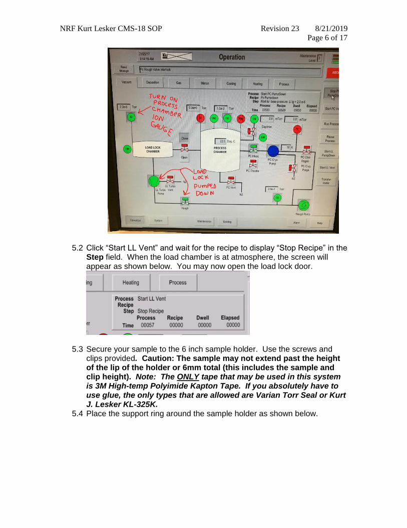
5.2 Click “Start LL Vent” and wait for the recipe to display “Stop Recipe” in the Step field. When the load chamber is at atmosphere, the screen will appear as shown below. You may now open the load lock door.
5.3 Secure your sample to the 6 inch sample holder. Use the screws and clips provided. Caution: The sample may not extend past the height of the lip of the holder or 6mm total (this includes the sample and clip height). Note: The ONLY tape that may be used in this system is 3M High-temp Polyimide Kapton Tape. If you absolutely have to use glue, the only types that are allowed are Varian Torr Seal or Kurt J. Lesker KL-325K.
5.4 Place the support ring around the sample holder as shown below.
NRF Kurt Lesker CMS-18 SOP Revision 23 8/21/2019
Page 7 of 17
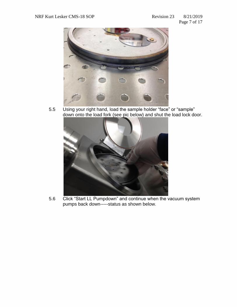
5.5 Using your right hand, load the sample holder “face” or “sample”
down onto the load fork (see pic below) and shut the load lock door.
5.6 Click “Start LL Pumpdown” and continue when the vacuum system
pumps back down-----status as shown below.
NRF Kurt Lesker CMS-18 SOP Revision 23 8/21/2019
Page 8 of 17
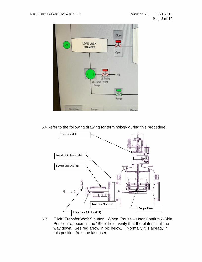
5.6 Refer to the following drawing for terminology during this procedure.
5.7 Click “Transfer Wafer” button. When “Pause – User Confirm Z-Shift
Position” appears in the “Step” field, verify that the platen is all the way down. See red arrow in pic below. Normally it is already in this position from the last user.
NRF Kurt Lesker CMS-18 SOP Revision 23 8/21/2019
Page 9 of 17
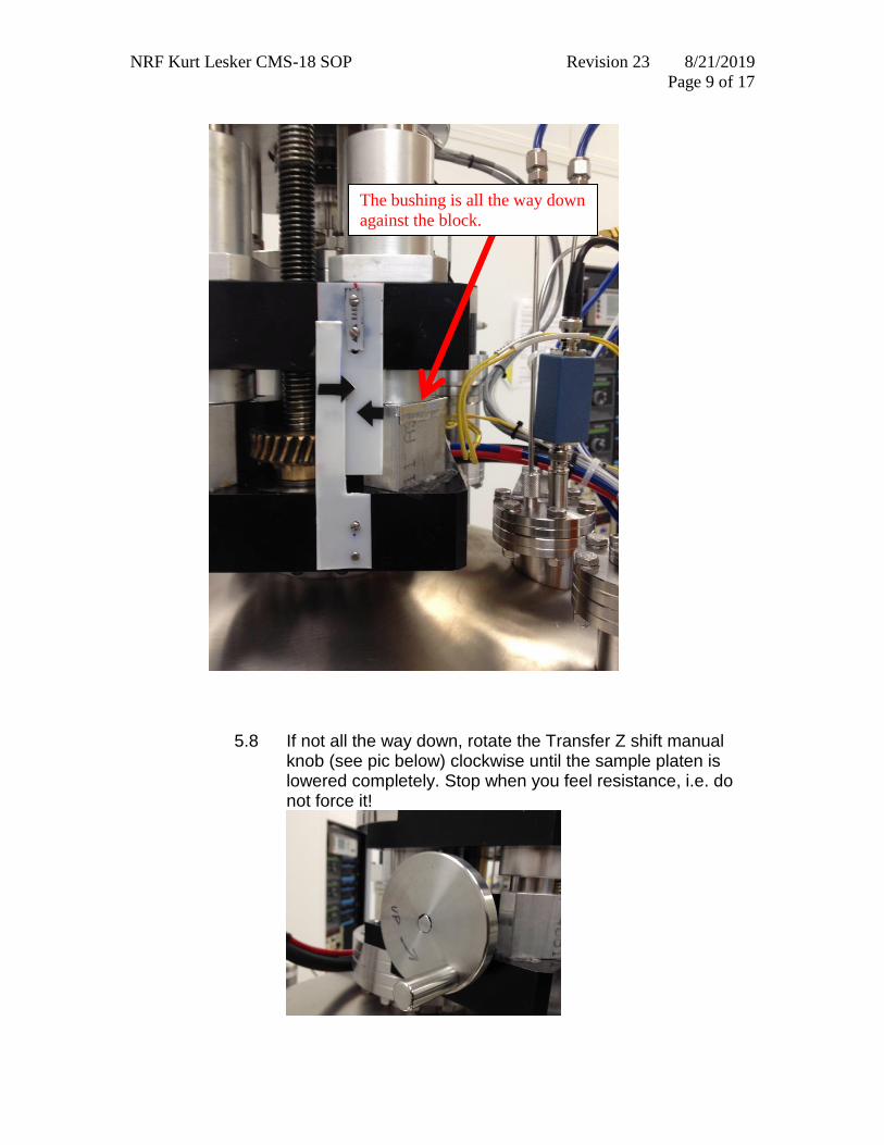
5.8 If not all the way down, rotate the Transfer Z shift manual
knob (see pic below) clockwise until the sample platen is lowered completely. Stop when you feel resistance, i.e. do not force it!
The bushing is all the way down
against the block.
NRF Kurt Lesker CMS-18 SOP Revision 23 8/21/2019
Page 10 of 17
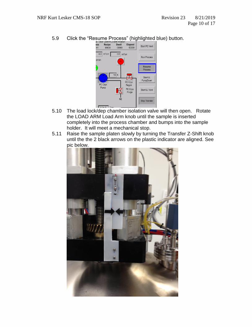
5.9 Click the “Resume Process” (highlighted blue) button.
5.10 The load lock/dep chamber isolation valve will then open. Rotate
the LOAD ARM Load Arm knob until the sample is inserted completely into the process chamber and bumps into the sample holder. It will meet a mechanical stop.
5.11 Raise the sample platen slowly by turning the Transfer Z-Shift knob until the the 2 black arrows on the plastic indicator are aligned. See pic below.
NRF Kurt Lesker CMS-18 SOP Revision 23 8/21/2019
Page 11 of 17
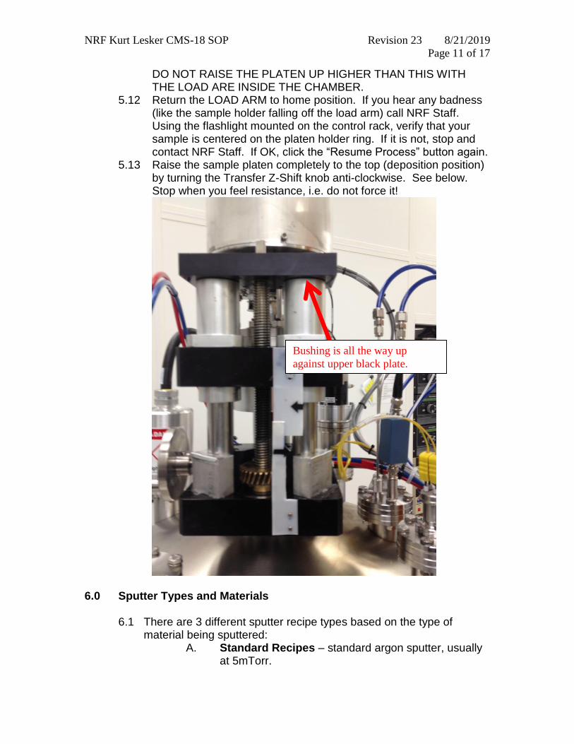
DO NOT RAISE THE PLATEN UP HIGHER THAN THIS WITH THE LOAD ARE INSIDE THE CHAMBER.
5.12 Return the LOAD ARM to home position. If you hear any badness (like the sample holder falling off the load arm) call NRF Staff. Using the flashlight mounted on the control rack, verify that your sample is centered on the platen holder ring. If it is not, stop and contact NRF Staff. If OK, click the “Resume Process” button again.
5.13 Raise the sample platen completely to the top (deposition position) by turning the Transfer Z-Shift knob anti-clockwise. See below. Stop when you feel resistance, i.e. do not force it!
6.0 Sputter Types and Materials
6.1 There are 3 different sputter recipe types based on the type of material being sputtered:
A. Standard Recipes – standard argon sputter, usually at 5mTorr.
Bushing is all the way up
against upper black plate.
NRF Kurt Lesker CMS-18 SOP Revision 23 8/21/2019
Page 12 of 17
B. Special Material Recipes – argon sputter (sometimes includes other gases)of insulating materials. Usually done in RF guns 1 or 3. Insulating materials have poor thermal conductivity and crack easily. Because of this, magnetron power must be increased and decreased slowly to prevent target damage. These recipes typically take approximately 6 minutes to ramp power both up and down. Please allow an additional 15 mins for your sputter reservation. Discuss your process with NRF Staff before running these materials.
Special Materials Include:
C. Reactive Recipes – reactive gases are added to the chamber to reactively create films. Example: O2 is added to chamber while sputtering Chromium to create Chromium Oxide. Be sure to reserve the appropriate target for these recipes, i.e. for Reactive AL2O3 you would reserve the “Aluminum” target, not AL2O3.
7.0 Running a Deposition Process
7.1 Open the Excel Kurt Lesker Log workbook on the sputter tool
desktop. You will need to use the “windows” button on the keyboard. The spreadsheet is located on top of the windows start menu if not already open. Use the “recipes” spreadsheet to determine what recipe you need to use and to determine your sputter time. See the example table below. Find:
a. your target, column A b. the gun in which the target is loaded, column B c. use the recipe name, column C d. use the Dep Rate A/second in column D to calculate sputter
time
Ge HfO ITO TiB2 YSZ ZrB2
In2O3 Si -
undoped TiN ZnO ZrN
Bi2O3 InGaZnO SIO2 TiO2 Y2O3 ZnO-Al203
Hf InO/ZnO TaN W2B
NRF Kurt Lesker CMS-18 SOP Revision 23 8/21/2019
Page 13 of 17
Kurt Lesker Sputter Recipe Table
Target Gun
Recipe Name
naming convention is: gun_power_pressure MT
Dep Rate A/second
Ag 2 G2_250_5 xx
Ag 4 G4_250_5 xx
Al 1 G1_350_5 xx
Al 1 G1_500_5 xx
Al 3 G3_500_5 xx
Al 3 G3_350_5 xx
Au 2 G2_150_5 xx
Au 4 G4_150_5 xx
Cr 2 G2_250_5 xx
Cr 4 G4_250_5 xx
Cu 1 G1_350_5 xx
Cu 2 G2_250_5 xx
Example Table
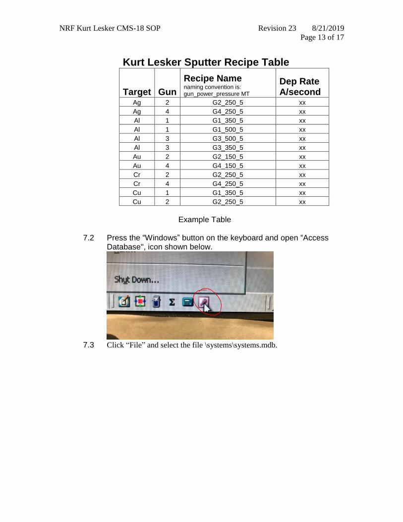
7.2 Press the “Windows” button on the keyboard and open “Access
Database", icon shown below.
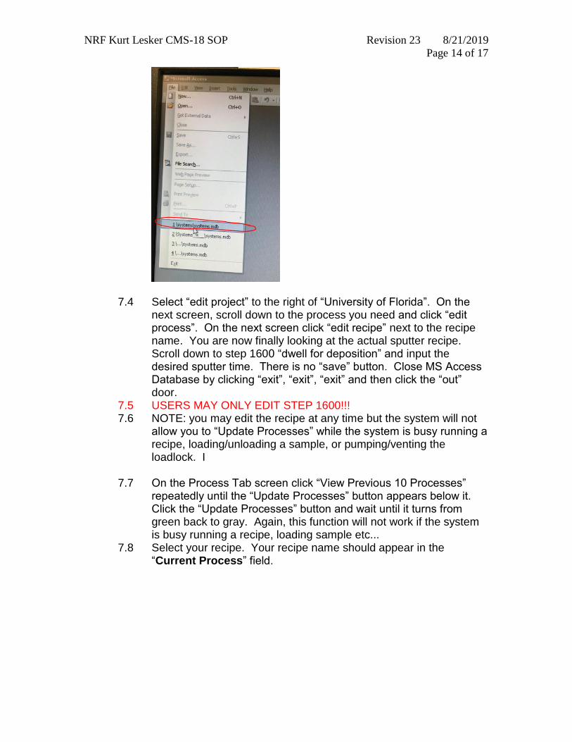
7.3 Click “File” and select the file \systems\systems.mdb.
NRF Kurt Lesker CMS-18 SOP Revision 23 8/21/2019
Page 14 of 17
7.4 Select “edit project” to the right of “University of Florida”. On the next screen, scroll down to the process you need and click “edit process”. On the next screen click “edit recipe” next to the recipe name. You are now finally looking at the actual sputter recipe. Scroll down to step 1600 “dwell for deposition” and input the desired sputter time. There is no “save” button. Close MS Access Database by clicking “exit”, “exit”, “exit” and then click the “out” door.
7.5 USERS MAY ONLY EDIT STEP 1600!!! 7.6 NOTE: you may edit the recipe at any time but the system will not
allow you to “Update Processes” while the system is busy running a recipe, loading/unloading a sample, or pumping/venting the loadlock. I
7.7 On the Process Tab screen click “View Previous 10 Processes” repeatedly until the “Update Processes” button appears below it. Click the “Update Processes” button and wait until it turns from green back to gray. Again, this function will not work if the system is busy running a recipe, loading sample etc...
7.8 Select your recipe. Your recipe name should appear in the “Current Process” field.
NRF Kurt Lesker CMS-18 SOP Revision 23 8/21/2019
Page 15 of 17
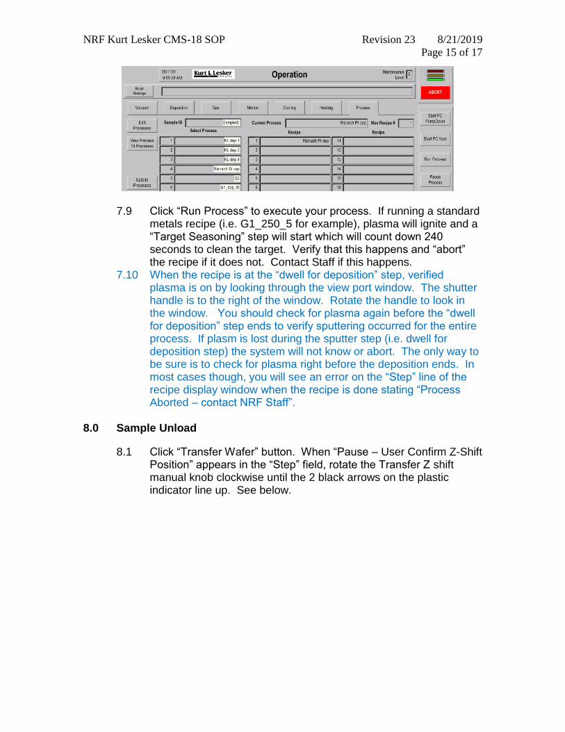
7.9 Click “Run Process” to execute your process. If running a standard metals recipe (i.e. G1_250_5 for example), plasma will ignite and a “Target Seasoning” step will start which will count down 240 seconds to clean the target. Verify that this happens and “abort” the recipe if it does not. Contact Staff if this happens.
7.10 When the recipe is at the “dwell for deposition” step, verified plasma is on by looking through the view port window. The shutter handle is to the right of the window. Rotate the handle to look in the window. You should check for plasma again before the “dwell for deposition” step ends to verify sputtering occurred for the entire process. If plasm is lost during the sputter step (i.e. dwell for deposition step) the system will not know or abort. The only way to be sure is to check for plasma right before the deposition ends. In most cases though, you will see an error on the “Step” line of the recipe display window when the recipe is done stating “Process Aborted – contact NRF Staff”.
8.0 Sample Unload
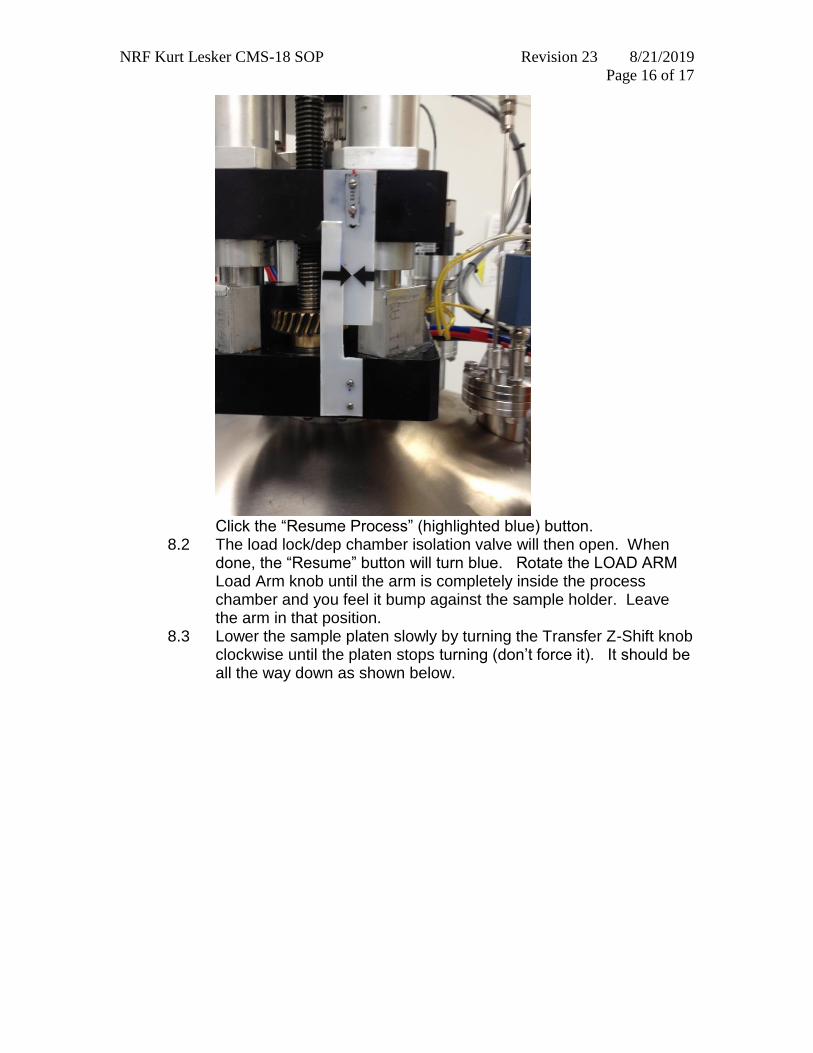
8.1 Click “Transfer Wafer” button. When “Pause – User Confirm Z-Shift Position” appears in the “Step” field, rotate the Transfer Z shift manual knob clockwise until the 2 black arrows on the plastic indicator line up. See below.
NRF Kurt Lesker CMS-18 SOP Revision 23 8/21/2019
Page 16 of 17
Click the “Resume Process” (highlighted blue) button.
8.2 The load lock/dep chamber isolation valve will then open. When done, the “Resume” button will turn blue. Rotate the LOAD ARM Load Arm knob until the arm is completely inside the process chamber and you feel it bump against the sample holder. Leave the arm in that position.
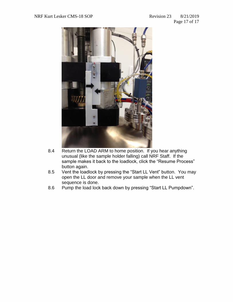
8.3 Lower the sample platen slowly by turning the Transfer Z-Shift knob clockwise until the platen stops turning (don’t force it). It should be all the way down as shown below.
NRF Kurt Lesker CMS-18 SOP Revision 23 8/21/2019
Page 17 of 17
8.4 Return the LOAD ARM to home position. If you hear anything
unusual (like the sample holder falling) call NRF Staff. If the sample makes it back to the loadlock, click the “Resume Process” button again.
8.5 Vent the loadlock by pressing the “Start LL Vent” button. You may open the LL door and remove your sample when the LL vent sequence is done.
8.6 Pump the load lock back down by pressing “Start LL Pumpdown”.