
KUKA.LoadDataDetermination 6 -...
43
KUKA System Technology KUKA.LoadDataDetermination 6.2 For KUKA System Software 8.1, 8.2 and 8.3 KUKA Roboter GmbH Issued: 19.06.2013 Version: KST LoadDataDetermination 6.2 V2 en (PDF)
-
Upload
nguyenmien -
Category
Documents
-
view
279 -
download
3
Transcript of KUKA.LoadDataDetermination 6 -...

KUKA System Technology
KUKA.LoadDataDetermination 6.2
For KUKA System Software 8.1, 8.2 and 8.3
KUKA Roboter GmbH
Issued: 19.06.2013
Version: KST LoadDataDetermination 6.2 V2 en (PDF)

KUKA.LoadDataDetermination 6.2
2 / 43 Issued: 19.06.2013 Version: KST LoadDataDetermination 6.2 V2 en (PDF)
© Copyright 2013
KUKA Roboter GmbH
Zugspitzstraße 140
D-86165 Augsburg
Germany
This documentation or excerpts therefrom may not be reproduced or disclosed to third parties without the express permission of KUKA Roboter GmbH.
Other functions not described in this documentation may be operable in the controller. The user has no claims to these functions, however, in the case of a replacement or service work.
We have checked the content of this documentation for conformity with the hardware and software described. Nevertheless, discrepancies cannot be precluded, for which reason we are not able to guarantee total conformity. The information in this documentation is checked on a regular basis, how-ever, and necessary corrections will be incorporated in the subsequent edition.
Subject to technical alterations without an effect on the function.
Translation of the original documentation
KIM-PS5-DOC
Publication: Pub KST LoadDataDetermination 6.2 en
Book structure: KST LoadDataDetermination 6.2 V1.1
Version: KST LoadDataDetermination 6.2 V2 en (PDF)
Contents
Contents
1 Introduction .................................................................................................. 5
1.1 Target group .............................................................................................................. 5
1.2 Industrial robot documentation ................................................................................... 5
1.3 Representation of warnings and notes ...................................................................... 5
1.4 Trademarks ................................................................................................................ 6
1.5 Terms used ................................................................................................................ 6
2 Product description ..................................................................................... 7
2.1 KUKA.LoadDataDetermination overview ................................................................... 7
2.2 Robot model and physical situation ........................................................................... 7
2.3 Load data ................................................................................................................... 8
2.3.1 Loads on the robot ................................................................................................ 8
2.3.2 Static overloading of the robot .............................................................................. 9
2.3.3 Dynamic overloading of the robot ......................................................................... 9
2.4 Limits to this method of load data determination ....................................................... 10
2.5 Intended use .............................................................................................................. 10
3 Safety ............................................................................................................ 13
4 Installation ................................................................................................... 15
4.1 System requirements ................................................................................................. 15
4.2 Installing or updating KUKA.LoadDataDetermination ................................................ 15
4.3 Uninstalling KUKA.LoadDataDetermination ............................................................... 15
5 Graphical user interface ............................................................................. 17
5.1 Menus ........................................................................................................................ 17
5.2 Overview of buttons ................................................................................................... 17
5.3 Overview of the graphical user interface .................................................................... 17
5.3.1 “Settings” tab ........................................................................................................ 17
5.3.2 “Axis ranges” tab ................................................................................................... 19
5.3.3 “Supplementary load A3” tab ................................................................................ 21
5.3.4 “Info” tab ............................................................................................................... 22
5.3.5 “Load data” tab ..................................................................................................... 24
6 Operation ...................................................................................................... 27
6.1 Overview of load data determination ......................................................................... 27
6.2 Assigning payload data manually .............................................................................. 27
6.3 External energy supply system .................................................................................. 28
6.4 Carrying out load data determination ......................................................................... 28
6.5 Carrying out a test run ............................................................................................... 29
6.6 Carrying out the measurement run ............................................................................ 29
6.7 Assigning the load data .............................................................................................. 31
6.8 Saving the load data .................................................................................................. 31
7 KUKA Service .............................................................................................. 33
7.1 Requesting support .................................................................................................... 33
7.2 KUKA Customer Support ........................................................................................... 33
Index ............................................................................................................. 41
3 / 43Issued: 19.06.2013 Version: KST LoadDataDetermination 6.2 V2 en (PDF)

4 / 43
KUKA.LoadDataDetermination 6.2
Issued: 19.06.2013 Version: KST LoadDataDetermination 6.2 V2 en (PDF)

1 Introduction
1 Introduction
1.1 Target group
This documentation is aimed at users with the following knowledge and skills:
Knowledge of robotics
Advanced knowledge of the robot controller system
Advanced knowledge of dynamic and static loading on the robot
1.2 Industrial robot documentation
The industrial robot documentation consists of the following parts:
Documentation for the manipulator
Documentation for the robot controller
Operating and programming instructions for the KUKA System Software
Documentation relating to options and accessories
Parts catalog on storage medium
Each of these sets of instructions is a separate document.
1.3 Representation of warnings and notes
Safety These warnings are relevant to safety and must be observed.
This warning draws attention to procedures which serve to prevent or remedy emergencies or malfunctions:
Notes These hints serve to make your work easier or contain references to further information.
For optimal use of our products, we recommend that our customers take part in a course of training at KUKA College. Information about the training program can be found at www.kuka.com or can be ob-
tained directly from our subsidiaries.
These warnings mean that it is certain or highly probable that death or severe injuries will occur, if no precautions
are taken.
These warnings mean that death or severe injuries may occur, if no precautions are taken.
These warnings mean that minor injuries may occur, if no precautions are taken.
These warnings mean that damage to property may oc-cur, if no precautions are taken.
These warnings contain references to safety-relevant information or general safety measures. These warnings do not refer to individual hazards or individual pre-
cautionary measures.
Procedures marked with this warning must be followed exactly.
5 / 43Issued: 19.06.2013 Version: KST LoadDataDetermination 6.2 V2 en (PDF)

6 / 43
KUKA.LoadDataDetermination 6.2
1.4 Trademarks
Windows is a trademark of Microsoft Corporation.
1.5 Terms used
Tip to make your work easier or reference to further information.
Term Description
Axis range Range, in degrees or millimeters, within which an axis may move. The axis range is defined by a lower and an upper axis limit.
Measurement trajectory Measurement path
Trajectory Path
KCP The KCP (KUKA Control Panel) teach pendant has all the operator control and display functions required for operating and program-ming the industrial robot.
The KCP variant for the KR C4 is called KUKA smartPAD. The gen-eral term “KCP”, however, is gener-ally used in this documentation.
Issued: 19.06.2013 Version: KST LoadDataDetermination 6.2 V2 en (PDF)
2 Product description
2 Product description
2.1 KUKA.LoadDataDetermination overview
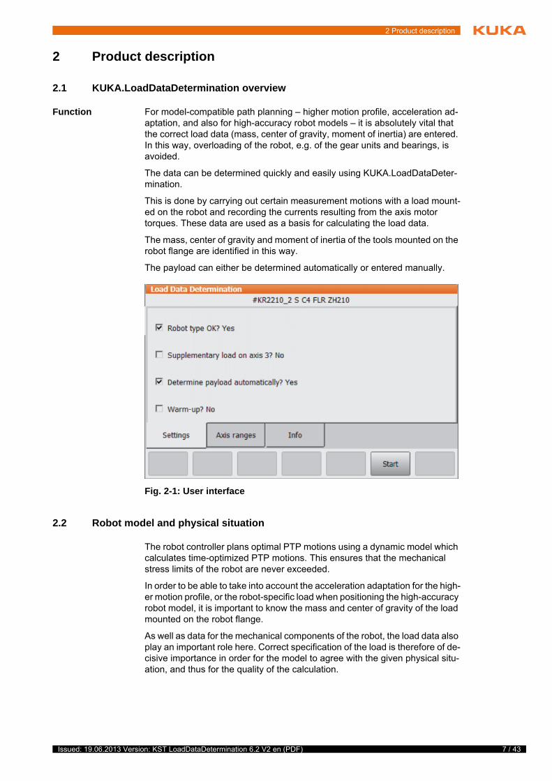
Function For model-compatible path planning – higher motion profile, acceleration ad-aptation, and also for high-accuracy robot models – it is absolutely vital that the correct load data (mass, center of gravity, moment of inertia) are entered. In this way, overloading of the robot, e.g. of the gear units and bearings, is avoided.
The data can be determined quickly and easily using KUKA.LoadDataDeter-mination.
This is done by carrying out certain measurement motions with a load mount-ed on the robot and recording the currents resulting from the axis motor torques. These data are used as a basis for calculating the load data.
The mass, center of gravity and moment of inertia of the tools mounted on the robot flange are identified in this way.
The payload can either be determined automatically or entered manually.
2.2 Robot model and physical situation
The robot controller plans optimal PTP motions using a dynamic model which calculates time-optimized PTP motions. This ensures that the mechanical stress limits of the robot are never exceeded.
In order to be able to take into account the acceleration adaptation for the high-er motion profile, or the robot-specific load when positioning the high-accuracy robot model, it is important to know the mass and center of gravity of the load mounted on the robot flange.
As well as data for the mechanical components of the robot, the load data also play an important role here. Correct specification of the load is therefore of de-cisive importance in order for the model to agree with the given physical situ-ation, and thus for the quality of the calculation.
Fig. 2-1: User interface
7 / 43Issued: 19.06.2013 Version: KST LoadDataDetermination 6.2 V2 en (PDF)
8 / 43
KUKA.LoadDataDetermination 6.2
2.3 Load data
The load data are factored into the calculation of the paths and accelerations and help to optimize the cycle times. The load data must be entered in the ro-bot controller.
2.3.1 Loads on the robot
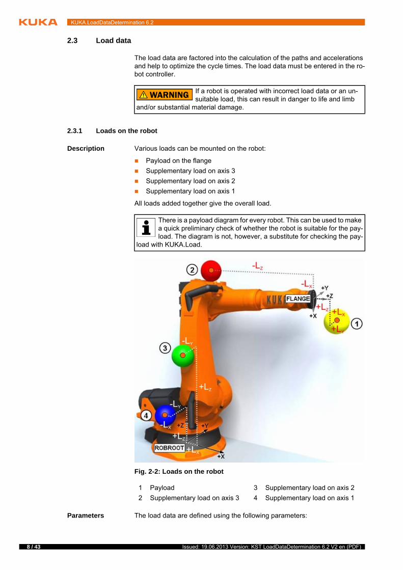
Description Various loads can be mounted on the robot:
Payload on the flange
Supplementary load on axis 3
Supplementary load on axis 2
Supplementary load on axis 1
All loads added together give the overall load.
Parameters The load data are defined using the following parameters:
If a robot is operated with incorrect load data or an un-suitable load, this can result in danger to life and limb
and/or substantial material damage.
There is a payload diagram for every robot. This can be used to make a quick preliminary check of whether the robot is suitable for the pay-load. The diagram is not, however, a substitute for checking the pay-
load with KUKA.Load.
Fig. 2-2: Loads on the robot
1 Payload 3 Supplementary load on axis 2
2 Supplementary load on axis 3 4 Supplementary load on axis 1
Issued: 19.06.2013 Version: KST LoadDataDetermination 6.2 V2 en (PDF)
2 Product description
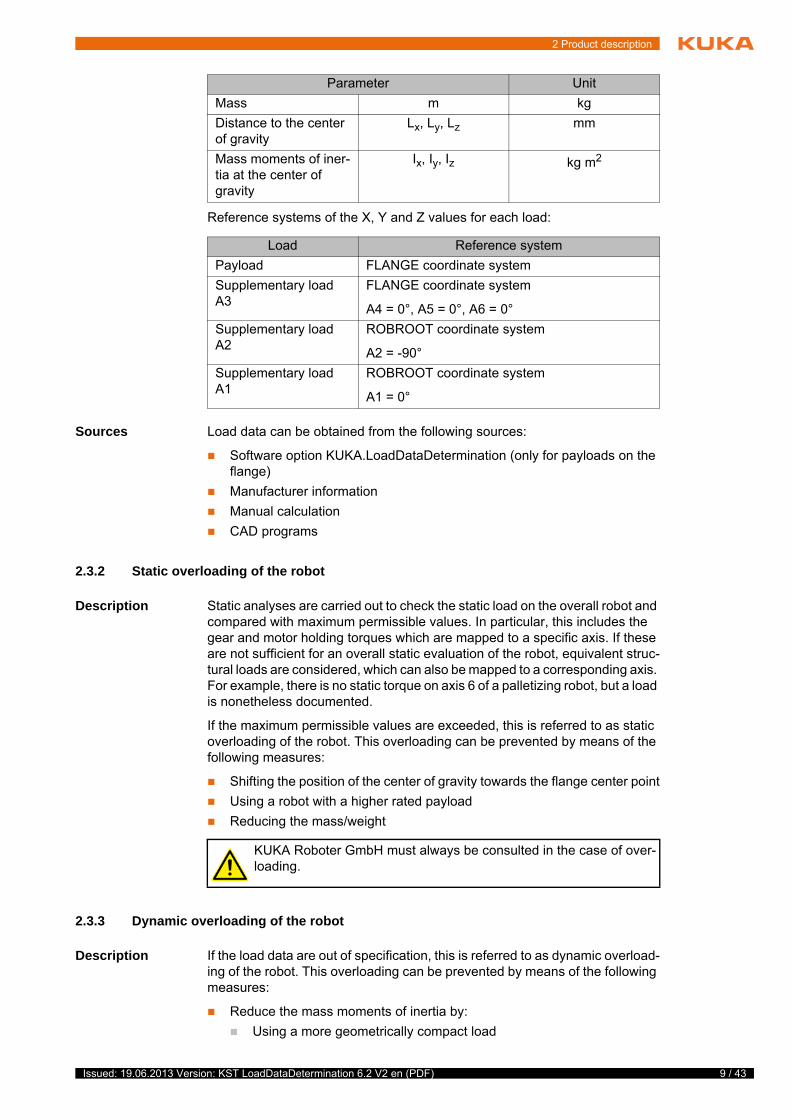
Reference systems of the X, Y and Z values for each load:
Sources Load data can be obtained from the following sources:
Software option KUKA.LoadDataDetermination (only for payloads on the flange)
Manufacturer information
Manual calculation
CAD programs
2.3.2 Static overloading of the robot
Description Static analyses are carried out to check the static load on the overall robot and compared with maximum permissible values. In particular, this includes the gear and motor holding torques which are mapped to a specific axis. If these are not sufficient for an overall static evaluation of the robot, equivalent struc-tural loads are considered, which can also be mapped to a corresponding axis. For example, there is no static torque on axis 6 of a palletizing robot, but a load is nonetheless documented.
If the maximum permissible values are exceeded, this is referred to as static overloading of the robot. This overloading can be prevented by means of the following measures:
Shifting the position of the center of gravity towards the flange center point
Using a robot with a higher rated payload
Reducing the mass/weight
2.3.3 Dynamic overloading of the robot
Description If the load data are out of specification, this is referred to as dynamic overload-ing of the robot. This overloading can be prevented by means of the following measures:
Reduce the mass moments of inertia by:
Using a more geometrically compact load
Parameter Unit
Mass m kg
Distance to the center of gravity
Lx, Ly, Lz mm
Mass moments of iner-tia at the center of gravity
Ix, Iy, Iz kg m2
Load Reference system
Payload FLANGE coordinate system
Supplementary load A3
FLANGE coordinate system
A4 = 0°, A5 = 0°, A6 = 0°
Supplementary load A2
ROBROOT coordinate system
A2 = -90°
Supplementary load A1
ROBROOT coordinate system
A1 = 0°
KUKA Roboter GmbH must always be consulted in the case of over-loading.
9 / 43Issued: 19.06.2013 Version: KST LoadDataDetermination 6.2 V2 en (PDF)

10 / 43
KUKA.LoadDataDetermination 6.2
Reducing the mass
Using a robot with a higher rated payload
2.4 Limits to this method of load data determination
The results of the load data determination may be influenced by the following constraints:
Operating state of the machine
The robot must be at operating temperature. The warm-up function can be selected for this.
Mass of the mounted tool
The lower the mass of the tool mounted on the robot flange, the greater the measurement tolerance. The value for the load should therefore not be less than 20% of the rated payload of the robot.
Robot path
The angular ranges covered are permanently defined. Only the start posi-tion of the robot can be modified within the defined range.
Axis 3 swings ± 2 degrees about the start position.
Axis 5 swings ± 40 degrees about the start position.
Axis 6 swings ± 60 degrees about the start position.
Axis 4 does not move (exception: Transpressors)
The start positions must be as close as possible to the default values (>>> 5.3.2 "“Axis ranges” tab" Page 19). The greater the deviation, the poorer the quality of the identified load data.
KUKA.LoadDataDetermination determines the current loads with the accuracy required to ensure the best possible path planning and optimal rating of the ro-bot. The following accuracy can typically be achieved:
Low payload category
20% of rated payload of robot
Medium payload category
10% of rated payload of robot
High payload category
10% of rated payload of robot
Heavy-duty category
5% of rated payload of robot
2.5 Intended use
KUKA.LoadDataDetermination may only be used on a KR C4 robot controller with the following software:
KUKA System Software 8.1, 8.2 or 8.3
Using it for any other or additional purpose is considered impermissible mis-use. The manufacturer cannot be held liable for any damage resulting from such use. The risk lies entirely with the user.
Operation in accordance with the intended use also involves compliance with the installation and operating instructions in this documentation.
KUKA Roboter GmbH must always be consulted in the case of over-loading.
Issued: 19.06.2013 Version: KST LoadDataDetermination 6.2 V2 en (PDF)

2 Product description
Misuse Any use or application deviating from the intended use is deemed to be imper-missible misuse; examples of such misuse include:
Incorrect configuration (not in compliance with this documentation). This can result in it not being possible to determine the load data as described or with the described accuracy.
11 / 43Issued: 19.06.2013 Version: KST LoadDataDetermination 6.2 V2 en (PDF)

12 / 43
KUKA.LoadDataDetermination 6.2
Issued: 19.06.2013 Version: KST LoadDataDetermination 6.2 V2 en (PDF)

3 Safety
3 Safety
This documentation contains safety instructions which refer specifically to the software described here.
The fundamental safety information for the industrial robot can be found in the “Safety” chapter of the Operating and Programming Instructions for System In-tegrators or the Operating and Programming Instructions for End Users.
The “Safety” chapter in the operating and programming instructions must be observed. Death to persons, severe injuries or considerable damage to property may otherwise result.
13 / 43Issued: 19.06.2013 Version: KST LoadDataDetermination 6.2 V2 en (PDF)

14 / 43
KUKA.LoadDataDetermination 6.2
Issued: 19.06.2013 Version: KST LoadDataDetermination 6.2 V2 en (PDF)

4 Installation
4 Installation
4.1 System requirements
Hardware KR C4 robot controller
Software KUKA System Software 8.1 or 8.2 with Windows XP Embedded
KUKA System Software 8.3 with Windows Embedded Standard 7 V4.x
4.2 Installing or updating KUKA.LoadDataDetermination
Precondition Software on KUKA.USBData stick
No program is selected.
T1 or T2 operating mode
“Expert” user group
Procedure 1. Plug in USB stick.
2. Select Start-up > Install additional software in the main menu.
3. Press New software. If a software package that is on the USB stick is not displayed, press Refresh.
4. Select the entry LoadDataDetermination and press Install. Reply to the request for confirmation with Yes. The files are copied onto the hard drive.
5. Repeat step 4 if another software package is to be installed from this stick.
6. Remove USB stick.
7. It may be necessary to reboot the controller, depending on the additional software. In this case, a corresponding prompt is displayed. Confirm with OK and reboot the robot controller. Installation is resumed and completed.
LOG file A LOG file is created under C:\KRC\ROBOTER\LOG.
4.3 Uninstalling KUKA.LoadDataDetermination
Precondition Expert user group
Procedure 1. Select Start-up > Install additional software in the main menu. All addi-tional programs installed are displayed.
2. Select the entry LoadDataDetermination and press Uninstall. Reply to the request for confirmation with Yes. Uninstallation is prepared.
3. Reboot the robot controller. Uninstallation is resumed and completed.
LOG file A LOG file is created under C:\KRC\ROBOTER\LOG.
It is advisable to archive all relevant data before updating a software package.
Only the KUKA.USB data stick may be used. Data may be lost or modified if any other USB stick is used.
It is advisable to archive all relevant data before uninstalling a soft-ware package.
15 / 43Issued: 19.06.2013 Version: KST LoadDataDetermination 6.2 V2 en (PDF)

16 / 43
KUKA.LoadDataDetermination 6.2
Issued: 19.06.2013 Version: KST LoadDataDetermination 6.2 V2 en (PDF)

5 Graphical user interface
5 Graphical user interface
5.1 Menus
The following menu is specific to this technology package:
Start-up
Service
Load Data Determination
5.2 Overview of buttons
The following buttons are available:
5.3 Overview of the graphical user interface
5.3.1 “Settings” tab
Description The “Settings” tab has the following functions:
Robot type OK?
The robot types are optimized for load data determination with the stan-dard set of motors. It is therefore necessary to specify the correct robot type. On starting the load data determination, the motor set is checked to-gether with the robot name. If the robot is available in the current load data version, “Robot type OK?” is automatically set to Yes.
If the robot with its motor set is not recognized (e.g. due to a change in the robot’s motor set for technical reasons, which has not yet been updated in the LDD database), the message “Robot with this set of motors not adjust-ed for LDD” is displayed in the message window.
This menu is only available if no program has been selected.
Button Description
Start Starts the KRL pendulum program.
Load ldf Opens the axis angle ranges from the directories C:\KRC\ROBOTER\IR_SPEC\IDF and E:\.
Save ldf Saves the axis angle ranges.
Read axes Calculates the axis angle ranges on the basis of the current robot position.
Save Confirms an action, such as Save Idf, or entries in the Supplementary load A3 tab.
Default Resets entered values to the original values.
Assign tool Assigns the displayed load data automatically in $CONFIG.DAT to the tool selected in the selec-tion box.
New meas Rejects the calculated load data and switches to the Settings tab.
USB Saves the load data determination onto the KUKA.USB data stick.
Backup Creates a backup of the data under D:\Load-DataDetermination....
Logging Opens log entries on the Info tab.
17 / 43Issued: 19.06.2013 Version: KST LoadDataDetermination 6.2 V2 en (PDF)

18 / 43
KUKA.LoadDataDetermination 6.2
Using the checkbox “Robot type OK? Yes”, it is possible to select manually from a selection box a different robot from the one shown above, but which has the same motor set.
Supplementary load on axis 3?
If “Supplementary load on axis 3?” is activated, the “Supplementary load A3” tab is opened. Supplementary load data can be entered here.
Determine payload automatically?
If the payload should be determined automatically, this box must be acti-vated.
If the payload should not be determined automatically, this box must be deactivated. The payload can then be entered manually.
Warm-up?
If the robot is not at operating temperature, a warm-up can be set.
Always consult KUKA Roboter GmbH if the message “Robot with this set of motors not adjusted for LDD” is
generated. Damage to property may otherwise result.
Fig. 5-1: Selection box
To avoid damage to the robot, it must be ensured that the correct robot type has been selected.
The number of robot types supported by load data determination is constantly being expanded. Information on which robot types are cur-rently supported can be obtained from KUKA Roboter GmbH.
The robot must be at operating temperature so that the data determined correspond to the actual parameters. If
the robot is not at operating temperature, a warm-up must be carried out. Damage to the robot may otherwise result.
Issued: 19.06.2013 Version: KST LoadDataDetermination 6.2 V2 en (PDF)

5 Graphical user interface
5.3.2 “Axis ranges” tab
Description In practice, there are often work envelope constraints such that the robot is only able to execute motions within certain angular ranges in order to avoid the risk of colliding with obstacles in the work envelope. Despite such predefined angular ranges, it is nonetheless possible to influence the work envelope re-quired for the load data determination:
Axis A3 must be positioned more-or-less horizontal in relation to the floor. This means that the sum of A2 and A3 must be practically zero.
The start position of axis A5 can be shifted by ± 40 degrees about the zero position. The following conditions relating to the start position must be met:
Maximum
intervals
- 2 degrees < A2 + A3 < 2 degrees (e.g. also A2 = -80 degrees and A3 = 80 degrees)
- 40 degrees < A5 < 40 degrees
A6 at any position up to the software limit switches
Optimal start position:
A2 = -90 degrees
A3 = 90 degrees
A4 = 0 degrees
A5 = 0 degrees
A6 = 0 degrees
If the work envelope permits this, the cannon position should be selected for the identification process.
For the pendulum motions, axis A4 is always moved to 0 (zero) degrees by the program. The user should therefore check beforehand that this position is compatible with the work envelope.
Fig. 5-2: “Settings” tab
Different intervals apply to the Transpressors.
If axis A4 is not at 0 (zero) degrees, the message “Caution: The an-gles for axis 4 were set to zero degrees!” is displayed.
19 / 43Issued: 19.06.2013 Version: KST LoadDataDetermination 6.2 V2 en (PDF)

20 / 43
KUKA.LoadDataDetermination 6.2
The start position of axis A5 should be as close as possible to 0 (zero) de-grees. The greater the deviation from 0 (zero) degrees, the poorer the quality of the identified load data.
Since the current robot position is used to calculate the intervals, it is possible that a software limit switch may be violated. This is checked by the program and the start position must be modified as required. Violation of the software limit switches is indicated by a status message.
The midpoint of the axis range for axis A6 is automatically set to the multiple of 90 degrees nearest to the current axis position (e.g. from 87 degrees to 90 degrees, or from 145 degrees to 180 degrees). For the second motion, the midpoint of the axis range is offset +90 degrees from the first motion.
Axis angle ranges On the “Axis ranges” tab, the axis positions of axes A1 and A2 and the motion ranges of axes A3 to A6 are displayed. Using the buttons Read axes, Save Idf and Load ldf, the current axis angles can be read in and the settings can be saved or loaded, respectively.
The entries in the boxes for axes A1 and A2 correspond to the current robot position.
Axis A4 is not moved and is thus always set to 0 degrees during the identifi-cation process, irrespective of its current position.
For axes A3, A5 and A6, the interval is calculated from the current robot posi-tion and a predefined angular range. The following applies here:
Axis A3 ± 2 degrees, i.e. [curr.pos. -- 2 degrees, curr.pos. + 2 degrees]
Axis A5 ± 40 degrees, i.e. [curr.pos. -- 40 degrees, curr.pos. + 40 degrees]
Axis A6 ± 60 degrees, i.e. [curr.pos. -- 60 degrees, curr.pos. + 60 degrees]
The identification process consists of three separate measurements.
In the first measurement, only axes A3 and A5 are moved.
In the second measurement, axis A6 is rotated through 90 degrees and only axis A5 is moved.
In the third measurement, an individual motion of axis A6 about the start-ing position of the robot is carried out.
Path planning
(Transpressors)
For Transpressors, the following axes are moved:
First motion: Axes A3 + A5
Second motion: Axis A4
Third motion: Axis A6 with A4 rotated through 90 degrees.
Overview of
default angular
ranges
The default angular ranges are contained in the following IDF files:
DEFAULT.IDF
Default angular ranges for standard robots
DEFAULT_WIH.IDF
Default angular ranges for Transpressors
*.idf DEFAULT.IDF DEFAULT_WIH.IDF
Axis Minimum Maximum Minimum Maximum
A1 0 degrees 0 degrees 0 degrees 0 degrees
A2 -90 degrees -90 degrees -90 degrees -90 degrees
A3 88 degrees 92 degrees 90 degrees 94 degrees
A4 0 degrees 0 degrees -40 degrees 40 degrees
A5 -40 degrees 40 degrees 30 degrees 110 degrees
A6 -60 degrees 60 degrees -40 degrees 40 degrees
Issued: 19.06.2013 Version: KST LoadDataDetermination 6.2 V2 en (PDF)

5 Graphical user interface
5.3.3 “Supplementary load A3” tab
Description The following values can be entered on the “Supplementary load A3” tab:
Mass in kg
Center of gravity in mm for Lx, Ly, Lz
Inertia in kg m2 for lx, ly, lz
The input boxes for the mass, inertia and center of gravity already contain the preset values from the file $CONFIG.DAT.
If the values entered in the file $CONFIG.DAT are the default values (mass = -1), the values from the file $ROBCOR.DAT are used.
Fig. 5-3: “Axis ranges” tab
These values are not saved in the file $CONFIG.DAT. In-correct supplementary load data will lead to inaccuracy
and deviation when determining the load data.
21 / 43Issued: 19.06.2013 Version: KST LoadDataDetermination 6.2 V2 en (PDF)

22 / 43
KUKA.LoadDataDetermination 6.2
5.3.4 “Info” tab
Description The “Info” tab displays the following version information and log entries:
Version information:
Load data determination
Path planning
Robot types
Log entries:
Log date
Log entry
To show the log entries, it is necessary to switch to the user group “Adminis-trator”.
Procedure 1. Select Configuration > User group in the main menu.
2. Press Log On and select the user group “Administrator”.
3. Enter password and confirm with Log On.
The Logging button then appears. If this is pressed, a selection box opens, in which the log date can be selected.
Fig. 5-4: “Supplementary load A3” tab
Issued: 19.06.2013 Version: KST LoadDataDetermination 6.2 V2 en (PDF)

5 Graphical user interface
Fig. 5-5: “Info” tab
Fig. 5-6: Log entries
23 / 43Issued: 19.06.2013 Version: KST LoadDataDetermination 6.2 V2 en (PDF)

24 / 43
KUKA.LoadDataDetermination 6.2
5.3.5 “Load data” tab
Description Once the load data determination is completed, this tab is generated and add-ed. Here the calculated load data are shown.
The following settings can be made here:
Discard the calculated load data
Pressing the New meas button discards the calculated load data. The pro-gram switches to the Settings tab.
Assign the load data to a tool
Pressing the Assign tool button assigns the displayed load data automat-ically in $CONFIG.DAT to the tool number selected in the selection box.
Save load data to disk
Pressing the USB button saves the load data in the file load.txt to the USB stick.
Create a backup of the load data determination
Pressing the Backup button saves a backup of the load data determina-tion process on D:\LoadDataDetermination.
To show more than just the tool number here, a tool name can be as-signed to the tool number.In the main menu, select Start-up > Measure > Tool > Change
name. Mark the tool number and press Name. Enter a tool name and confirm with Save. The tool name is saved.
Only the KUKA.USB data stick may be used. Data may be lost or modified if any other USB stick is used.
When a backup is created, the load data determined and other project information (as in KUKA.Load) are saved in the project file KukaLo-adProject.*serialnumber*.XML. This XML file is saved in the directory
C:\KRC\Roboter\IR_SPEC\L_IDENT.
Issued: 19.06.2013 Version: KST LoadDataDetermination 6.2 V2 en (PDF)

5 Graphical user interface
Fig. 5-7: “Load data” tab
25 / 43Issued: 19.06.2013 Version: KST LoadDataDetermination 6.2 V2 en (PDF)

26 / 43
KUKA.LoadDataDetermination 6.2
Issued: 19.06.2013 Version: KST LoadDataDetermination 6.2 V2 en (PDF)
6 Operation
6 Operation
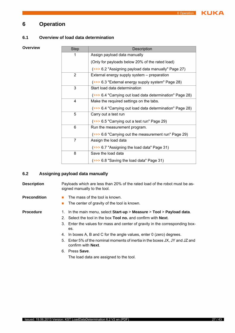
6.1 Overview of load data determination
Overview
6.2 Assigning payload data manually
Description Payloads which are less than 20% of the rated load of the robot must be as-signed manually to the tool.
Precondition The mass of the tool is known.
The center of gravity of the tool is known.
Procedure 1. In the main menu, select Start-up > Measure > Tool > Payload data.
2. Select the tool in the box Tool no. and confirm with Next.
3. Enter the values for mass and center of gravity in the corresponding box-es.
4. In boxes A, B and C for the angle values, enter 0 (zero) degrees.
5. Enter 5% of the nominal moments of inertia in the boxes JX, JY and JZ and confirm with Next.
6. Press Save.
The load data are assigned to the tool.
Step Description
1 Assign payload data manually
(Only for payloads below 20% of the rated load)
(>>> 6.2 "Assigning payload data manually" Page 27)
2 External energy supply system – preparation
(>>> 6.3 "External energy supply system" Page 28)
3 Start load data determination
(>>> 6.4 "Carrying out load data determination" Page 28)
4 Make the required settings on the tabs.
(>>> 6.4 "Carrying out load data determination" Page 28)
5 Carry out a test run
(>>> 6.5 "Carrying out a test run" Page 29)
6 Run the measurement program.
(>>> 6.6 "Carrying out the measurement run" Page 29)
7 Assign the load data
(>>> 6.7 "Assigning the load data" Page 31)
8 Save the load data
(>>> 6.8 "Saving the load data" Page 31)
27 / 43Issued: 19.06.2013 Version: KST LoadDataDetermination 6.2 V2 en (PDF)

28 / 43
KUKA.LoadDataDetermination 6.2
6.3 External energy supply system
If a weld gun is mounted, the weld gun electrodes and any other parts mount-ed on the tool must be immobilized, e.g. by means of fasteners.
Riveting guns with pneumatic compensation must be pressurized with com-pressed air during the pendulum motions.
6.4 Carrying out load data determination
Precondition KUKA.LoadDataDetermination is correctly installed.
No program is selected
Procedure 1. In the main menu, select Start-up > Service > Load data determination.
The LdePlugIn is opened.
2. Carry out the desired settings on the “Settings” and “Axis ranges” tabs.
(>>> 5.3.1 "“Settings” tab" Page 17)
(>>> 5.3.2 "“Axis ranges” tab" Page 19)
Fig. 6-1: Entering payload data
It is possible for an external energy supply system mounted on the tool to take part in the pendulum motions. For this, the following steps must be taken:
Slacken the spring of the dress package.
Select the start position of the robot in such a way that the dress package is subjected to minimal stress for the start positions of all 3 measurement motions.
Payloads which are less than 20% of the rated load of the robot must be assigned manually to the tool (>>> 6.2 "Assigning payload data manually" Page 27).
Issued: 19.06.2013 Version: KST LoadDataDetermination 6.2 V2 en (PDF)

6 Operation
3. Press Start.
The system program is opened.
4. Hold down the Start key and one of the enabling switches on the KCP until Programmed path reached (BCO) appears in the message window.
5. Press the Start key and one of the enabling switches on the KCP.
The prompt Test runs before measurement? appears in the message window.
If the prompt is confirmed with Yes, the test run is started. If the prompt is answered with No, the measurement run is started. Pressing the End but-ton terminates the program.
(>>> 6.5 "Carrying out a test run" Page 29)
(>>> 6.6 "Carrying out the measurement run" Page 29)
6.5 Carrying out a test run
Description During the test run, the workspace required for all three measurement motions can be checked for collisions. First, the axes are moved to the maximum an-gular positions of the second and third measurement trajectories at 10% over-ride. This is followed by the complete mixed motion of axes A3 and A5 at 100% override in T1, otherwise at 30% override.
Procedure Confirm the message Test runs before measurement? with Yes.
The test run is performed.
At the end of the test run, confirm the message Start the measurement runs with Yes. (>>> 6.6 "Carrying out the measurement run" Page 29).
6.6 Carrying out the measurement run
Overview Once the program has been started, the normal user interface is displayed on the KCP. A system program is displayed in the program window. The program displayed depends on the language selected in the input mask.
The robot must be at operating temperature so that the data determined correspond to the actual parameters. If
the robot is not at operating temperature, a warm-up must be carried out. Damage to the robot may otherwise result.
If there is no T2/Automatic mode available, switch to T1/Automatic External mode. For this, activate the file LdeExt.REG by double-click-ing on it in the installation directory …\INTERNAT\KRCUPD.
The KRL program must be started in T1 mode. After selection, switch to Au-tomatic External mode.
The safe velocity in T2 (250 mm/s) may only be increased by means of a deliberate operator action. In load data determination, this is as-sured by appropriate user prompting. For easier operator control, it is
advisable to carry out load data determination in the Automatic or Automatic External mode provided the safety facilities allow this.
Always perform a test run before the measurement run. Serious injuries or damage to property may otherwise re-
sult.
Language System program
Deutsch $DE_IDENT.SRC
English $EN_IDENT.SRC
29 / 43Issued: 19.06.2013 Version: KST LoadDataDetermination 6.2 V2 en (PDF)

30 / 43
KUKA.LoadDataDetermination 6.2
Description The measurement program is executed as follows:
Procedure
1. Hold down the Start key and one of the enabling switches until the mes-sage “Programmed path reached (BCO)” appears in the message window.
2. Press the Start key and one of the enabling switches on the KCP.
The following query appears in the message window: “Test runs before measurement?”.
If the query is confirmed with Yes, the test run is started. If the query is an-swered with No, the message “Start the measurement runs” is displayed. Press OK.
Pressing End terminates the program.
Français $FR_IDENT.SRC
Español $ES_IDENT.SRC
Italiano $IT_IDENT.SRC
The system programs “$DE_IDENT.SRC”, “$EN_IDENT.SRC”, “$FR_IDENT.SRC”,
“$ES_IDENT.SRC” and “$IT_IDENT.SRC” must on no account be changed! Failure to observe this may result in death to persons, severe injuries or dam-age to property.
Language System program
Program execution structure
Program item Description
Activation, BCO, test motion Initialization of the program, motion to the start point and possible test motions.
Measurement trajectory, axes A3 and A5
Measurement run of axes A3 and A5.
Calculation, part 1 The first part of the load data is cal-culated.
Activation of the second motion Initialization of the next motion.
Measurement trajectory, axis A5 Motion to start point and measure-ment run for axis A5. Axis A6 is rotated by 90 degrees from its start position.
Calculation, part 2 The second part of the load data is calculated.
Activation of the third motion Initialization of the third motion.
Measurement trajectory, axis A6 Motion to start point and measure-ment run for axis A6.
Calculation, part 3 The third part of the load data is cal-culated.
Motion to start point Motion to the start position of the robot.
The measurement run starts automatically after confirmation of the message “Start the measurement runs” with OK.
Always perform a test run before the measurement run. Serious injuries or damage to property may otherwise re-
sult.
Issued: 19.06.2013 Version: KST LoadDataDetermination 6.2 V2 en (PDF)

6 Operation
3. The message “Start the measurement runs” appears before the first mea-surement motion.
4. Press OK to confirm the message.
The robot now executes the first measurement motion and then calculates part of the load data.
Before each subsequent measurement motion, the following message is displayed: “Move to start point of second (or third) path and start measure-ment”.
5. Press OK to confirm the message.
At the end of the third calculation, the Load data (>>> 5.3.5 "“Load data” tab" Page 24) tab is displayed.
6.7 Assigning the load data
Description If the measurement run is completed without interruption, the actual calcula-tion is carried out and the program is terminated. The load on the robot is then checked (corresponds to the load test in KUKA.Load).
(>>> 2.3.2 "Static overloading of the robot" Page 9)
(>>> 2.3.3 "Dynamic overloading of the robot" Page 9)
If the block pointer is situated in the program line “ENDE”, the measurement results are displayed on the “Load data” tab. The load data can then be as-signed to a tool (>>> 5.3.5 "“Load data” tab" Page 24).
Procedure 1. Select a tool from the tool selection box on the Load data tab.
2. Press Assign tool.
The load data are assigned to the tool.
6.8 Saving the load data
Description The calculated load data can be saved to the USB stick or on the hard drive.
The robot always moves to the start point of the next path. This is done at 30% override. The measurement
motion is then started at once.It is not possible to adjust the override during a measurement run.The robot always stops between the individual motions in order to carry out calculations.Before confirming the message, always make sure that nobody is in the ro-bot’s work envelope.Failure to observe this precaution may result in severe injuries or consider-able damage to property.
After the load data have been determined, the load data determined and other project information (as in KUKA.Load) are automatically saved in the project file KukaLoadProject.*serialnumber*.XML. This
XML file is saved in the directory C:\KRC\Roboter\IR_SPEC\L_IDENT.
Overloading and damage to the robot. If the robot is overloaded, a corresponding message appears. If this load is assigned to a tool, an additional message is generated. KUKA Roboter GmbH must always
be consulted in such cases.
If a robot is operated with incorrect load data or an un-suitable load, this can result in danger to life and limb
and/or substantial material damage.
31 / 43Issued: 19.06.2013 Version: KST LoadDataDetermination 6.2 V2 en (PDF)

32 / 43
KUKA.LoadDataDetermination 6.2
Procedure Saving the calculated data to the USB stick
1. Plug in USB stick.
2. Press USB to save the calculated data to the USB stick.
A file “Load_YYYYMMDD_HHMM.TXT” is created on the USB stick.
Procedure Saving the calculated data to the hard drive
Press Backup to archive the calculated data on the hard drive.
The file is saved as D:\LoadDataDetermination\YYYYMMDD_HHMM. All TXT files from the directory C:\KRC\Roboter\IR_SPEC\L_IDENT are then deleted in order to save disk capacity for a possible archive.
Only the KUKA.USB data stick may be used. Data may be lost or modified if any other USB stick is used.
Issued: 19.06.2013 Version: KST LoadDataDetermination 6.2 V2 en (PDF)

7 KUKA Service
7 KUKA Service
7.1 Requesting support
Introduction The KUKA Roboter GmbH documentation offers information on operation and provides assistance with troubleshooting. For further assistance, please con-tact your local KUKA subsidiary.
Information The following information is required for processing a support request:
Model and serial number of the robot
Model and serial number of the controller
Model and serial number of the linear unit (if applicable)
Model and serial number of the energy supply system (if applicable)
Version of the KUKA System Software
Optional software or modifications
Archive of the software
For KUKA System Software V8: instead of a conventional archive, gener-ate the special data package for fault analysis (via KrcDiag).
Application used
Any external axes used
Description of the problem, duration and frequency of the fault
7.2 KUKA Customer Support
Availability KUKA Customer Support is available in many countries. Please do not hesi-tate to contact us if you have any questions.
Argentina Ruben Costantini S.A. (Agency)
Luis Angel Huergo 13 20
Parque Industrial
2400 San Francisco (CBA)
Argentina
Tel. +54 3564 421033
Fax +54 3564 428877
Australia Headland Machinery Pty. Ltd.
Victoria (Head Office & Showroom)
95 Highbury Road
Burwood
Victoria 31 25
Australia
Tel. +61 3 9244-3500
Fax +61 3 9244-3501
www.headland.com.au
33 / 43Issued: 19.06.2013 Version: KST LoadDataDetermination 6.2 V2 en (PDF)

34 / 43
KUKA.LoadDataDetermination 6.2
Belgium KUKA Automatisering + Robots N.V.
Centrum Zuid 1031
3530 Houthalen
Belgium
Tel. +32 11 516160
Fax +32 11 526794
www.kuka.be
Brazil KUKA Roboter do Brasil Ltda.
Travessa Claudio Armando, nº 171
Bloco 5 - Galpões 51/52
Bairro Assunção
CEP 09861-7630 São Bernardo do Campo - SP
Brazil
Tel. +55 11 4942-8299
Fax +55 11 2201-7883
www.kuka-roboter.com.br
Chile Robotec S.A. (Agency)
Santiago de Chile
Chile
Tel. +56 2 331-5951
Fax +56 2 331-5952
www.robotec.cl
China KUKA Robotics China Co.,Ltd.
Songjiang Industrial Zone
No. 388 Minshen Road
201612 Shanghai
China
Tel. +86 21 6787-1888
Fax +86 21 6787-1803
www.kuka-robotics.cn
Germany KUKA Roboter GmbH
Zugspitzstr. 140
86165 Augsburg
Germany
Tel. +49 821 797-4000
Fax +49 821 797-1616
www.kuka-roboter.de
Issued: 19.06.2013 Version: KST LoadDataDetermination 6.2 V2 en (PDF)

7 KUKA Service
France KUKA Automatisme + Robotique SAS
Techvallée
6, Avenue du Parc
91140 Villebon S/Yvette
France
Tel. +33 1 6931660-0
Fax +33 1 6931660-1
www.kuka.fr
India KUKA Robotics India Pvt. Ltd.
Office Number-7, German Centre,
Level 12, Building No. - 9B
DLF Cyber City Phase III
122 002 Gurgaon
Haryana
India
Tel. +91 124 4635774
Fax +91 124 4635773
www.kuka.in
Italy KUKA Roboter Italia S.p.A.
Via Pavia 9/a - int.6
10098 Rivoli (TO)
Italy
Tel. +39 011 959-5013
Fax +39 011 959-5141
www.kuka.it
Japan KUKA Robotics Japan K.K.
YBP Technical Center
134 Godo-cho, Hodogaya-ku
Yokohama, Kanagawa
240 0005
Japan
Tel. +81 45 744 7691
Fax +81 45 744 7696
Canada KUKA Robotics Canada Ltd.
6710 Maritz Drive - Unit 4
Mississauga
L5W 0A1
Ontario
Canada
Tel. +1 905 670-8600
Fax +1 905 670-8604
www.kuka-robotics.com/canada
35 / 43Issued: 19.06.2013 Version: KST LoadDataDetermination 6.2 V2 en (PDF)

36 / 43
KUKA.LoadDataDetermination 6.2
Korea KUKA Robotics Korea Co. Ltd.
RIT Center 306, Gyeonggi Technopark
1271-11 Sa 3-dong, Sangnok-gu
Ansan City, Gyeonggi Do
426-901
Korea
Tel. +82 31 501-1451
Fax +82 31 501-1461
Malaysia KUKA Robot Automation Sdn Bhd
South East Asia Regional Office
No. 24, Jalan TPP 1/10
Taman Industri Puchong
47100 Puchong
Selangor
Malaysia
Tel. +60 3 8061-0613 or -0614
Fax +60 3 8061-7386
Mexico KUKA de México S. de R.L. de C.V.
Progreso #8
Col. Centro Industrial Puente de Vigas
Tlalnepantla de Baz
54020 Estado de México
Mexico
Tel. +52 55 5203-8407
Fax +52 55 5203-8148
www.kuka-robotics.com/mexico
Norway KUKA Sveiseanlegg + Roboter
Sentrumsvegen 5
2867 Hov
Norway
Tel. +47 61 18 91 30
Fax +47 61 18 62 00
Austria KUKA Roboter Austria GmbH
Vertriebsbüro Österreich
Regensburger Strasse 9/1
4020 Linz
Austria
Tel. +43 732 784752
Fax +43 732 793880
www.kuka-roboter.at
Issued: 19.06.2013 Version: KST LoadDataDetermination 6.2 V2 en (PDF)

7 KUKA Service
Poland KUKA Roboter Austria GmbH
Spółka z ograniczoną odpowiedzialnością
Oddział w Polsce
Ul. Porcelanowa 10
40-246 Katowice
Poland
Tel. +48 327 30 32 13 or -14
Fax +48 327 30 32 26
Portugal KUKA Sistemas de Automatización S.A.
Rua do Alto da Guerra n° 50
Armazém 04
2910 011 Setúbal
Portugal
Tel. +351 265 729780
Fax +351 265 729782
Russia OOO KUKA Robotics Rus
Webnaja ul. 8A
107143 Moskau
Russia
Tel. +7 495 781-31-20
Fax +7 495 781-31-19
kuka-robotics.ru
Sweden KUKA Svetsanläggningar + Robotar AB
A. Odhners gata 15
421 30 Västra Frölunda
Sweden
Tel. +46 31 7266-200
Fax +46 31 7266-201
Switzerland KUKA Roboter Schweiz AG
Industriestr. 9
5432 Neuenhof
Switzerland
Tel. +41 44 74490-90
Fax +41 44 74490-91
www.kuka-roboter.ch
37 / 43Issued: 19.06.2013 Version: KST LoadDataDetermination 6.2 V2 en (PDF)

38 / 43
KUKA.LoadDataDetermination 6.2
Spain KUKA Robots IBÉRICA, S.A.
Pol. Industrial
Torrent de la Pastera
Carrer del Bages s/n
08800 Vilanova i la Geltrú (Barcelona)
Spain
Tel. +34 93 8142-353
Fax +34 93 8142-950
www.kuka-e.com
South Africa Jendamark Automation LTD (Agency)
76a York Road
North End
6000 Port Elizabeth
South Africa
Tel. +27 41 391 4700
Fax +27 41 373 3869
www.jendamark.co.za
Taiwan KUKA Robot Automation Taiwan Co., Ltd.
No. 249 Pujong Road
Jungli City, Taoyuan County 320
Taiwan, R. O. C.
Tel. +886 3 4331988
Fax +886 3 4331948
www.kuka.com.tw
Thailand KUKA Robot Automation (M)SdnBhd
Thailand Office
c/o Maccall System Co. Ltd.
49/9-10 Soi Kingkaew 30 Kingkaew Road
Tt. Rachatheva, A. Bangpli
Samutprakarn
10540 Thailand
Tel. +66 2 7502737
Fax +66 2 6612355
www.kuka-roboter.de
Czech Republic KUKA Roboter Austria GmbH
Organisation Tschechien und Slowakei
Sezemická 2757/2
193 00 Praha
Horní Počernice
Czech Republic
Tel. +420 22 62 12 27 2
Fax +420 22 62 12 27 0
Issued: 19.06.2013 Version: KST LoadDataDetermination 6.2 V2 en (PDF)

7 KUKA Service
Hungary KUKA Robotics Hungaria Kft.
Fö út 140
2335 Taksony
Hungary
Tel. +36 24 501609
Fax +36 24 477031
USA KUKA Robotics Corporation
51870 Shelby Parkway
Shelby Township
48315-1787
Michigan
USA
Tel. +1 866 873-5852
Fax +1 866 329-5852
www.kukarobotics.com
UK KUKA Automation + Robotics
Hereward Rise
Halesowen
B62 8AN
UK
Tel. +44 121 585-0800
Fax +44 121 585-0900
39 / 43Issued: 19.06.2013 Version: KST LoadDataDetermination 6.2 V2 en (PDF)

40 / 43
KUKA.LoadDataDetermination 6.2
Issued: 19.06.2013 Version: KST LoadDataDetermination 6.2 V2 en (PDF)

Index
Index
AAxis range 6
BButtons, overview 17
CCenter of gravity 9
DDocumentation, industrial robot 5Dynamic overloading of the robot 9
EEnergy supply system, external 28Execution of measurement run 29
GGraphical user interface 17
IInstallation 15Installing KUKA.LoadDataDetermination 15Intended use 10Introduction 5
KKCP 6KUKA Customer Support 33KUKA.LoadDataDetermination, uninstalling 15
LLoad data 8Load data determination, executing 28Load data, assignment 31Load data, saving 31Loads on the robot 8
MMass 9Mass moments of inertia 9Measurement run, executing 29Measurement trajectory 6Menus 17
OOperation 27Overall load 8Overview, KUKA.LoadDataDetermination 7Overview, load data determination 27
PPayload data, manual assignment 27Payloads 8Product description 7
SSafety 13
Safety instructions 5Saving the load data 31Service, KUKA Roboter 33Static overloading of the robot 9Support request 33System requirements 15
TTab, Axis ranges 19Tab, Info 22Tab, Load data 24Tab, Settings 17Tab, Supplementary load A3 21Target group 5Terms used 6Test run, executing 29Trademarks 6Training 5Trajectory 6
UUninstallation, KUKA.LoadDataDetermination 15Updating KUKA.LoadDataDetermination 15
WWarnings 5
41 / 43Issued: 19.06.2013 Version: KST LoadDataDetermination 6.2 V2 en (PDF)

42 / 43
KUKA.LoadDataDetermination 6.2
Issued: 19.06.2013 Version: KST LoadDataDetermination 6.2 V2 en (PDF)

43 / 43Issued: 19.06.2013 Version: KST LoadDataDetermination 6.2 V2 en (PDF)
KUKA.LoadDataDetermination 6.2


