
Kubler Sendix 5000/5020 Standard Optical Incremental Encoders · Incremental encoders . Incremental...
14
IP -40° ... +85°C 2/22 RoHS Incremental encoders Incremental encoders Push-Pull / RS422 / Open collector Standard optical Sendix 5000 / 5020 (shaft / hollow shaft) Surface protection salt spray-tested optional Optical sensor Due to their sturdy bearing construction in Safety-Lock™ Design, the Sendix 5000 and 5020 offer high resistance against vibration and installation errors. The rugged housing, high protection level of up to IP67, as well as the wide temperature range of -40°C up to +85°C, make this product range the perfect encoder for all applications. Safety-Lock TM High rotational speed Temperature range High protection level High shaft load capacity Shock / vibration resistant Magnetic field proof Short-circuit proof Reverse polarity protection Robust performance • Increased resistance against vibrations and tolerance of installation errors, elimination of machine downtime and repairs thanks to sturdy bearing construction in “Safety-Lock TM Design”. • Ensures highest safety against field breakdowns and is thus suitable also for outside use thanks to its resistant die-cast housing and protection up to IP67. • Undetachable clamping ring on hollow shaft encoders. • Wide temperature range, -40°C ... +85°C. NEW: • Higher shock resistance. • Higher vibration resistance. • IP66 and IP67 protection level in one version. Many variants • Suitable connection variant for every specific case: cable connection, M12, M23, MIL and Sub-D connector. • Reliable mounting in a wide variety of installation situations: comprehensive and proven fixing possibilities. • Compatible with all US and European standards. • Max. 5000 pulses per revolution. NEW: • Double number of standard pulse numbers. • Variants with connector fitted in the cable – for error-free electrical connection to your control. • Additional connector variants (M12 / 5-pin, Sub-D). • Additional standard cable lengths. Technology in detail Undetachable clamping ring Slotted clamping ring + slotted shaft Cables with fitted connector Robust Safety-Lock™ bearing structure Tangential cable outlet Phone: 800.894.0412 - Fax: 888.723.4773 - Web: www.clrwtr.com - Email: [email protected]
Transcript of Kubler Sendix 5000/5020 Standard Optical Incremental Encoders · Incremental encoders . Incremental...
IP-40°... +85°C
2/22
RoHS
Incr
emen
tal
enco
ders
Incremental encoders
Push-Pull / RS422 / Open collectorStandardoptical Sendix 5000 / 5020 (shaft / hollow shaft)
Surface protection salt spray-tested
optional
Optical sensor
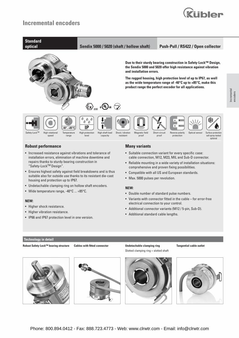
Due to their sturdy bearing construction in Safety-Lock™ Design, the Sendix 5000 and 5020 offer high resistance against vibration and installation errors.
The rugged housing, high protection level of up to IP67, as well as the wide temperature range of -40°C up to +85°C, make this product range the perfect encoder for all applications.
Safety-LockTM High rotationalspeed
Temperaturerange
High protection level
High shaft loadcapacity
Shock / vibrationresistant
Magnetic fieldproof
Short-circuitproof
Reverse polarityprotection
Robust performance• Increased resistance against vibrations and tolerance of
installation errors, elimination of machine downtime and repairs thanks to sturdy bearing construction in “Safety-LockTM Design”.
• Ensures highest safety against field breakdowns and is thus suitable also for outside use thanks to its resistant die-cast housing and protection up to IP67.
• Undetachable clamping ring on hollow shaft encoders.• Wide temperature range, -40°C ... +85°C.
NEW:• Higher shock resistance.• Higher vibration resistance.• IP66 and IP67 protection level in one version.
Many variants• Suitable connection variant for every specific case:
cable connection, M12, M23, MIL and Sub-D connector.• Reliable mounting in a wide variety of installation situations:
comprehensive and proven fixing possibilities.• Compatible with all US and European standards.• Max. 5000 pulses per revolution.
NEW:• Double number of standard pulse numbers.• Variants with connector fitted in the cable – for error-free
electrical connection to your control.• Additional connector variants (M12 / 5-pin, Sub-D).• Additional standard cable lengths.
Technology in detail
Undetachable clamping ring
Slotted clamping ring + slotted shaft
Cables with fitted connectorRobust Safety-Lock™ bearing structure Tangential cable outlet
Phone: 800.894.0412 - Fax: 888.723.4773 - Web: www.clrwtr.com - Email: [email protected]

Order codeShaft version
8.5000Type
. X X X X . XXXXa b c d e
Incremental encoders
Push-Pull / RS422 / Open collectorStandardoptical Sendix 5000 / 5020 (shaft / hollow shaft)
a Flange 5 = synchro flange, IP66/IP67 ø 50.8 mm [2“] 6 = synchro flange, IP65 ø 50.8 mm [2“] 7 = clamping flange, IP66/IP67 ø 58 mm [2.28“] 8 = clamping flange, IP65 ø 58 mm [2.28“] A = synchro flange, IP66/IP67 ø 58 mm [2.28“] B = synchro flange, IP65 ø 58 mm [2.28“] C = square flange, IP66/IP67 63.5 mm [2.5“] D = square flange, IP65 63.5 mm [2.5“] G = Euroflansch, IP66/IP67 ø 115 mm [4.53“] 1)
1 = servo flange, IP66/IP67 ø 50.8 mm [2“] 2 = servo flange, IP65 ø 50.8 mm [2“] 3 = square flange, IP66/IP67 52.3 mm [2.06“] 4 = square flange, IP65 52.3 mm [2.06“] E = servo flange, IP66/IP67 ø 63.5 mm [2.5“] F = servo flange, IP65 ø 63.5 mm [2.5“]
b Shaft (ø x L), with flat 1 = ø 6 x 10 mm [0.24 x 0.39“] 2 = ø 1/4 x 5/8“ (6.35 x 15.875 mm) 6 = ø 8 x 15 mm [0.32 x 0.59“] 3 = ø 10 x 20 mm [0.39 x 0.79“] 4 = ø 3/8 x 5/8“(9.5 x 15.875 mm) B = ø 11 x 33 mm [0.43 x 1.30“], with feather key shaft slot 2)
5 = ø 12 x 20 mm [0.47 x 0.79“]
7 = ø 1/4 x 7/8“ 8 = ø 3/8 x 7/8“
c Output circuit / power supply 4 = RS422 (with inverted signal) / 5 V DC 1 = RS422 (with inverted signal) / 5 ... 30 V DC 2 = Push-Pull (7272 compatible with inverted signal) / 5 ... 30 V DC 5 = Push-Pull (with inverted signal) / 10 ... 30 V DC 7 = Push-Pull (without inverted signal) / 10 ... 30 V DC 3)
3 = Open collector (with inverted signal) / 5 ... 30 V DC 8 = Push-Pull (7272 with inverted signal), without capacitor / 5 ... 30 V DC 4)
d Type of connection – cable 1 = axial cable, 1 m [3.28‘] PVC A = axial cable, special length PVC *) 2 = radial cable, 1 m [3.28‘] PVC B = radial cable, special length PVC *)
Type of connection – connector P = axial M12 connector, 5-pin 5)
R = radial M12 connector, 5-pin 5)
3 = axial M12 connector, 8-pin 4 = radial M12 connector, 8-pin 7 = axial M23 connector, 12-pin 8 = radial M23 connector, 12-pin Y = radial MIL connector, 10-pin W = radial MIL connector, 7-pin
9 = radial MIL connector, 6-pin
Type of connection – connector with cable L = radial cable with M12 connector, 8-pin, special length PVC *) M = radial cable with M23 connector, 12-pin, special length PVC *) N = radial cable with Sub-D connector, 9-pin, special length PVC *)
*) Available special lengths (connection types A, B, L, M, N: 0.3, 0.5, 1, 2, 3, 4, 5, 6, 8, 10, 12, 15, 20 m [0.98, 1.64, 3.28, 6.56, 9.84,
13.12, 16.40, 19,69, 26.25, 32.80, 39.37, 49.21, 65,62‘]order code expansion .XXXX = length in dm
ex.: 8.5000.814A.1024.0030 (for cable length 3 m)
e Pulse rate1, 2, 4, 5, 10, 12, 14, 20, 25, 28, 30, 32, 36, 50, 60, 64, 80, 100, 120, 125,150, 180, 200, 240, 250, 256, 300, 342, 360, 375, 400, 500, 512, 600,625, 720, 800, 900, 1000, 1024, 1200, 1250, 1500, 1800, 2000, 2048,2500, 3000, 3600, 4000, 4096, 5000(e.g. 100 pulses => 0100)
f Special output signal formats00 = standard output other = see page 8
g Capacitor 0 = standard A = no bypass capacitor (vector motor)
(only valide with output circuits 1, 3, 4, 5)
h Special connector pin configuration 0 = standard wiring other = see page 6
Optional on request- other pulse rates- Ex 2/22 6)
- surface protection salt spray
1) Only in conjunction with shaft type B.2) Only in conjunction with flange type G.3) Only in conjunction with type of connection P or R.
4) Attention: no CE types!5) Only in conjunction with output circuit 7.6) For the cable connection type, cable material PUR.
. P XX X Xf g h
Phone: 800.894.0412 - Fax: 888.723.4773 - Web: www.clrwtr.com - Email: [email protected]
Incr
emen
tal
enco
ders
Incremental encoders
Push-Pull / RS422 / Open collectorStandardoptical Sendix 5000 / 5020 (shaft / hollow shaft)
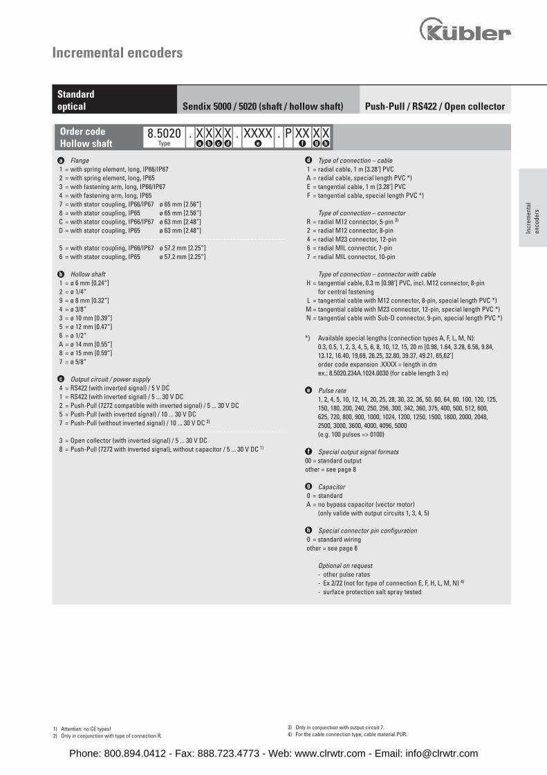
a Flange 1 = with spring element, long, IP66/IP67 2 = with spring element, long, IP65 3 = with fastening arm, long, IP66/IP67 4 = with fastening arm, long, IP65 7 = with stator coupling, IP66/IP67 ø 65 mm [2.56“] 8 = with stator coupling, IP65 ø 65 mm [2.56“] C = with stator coupling, IP66/IP67 ø 63 mm [2.48“] D = with stator coupling, IP65 ø 63 mm [2.48“]
5 = with stator coupling, IP66/IP67 ø 57.2 mm [2.25“] 6 = with stator coupling, IP65 ø 57.2 mm [2.25“]
b Hollow shaft 1 = ø 6 mm [0.24“] 2 = ø 1/4“ 9 = ø 8 mm [0.32“] 4 = ø 3/8“ 3 = ø 10 mm [0.39“] 5 = ø 12 mm [0.47“] 6 = ø 1/2“ A = ø 14 mm [0.55“] 8 = ø 15 mm [0.59“] 7 = ø 5/8“
c Output circuit / power supply 4 = RS422 (with inverted signal) / 5 V DC 1 = RS422 (with inverted signal) / 5 ... 30 V DC 2 = Push-Pull (7272 compatible with inverted signal) / 5 ... 30 V DC 5 = Push-Pull (with inverted signal) / 10 ... 30 V DC 7 = Push-Pull (without inverted signal) / 10 ... 30 V DC 2)
3 = Open collector (with inverted signal) / 5 ... 30 V DC 8 = Push-Pull (7272 with inverted signal), without capacitor / 5 ... 30 V DC 1)
d Type of connection – cable 1 = radial cable, 1 m [3.28‘] PVC A = radial cable, special length PVC *) E = tangential cable, 1 m [3.28‘] PVC F = tangential cable, special length PVC *)
Type of connection – connector R = radial M12 connector, 5-pin 3)
2 = radial M12 connector, 8-pin 4 = radial M23 connector, 12-pin 6 = radial MIL connector, 7-pin 7 = radial MIL connector, 10-pin
Type of connection – connector with cable H = tangential cable, 0.3 m [0.98‘] PVC, incl. M12 connector, 8-pin
for central fastening L = tangential cable with M12 connector, 8-pin, special length PVC *) M = tangential cable with M23 connector, 12-pin, special length PVC *) N = tangential cable with Sub-D connector, 9-pin, special length PVC *)
*) Available special lengths (connection types A, F, L, M, N): 0.3, 0.5, 1, 2, 3, 4, 5, 6, 8, 10, 12, 15, 20 m [0.98, 1.64, 3.28, 6.56, 9.84,
13.12, 16.40, 19,69, 26.25, 32.80, 39.37, 49.21, 65,62‘]order code expansion .XXXX = length in dm
ex.: 8.5020.234A.1024.0030 (for cable length 3 m)
e Pulse rate1, 2, 4, 5, 10, 12, 14, 20, 25, 28, 30, 32, 36, 50, 60, 64, 80, 100, 120, 125,150, 180, 200, 240, 250, 256, 300, 342, 360, 375, 400, 500, 512, 600,625, 720, 800, 900, 1000, 1024, 1200, 1250, 1500, 1800, 2000, 2048,2500, 3000, 3600, 4000, 4096, 5000(e.g. 100 pulses => 0100)
f Special output signal formats00 = standard output other = see page 8
g Capacitor 0 = standard A = no bypass capacitor (vector motor)
(only valide with output circuits 1, 3, 4, 5)
h Special connector pin configuration 0 = standard wiring other = see page 6
Optional on request- other pulse rates- Ex 2/22 (not for type of connection E, F, H, L, M, N) 4)
- surface protection salt spray tested
Order codeHollow shaft
8.5020 . X X X X . XXXXType a b c d e
1) Attention: no CE types!2) Only in conjunction with type of connection R.
3) Only in conjunction with output circuit 7.4) For the cable connection type, cable material PUR.
. P XX X Xf g h
Phone: 800.894.0412 - Fax: 888.723.4773 - Web: www.clrwtr.com - Email: [email protected]
Incremental encoders
Connection technology Order no.
Connector, self-assembly (straight) M12 female connector with coupling nut 05.CMB 8181-0
M23 female connector with coupling nut 8.0000.5012.0000
MIL female connector with coupling nut, 10-pin 8.0000.5062.0000
Cordset, pre-assembled M12 female connector with coupling nut, 2 m [6.56‘] PVC cable 05.00.6041.8211.002M
M23 female connector with coupling nut, 2 m [6.56‘] PVC cabl 8.0000.6901.0002
Additional connectors can be found in the connection technology section or in the connection technology area of our website.
Push-Pull / RS422 / Open collectorStandardoptical Sendix 5000 / 5020 (shaft / hollow shaft)
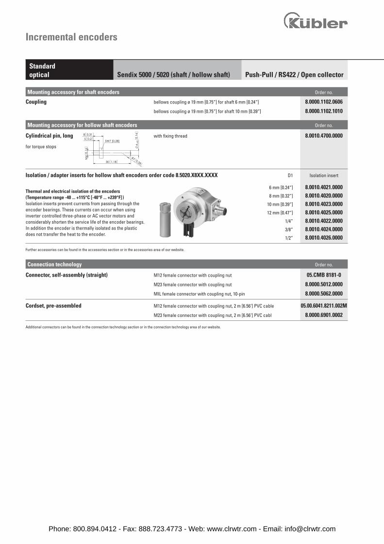
Mounting accessory for shaft encoders Order no.
Coupling bellows coupling ø 19 mm [0.75“] for shaft 6 mm [0.24“] 8.0000.1102.0606
bellows coupling ø 19 mm [0.75“] for shaft 10 mm [0.39“] 8.0000.1102.1010
SW7 [0,28]0,25
8 0,31
0,16
0,287
m8
4
M4 R
30 1,18
0,16
Mounting accessory for hollow shaft encoders Order no.
Cylindrical pin, long with fixing thread 8.0010.4700.0000
for torque stops
Isolation / adapter inserts for hollow shaft encoders order code 8.5020.X8XX.XXXX D1 Isolation insert
6 mm [0.24“] 8.0010.4021.0000 8 mm [0.32“] 8.0010.4020.0000 10 mm [0.39“] 8.0010.4023.0000
12 mm [0.47“] 8.0010.4025.0000 1/4“ 8.0010.4022.0000 3/8“ 8.0010.4024.0000
1/2“ 8.0010.4026.0000
Further accessories can be found in the accessories section or in the accessories area of our website.
Thermal and electrical isolation of the encoders(Temperature range -40 ... +115°C [-40°F ... +239°F] )Isolation inserts prevent currents from passing through the encoder bearings. These currents can occur when using inverter controlled three-phase or AC vector motors and considerably shorten the service life of the encoder bearings. In addition the encoder is thermally isolated as the plastic does not transfer the heat to the encoder.
Phone: 800.894.0412 - Fax: 888.723.4773 - Web: www.clrwtr.com - Email: [email protected]
Incr
emen
tal
enco
ders
Incremental encoders
Push-Pull / RS422 / Open collectorStandardoptical Sendix 5000 / 5020 (shaft / hollow shaft)
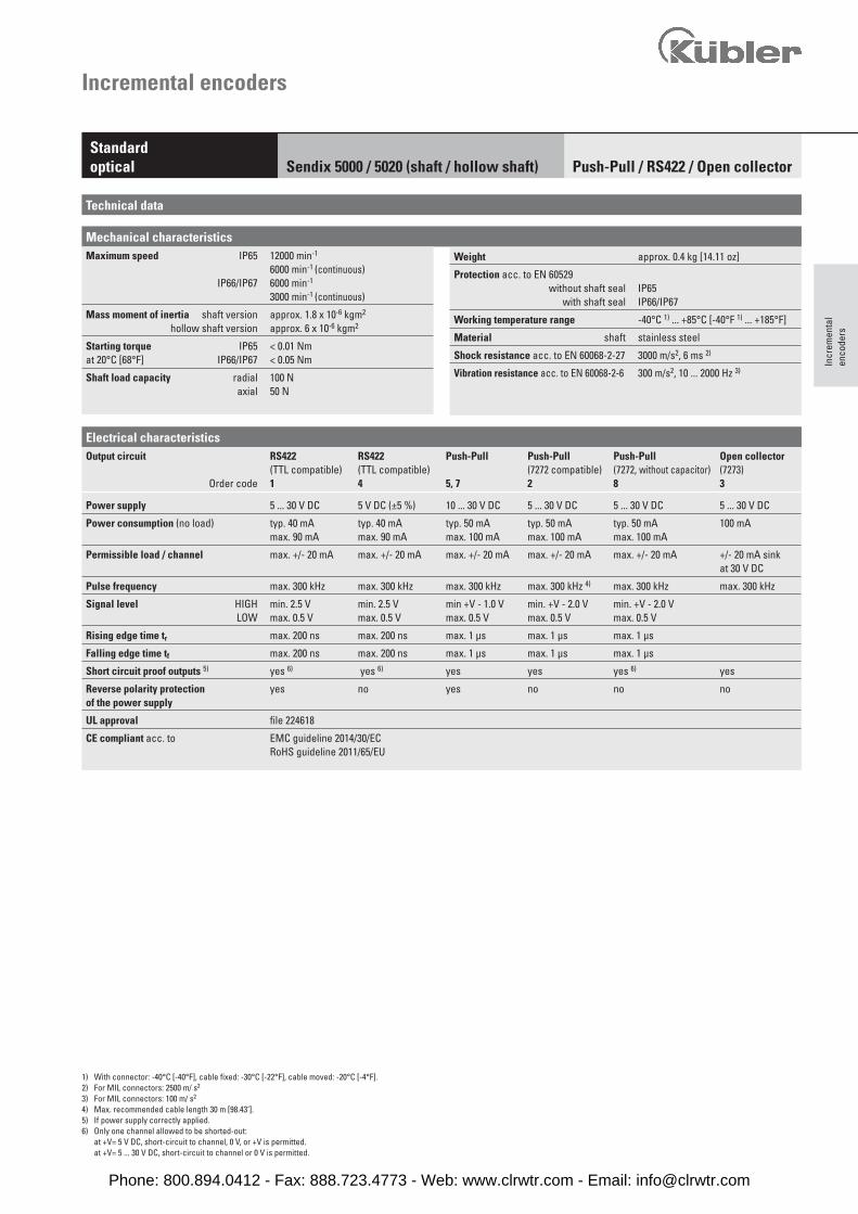
Mechanical characteristics
Technical data
Maximum speed IP65 12000 min-1
6000 min-1 (continuous)IP66/IP67 6000 min-1
3000 min-1 (continuous)
Mass moment of inertia shaft version approx. 1.8 x 10⁻⁶ kgm2 hollow shaft version approx. 6 x 10⁻⁶ kgm2
Starting torque IP65 < 0.01 Nm at 20°C [68°F] IP66/IP67 < 0.05 Nm
Shaft load capacity radial 100 N axial 50 N
Electrical characteristicsOutput circuit RS422 RS422 Push-Pull Push-Pull Push-Pull Open collector
(TTL compatible) (TTL compatible) (7272 compatible) (7272, without capacitor) (7273) Order code 1 4 5, 7 2 8 3
Power supply 5 ... 30 V DC 5 V DC (±5 %) 10 ... 30 V DC 5 ... 30 V DC 5 ... 30 V DC 5 ... 30 V DC
Power consumption (no load) typ. 40 mA typ. 40 mA typ. 50 mA typ. 50 mA typ. 50 mA 100 mA max. 90 mA max. 90 mA max. 100 mA max. 100 mA max. 100 mA
Permissible load / channel max. +/- 20 mA max. +/- 20 mA max. +/- 20 mA max. +/- 20 mA max. +/- 20 mA +/- 20 mA sink at 30 V DC
Pulse frequency max. 300 kHz max. 300 kHz max. 300 kHz max. 300 kHz 4) max. 300 kHz max. 300 kHz
Signal level HIGH min. 2.5 V min. 2.5 V min +V - 1.0 V min. +V - 2.0 V min. +V - 2.0 VLOW max. 0.5 V max. 0.5 V max. 0.5 V max. 0.5 V max. 0.5 V
Rising edge time tr max. 200 ns max. 200 ns max. 1 μs max. 1 μs max. 1 μs
Falling edge time tf max. 200 ns max. 200 ns max. 1 μs max. 1 μs max. 1 μs
Short circuit proof outputs 5) yes 6) yes 6) yes yes yes 6) yes
Reverse polarity protection yes no yes no no no of the power supply
UL approval file 224618
CE compliant acc. to EMC guideline 2014/30/EC RoHS guideline 2011/65/EU
1) With connector: -40°C [-40°F], cable fixed: -30°C [-22°F], cable moved: -20°C [-4°F].2) For MIL connectors: 2500 m/ s2
3) For MIL connectors: 100 m/ s2
4) Max. recommended cable length 30 m [98.43‘].5) If power supply correctly applied.6) Only one channel allowed to be shorted-out:
at +V= 5 V DC, short-circuit to channel, 0 V, or +V is permitted.at +V= 5 ... 30 V DC, short-circuit to channel or 0 V is permitted.
Weight approx. 0.4 kg [14.11 oz]
Protection acc. to EN 60529 without shaft seal IP65
with shaft seal IP66/IP67
Working temperature range -40°C 1) ... +85°C [-40°F 1) ... +185°F]
Material shaft stainless steel
Shock resistance acc. to EN 60068-2-27 3000 m/s2, 6 ms 2)
Vibration resistance acc. to EN 60068-2-6 300 m/s2, 10 ... 2000 Hz 3)
Phone: 800.894.0412 - Fax: 888.723.4773 - Web: www.clrwtr.com - Email: [email protected]
Incremental encoders
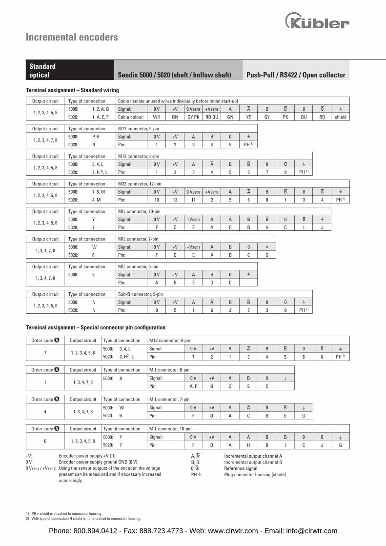
Output circuit Type of connection Cable (isolate unused wires individually before initial start-up)
5000: 1, 2, A, B Signal: 0 V +V 0 Vsens +Vsens A B 0 H1, 2, 3, 4, 5, 8
5020: 1, A, E, F Cable colour: WH BN GY PK RD BU GN YE GY PK BU RD shield
Output circuit Type of connection M12 connector, 8-pin
5000: 3, 4, L Signal: 0 V +V A B 0 H1, 2, 3, 4, 5, 8
5020: 2, H 2), L Pin: 1 2 3 4 5 6 7 8 PH 1)
Output circuit Type of connection M12 connector, 5-pin
5000: P, R Signal: 0 V +V A B 0 H1, 2, 3, 4, 7, 8
5020: R Pin: 1 2 3 4 5 PH 1)
Output circuit Type of connection M23 connector, 12-pin
5000: 7, 8, M Signal: 0 V +V 0 Vsens +Vsens A B 0 H1, 2, 3, 4, 5, 8
5020: 4, M Pin: 10 12 11 2 5 6 8 1 3 4 PH 1)
Output circuit Type of connection MIL connector, 7-pin
5000: W Signal: 0 V +V +Vsens A B 0 H1, 3, 4, 7, 8
5020: 6 Pin: F D E A B C G
Output circuit Type of connection MIL connector, 10-pin
5000: Y Signal: 0 V +V +Vsens A B 0 H1, 2, 3, 4, 5, 8
5020: 7 Pin: F D E A G B H C I J
Output circuit Type of connection MIL connector, 6-pin
5000: 9 Signal: 0 V +V A B 0 H1, 3, 4, 7, 8
Pin: A B E D C
Output circuit Type of connection Sub-D connector, 9-pin
5000: N Signal: 0 V +V A B 0 H1, 2, 3, 4, 5, 8
5020: N Pin: 9 5 1 6 2 7 3 8 PH 1)
1) PH = shield is attached to connector housing.2) With type of connection H shield is not attached to connector housing.
Terminal assignment – Standard wiring
Terminal assignment – Special connector pin configuration
+V: Encoder power supply +V DC0 V: Encoder power supply ground GND (0 V)0 Vsens / +Vsens: Using the sensor outputs of the encoder, the voltage
present can be measured and if necessary increased accordingly.
A, : Incremental output channel AB, : Incremental output channel B0, : Reference signalPH H: Plug connector housing (shield)
Push-Pull / RS422 / Open collectorStandardoptical Sendix 5000 / 5020 (shaft / hollow shaft)
Order code h Output circuit Type of connection M12 connector, 8-pin
7 1, 2, 3, 4, 5, 85000: 3, 4, L
5020: 2, H2), L
Signal: 0 V +V A B 0 HPin: 7 2 1 3 4 5 6 8 PH 1)
Order code h Output circuit Type of connection MIL connector, 6-pin
1 1, 3, 4, 7, 85000: 9 Signal: 0 V +V A B 0 H
Pin: A, F B D E C
Order code h Output circuit Type of connection MIL connector, 7-pin
4 1, 3, 4, 7, 85000: W
5020: 6
Signal: 0 V +V A B HPin: F D A C B E G
Order code h Output circuit Type of connection MIL connector, 10-pin
6 1, 2, 3, 4, 5, 85000: Y
5020: 7
Signal: 0 V +V A B 0 HPin: F D A H B I C J G
Phone: 800.894.0412 - Fax: 888.723.4773 - Web: www.clrwtr.com - Email: [email protected]
Incr
emen
tal
enco
ders
Incremental encoders
Push-Pull / RS422 / Open collectorStandardoptical Sendix 5000 / 5020 (shaft / hollow shaft)
85 7
34 1
2
611
1
2
3
4 56
7
89
10 12
AB
CD
E
AB
CDE
F
GH
IJ
AB
CD
E
FG F
AB
CD
E
AB
CDE
F
GH
IJ
AB
CD
E
FG F
AB
CD
E
AB
CDE
F
GH
IJ
AB
CD
E
FG F
53 1
2
4
(1)
(6) (7) (8) (9)
(2) (3) (4) (5)
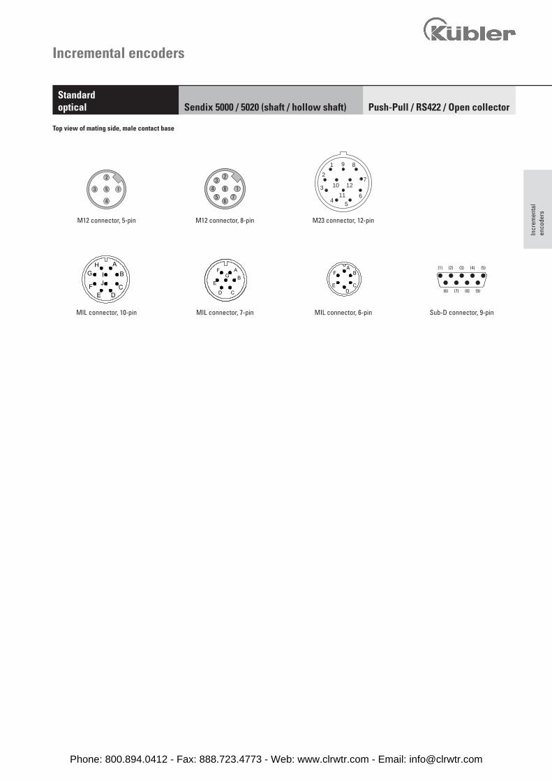
MIL connector, 10-pin MIL connector, 6-pinMIL connector, 7-pin Sub-D connector, 9-pin
Top view of mating side, male contact base
M12 connector, 8-pinM12 connector, 5-pin M23 connector, 12-pin
Phone: 800.894.0412 - Fax: 888.723.4773 - Web: www.clrwtr.com - Email: [email protected]
Incremental encoders
Push-Pull / RS422 / Open collectorStandardoptical Sendix 5000 / 5020 (shaft / hollow shaft)
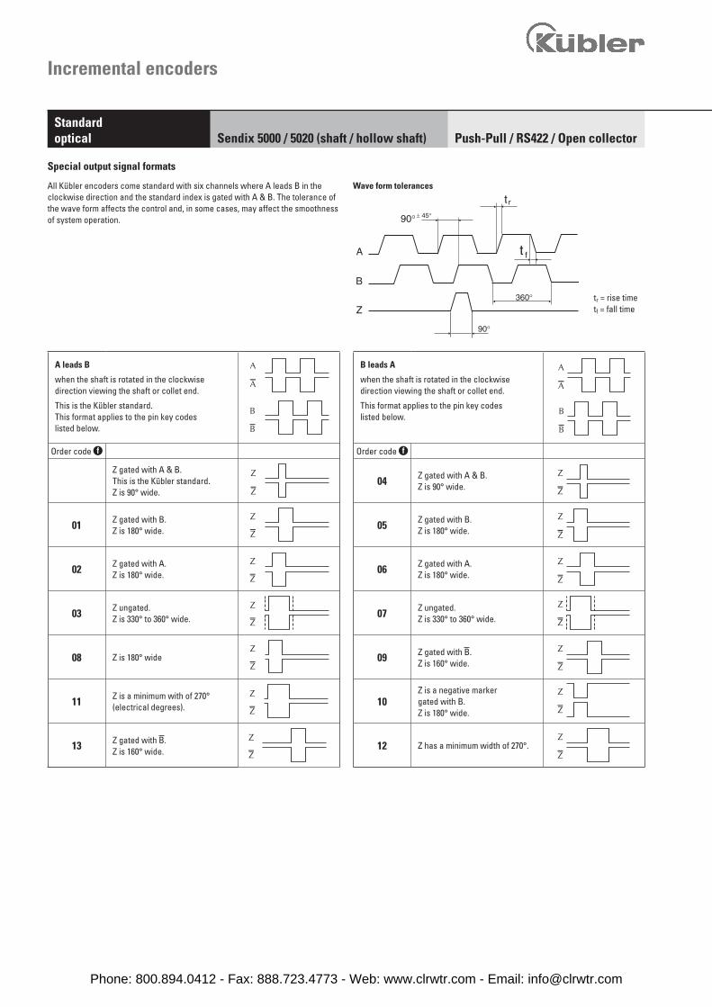
Special output signal formats
All Kübler encoders come standard with six channels where A leads B in the clockwise direction and the standard index is gated with A & B. The tolerance of the wave form affects the control and, in some cases, may affect the smoothness of system operation.
tr = rise timetf = fall time
Wave form tolerances
A leads B
when the shaft is rotated in the clockwisedirection viewing the shaft or collet end.
This is the Kübler standard. This format applies to the pin key codeslisted below.
Order code f
Z gated with A & B.This is the Kübler standard. Z is 90° wide.
01 Z gated with B.Z is 180° wide.
02 Z gated with A.Z is 180° wide.
03 Z ungated.Z is 330° to 360° wide.
08 Z is 180° wide
11 Z is a minimum with of 270°(electrical degrees).
13 Z gated with .Z is 160° wide.
B leads A
when the shaft is rotated in the clockwisedirection viewing the shaft or collet end.
This format applies to the pin key codeslisted below.
Order code f
04 Z gated with A & B.Z is 90° wide.
05 Z gated with B.Z is 180° wide.
06 Z gated with A.Z is 180° wide.
07 Z ungated.Z is 330° to 360° wide.
09 Z gated with .Z is 160° wide.
10Z is a negative marker gated with B. Z is 180° wide.
12 Z has a minimum width of 270°.
Phone: 800.894.0412 - Fax: 888.723.4773 - Web: www.clrwtr.com - Email: [email protected]
3x120°
40 1,57
1,3935,2
2,0953,2
2,81
71,4
90,4
3,56
1
2,81
2,26
3
L
3
71,4
0,12
0,13
43,7 1,72
57,4
47 1,85
1,84
h7
4730
250
,8
30,45
0,12
1,85
1,2
46,7
3,3
64 2,52
D
1,18
3x120°
421,
65
943,
7
2,2256,5
2,95
75
38,5 1,52
1
[1,9
7]
1,33
max
.50
0,16
0,123
0,123
33,75
2,28
0,83
58
D
L
1,97
50 h7
max.21
4
47 1,85
3x120°
481,
89[1,4
2]
50
21
23,8
1,97
0,83
L
0,39 1,46
D
582,
28
0,94
3710
36 f8
1
1,5238,5
3,7
942,95
750,3910
46,5 1,83
3x120°
481,
89[1,4
2]
50
21
23,8
1,97
0,83
L
0,39 1,46
D
582,
28
0,94
3710
36 f8
1
1,5238,5
3,7
942,95
75
0,3910
46,5 1,83
3x120°
481,
89[1,4
2]
50
21
23,8
1,97
0,83
L
0,39 1,46
D
582,
28
0,94
3710
36 f8
1
1,5238,5
3,7
942,95
75
0,3910
46,5 1,83
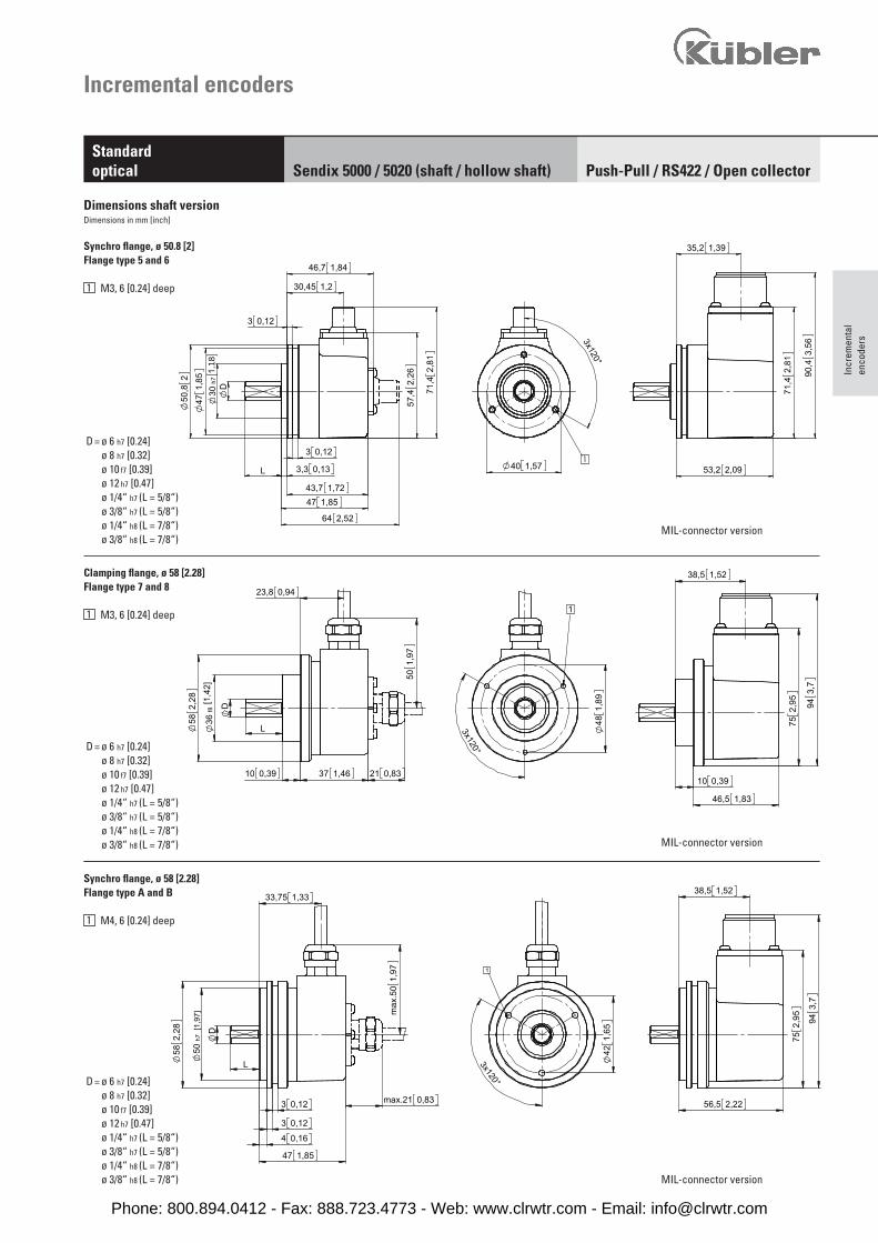
D = ø 6 h7 [0.24]ø 8 h7 [0.32]ø 10 f7 [0.39]ø 12 h7 [0.47]ø 1/4“ h7 (L = 5/8“)ø 3/8“ h7 (L = 5/8“)ø 1/4“ h8 (L = 7/8“)ø 3/8“ h8 (L = 7/8“)
D = ø 6 h7 [0.24]ø 8 h7 [0.32]ø 10 f7 [0.39]ø 12 h7 [0.47]ø 1/4“ h7 (L = 5/8“)ø 3/8“ h7 (L = 5/8“)ø 1/4“ h8 (L = 7/8“)ø 3/8“ h8 (L = 7/8“)
D = ø 6 h7 [0.24]ø 8 h7 [0.32]ø 10 f7 [0.39]ø 12 h7 [0.47]ø 1/4“ h7 (L = 5/8“)ø 3/8“ h7 (L = 5/8“)ø 1/4“ h8 (L = 7/8“)ø 3/8“ h8 (L = 7/8“)
Incr
emen
tal
enco
ders
Incremental encoders
Synchro flange, ø 50.8 [2] Flange type 5 and 6
1 M3, 6 [0.24] deep
Dimensions shaft versionDimensions in mm [inch]
Synchro flange, ø 58 [2.28]Flange type A and B
1 M4, 6 [0.24] deep
MIL-connector version
MIL-connector version
MIL-connector version
Clamping flange, ø 58 [2.28]Flange type 7 and 8
1 M3, 6 [0.24] deep
Push-Pull / RS422 / Open collectorStandardoptical Sendix 5000 / 5020 (shaft / hollow shaft)
Phone: 800.894.0412 - Fax: 888.723.4773 - Web: www.clrwtr.com - Email: [email protected]
[3,94]
115 4,53±0,1100
6,6
0,26
6x60°
85h5
61,6
33 1,3k611
2,43
8
1,4236
1,2231
50,8
0,31
0,123
4
2
0,16
582,
28
54,6
2,15
0,26
6,6
6 0,24
16 0,630,28
100,
39
7
13,25 0,52
[3,3
5]
1
[0,4
3]
1
[1,25]
1,03
7,5
2,5
7,1
63,5
1,97
39,5 1,56
D
31,7
5 h7
L
0,8321
0,28
0,3
26,25
max
.50
50,8
2 2,06
52,4
5,50,2
2
0,3
96,7
5
1,9349
3,06
77,7
5
3,81
7,5
31 1,22
[1,25]
1,03
7,5
2,5
7,1
63,5
1,97
39,5 1,56
D
31,7
5 h7
L
0,8321
0,28
0,3
26,25
max
.50
50,8
2 2,06
52,4
5,50,2
2
0,3
96,7
5
1,9349
3,06
77,7
5
3,81
7,5
31 1,22
Incremental encoders
Push-Pull / RS422 / Open collectorStandardoptical Sendix 5000 / 5020 (shaft / hollow shaft)
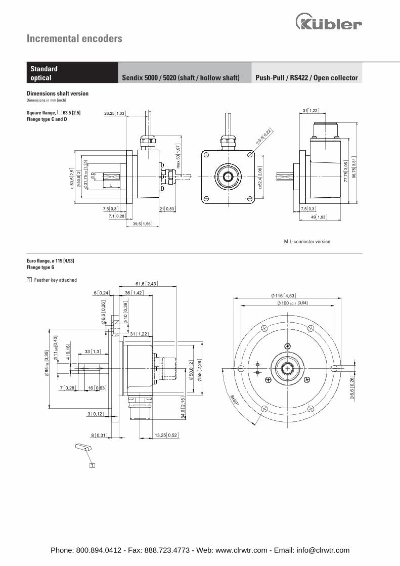
Dimensions shaft versionDimensions in mm [inch]
MIL-connector version
Square flange, 63.5 [2.5]Flange type C and D
Euro flange, ø 115 [4.53]Flange type G
1 Feather key attached
Phone: 800.894.0412 - Fax: 888.723.4773 - Web: www.clrwtr.com - Email: [email protected]
45°
3x120°
4x90°
1,6341,338,1 1,5
1
2
[1,2
5]
L
46
1,85
0,52
h7
13,25
31,7
5
47
1,81
0,1
D 2
2,540,1
50,8
2,54
60,7 2,39
0,133,3
43,7 1,72
1,3935,2
0,13
2,84
72,1
5 91,1
53,
59
3,353,2 2,09
45°
3x120° 4x90°
1,6341,338,1 1,5
1
2
[1,2
5]
L46
1,85
0,52
h7
13,25
31,7
5
47
1,81
0,1
D 2
2,540,1
50,8
2,54
60,7 2,39
0,133,3
43,7 1,72
1,3935,2
0,13
2,84
72,1
5 91,1
53,
59
3,353,2 2,09
45°
3x120°
4x90°
1,6341,338,1 1,5
1
2
[1,2
5]
L 46
1,85
0,52
h7
13,25
31,7
5
47
1,81
0,1
D 2
2,540,1
50,8
2,54
60,7 2,39
0,133,3
43,7 1,72
1,3935,2
0,13
2,84
72,1
5 91,1
53,
59
3,353,2 2,09
50,8 2
1
2
52,3
2,06
44,4
51,
75[1,2
5]
0,52
1,97
max
.50
0,83max.21
D
43,7
0,133,30,3
1,72
7,7
13,25
31,7
5 h7
L
0,132,
8472
,15
3,59
91,1
5
35,2 1,39
3,353,2 2,09
50,8 2
1
2
52,3
2,06
44,4
51,
75[1,2
5]
0,52
1,97
max
.50
0,83max.21
D
43,7
0,133,30,3
1,72
7,7
13,25
31,7
5 h7
L
0,13
2,84
72,1
5
3,59
91,1
5
35,2 1,39
3,353,2 2,09
50,8 2
1
2
52,3
2,06
44,4
51,
75[1,2
5]
0,52
1,97
max
.50
0,83max.21
D
43,7
0,133,30,3
1,72
7,7
13,25
31,7
5 h7
L
0,13
2,84
72,1
5
3,59
91,1
5
35,2 1,39
3,353,2 2,09
1,88
47,6
3
3x120°
[1,2
5]
58,8
72,
32
h731
,75
39,5
1,81
0,52
2,65 0,10,1
D
46
13,25
7,5 0,3
63,5
L
2,5
1,56
2,65
56,5 2,22
49 1,93
3,06
77,7
5
96,7
53,
81
0,37,5
31 1,22
1 1,88
47,6
3
3x120°
[1,2
5]
58,8
72,
32
h731
,75
39,5
1,81
0,52
2,65 0,10,1
D
46
13,25
7,5 0,3
63,5
L
2,5
1,56
2,65
56,5 2,22
49 1,93
3,06
77,7
5
96,7
53,
81
0,37,5
31 1,22
1 1,88
47,6
3
3x120°
[1,2
5]
58,8
72,
32 h7
31,7
5
39,5
1,81
0,52
2,65 0,10,1
D
46
13,25
7,5 0,3
63,5
L
2,5
1,56
2,65
56,5 2,22
49 1,93
3,06
77,7
5
96,7
53,
81
0,37,5
31 1,22
1
D = ø 6 h7 [0.24]ø 8 h7 [0.32]ø 10 f7 [0.39]ø 12 h7 [0.47]ø 1/4“ h7 (L = 5/8“)ø 3/8“ h7 (L = 5/8“)ø 1/4“ h8 (L = 7/8“)ø 3/8“ h8 (L = 7/8“)
D = ø 6 h7 [0.24]ø 8 h7 [0.32]ø 10 f7 [0.39]ø 12 h7 [0.47]ø 1/4“ h7 (L = 5/8“)ø 3/8“ h7 (L = 5/8“)ø 1/4“ h8 (L = 7/8“)ø 3/8“ h8 (L = 7/8“)
D = ø 6 h7 [0.24]ø 8 h7 [0.32]ø 10 f7 [0.39]ø 12 h7 [0.47]ø 1/4“ h7 (L = 5/8“)ø 3/8“ h7 (L = 5/8“)ø 1/4“ h8 (L = 7/8“)ø 3/8“ h8 (L = 7/8“)
Incr
emen
tal
enco
ders
Incremental encoders
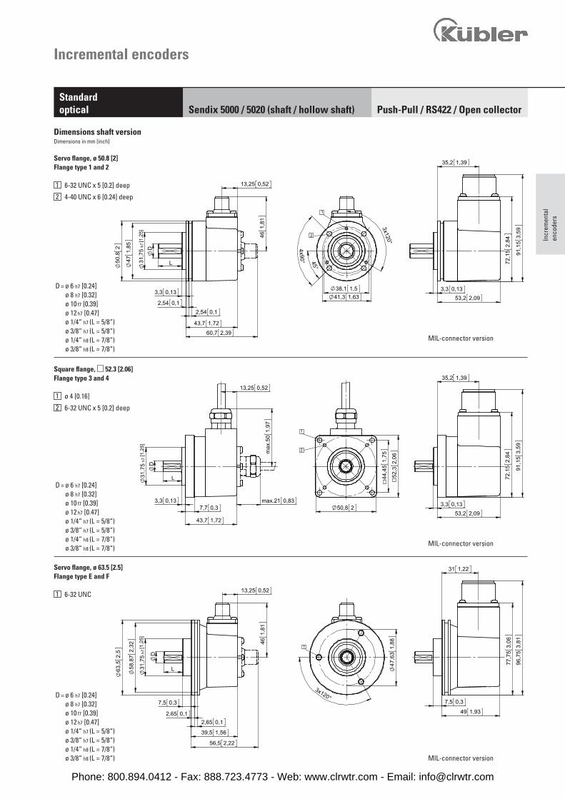
Servo flange, ø 50.8 [2] Flange type 1 and 2
1 6-32 UNC x 5 [0.2] deep
2 4-40 UNC x 6 [0.24] deep
Square flange, 52.3 [2.06] Flange type 3 and 4
1 ø 4 [0.16]
2 6-32 UNC x 5 [0.2] deep
Servo flange, ø 63.5 [2.5] Flange type E and F
1 6-32 UNC
Dimensions shaft versionDimensions in mm [inch]
MIL-connector version
MIL-connector version
MIL-connector version
Push-Pull / RS422 / Open collectorStandardoptical Sendix 5000 / 5020 (shaft / hollow shaft)
Phone: 800.894.0412 - Fax: 888.723.4773 - Web: www.clrwtr.com - Email: [email protected]
3x12
0°
42 1,65
33,7 1,33
1
2
[0,1
6]
37,9
0,09 3
,99
1,49
-0,0
2
0,55
2,414
D H7 3
1,25
31,7
5 33
250
,8
0,8221
1,81
46
1,26
32
1,3534,2
1,4837,5
1,3
max
.
45,1 1,78
90,4
3,56
36,2 1,43
43,7 1,72
2,81
71,4
54,2 2,13
50,2
1 1,5740
2,95753,3986
0,45
11,4
220,87
Incremental encoders
Push-Pull / RS422 / Open collectorStandardoptical Sendix 5000 / 5020 (shaft / hollow shaft)
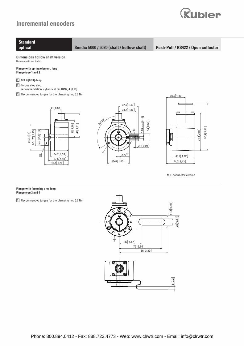
Flange with spring element, long Flange type 1 and 2
1 M3, 6 [0.24] deep
2 Torque stop slot, recommendation: cylindrical pin DIN7, 4 [0.16]
3 Recommended torque for the clamping ring 0.6 Nm
Flange with fastening arm, longFlange type 3 and 4
1 Recommended torque for the clamping ring 0.6 Nm
Dimensions hollow shaft versionDimensions in mm [inch]
MIL-connector version
Phone: 800.894.0412 - Fax: 888.723.4773 - Web: www.clrwtr.com - Email: [email protected]
25°
40°
632,
48
0,12
3,1
682,6
8
1
0,020,5
45,2 1,78
65 [2,56]
3x 1
20°
30°
57,15 2,25
31,5
1,24
54,6
2,15
DH7
3,2
0,13
1
50,2 [1.98]
50,8
[2.0
]
6,5 0,26
65 [2,56]
3x 1
20°
30°
37 [1
.46]
461,
81
1
50,2 [1.98]
50,8
[2.0
]
6,5 0,26
74 [2,91]
H7D
4,3 [0.17]
Incr
emen
tal
enco
ders
Incremental encoders
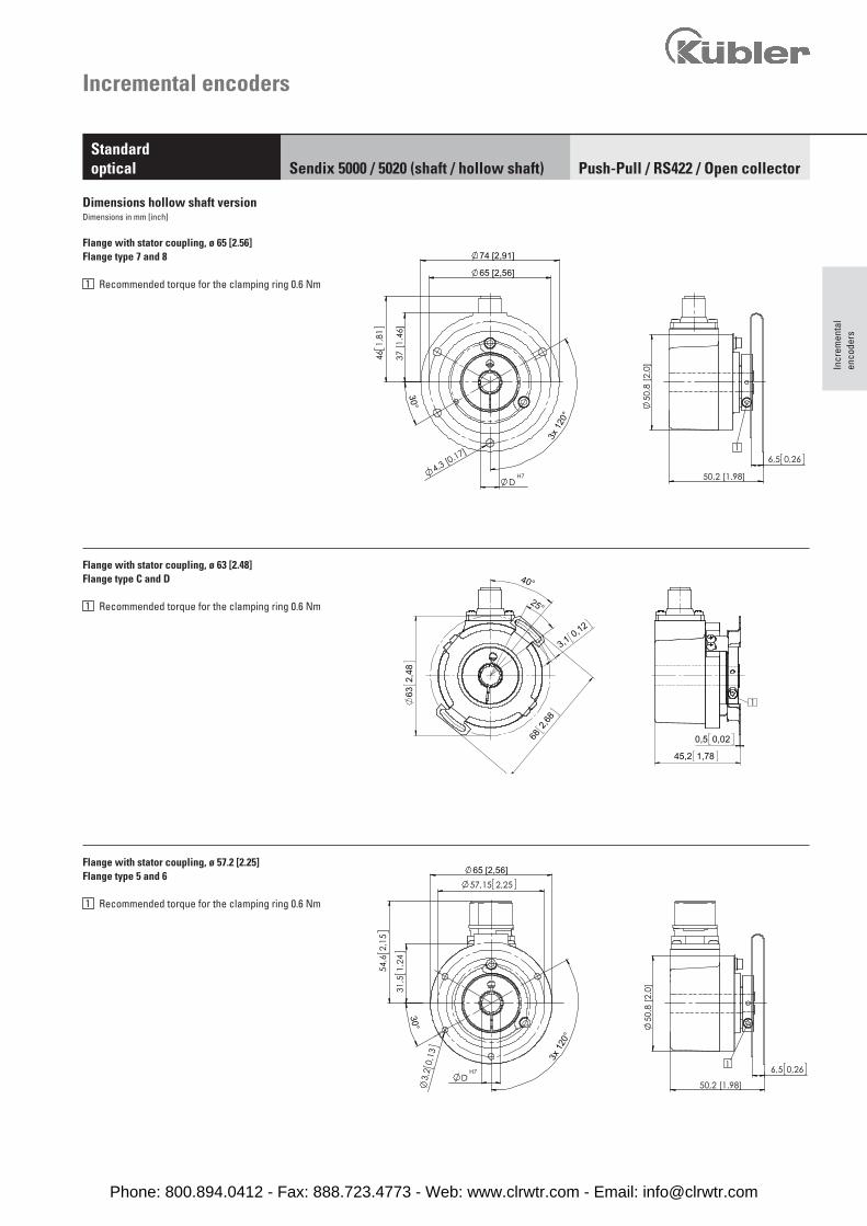
Flange with stator coupling, ø 63 [2.48]Flange type C and D
1 Recommended torque for the clamping ring 0.6 Nm
Flange with stator coupling, ø 57.2 [2.25]Flange type 5 and 6
1 Recommended torque for the clamping ring 0.6 Nm
Flange with stator coupling, ø 65 [2.56]Flange type 7 and 8
1 Recommended torque for the clamping ring 0.6 Nm
Dimensions hollow shaft versionDimensions in mm [inch]
Push-Pull / RS422 / Open collectorStandardoptical Sendix 5000 / 5020 (shaft / hollow shaft)
Phone: 800.894.0412 - Fax: 888.723.4773 - Web: www.clrwtr.com - Email: [email protected]
3x12
0°
33,7 [1.33]
42 [1.65]
M12
3
31,7
5 [1
.25]
50,8
[2.0
]
[1.54]39,1
33 [1
.3]
35,8 [1.41]
max
46,3 [1.82]
1
2
[1.49]
14
37,9
[0.09]2,4
3,99
[0.1
6] [0
.55]
DH7
Incremental encoders
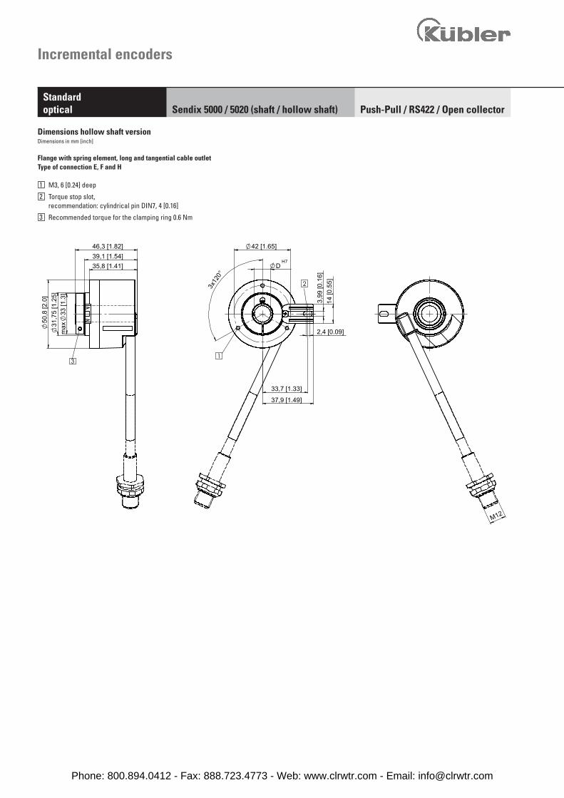
Push-Pull / RS422 / Open collectorStandardoptical Sendix 5000 / 5020 (shaft / hollow shaft)
Flange with spring element, long and tangential cable outletType of connection E, F and H
1 M3, 6 [0.24] deep
2 Torque stop slot, recommendation: cylindrical pin DIN7, 4 [0.16]
3 Recommended torque for the clamping ring 0.6 Nm
Dimensions hollow shaft versionDimensions in mm [inch]
Phone: 800.894.0412 - Fax: 888.723.4773 - Web: www.clrwtr.com - Email: [email protected]