![HDA Design anchor - Motek AS€¦ · Anchor bolt Nominal tensile strength f uk [N/mm²] 800 800 800 ... HDA Design anchor 09 / 2012 77 Anchor TE 24 a) TE 25 a) Anchor Anchor. HDA](https://static.fdocuments.net/doc/165x107/5b34310d7f8b9a436d8bbdfd/hda-design-anchor-motek-as-anchor-bolt-nominal-tensile-strength-f-uk-nmm.jpg)
KSN Anchor Brochure UK:-
24
KSN Anchors Reinforcement Continuity System for the Construction Industry CI/SfB (29) Et6 March 2013 Enhanced Performance Loads in Slab-to-Wall Moment Connections
Transcript of KSN Anchor Brochure UK:-

KSN Anchors Reinforcement Continuity Systemfor the Construction Industry
CI/SfB (29) Et6
March 2013
Enhanced Performance Loads in Slab-to-Wall Moment Connections

KSN AnchorsSafer, faster, easier construction joints
System Components,Details for Specifying and Ordering 4-5
System Performance,Bottom Anchorage Options 6-7
Key Design Considerations 8
Anchor Selection Examples 9
Direct Tensile Concrete Characteristic Loads 10-11
Tensile Concrete Characteristic Loads in Moment Connections 12-14
Design Considerations -Reinforcement Details, Bottom Anchor Design Guidance,Ductility Requirements, Corners, Shear Checks 15-19
Installation Procedure and Guidance on Cutting Anchor Carrier 20-22
Other Ancon Products 23
Contents
Ancon KSN Anchors, incombination with Bartec parallel-threaded reinforcing bars, simplifyconcrete construction joints.
Together, they allow engineers todesign slab-to-wall connectionswithout the restrictions on barlength and bar diameter of re-bend continuity systems or theawkward anchorage lengthsdemanded by reinforcing barcouplers.
KSN Anchors are cast into theconcrete wall and, when theformwork and thread protectionare removed, the reinforcing barsare simply screwed into theanchors.
This is a quicker, easier, andabove all safer continuity system.
It eliminates the drilling offormwork or concrete and thedangers associated withprojecting bars and on site barstraightening. It replaces hookedbars and stirrups, simplifying barscheduling and minimisingcongestion in the wall.
Unlike pull-out bar systems, thereis virtually no restriction oncontinuation bar length and theyare available in a greater choice ofbar diameters.
In addition to their suitability fordirect tensile applications,independent tests have verifiedan enhancement in theperformance of KSN Anchorswhen used in slab-to-wallmoment connections.
Traditional slab-to-wall construction jointDrilling of formwork required,projecting reinforcing bars andcongestion in the wall.
Re-bend continuity systemBox dimensions restrict barlength and diameter. On-sitebar straightening required.
Reinforcing bar couplersAwkward anchorage bars.Congestion in the wall. Noshear key. Individual couplerinstallation slows site progress.
2 Tel: +44 (0) 114 275 5224 www.ancon.co.uk
NEW high performance, KSN Anchor systemAnchors installed in a carrier.Indented construction joint.Virtually unlimited bar length.No bending of bars required.Less congestion in the wall.

3
Eliminates risksassociated with on-site
bar straightening
Virtually unlimitedcontinuation bar
length.Suitable for
EC2 lap lengths
Standard componentsfor ‘just-in-time’ sitedelivery, direct from
stock
Available up to a 20mm bar diameter.Rebend systems arerestricted to Ø16mm
Easy visual check ofcorrect bar
engagement
Simple to schedule.Fast to install
No torqueing required
Reduces reinforcementcongestion. Ideal for
thin walls
EC2 indentedconstruction joint
Enhanced performancebacked by test data
Winner
Best Product in Show 2013

Ancon KSN Anchors
KSN Tapered Timber Anchor CarrierKSN Anchors are delivered to site pre-assembled as independent rows of anchors fixed withcountersunk socket head cap screws to the back of a tapered timber strip.
The timber provides an additional 33mm of embedment to eachKSN Anchor and, after removal, provides a shear key for the joint. By increasing the embedment depth, the capacity of aKSN Anchor is improved.
The timber features one coloured side to denote the upward facingedge when orientating it against formwork and a product label to identify itas either a top or a bottom row of anchors. Tape is provided on the front of thestrip to protect the socket head from concrete ingress to facilitate easy removal. Aformwork release agent should be applied to the timber on site.
4 Tel: +44 (0) 114 275 5224 www.ancon.co.uk
Ancon KSN Anchors, in combination with Bartec parallel-threaded reinforcing bars, simplify concreteslab-to-wall construction joints when compared to other continuity systems.
This quicker, easier and above all, safer system eliminates the need for on-site bar straightening and thedrilling of formwork or concrete. The system replaces hooked anchorage bars and stirrups, therebysimplifying bar scheduling and minimising congestion in the wall. Suitable for wall thickness from 175mm.
Independent tests have verified enhancements in anchor performance in moment-resisting connections.This enhancement is specific to the KSN range.
ExternalDiameterMetric Thread
Head A/F Length
HeadWidth
Nominal Nominal NominalAnchor External Metric Head Head Anchor EmbedmentRef. Diameter Thread Width A/F Length heff
(mm) (mm) (mm) (mm) (mm) mm
KSN12S 22 M16 x 2.0 46 40 115 142KSN12M 150 177KSN16S 130 157KSN16M 28 M20 x 2.5 61 53 160 187KSN16L 190 217KSN20S 150 177KSN20M 32 M24 x 3.0 75 65 190 217KSN20L 230 257
KSN Anchor Dimensions
System Components
KSN AnchorsThere are eight standard anchors in the KSN range. They are manufactured from highly reliable Cr-Mo alloy steel with a minimum 15% elongation. The head is formed by hot forging to minimisematerial usage and improve the strength characteristics. The anchor is subsequently machined toincorporate a standard metric Bartec thread. Independent tests have verified the direct pull out strength of these anchors (see pages 10 to 11)and also quantified the enhancement in performance of KSN Anchors when used in slab-to-wallmoment connections (see pages 12 to 14).
6mm
33mm
heff Embedment Depth of Anchor
Anchor LengthFace ofConcrete
Tapered TimberAnchor Carrier
Anchor Embedment Arrangement
Tapered timber strips simplify installation,create a shear key and increase anchorembedment
KSN Anchors, eight standard sizesavailable from stock

Bartec Continuation BarsUnlike re-bend continuity systems where bar lengths are restricted to the box dimensions, there isvirtually no restriction on continuation bar length with KSN Anchors.
Ancon KSN Anchors are designed for use with 12mm, 16mm and 20mm diameter grade B500Bor B500C reinforcing bar, threaded with a Bartec metric thread, supplied by Ancon. The Bartecsystem produces a full strength joint. The bar end is cut square and enlarged by cold forging.This increases the core diameter of the threaded portion of the bar to ensure that the strength ofthe bar is maintained. A parallel metric thread is cut onto the enlarged bar end. A 12mm bar isprovided with an M16 thread, a 16mm bar with an M20 thread and a 20mm bar with an M24thread.
Bar lengths to BS EN 1992:1-1 (Eurocode 2) are given in the tables below.
Specifying and OrderingAn Ancon KSN Anchor system can be specified and ordered using the following identification method:Anchor Ref. / Horizontal Spacing (mm) / Anchor Position in Slab (TOP or BOTTOM) / Cover (mm)e.g. KSN16S / 200 / TOP / 25This is the reference for a KSN system comprising KSN16S anchors to be installed at 200mm horizontal spacing in the top of the slab, with 25mmcover to the reinforcement.
5
EC2 MinimumFull Tension Lap* Length L1 Required Minimum Minimum
C32/40 C32/40 Bar Length Bar LengthBar Thread Good Bad Good Bad Thread Required RequiredDiameter Size Bond Bond Bond Bond Length Good Bond Bad Bond
12 M16 630 890 688 948 16 705 96516 M20 830 1190 888 1248 20 910 127020 M24 1040 1480 1098 1538 24 1125 1565Dimensions in millimetres.*Assumes contact lap (a2=1) and 100% of bar lapped at one location.
MinimumEC2 Tension Length L2 Minimum
Bar Thread Lap* Required Thread Bar LengthDiameter Size C32/40 C32/40 Length Required
12 M16 630 688 16 70516 M20 830 888 20 91020 M24 1040 1098 24 1125Dimensions in millimetres.*Assumes contact lap (a2=1) and 100% of bar lapped at one location.
Top Reinforcement to Eurocode 2
Bottom Reinforcement to Eurocode 2
KSNAnchor
25mm Cover
Diameter
Diameter (01)
(01)
L2
L1
Slab
No on-site bar straightening required
12, 16, 20mm diameterBartec continuation bars,available in EC2 lap lengths
Slab reinforcement lappedto projecting rebars
Provide bottom bar,Mark (01) with Ushaped end
Projecting rebars withBartec threaded endto suit KSN Anchor
Refer to page 16 for bottom anchor designguidance.
Note: Good bond and bad bond conditions as defined in BS EN 1992-1-1 figure 8.2.

Ancon KSN Anchors
6 Tel: +44 (0) 114 275 5224 www.ancon.co.uk
T
Fig B. Reduced SpacingsFig A. Full Tensile Cone
heff
Approx.35˚
1.5heff
1.5heff
Characteristic loads as per the CEB Design of Fastenings in Concrete:N0
Rk,c = k1 . fck0.5 . heff
1.5
Where:
N0Rk,c is the tension resistance of a single anchor remote from edge effects
fck0.5 is the characteristic concrete cylinder compressive strength
heff is the embedment depth of the anchor
k1 is an empirical coefficient
k1 = 12.5
The equation becomes
Design resistance
N0Rd,c = k1 fck
0.5 . heff1.5/γm,c
with γm,c= 1.5 as per Eurocode 2.
Direct tensile concrete characteristic loads
The direct pull out strength of anchorsembedded in concrete has been the subject ofextensive research over many years. Todetermine the direct pull strength of KSNAnchors, Ancon commissioned a testprogramme at Heriot Watt University, UK. Thetest results and subsequent analysis alignedclosely with established formula for the pull outstrength of anchors. The direct pull outstrength is based on a model with a break outprism angle of approximately 35 degrees. See Fig A.
System PerformancePerformance values for KSN Anchors are presented on pages 10 to 14 for two load applications and arebased on comprehensive test data.
Anchor SpacingsAlthough KSN Anchors are able to provide ananchorage that is equal to or greater than thecharacteristic yield strength of the reinforcingbars, this is dependent on their embedmentand arrangement. The capacity of the anchorsis reduced when the proximity of adjacentanchors or concrete edges affect thedevelopment of the full cone, as illustrated inFig B. Load data for reduced anchor spacingis printed in the tables on pages 10 to 14.
The tables on pages 10 to 14 assume that theclose edge distances Cx and Cy are cateredfor by either (1) ensuring Cx and Cy are equalto or greater than 1.5 x heff or (2) localreinforcement is provided (see page 15). Inaddition, where moment connections areused, the top of the wall shall be at least threetimes the effective embedment of the anchor(heff) measured from the centre line of theanchor. If these conditions cannot be met,please contact Ancon Building Products.
Cx
Cy
heff
Sx Sx Sx Local reinforcement required whenCx or Cy is less than 1.5heff
Elevation Plan
To achieve the maximum anchor load, the required minimum spacing is three times thedepth of the anchor heff.

7
1.5heff
heff
Wall
Slab
T
C
z d M
From the tests conducted to determine thedirect pull out capacities of KSN Anchors (seepage 6), Ancon identified a potential increasein anchor performance when the compressionpart of the moment couple lies within the pullout cone.
Although design procedures for the direct pullout strength of cast-in anchors are wellestablished, existing procedures do not coveranchors within moment resisting connections,such as slab-to-wall applications. Therefore,Ancon commissioned a further series of testsat Heriot Watt University to determine thedegree of enhancement in concrete cone pullout capacity in typical slab-to-wall connectionsand establish a design method based on theresults.
The tests verified an enhancement in concretecone capacity, when the pull out failure surfaceis modified by the presence of an adjacentcompression force from the concrete formingpart of the couple. The results showed asignificant enhancement in some cases; theenhancement being strongly influenced by theratio of the depth of the embedment of thehead of the anchor to the effective depth ofthe anchor in the slab heff/d. Idealised modified concrete failure.
Paired arrangement used in testing.
M
T
An empirical expression has been derived forthe strength of KSN Anchors where theconcrete cone failure is modified by anadjacent compression reaction.
Load data for KSN Anchors in momentresisting slab-to-wall connections is providedin the tables on pages 12 to 14.
The enhanced performance figures werequantified by Ancon’s test programme andsubsequent design procedure and aretherefore specific to the KSN Anchor range.
The tests used KSN Anchors in the pairedarrangement shown. The diagram illustrateshow the full pull out cone is modified by anadjacent compression zone.
Tensile concrete characteristicloads in slab-to-wall momentconnections
‘Full’cone
‘Modified’cone
KSN Anchors at top and bottom KSN Anchor at top andEazistrip system on bottom
KSN Anchor at top and Bartec CouplerBox on bottom
Bottom Anchorage Options In the moment connection configuration, the tension at the joint is resisted by the top anchor and the compression by the concrete. However, partof the span bottom reinforcement needs to be anchored in the wall according to BS EN 1992:1-1 (Eurocode 2) Clause 9.3.1.2. This anchorage ofbottom reinforcement may be provided using KSN Anchors, an Ancon Eazistrip reinforcement continuity system or an Ancon Coupler Box.
The calculation model developed by Anconis compatible with guidance in thefollowing documents:
- Fib model code 2010 and fib bulletin 58“Design of anchorages in concrete”, part 3.
- ACI 318-11: Building CodeRequirements for Structural Concrete,American Concrete Institute, AppendixD: Anchoring to Concrete.
- DD CEN/TS 1992-4-2:2009 Design offastenings for use in concrete part 4-2: Headed fasteners (6.2.5)
- BS EN 1992-1-1: Eurocode 2 Design ofconcrete structures. Compliance withthe safety concept of the code.
- DIN1045-1 Plain reinforced andprestressed concrete structures.Compliance with the safety concept ofthe code.

8 Tel: +44 (0) 114 275 5224 www.ancon.co.uk
Key Design Considerations
Effective Embedment Depth
The range of Ancon KSN Anchors, sizes12mm to 20mm, may be used with anchoreffective embedment between 75mm and260mm.
Concrete Conditions
The structural concrete compressive strengthshall be in the range C32/40 to C50/60.The tables in this brochure are based onC32/40. Please contact Ancon for otherconcrete grades as the capacity of thesystem improves with an increase in concretestrength.
The concrete in which KSN Anchors areembedded should be uncracked. This isnormal for anchors embedded in walls.The minimum wall thickness is 175mm.
Moment Connections
The design procedure for moment connectionassumes that the top or bottom of the wall is atleast three times the effective embedment ofthe anchor (heff) measured from the centrelineof the anchor.
Structural Analysis
The analysis of the structure should be basedon the assumption of linear elastic behaviour.Plastic (yield line) methods and momentredistribution may not be used.
Shear Capacity
The shear capacity of the joint must bechecked (see page 19). In tests with anchorsat the top and bottom of the slab, no distresswas evident that might be related to verticalshear in the plane of the face of the wall.
Ancon KSN Anchors
Seismic Applications
The anchors have not been tested in seismicconditions and therefore the design tables mayoverestimate the load capacity if used inseismic applications.
Design Resistance
Calculated with concrete partial material factortaken as γc=1.5 and steel partial material factortaken as γs=1.15.

9
Anchor Selection Examples
Design examples for KSN top anchor with standard timber carrier:
A) Load condition: Direct tensile load
Wall depth: 225mmWall concrete: C32/40Tension applied: 175kN/m Slab main reinforcement spacing: 200mm c/cAssuming anchors at 200mm c/c : NEd = 175 x 0.200 = 35kN per anchor
From table page 10, anchors suitable for 225mm thick wall and 35kN load. KSN12S @ 200mm c/c Anchor design resistance NRd = 37.4kNKSN12M @ 200mm c/c Anchor design resistance NRd = 41.8kNKSN16S @ 200mm c/c Anchor design resistance NRd = 39.4kNKSN16M @ 200mm c/c Anchor design resistance NRd = 43.0kNKSN20S @ 200mm c/c Anchor design resistance NRd = 41.8kN
The values in the table are not in bold which means that the anchors are limited by the concrete design resistance.
Where the anchor capacity is limited by the concrete resistance, Ancon recommends the use of secondary wall reinforcement when the anchor head does not reach the wall back reinforcement (refer to page 17).From page 17: To prevent non ductile failure without additional wall reinforcement, with wall thickness of 225mm <230mm choose KSN16M @ 200mm c/c Anchordesign resistance NRd = 43 kN> NEd = 35kN. No additional reinforcement required.
B) Load condition: Moment connection
Wall depth: 225mmWall concrete: C32/40Slab thickness: 225mmCover to top reinforcement: 25mmMoment applied: MEd = 60kN.m/mSlab main reinforcement spacing: 200mm c/cFrom slab design: MEd = 60kN.m/m with z = 182mmTop anchor applied tension: NEd = MEd/z=330kN/mAssuming anchors at 200mm c/c NEd = 330x0.200 = 66kN per anchor.
From table page 12 to 14, anchors suitable for 225mm thick wall and 66kN loadKSN16S @ 200mm c/c in 225mm slab Anchor design resistance NRd = 85.9kNKSN16M @ 200mm c/c in 225mm slab Anchor design resistance NRd = 87.4kNKSN20S @ 200mm c/c in 225mm slab Anchor design resistance NRd = 104.5kN
The KSN16S and KSN20S anchors are limited by the concrete design resistance (value not in bold in tables).The KSN16M is limited by the reinforcement design resistance (value in bold).Choose KSN16M @ 200mm c/c as the anchors are suitable for full elastic design without the need for additional reinforcement.
C) Load condition: Moment connection
Wall depth: 240mmWall concrete: C32/40Slab thickness: 250mmCover to top reinforcement: 25mmMoment applied: MEd = 95kN.m/mSlab main reinforcement spacing: 200mm c/c
From slab design: MEd = 95kN.m with z = 202mmTop anchor applied tension: NEd = MEd/z = 470kN/mAssuming anchors at 200mmc/c NEd = 470x0.200 = 94kN per anchor.
From table page 12 to 14, anchors suitable for 240mm wall and 94kN
KSN20S @ 200mm c/c in 250mm slab Anchor design resistance NRd = 103.8kN
The KSN20S anchors are limited by the concrete design resistance (value not in bold in tables).
Where the anchor capacity is limited by the concrete resistance, Ancon recommends the use of secondary wall reinforcement when the anchor head does not reachthe wall back reinforcement (refer to page 17).
Actual wall thickness 240mm is greater than 220mm, recommended maximum thickness without additional reinforcement.
Therefore provide 2Nr 10mm diameter links per anchor as secondary wall reinforcement to prevent non ductile failure.

10 Tel: +44 (0) 114 275 5224 www.ancon.co.uk
Direct Tensile Concrete Design Resistance Loads
Minimum Embedment Anchor - Direct Tensile Resistance Load NRd (kN) Anchor Rebar Anchor Wall Depth C32/40 Concrete at VariousRef. Dia. Length Thickness heff Horizontal Spacings
(mm) (mm) (mm) (mm) 150 200 250 300 350 400 450KSN12S 12 115 175 109 24.6 32.8 41.0 49.2 49.2 49.2 49.2KSN12M 12 150 175 144 28.3 37.7 47.1 49.2 49.2 49.2 49.2KSN16S 16 130 175 124 26.2 35.0 43.7 52.5 61.2 65.1 65.1KSN16M 16 160 185 154 29.2 39.0 48.7 58.5 68.2 78.0 87.4KSN16L 16 190 215 184 32.0 42.6 53.3 63.9 74.6 85.3 87.4KSN20S 20 150 175 144 28.3 37.7 47.1 56.6 66.0 75.4 81.5KSN20M 20 190 215 184 32.0 42.6 53.3 63.9 74.6 85.3 95.9KSN20L 20 230 255 224 35.3 47.0 58.8 70.6 82.3 94.1 105.8
Minimum Embedment Anchor - Direct Tensile Resistance Load NRd (kN) Anchor Rebar Anchor Wall Depth C32/40 Concrete at VariousRef. Dia. Length Thickness heff Horizontal Spacings
(mm) (mm) (mm) (mm) 150 200 250 300 350 400 450KSN12S 12 115 175 142 28.1 37.4 46.8 49.2 49.2 49.2 49.2KSN12M 12 150 210 177 31.4 41.8 49.2 49.2 49.2 49.2 49.2KSN16S 16 130 190 157 29.5 39.4 49.2 59.1 68.9 78.8 87.4KSN16M 16 160 220 187 32.2 43.0 53.7 64.5 75.2 86.0 87.4KSN16L 16 190 250 217 34.7 46.3 57.9 69.4 81.0 87.4 87.4KSN20S 20 150 210 177 31.4 41.8 52.3 62.7 73.2 83.6 94.1KSN20M 20 190 250 217 34.7 46.3 57.9 69.4 81.0 92.6 104.2KSN20L 20 230 290 257 37.8 50.4 63.0 75.6 88.2 100.8 113.4Design Example A. See page 9
Notes: All edges assumed to be at least 1.5 x heff from anchor centreline.Bold figures indicate performance equal or greater than reinforcement design resistance.
KSN Anchors Flush with Concrete
KSN Anchors with Timber Carrier (Anchor Inset 33mm from Face of Concrete)
Ancon KSN Anchors
Single line of anchors in direct tension without moment:
heff EmbedmentDepth of Anchor
Anchor Length
T
heff Embedment Depth of Anchor
Anchor Length
T

11
Double Line of Identical Anchors in Direct Tension Without Moment:
Notes: All edges assumed to be at least 1.5 x heff from anchor centreline.Bold figures indicate performance equal or greater than reinforcement design resistance.
Minimum Anchor - Direct Tensile Resistance Load NRd (kN) Anchor Rebar Anchor Wall Embedment Slab C32/40 Concrete at VariousRef. Dia. Length Thickness Depth heff Depth Horizontal Spacings
(mm) (mm) (mm) (mm) (mm) 150 200 250 300 350 400 450
KSN12S 12 115 175 109 200 10.4 13.9 17.3 20.8 24.2 27.7 31.2300 17.9 23.9 29.9 35.8 41.8 47.8 53.7
KSN12M 12 150 175 144 200 9.0 12.1 15.1 18.1 21.1 24.1 27.1 300 15.6 20.8 26.0 31.2 36.4 41.6 46.8
KSN16S 16 130 175 124 200 9.5 12.6 15.8 18.9 22.1 25.2 28.4300 16.5 22.0 27.5 33.0 38.5 44.0 49.5
KSN16M 16 160 185 154 200 8.5 11.3 14.1 17.0 19.8 22.6 25.5300 14.8 19.8 24.7 29.6 34.6 39.5 44.4
KSN16L 16 190 215 184 200 7.8 10.4 12.9 15.5 18.1 20.7 23.3300 13.6 18.1 22.6 27.1 31.6 36.1 40.7
KSN20S 20 150 175 144 200 8.5 11.3 14.2 17.0 19.9 22.7 25.5300 15.1 20.1 25.1 30.1 35.1 40.2 45.2
KSN20M 20 190 215 184 200 7.5 10.0 12.5 15.1 17.6 20.1 22.6300 13.3 17.8 22.2 26.6 31.1 35.5 40.0
KSN20L 20 230 255 224 200 6.8 9.1 11.4 13.6 15.9 18.2 20.5300 12.1 16.1 20.1 24.1 28.2 32.2 36.2
KSN Anchors Flush with Concrete
Minimum Anchor - Direct Tensile Resistance Load NRd (kN) Anchor Rebar Anchor Wall Embedment Slab C32/40 Concrete at VariousRef. Dia. Length Thickness Depth heff Depth Horizontal Spacings
(mm) (mm) (mm) (mm) (mm) 150 200 250 300 350 400 450
KSN12S 12 115 175 142 200 9.1 12.1 15.2 18.2 21.2 24.3 27.3300 15.7 20.9 26.2 31.4 36.6 41.9 47.1
KSN12M 12 150 210 177 200 8.2 10.9 13.6 16.3 19.0 21.7 24.5300 14.1 18.7 23.4 28.1 32.8 37.5 42.2
KSN16S 16 130 190 157 200 8.4 11.2 14.0 16.8 19.6 22.4 25.2300 14.7 19.6 24.4 29.4 34.2 39.1 44.0
KSN16M 16 160 220 187 200 7.7 10.3 12.8 15.4 18.0 20.5 23.1300 13.4 17.9 22.4 26.9 31.4 35.9 40.3
KSN16L 16 190 250 217 200 7.2 9.5 11.9 14.3 16.7 19.1 21.4300 12.5 16.6 20.8 25.0 29.1 33.2 37.4
KSN20S 20 150 210 177 200 7.7 10.2 12.8 15.4 17.9 20.5 23.0300 13.6 18.1 22.6 27.2 31.7 36.2 40.8
KSN20M 20 190 250 217 200 6.9 9.2 11.6 13.9 16.2 18.5 20.8300 12.3 16.4 20.5 24.5 28.6 32.7 36.8
KSN20L 20 230 290 257 200 6.4 8.5 10.6 12.7 14.9 17.0 19.1300 11.3 15.0 18.8 22.5 26.3 30.1 33.8
KSN Anchors with Timber Carrier (Anchor Inset 33mm from Face of Concrete)
T
T
heff EmbedmentDepth of Anchor
Table uses 25mm cover
Anchor Length
T
T
heff Embedment Depth of Anchor
Anchor Length
Table uses 25mm cover

Minimum Embedment Anchor - Direct Tensile Design Resistance Load NRd (kN) Rebar Anchor Wall Depth Slab C32/40 Concrete at Various SpacingsDia. Length Thickness heff Depth Horizontal Spacing (mm) (mm) (mm) (mm) (mm) (mm)
150 175 200 225 250 275 300
12 115 175 142 175 49.2 49.2 49.2 49.2 49.2 49.2 49.2200 49.2 49.2 49.2 49.2 49.2 49.2 49.2225 49.2 49.2 49.2 49.2 49.2 49.2 49.2250 49.2 49.2 49.2 49.2 49.2 49.2 49.2275 45.7 45.7 45.7 45.7 46.8 49.2 49.2300 39.2 39.2 39.2 42.1 46.8 49.2 49.2
KSN Anchor KSN12M12 150 210 177 175 49.2 49.2 49.2 49.2 49.2 49.2 49.2
200 49.2 49.2 49.2 49.2 49.2 49.2 49.2225 49.2 49.2 49.2 49.2 49.2 49.2 49.2250 49.2 49.2 49.2 49.2 49.2 49.2 49.2275 49.2 49.2 49.2 49.2 49.2 49.2 49.2300 49.2 49.2 49.2 49.2 49.2 49.2 49.2
KSN Anchor KSN12S
T
M
heff Embedment Depth of Anchor
Anchor Length
Table uses 25mm cover
Ancon KSN Anchors
KSN Anchors with Timber Carrier (Anchor Inset 33mm from Face of Concrete)Moment Connection - Slab Top Main Steel Reinforcement 25mm Cover
12 Tel: +44 (0) 114 275 5224 www.ancon.co.uk
Tensile concrete design resistance loads in wall-to-slab connections:
For bottom anchorage options, see pages 7 and 16.
Notes: Refer to key design considerations on page 8. In addition, the tables assume noclose edges and a cover to the top and bottom reinforcement connecting to the anchorof 25mm. For other cover, please contact Ancon. Bold figures indicate performanceequal to or greater than reinforcement design resistance. If not bold, anchor resistance islimited by the concrete design resistance and Ancon recommends the use of secondarywall reinforcement (see page 17).

T
M
heff Embedment Depth of Anchor
Anchor Length
Table uses 25mm cover
Minimum Embedment Anchor - Direct Tensile Design Resistance Load NRd (kN) Rebar Anchor Wall Depth Slab C32/40 Concrete at Various SpacingsDia. Length Thickness heff Depth Horizontal Spacing(mm) (mm) (mm) (mm) (mm) (mm)
150 175 200 225 250 275 30016 130 190 157 175 73.8 86.1 87.4 87.4 87.4 87.4 87.4
200 73.8 86.1 87.4 87.4 87.4 87.4 87.4225 73.8 85.9 85.9 85.9 85.9 85.9 85.9250 72.8 72.8 72.8 72.8 72.8 72.8 72.8275 62.4 62.4 62.4 62.4 62.4 62.4 62.4300 54.0 54.0 54.0 54.0 54.0 54.1 59.1
KSN Anchor KSN16M16 160 220 187 175 80.6 87.4 87.4 87.4 87.4 87.4 87.4
200 80.6 87.4 87.4 87.4 87.4 87.4 87.4225 80.6 87.4 87.4 87.4 87.4 87.4 87.4250 80.6 87.4 87.4 87.4 87.4 87.4 87.4275 80.6 87.4 87.4 87.4 87.4 87.4 87.4300 80.6 87.4 87.4 87.4 87.4 87.4 87.4
KSN Anchor KSN16L16 190 250 217 175 86.8 87.4 87.4 87.4 87.4 87.4 87.4
200 86.8 87.4 87.4 87.4 87.4 87.4 87.4225 86.8 87.4 87.4 87.4 87.4 87.4 87.4250 86.8 87.4 87.4 87.4 87.4 87.4 87.4275 86.8 87.4 87.4 87.4 87.4 87.4 87.4300 86.8 87.4 87.4 87.4 87.4 87.4 87.4
Notes: Refer to key design considerations on page 8. In addition, the tables assume no close edges and a cover to the top and bottomreinforcement connecting to the anchor of 25mm. For other cover, please contact Ancon. Bold figures indicate performance equal to or greaterthan reinforcement design resistance. If not bold, anchor resistance is limited by the concrete design resistance and Ancon recommends the useof secondary wall reinforcement (see page 17).
Design Example B. See page 9
KSN Anchors with Timber Carrier (Anchor Inset 33mm from Face of Concrete)Moment Connection - Slab Top Main Steel Reinforcement 25mm Cover
13
KSN Anchor KSN16S
For bottom anchorage options, see pages 7 and 16.

T
M
heff Embedment Depth of Anchor
Anchor Length
Table uses 25mm cover
Ancon KSN Anchors
14 Tel: +44 (0) 114 275 5224 www.ancon.co.uk
Minimum Embedment Anchor - Direct Tensile Design Resistance Load NRd (kN)Rebar Anchor Wall Depth Slab C32/40 Concrete at Various SpacingsDia. Length Thickness heff Depth Horizontal Spacing(mm) (mm) (mm) (mm) (mm) (mm)
150 175 200 225 250 275 30020 150 210 177 175 78.4 91.5 104.5 117.6 130.7 136.6 136.6
200 78.4 91.5 104.5 117.6 130.7 136.6 136.6225 78.4 91.5 104.5 117.6 121.8 121.8 121.8250 78.4 91.5 103.8 103.8 103.8 103.8 103.8275 78.4 89.5 89.5 89.5 89.5 89.5 89.5300 77.9 77.9 77.9 77.9 77.9 77.9 77.9
KSN Anchor KSN20M20 190 250 217 175 86.8 101.3 115.7 130.2 136.6 136.6 136.6
200 86.8 101.3 115.7 130.2 136.6 136.6 136.6225 86.8 101.3 115.7 130.2 136.6 136.6 136.6250 86.8 101.3 115.7 130.2 136.6 136.6 136.6275 86.8 101.3 115.7 130.2 136.6 136.6 136.6300 86.8 101.3 115.7 130.2 136.6 136.6 136.6
KSN Anchor KSN20L20 230 290 257 175 94.5 110.2 126.0 136.6 136.6 136.6 136.6
200 94.5 110.2 126.0 136.6 136.6 136.6 136.6225 94.5 110.2 126.0 136.6 136.6 136.6 136.6250 94.5 110.2 126.0 136.6 136.6 136.6 136.6275 94.5 110.2 126.0 136.6 136.6 136.6 136.6300 94.5 110.2 126.0 136.6 136.6 136.6 136.6
KSN Anchor KSN20S
KSN Anchors with Timber Carrier (Anchor Inset 33mm from Face of Concrete)Moment Connection - Slab Top Main Steel Reinforcement 25mm Cover
Notes: Refer to key design considerations on page 8. In addition, the tables assume noclose edges and a cover to the top and bottom reinforcement connecting to the anchorof 25mm. For other cover, please contact Ancon. Bold figures indicate performanceequal to or greater than reinforcement design resistance. If not bold, anchor resistance islimited by the concrete design resistance and Ancon recommends the use of secondarywall reinforcement (see page 17).
Design Example C. See page 9

15
Reinforcement DetailsCorrect detailing of reinforcement in accordance with appropriate design codes and therecommendations provided here will ensure Ancon KSN Anchors attain the designed performance.
MainReinforcement
Wall-Part Edge Section
Wall-Part Edge Elevation
250 Minimum
Wal
l thi
ckne
ss n
ot le
ssth
an 1
75m
m20
0mm
max
imum
spac
ing
500mm Minimum
Reinforcement: Minimum edge reinforcement, 12mm diameter Grade B500BThe main reinforcement can be detailed to incorporate the above shape noted as rebar SH
KSN Anchor
KSN Anchor
Horizontal rebar SH 12mm diameter at 200 maximum centres
Minimum vertical rebars12mm diameter at 200 centres
Rebarshape SH
Cx≥100mm
If Cx<1.5xheffEdge reinforcement
is required
Top and Bottom Slab Anchor Connection
KSNAnchor
25mm Cover
Diameter
(01)
(01)
L2
L1
Slab
DiameterProvide bottom bar,Mark (01) with Ushaped end
Slab reinforcement lappedto projecting rebars
L1 = Minimum length requiredfor lap of top reinforcement. See page 5 for details.
L2 = Minimum length requiredfor lap of bottom reinforcement. See page 5 for details.
Wall Edge Reinforcement Details

16 Tel: +44 (0) 114 275 5224 www.ancon.co.uk
Ancon KSN Anchors
KSNAnchor
Bartec Coupler
Box
25mm Cover
(1)
(1)
20mm minimum cover to top and bottom rebars
Projecting rebars with Bartec threadedend to suit KSN Anchor Bartec Couplers
Slab reinforcement lapped to projecting rebars.
Slab
Bottom Anchor Design Guidance
In the moment connection configuration, the tension at the joint is resisted by the top anchor and thecompression by the concrete. However, part of the span bottom reinforcement needs to be anchored inthe wall according to BS EN 1992:1-1 (Eurocode 2) Clause 9.3.1.2. This anchorage of bottomreinforcement may be provided using KSN Anchors, an Ancon Eazistrip reinforcement continuity systemor an Ancon Coupler Box.
Example of bottom anchor designAssumptions:• Top anchors @ 200mmc/c,• Slab is 200mm thick with 25mm cover top
and bottom,• Simply supported slab designed for nominal
moment at the joint,• Span reinforcement 16mm diameter
@ 200mmc/c =1005mm2/m• Moment at support is 60kN.m and slab
design gives z = 156mm.• Shear is VEd = 30kN/m
From EC2 clause 9.3.1.2, minimum area ofreinforcement to be anchored at support is 50%of span reinforcement, anchorage tension loadto be provided by F = VEd d/z according to clause 9.2.1.4. Assume KSN12S bottom anchors at samespacing as top anchors = 200mm:• Area provided is 565mm2>1005/2 = 503mm2
• Bottom reinforcement anchorage tensionrequired is F = VEd d/z = 30 x 169 /156 =32.5kN
• Tension resistance provided by KSN12Sanchors @ 200mmc/c = 37.4kN from tension table (page 10). KSN12S anchors at 200mmc/c aresatisfactory for bottom reinforcementanchorage.
Other bottom anchorage options are an Eazistrip system and an Ancon Coupler Box.
The minimum bottom anchors recommended,based on the Ancon test programme, areKSN12S at the same spacing as the topanchors. The Engineer shall check that thetension capacity provided satisfies BS EN1992:1-1 Clause 9.3.1.2 and upgrade theanchor size if necessary using the tension onlytable of this brochure (page 10) to checkanchorage provided.
Wall / Slab Section - KSN Anchors at top and bottom
Wall / Slab Section - KSN Anchor at Top / Eazistrip System on bottom
Wall / Slab Section - KSN Anchor at Top / Coupler Box on bottom
KSNAnchor
KSNAnchor
EazistripBox
25mm Cover
25mm Cover
(1)
(1)
(1)
(1)
20mm minimum cover to top and bottom rebars
20mm minimum cover to top and bottom rebars
Projecting rebars with Bartecthreaded end to suit KSN Anchor
Projecting rebars with Bartecthreaded end to suit KSN Anchor
Slab reinforcement lapped to projecting rebars.
Slab reinforcement lapped to projecting rebars.
Slab
Slab
KSN Anchor System being used with anEazistrip System

17
Guidance Regarding Ductility Requirement
The design of slab-wall connections should not be made in isolation but should be as part of a structuralsystem. Ductility requirements of such a connection will depend on the robustness requirements of thestructure of which it is part and the strategy chosen to achieve global robustness.
In the UK, the Building Regulations for Englandand Wales, for Scotland and for NorthernIreland all require buildings to be designed sothat in the event of an accident the structurewill not suffer collapse to an extentdisproportionate to the cause.
Similarly, BS EN 1990 and BS EN 1991-1-7(Eurocode 0 clause 2.1 and Eurocode 1 Part1-7 clause 3) describe the necessity for thedesign to take into account accidentalsituations whether identified (clause 3.2) orunspecified (clause 3.3), and to mitigate theassociated risk. Several possible strategies areproposed; one of them is the provision ofsufficient robustness for the structure by
ensuring that structural members andmaterials have sufficient ductility, and arecapable of absorbing significant strain energywithout rupture [3.2 (3)]. If such ductility at theslab-wall connection is required to participatein the global robustness of the structure, oneapproach to comply with this requirement isthe provision of additional wall reinforcement toprevent non-ductile failure of the anchor underaccidental load.
This secondary reinforcement can be in theform of transverse links to be placed aboveand below the anchor in tension.
Proposed details are shown here.
Wall Thickness Secondary WallAbove Which Reinforcement Maximum Maximum
Bar Anchor Secondary Wall Requirement. Dimension DimensionAnchor Diameter Length Reinforcement 2 Links per Anchor. A BRef. (mm) (mm) Required* (mm) Link Diameter (mm) (mm) (mm)
KSN12S 12 115 185 8 120 50KSN12M 12 150 220 8 120 50KSN16S 16 130 200 8 120 55KSN16M 16 160 230 8 120 55KSN16L 16 190 260 8 120 55KSN20S 20 150 220 10 135 60KSN20M 20 190 260 10 135 60KSN20L 20 230 300 10 135 60
*Where the standard 33mm timber anchor carrier is used.
A
B
B
Wall Thickness
Vertical SectionSide View
Horizontal SectionPlan View

18 Tel: +44 (0) 114 275 5224 www.ancon.co.uk
Ancon KSN Anchors
2Nr U bar 12mm diameterminimum, 60mm maximumabove and below anchors
2Nr U bar 12mm diameterminimum, 100mm maximumabove and below anchors
2Nr U bar 12mm diameterminimum, 100mm maximumabove and below anchors
2Nr U bar 12mm diameterminimum, 60mm maximumabove and below anchors
Tension lap
KSN Corner Guidance
KSN Anchors may be used to connect slabs to walls at corners as long as certain conditions are met.
Recommendations:
• Additional U-shaped rebars are to beprovided above and below the corneranchors
• Careful attention to detailing of the anchorsat corner locations is required to avoid thepossibility of a clash of the continuity bars
Recommendations:
• Additional U-shaped rebars are to beprovided above and below the corneranchors
• For high moments a special detail may berequired, for example links and diagonalbars (shown red), as recommended in BSEN 1992-1-1 Annex J and UK nationalannex
• Anchors at the re-entrant corner will have toresist higher loads than the current anchorsdue to the larger area of slab supported andtherefore need to be designed for thespecific loads applied to them
Inside Corner
Re-entrant Corner
Main wallreinforcement
Tens
ion
lap
Tens
ion
lap
Tension lap1.5heffminimum
1.5heff minimum
1.5h
effm
inim
um
1.5heff minimumenhancement
Main wallreinforcement
175m
m
min
imum
175m
m
min
imum
Slab to be supported by anchors
Slab to be supported by anchors

19
Guidance on Shear Checks
The shear capacity of the joint (vertical shear at the interface and horizontal shear in the wall) must bechecked by the designer. The anchor carrier is creating a shear key for the wall-to-slab connection thatcomplies with figure 6.9 of BS EN 1992:1-1 (Eurocode 2) for indented construction joint. Tests undertakenwith top and bottom anchors have shown no sign of distress due to shear at the interface, howeversuitability must be checked by the designer. The effective wall depth to be used in the calculation of thehorizontal shear resistance is limited to 175mm or the anchor embedment, whichever is the greater.
The following shear checks at the joint need to be undertaken:
• The shear on the vertical interface between the end of the slab and the face of the wall (1): See Table below for indicative capacity of the shear keys for one or two lines of KSN Anchors usingAncon standard timber carrier. For higher shear load or different carrier please contact Ancon.
Shear key capacity according to EC2 of two lines of anchors on the vertical interfacebetween the end of the slab and the face of the wall in kN/m for different concrete
grades based on 69mm x 33mm timber carrier
Concrete Grade
C32/40 C35/45 C40/50 C45/55 C50/60
96.6 101.2 115.0 124.2 133.4
Shear key capacity according to EC2 of one line of anchors on the vertical interfacebetween the end of the slab and the face of the wall in kN/m for different concrete
grades based on 69mm x 33mm timber carrier
Concrete Grade
C32/40 C35/45 C40/50 C45/55 C50/60
48.3 50.6 57.5 52.1 66.7
Anchor Projection of AnchorType Head ph(mm)
KSN12S, KSN12M 20.0KSN16S, KSN16M,KSN16L 26.5 KSN20S, KSN20M,KSN20L 32.5
• The horizontal shear in the wall within the depth of the slab. The horizontal shear in the wallshall be checked by the Engineer using EN 1992-1-1 clause 6.2.2 Members not requiringdesign shear reinforcement of EC2 taking into account the reduction factor β=av /(2d) indicatedin 6.2.2 (6). The applied joint shear VEd,jt should be calculated by taking into account any othershear forces applied to the wall; it will depend on the wall height.
The wall shear resistance VRd,c depends on the wall reinforcement and is defined by:VRd,c = [CRd,c k (100 ρ1 fck )(1/3) + k1 σcp ] bw dw / β (6.2.a)with a minimum of VRd,c,min = [vmin+ k1 σcp ] bw dw / β (6.2.b)and a maximum of VRd,c,max = 0.5 bw dw ν fcd
with CRd,c = 0.18/γc = 0.12 from UK National Annexk=1+(200/dw)0.5 ≤ 2.0 with dw in mmρ1= Asl/(bwdw) ≤ 0.02 ratio of wall vertical reinforcement on the face of the wall near the slab.fck is the characteristic compressive cylinder strength of concrete at 28 daysk1=0.15 from UK National Annexσcp=NEd/Ac<0.2fcd with NEd compression force applied to the cross section and Ac the area of concrete of the cross section.bw is the wall width resisting the shear load and dw = max(heff,175mm), wall effective depthβ=αvjt/(2dw) with αvjt the shear span of the joint equal to the distance between the slab neutral surface and the edge of the anchor head ph is the projection of anchor head (see adjacent table for details)vmin = 0.035 k(3/2) fck
0.5 from UK National Annexν = 0.6 [1-fck/250]fcd is the design value of the concrete compressive strengthx is the distance between the slab soffit and the Neutral surface of the slab s is the depth of the concrete stress block
Contact Ancon for a step by step design example.
x
M
C
d
s/2
T
z
Neutral surface
heff
ph
αvjt
Shear planeconsideration
Wall
Slab
(1)KSNAnchors
Wall/Slab Section - KSN Anchors
Shear plane considered at the edge ofthe anchor head
Ancon KSN Anchors
20 Tel: +44 (0) 114 275 5224 www.ancon.co.uk
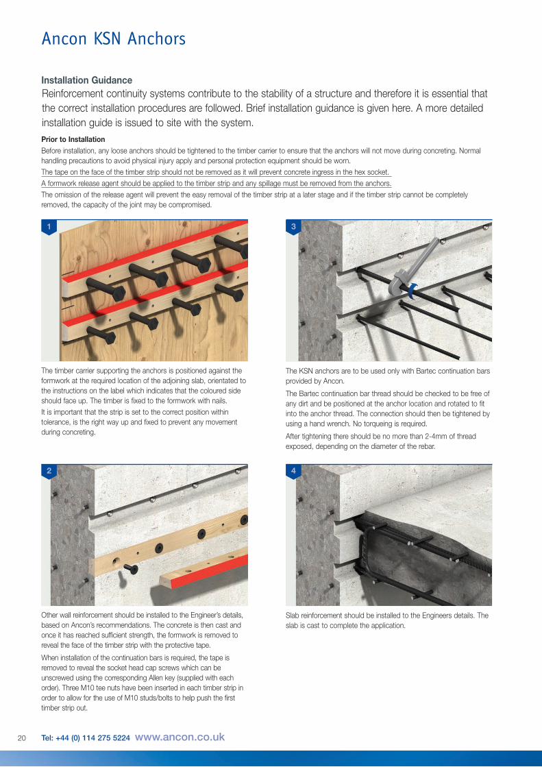
Installation GuidanceReinforcement continuity systems contribute to the stability of a structure and therefore it is essential thatthe correct installation procedures are followed. Brief installation guidance is given here. A more detailedinstallation guide is issued to site with the system.
1
Prior to InstallationBefore installation, any loose anchors should be tightened to the timber carrier to ensure that the anchors will not move during concreting. Normalhandling precautions to avoid physical injury apply and personal protection equipment should be worn.The tape on the face of the timber strip should not be removed as it will prevent concrete ingress in the hex socket. A formwork release agent should be applied to the timber strip and any spillage must be removed from the anchors.The omission of the release agent will prevent the easy removal of the timber strip at a later stage and if the timber strip cannot be completelyremoved, the capacity of the joint may be compromised.
The timber carrier supporting the anchors is positioned against theformwork at the required location of the adjoining slab, orientated tothe instructions on the label which indicates that the coloured sideshould face up. The timber is fixed to the formwork with nails.It is important that the strip is set to the correct position withintolerance, is the right way up and fixed to prevent any movementduring concreting.
The KSN anchors are to be used only with Bartec continuation barsprovided by Ancon.
The Bartec continuation bar thread should be checked to be free ofany dirt and be positioned at the anchor location and rotated to fitinto the anchor thread. The connection should then be tightened byusing a hand wrench. No torqueing is required.
After tightening there should be no more than 2-4mm of threadexposed, depending on the diameter of the rebar.
Other wall reinforcement should be installed to the Engineer’s details,based on Ancon’s recommendations. The concrete is then cast andonce it has reached sufficient strength, the formwork is removed toreveal the face of the timber strip with the protective tape.
When installation of the continuation bars is required, the tape isremoved to reveal the socket head cap screws which can beunscrewed using the corresponding Allen key (supplied with eachorder). Three M10 tee nuts have been inserted in each timber strip inorder to allow for the use of M10 studs/bolts to help push the firsttimber strip out.
Slab reinforcement should be installed to the Engineers details. Theslab is cast to complete the application.
3
2 4

21
Installation TolerancesIn order to ensure adequate cover to the continuation bar and tocomply with the design, it is important that the timber anchor carrieris set to the correct position, the right way up and fixed to preventany movement during concreting. The carrier's installation tolerancesare shown below and these tolerances are not cumulative.
Tools required for installation: KSN 12 - 10mm A/F Allen Key / Hex Head WrenchKSN 16 - 12mm A/F Allen Key / Hex Head Wrench KSN 20 - 14mm A/F Allen Key / Hex Head WrenchM10 Stud/bolt to push timber away from concreteHand Wrench to suit continuation bar diameter
Other requirement: Formwork release agent
Length of Continuation Deviation Bar (mm) d
700 +/- 2mm1000 +/- 3mm1500 +/- 5mm
Length of Continuation Deviation Bar (mm) d
700 +/- 10mm1000 +/- 12mm1500 +/- 20mm
+/- 10mm
Target Position
Length of Continuation bar
Slab
Wall
Wall
Deviation d
Length of Continuation bar
Deviation d
Actual Position
+/- 5mm
Timber Anchor Carrier Setting Out Deviation Allowances
Vertical Transverse Section Alignment of Anchor Side View
Horizontal Transverse Section Alignment of Anchor Plan View

22 Tel: +44 (0) 114 275 5224 www.ancon.co.uk
Ancon KSN Anchors
Guidance for cutting standard length anchor carrierIn some instances, at the end of a run of anchors for example, a non-standard carrier length may berequired. In order to achieve this, the standard timber carrier may be cut to suit, under the followingconditions:
• Anchor carriers are to be installed end toend without any gaps between them at alllocations
• The specified spacing between anchorsmust never be exceeded
• The actual anchor spacing can be reducedto below the specified spacing but with aminimum of 150mm
• Minimum edge distance should be 100mm
Length to end of the wall is less than standard carrier length
Length is less than standardcarrier length
Standard carrier with ends cut tosuit gap between standard carriers
Standard carrier with ends cut tosuit gap between standard carriers
Standard carrier with endscut to suit edge of the wall
Standard length carrier
Standard length carrier Standard length carrier
Standard carrier with ends cut tosuit edge of the wall
Cut in the middle of a run
Cut at the end of a run
Standard length carrier
Specified spacingSx
Sx
0.5Sx
0.5Sx
≤0.5Sx
≤0.5Sx≤Sx
≥100
Standard length carrier Standard length carrier
Specified spacing
Specified spacing
SxSx
Sx
0.5Sx0.5Sx≤0.5Sx
≤0.5Sx
≤0.5Sx
Wall Elevation
Wall Elevation
Plan View
Plan View
Reinforcing Bar Couplers
The use of reinforcing bar couplers can providesignificant advantages over lapped joints.Design and construction of the concrete canbe simplified and the amount of reinforcementrequired can be reduced. The Ancon rangeincludes Bartec parallel threaded, TT taperedthreaded and MBT mechanically boltedcouplers.
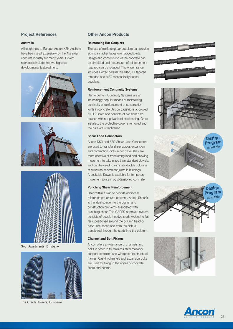
Australia
Although new to Europe, Ancon KSN Anchorshave been used extensively by the Australianconcrete industry for many years. Projectreferences include the two high risedevelopments featured here.
Shear Load Connectors
Ancon DSD and ESD Shear Load Connectorsare used to transfer shear across expansionand contraction joints in concrete. They aremore effective at transferring load and allowingmovement to take place than standard dowels,and can be used to eliminate double columnsat structural movement joints in buildings.A Lockable Dowel is available for temporarymovement joints in post-tensioned concrete.
Punching Shear Reinforcement
Used within a slab to provide additionalreinforcement around columns, Ancon Shearfixis the ideal solution to the design andconstruction problems associated withpunching shear. This CARES-approved systemconsists of double-headed studs welded to flatrails, positioned around the column head orbase. The shear load from the slab istransferred through the studs into the column.
Channel and Bolt Fixings
Ancon offers a wide range of channels andbolts in order to fix stainless steel masonrysupport, restraints and windposts to structuralframes. Cast-in channels and expansion boltsare used for fixing to the edges of concretefloors and beams.
Reinforcement Continuity Systems
Reinforcement Continuity Systems are anincreasingly popular means of maintainingcontinuity of reinforcement at constructionjoints in concrete. Ancon Eazistrip is approvedby UK Cares and consists of pre-bent barshoused within a galvanised steel casing. Onceinstalled, the protective cover is removed andthe bars are straightened.
23
Other Ancon ProductsProject References
Soul Apartments, Brisbane
The Oracle Towers, Brisbane

ISO 9001: 2008FM 12226
ISO 14001: 2004EMS 505377
OHSAS 18001: 2007OHS 548992
© Ancon Building Products 2013
The construction applications and details provided in this literature are indicative only. In every case, project workingdetails should be entrusted to appropriately qualified and experienced persons.
Whilst every care has been exercised in the preparation of this document to ensure that any advice, recommendations orinformation is accurate, no liability or responsibility of any kind is accepted in respect of Ancon Building Products.
With a policy of continuous product development Ancon Building Products reserves the right to modify product designand specification without due notice.
These products are available from:
Masonry Support Systems
Lintels
Masonry Reinforcement
Windposts and Parapet Posts
Wall Ties and Restraint Fixings
Channel and Bolt Fixings
Tension and Compression Systems
Insulated Balcony Connectors
Shear Load Connectors
Punching Shear Reinforcement
Reinforcing Bar Couplers
Reinforcement Continuity Systems
Stainless Steel Fabrications
Flooring and Formed Sections
Refractory Fixings
Ancon Building Products114 Kurrajong AvenueMount DruittSydneyNSW 2770AustraliaTel: +61 (0) 2 8808 1111Fax: +61 (0) 2 9675 3390Email: [email protected]: www.ancon.com.au
Ancon (Schweiz) AGGewerbezone Widalmi 103216 Ried bei KerzersSwitzerlandTel: +41 (0) 31 750 3030Fax: +41 (0) 31 750 3033 Email: [email protected]: www.ancon.ch
Ancon Building Products GesmbHPuchgasse 1A-1220 ViennaAustriaTel: +43 (0) 1 259 58 62-0Fax: +43 (0) 1 259 58 62-40Email: [email protected]: www.ancon.at
Ancon GmbHBartholomäusstrasse 2690489 NurembergGermanyTel: +49 (0) 911 955 1234 0Fax: +49 (0) 911 955 1234 9Email: [email protected]: www.anconbp.de
Ancon Building ProductsPresident Way, President ParkSheffield S4 7URUnited KingdomTel: +44 (0) 114 275 5224Fax: +44 (0) 114 276 8543Email: [email protected]: www.ancon.co.ukFollow on Twitter: @AnconUK
Ancon (Middle East) FZEPO Box 17225Jebel AliDubaiUnited Arab EmiratesTel: +971 (0) 4 883 4346Fax: +971 (0) 4 883 4347Email: [email protected]: www.ancon.ae