Kraft Pulping and Recovery Process basics - UT …biorefinery.utk.edu/technical_reviews/Kraft...
50
Basics of Kraft Pulping & Recovery Process Art J. Ragauskas Art J. Ragauskas Institute of Paper Science and Technology Institute of Paper Science and Technology Georgia Institute of Technology Georgia Institute of Technology
Transcript of Kraft Pulping and Recovery Process basics - UT …biorefinery.utk.edu/technical_reviews/Kraft...
Basics of Kraft Pulping & Recovery Process
Art J. Ragauskas Art J. Ragauskas Institute of Paper Science and TechnologyInstitute of Paper Science and Technology
Georgia Institute of TechnologyGeorgia Institute of Technology

Outline
• History• Goals• Process Overview• Kraft Pulping Process• Kraft Recovery
– Power Plant– Caustic Plant
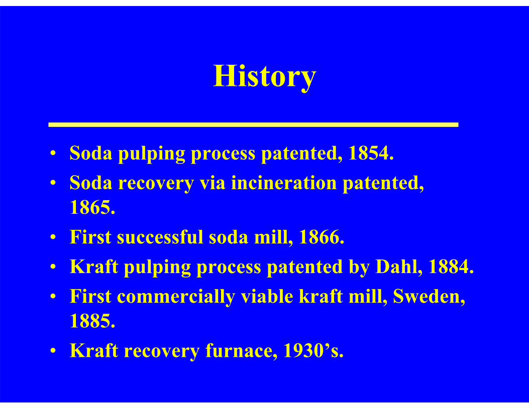
History
• Soda pulping process patented, 1854.• Soda recovery via incineration patented,
1865.• First successful soda mill, 1866.• Kraft pulping process patented by Dahl, 1884.• First commercially viable kraft mill, Sweden,
1885.• Kraft recovery furnace, 1930’s.
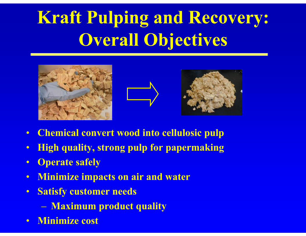
Kraft Pulping and Recovery:Overall Objectives
• Chemical convert wood into cellulosic pulp• High quality, strong pulp for papermaking• Operate safely• Minimize impacts on air and water• Satisfy customer needs
– Maximum product quality• Minimize cost
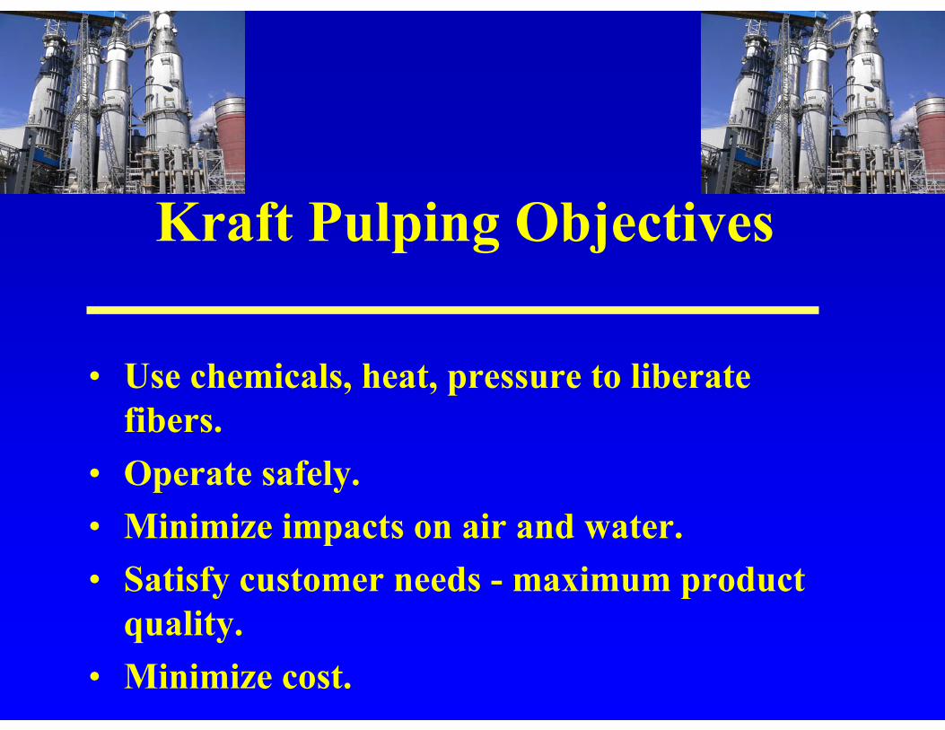
Kraft Pulping Objectives
• Use chemicals, heat, pressure to liberate fibers.
• Operate safely.• Minimize impacts on air and water.• Satisfy customer needs - maximum product
quality.• Minimize cost.
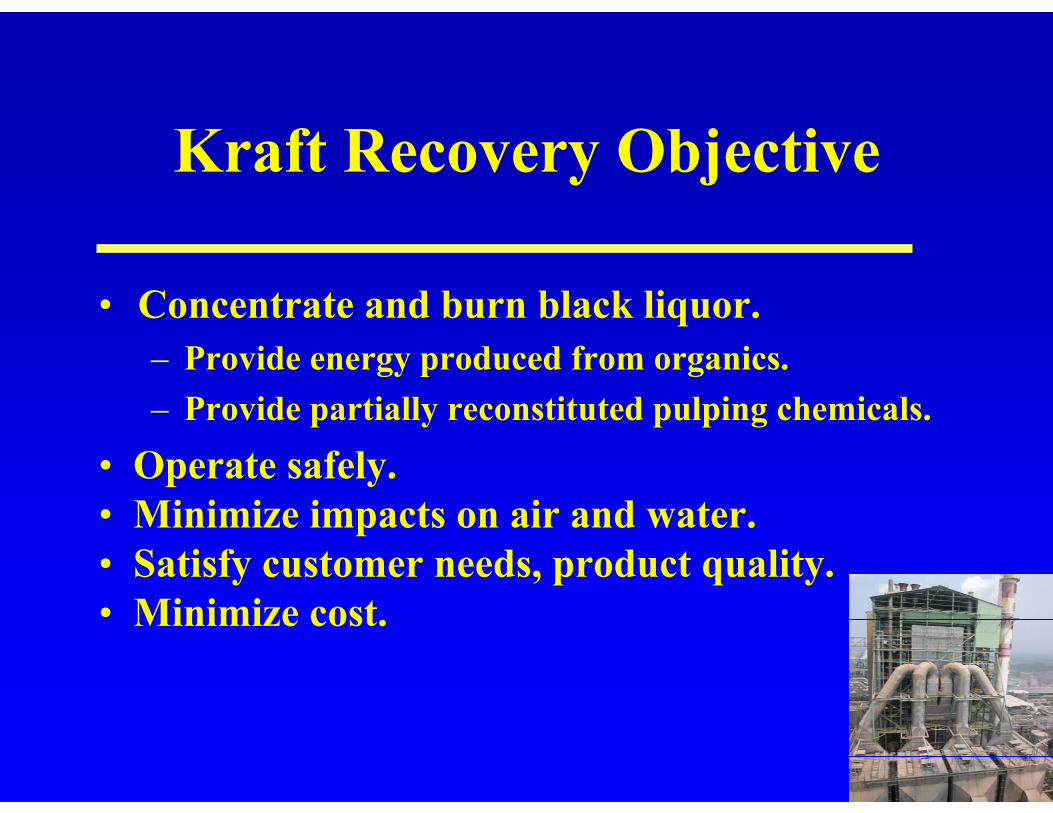
Kraft Recovery Objective
• Concentrate and burn black liquor.– Provide energy produced from organics.– Provide partially reconstituted pulping chemicals.
• Operate safely.• Minimize impacts on air and water.• Satisfy customer needs, product quality.• Minimize cost.
Kraft Caustic Plant Objective
• Final step in reconstituting pulping chemicals.– Provides fresh cooking liquor.– Regenerates lime from lime mud.
• Operate safely.• Minimize impacts on air and water.• Satisfy customer needs, product quality.• Minimize cost.
The Kraft Pulping and Recovery Process
Dale Proctor, 2003
• Process overview.
Dale Proctor, 2003
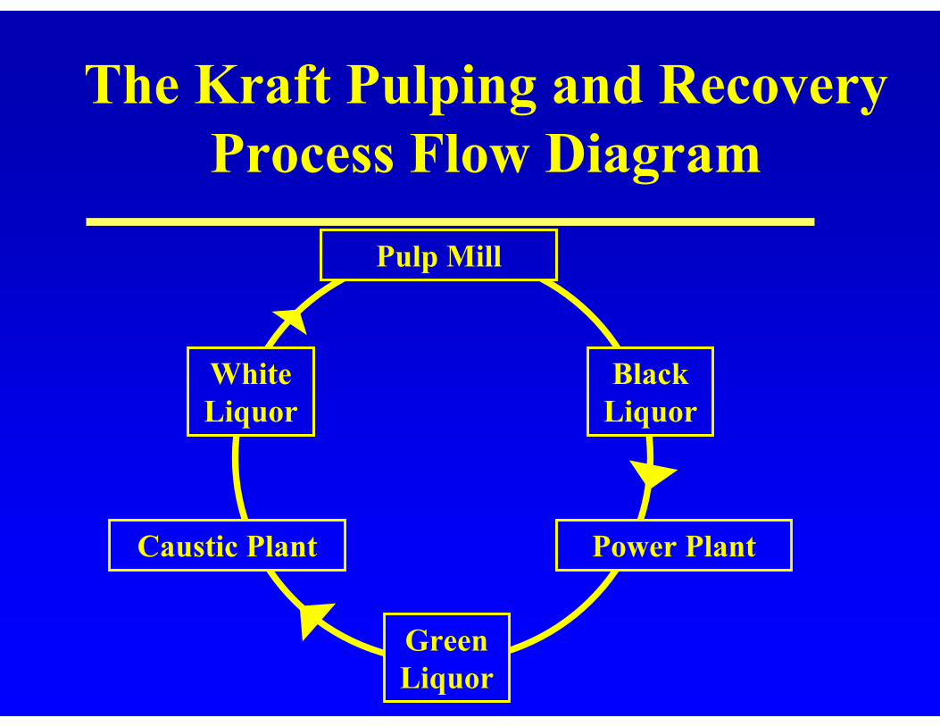
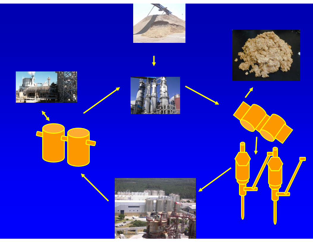
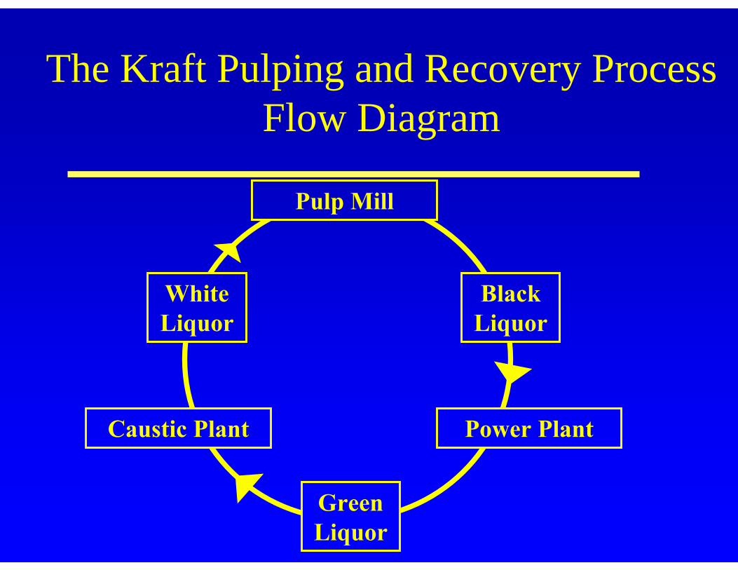
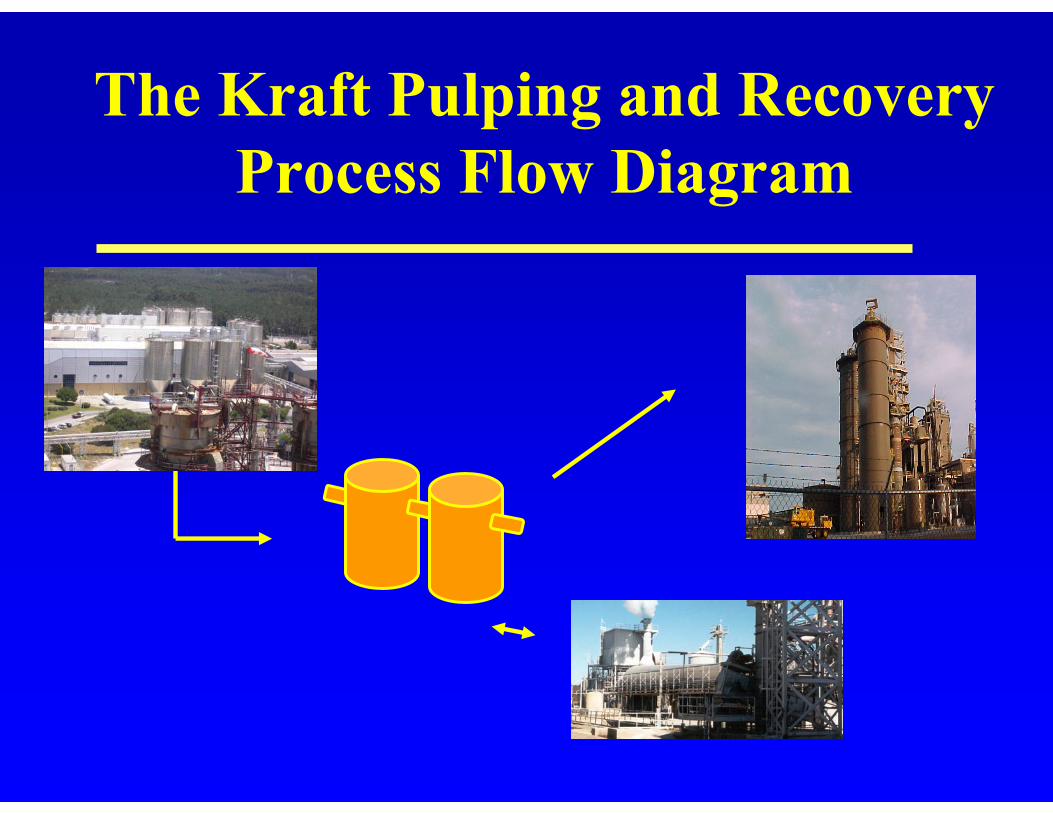
The Kraft Pulping and Recovery Process Flow Diagram
Power PlantCaustic Plant
Pulp Mill
Black Liquor
Green Liquor
White Liquor

The Kraft Pulping and Recovery Basic Process Flow
Pulp Mill
Dale Proctor, 2003
White Liquor
•NaOH
•Na2S
Pulp Mill
•Cooking
•Washing
Black Liquor
Turpentine
pulp
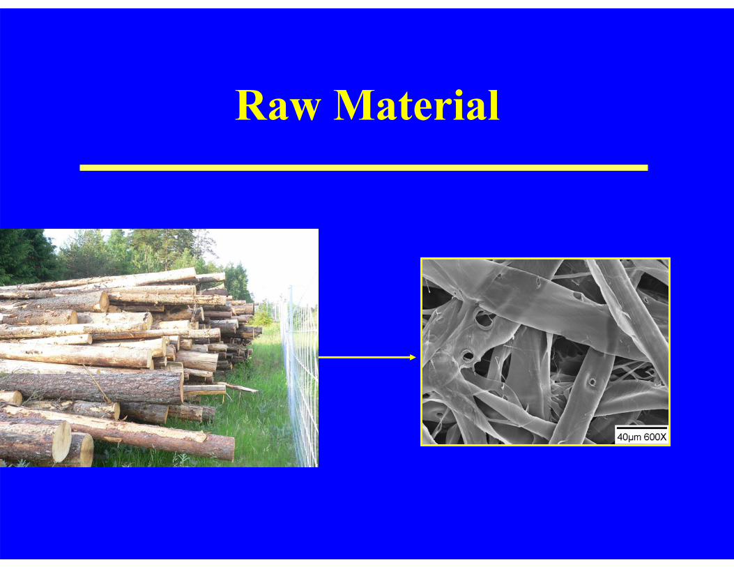
Raw Material
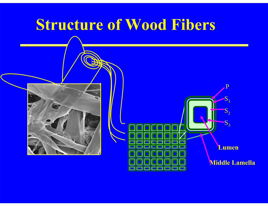
Structure of Wood Fibers
Lumen
P
S1
S2
S3
Middle Lamella

Chemical Structure of Fibers
OO
HOOH
OO
HOOH
O
HOOH
OO
HOOH
O-XylanO
n: 100 - 200
Substituted with OH3CO
HOOH
O
HO2CO
CH3
25 – 35 %
Extractives 2 – 8 %OO
CH2OH
OCH3
O
OH
H3CO
CHOH
CH2
CH2OH
H3CO
OH
OH
O
H3CO
HO
OH
O
H3CO
OH
OH
O
H3CO
20-30 %
OH
HO
HHOH H
OH
H
HO
OH
HHOH HOH
HO
HO
OH
O
HHOH HOH
HO
HO
OH
HHOH HOH
HOH
HO
n40 – 47 %
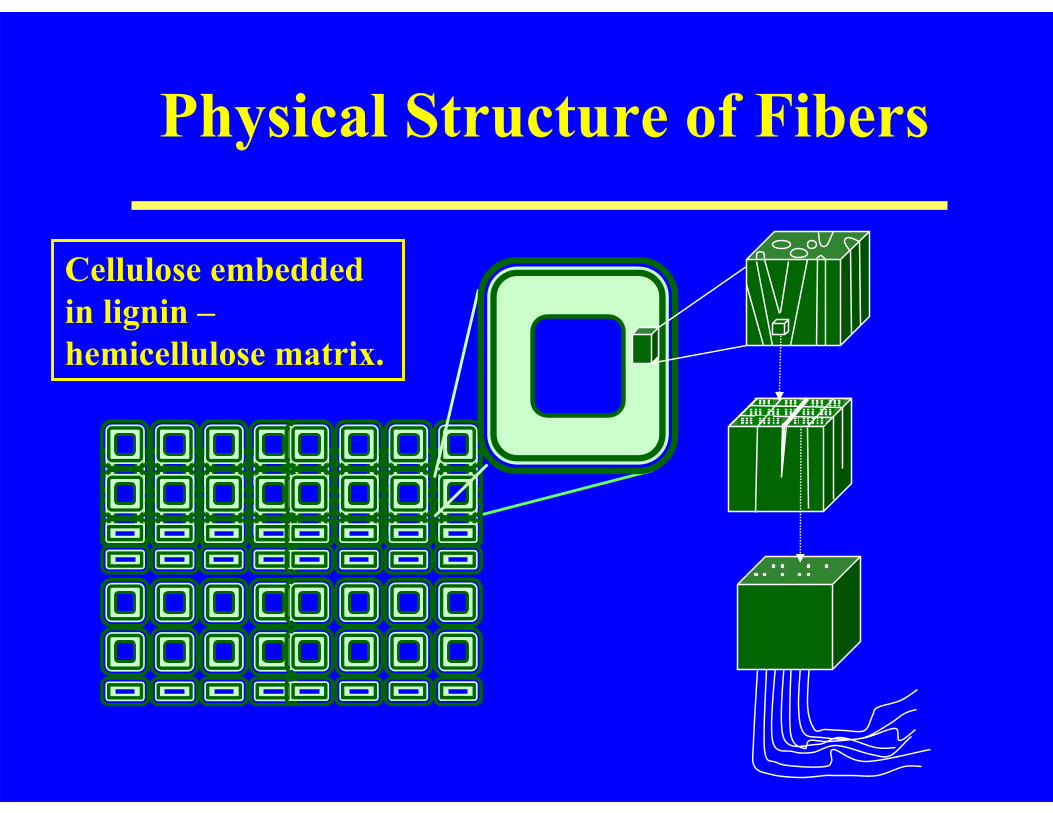
Physical Structure of Fibers
Cellulose embedded in lignin –hemicellulose matrix.
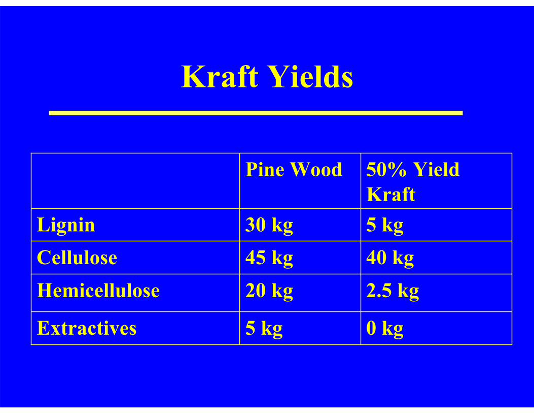
Kraft Yields
0 kg5 kgExtractives
2.5 kg20 kgHemicellulose40 kg45 kgCellulose5 kg30 kgLignin
50% Yield Kraft
Pine Wood
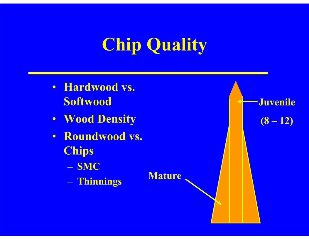
Chip Quality
• Hardwood vs. Softwood
• Wood Density• Roundwood vs.
Chips– SMC– Thinnings
Juvenile
(8 – 12)
Mature
Chip Storage
• Manage Chip Pile– By-Products– Acid Hydrolysis– Yield
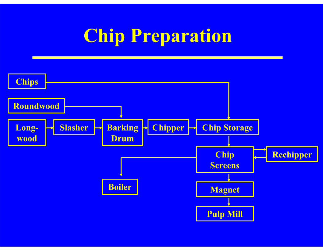
Chip Preparation
Chips
Roundwood
Chip Screens
Magnet
Pulp Mill
Rechipper
Slasher Barking Drum
Chip Storage ChipperLong-wood
Boiler

Kraft Pulping
Dale Proctor, 2003
• White Liquor– NaOH + NaSH– Dissolve & Fragment
Lignin– Peeling and Chain
Scission of Polysaccharides
Power PlantCaustic Plant
Pulp Mill
Black Liquor
Green Liquor
White Liquor
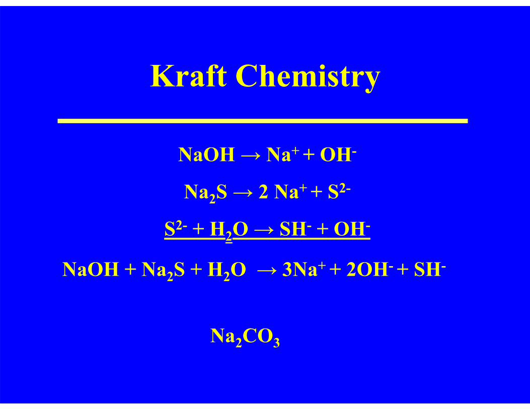
Kraft Chemistry
NaOH + Na2S + H2O → 3Na+ + 2OH- + SH-
NaOH → Na+ + OH-
Na2S → 2 Na+ + S2-
S2- + H2O → SH- + OH-
Na2CO3
Dale Proctor, 2003
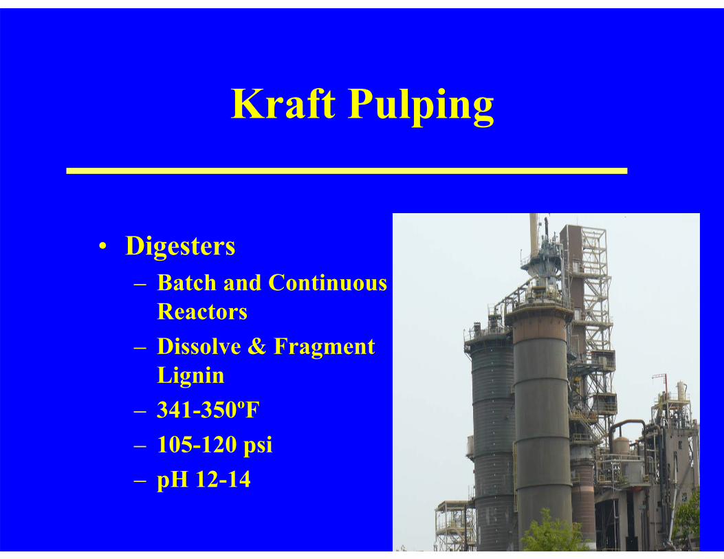
Kraft Pulping
Dale Proctor, 2003
• Digesters– Batch and Continuous
Reactors– Dissolve & Fragment
Lignin– 341-350ºF– 105-120 psi– pH 12-14
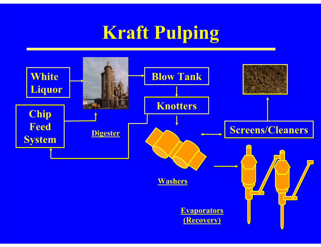
Kraft Pulping
Blow Tank
Washers
Evaporators (Recovery)
Knotters
Screens/CleanersDigester
White Liquor
Chip Feed
System
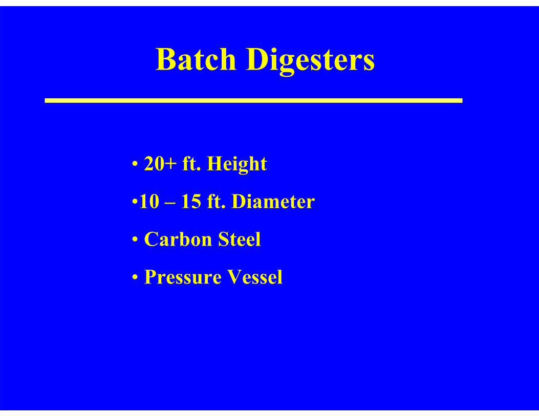
Batch Digesters
• 20+ ft. Height
•10 – 15 ft. Diameter
• Carbon Steel
• Pressure Vessel
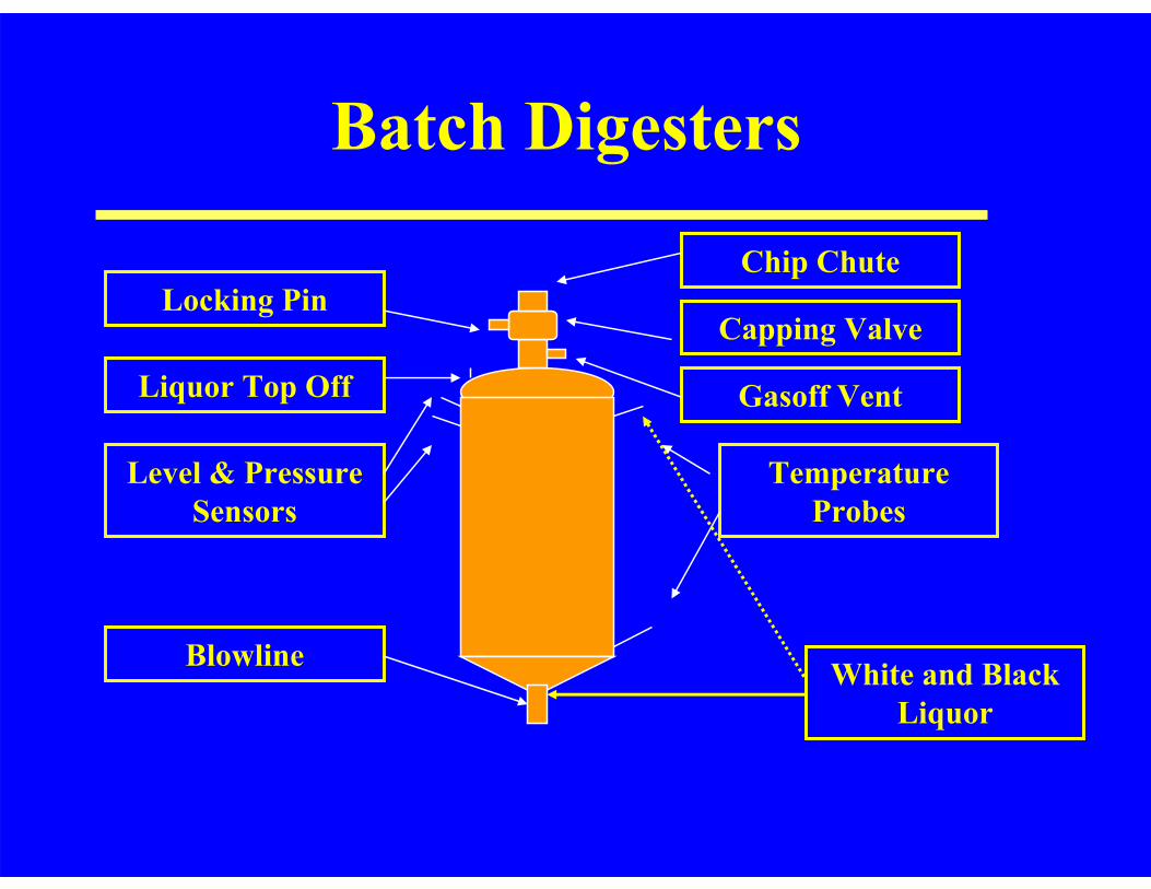
Batch Digesters
Chip ChuteLocking Pin
Liquor Top Off
Level & Pressure Sensors
Blowline
Temperature Probes
Capping Valve
Gasoff Vent
White and Black Liquor

Continuous Digesters: Chip Feed System
• Pressurized Feed System

Low Pressure Feeder
High Pressure Feeder
Top Separator
Chip Bin
Steaming Vessel
Inline Drainers
Impregnation Zone
Chip ChuteWhite Liquor

Continuous Digesting System
• Carbon Steel
• Pressure Vessel
• 200 – 250 ft Height.
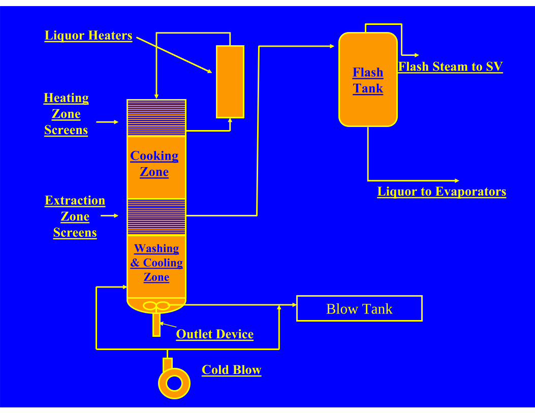
Outlet Device
Blow Tank
Cold Blow
Heating Zone
Screens
Cooking Zone
ExtractionZone
ScreensWashing
& Cooling Zone
FlashTank
Liquor to Evaporators
Flash Steam to SV
Liquor Heaters
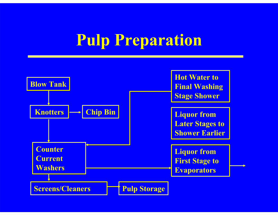
Pulp Preparation
Blow Tank
Knotters
Counter CurrentWashers
Screens/Cleaners
Chip Bin
Pulp Storage
Liquor from First Stage to Evaporators
Liquor from Later Stages to Shower Earlier
Hot Water to Final Washing Stage Shower
Kraft Chemistry
• Extractives– Dissolved– Turpentine– Tall Oil
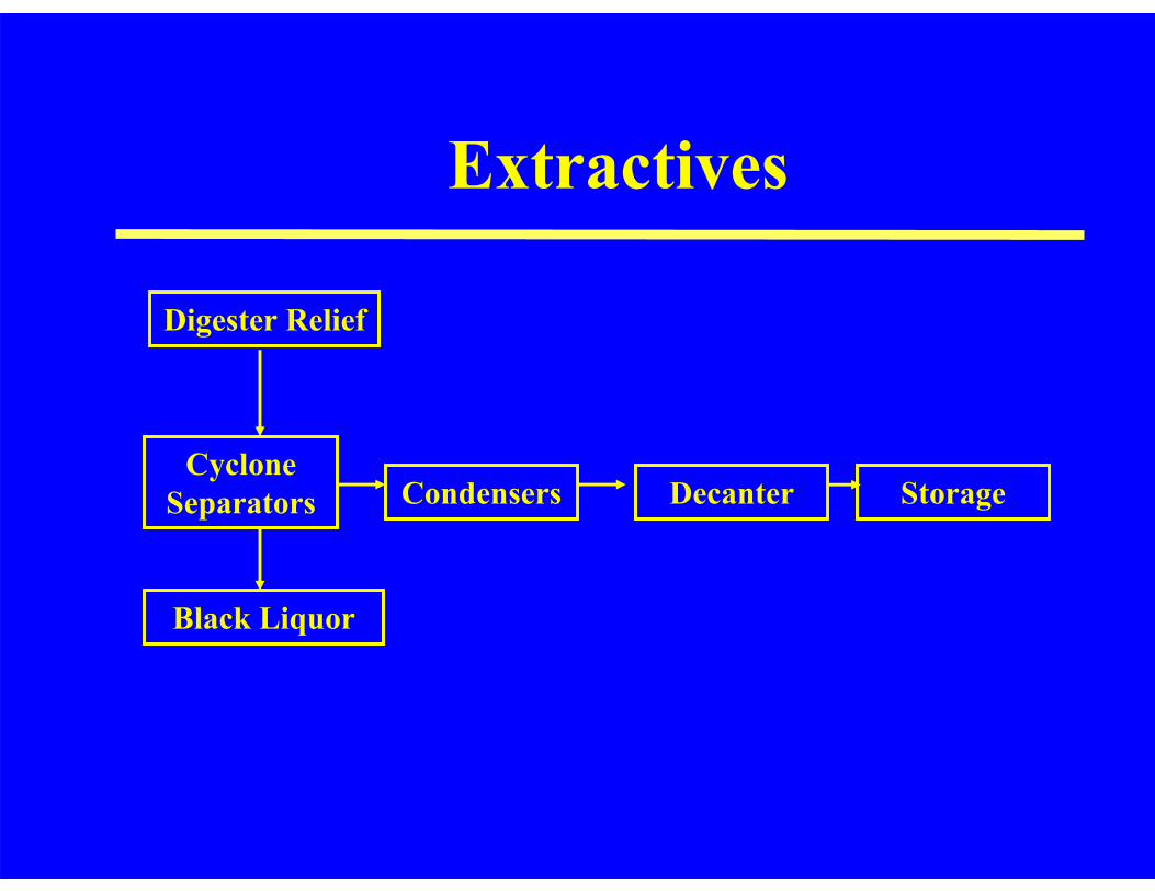
Extractives
Digester Relief
Black Liquor
CondensersCyclone
Separators StorageDecanter
The Kraft Pulping and Recovery Process Flow Diagram
Power PlantCaustic Plant
Pulp Mill
Black Liquor
Green Liquor
White Liquor
Power Plant
• Kraft Recovery– Black Liquor Evaporation– Recovery Boiler
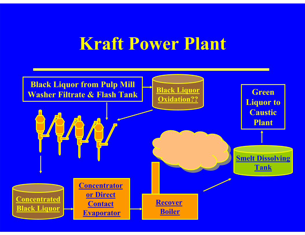
Black Liquor from Pulp Mill Washer Filtrate & Flash Tank
Recover Boiler
Green Liquor to Caustic Plant
ConcentratedBlack Liquor
Smelt DissolvingTank
Kraft Power Plant
Black LiquorOxidation??
Concentrator or Direct Contact
Evaporator
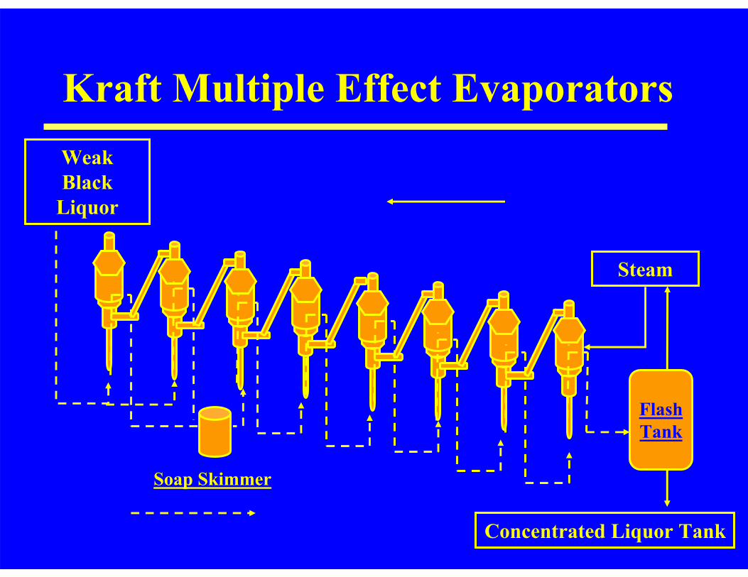
Kraft Multiple Effect EvaporatorsWeak Black
Liquor
Steam
FlashTank
Concentrated Liquor Tank
Soap Skimmer
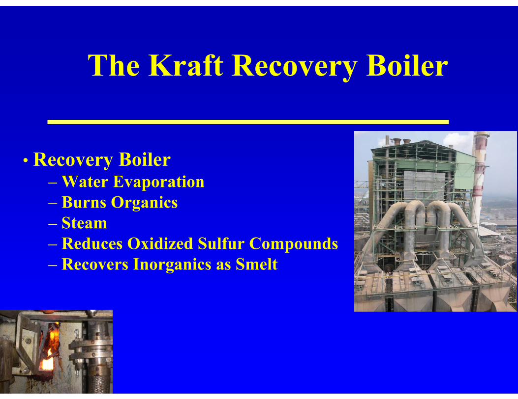
The Kraft Recovery Boiler
• Recovery Boiler– Water Evaporation– Burns Organics– Steam– Reduces Oxidized Sulfur Compounds – Recovers Inorganics as Smelt
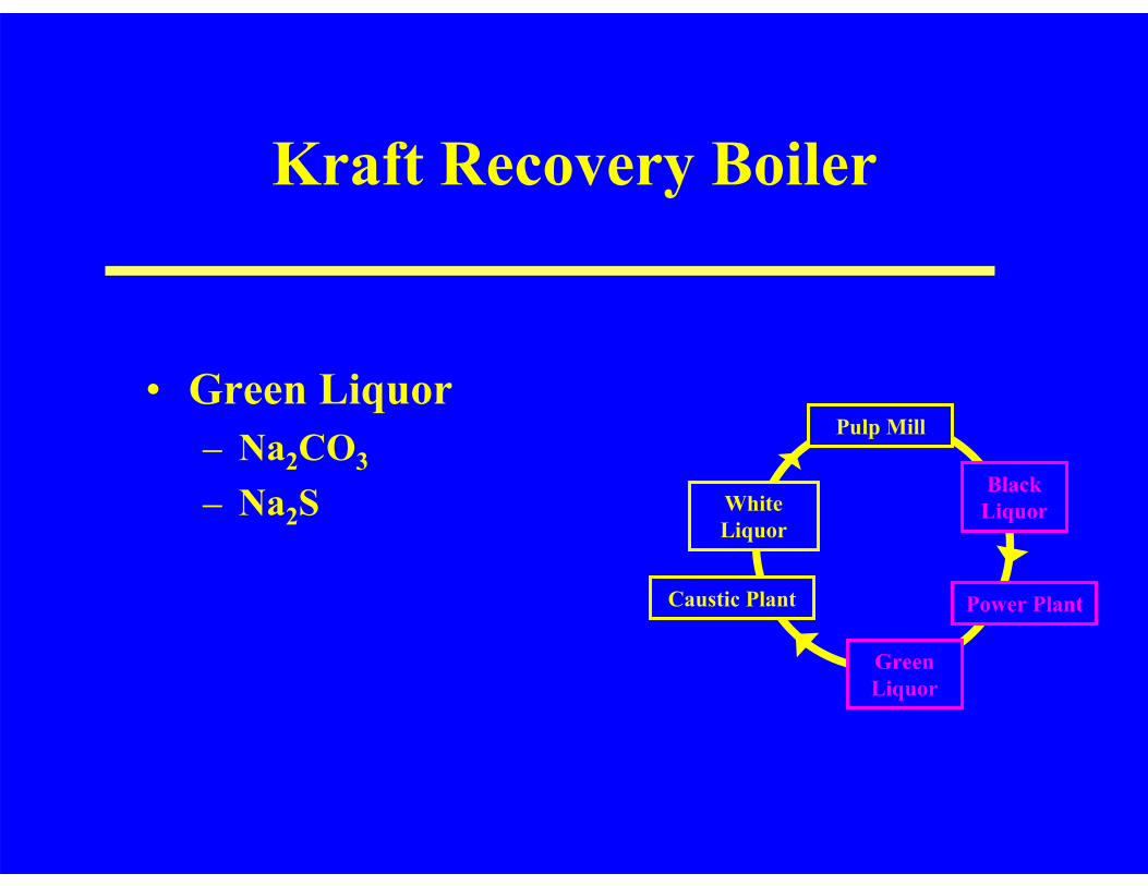
Kraft Recovery Boiler
Dale Proctor, 2003
• Green Liquor– Na2CO3
– Na2S
Power PlantCaustic Plant
Pulp Mill
Black Liquor
Green Liquor
White Liquor
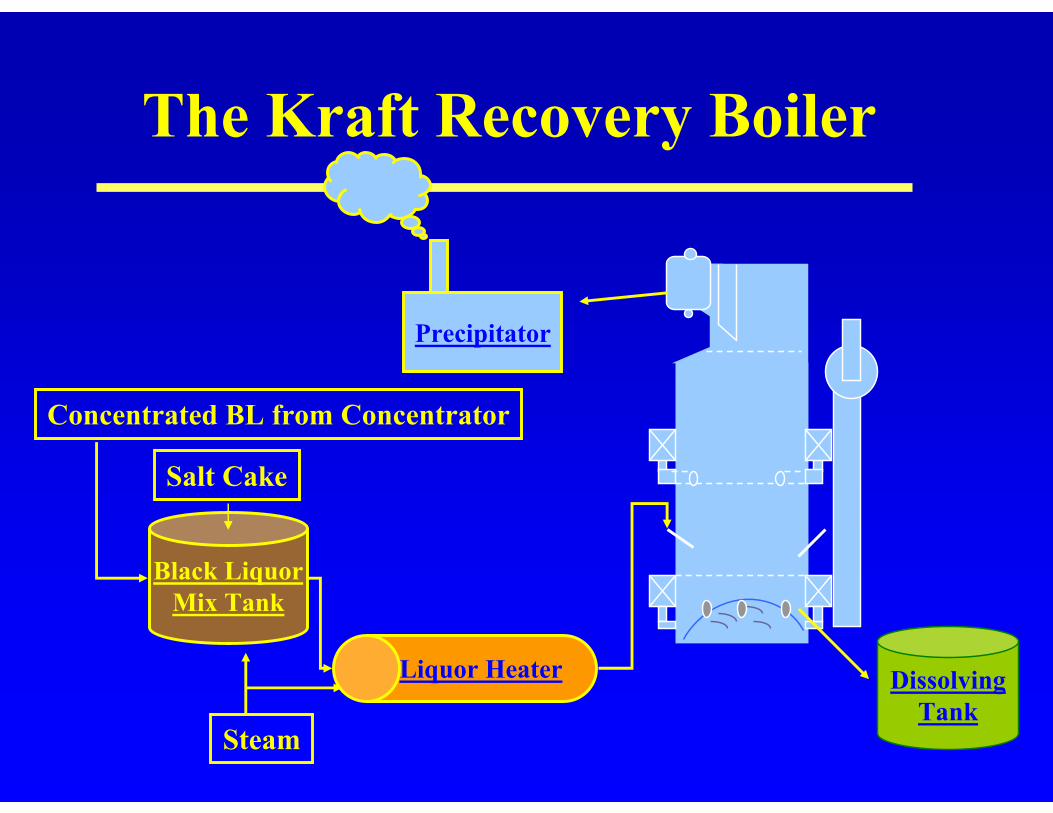
The Kraft Recovery Boiler
Black LiquorMix Tank
Concentrated BL from Concentrator
Salt Cake
Liquor Heater
Precipitator
DissolvingTank
Steam
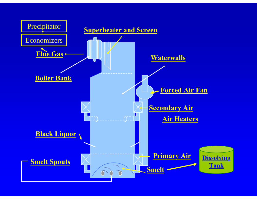
Forced Air Fan
Air Heaters
Smelt Spouts
Waterwalls
Boiler Bank
Flue Gas
Smelt
Primary Air
Secondary Air
Black Liquor
Superheater and ScreenEconomizers
DissolvingTank
Precipitator
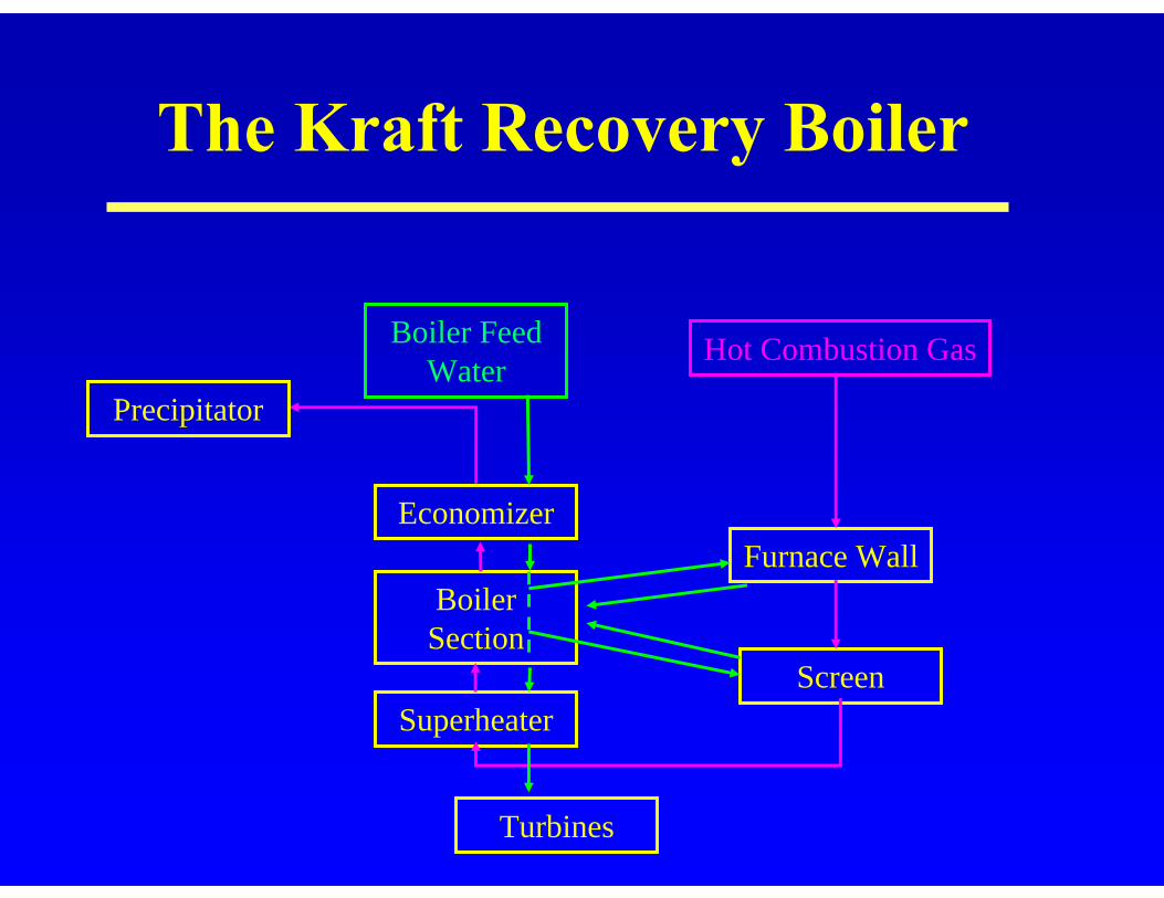
Economizer
Boiler Section
Superheater
Furnace Wall
Screen
Hot Combustion GasBoiler Feed Water
Precipitator
Turbines
The Kraft Recovery Boiler

Oxidizing
Drying
Reduction
The Kraft Recovery Boiler
Oxidation
Na2S + 3/2 O2 + CO2 → Na2CO3 + SO2
Pyrolysis
Na2S + H2O + CO2 → Na2CO3 + H2S
Reduction
Na2SO4 + 2C → Na2S + 2CO2
Na2SO4 + 4C → Na2S + 4CO

The Kraft Pulping and Recovery Process Flow Diagram
Power PlantCaustic Plant
Pulp Mill
Black Liquor
Green Liquor
White Liquor
The Kraft Pulping and Recovery Process Flow Diagram
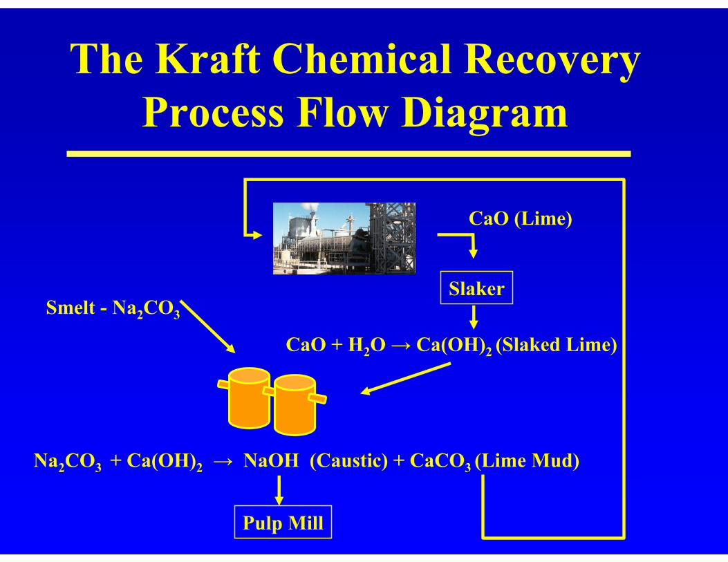
Smelt - Na2CO3
Na2CO3 + Ca(OH)2 → NaOH (Caustic) + CaCO3 (Lime Mud)
CaO + H2O → Ca(OH)2 (Slaked Lime)
CaO (Lime)
Slaker
The Kraft Chemical Recovery Process Flow Diagram
Pulp Mill
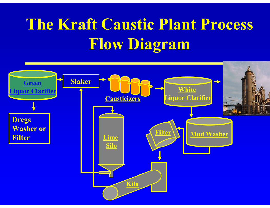
The Kraft Caustic Plant Process Flow Diagram
Dregs Washer or Filter
Slaker
Causticizers
GreenLiquor Clarifier White
Liquor Clarifier
Mud WasherFilterLime Silo
Kiln
Safety
• Pulp Mill - Acid Cleaning– Digester, Liquor Heaters, Inline Drainers
• Power Plant - Smelt Water Explosions• Caustic Plant - Gas in Kiln
Environmental Concerns
• Water– Acid Cleaning– Liquor Spills
• Air– Stacks

Thank You!