KP,ACB,UT,RT Presostati i Termostati
27
36 Područja primene Prednosti Osobine KP: Odlično funkcionisanje i laka montaža Presostati serije KP su konstruisani da zaštite rashladne instalacije od previsokih pritisaka na potisu, pren- iskih pritisaka na usisu, da pokreću/zaustavljaju kompresore ili da upravljaju ventilatorima na vazduhom hlađenim kondenzatorima. KP termostati sa adsorpcionim punjenjem su optimalan izbor za zaštitu od smrzavanja čilera. Pojačani sistem kontakata za 16 A omogućava da rade sa elektromotorima do 2 kW direktno, bez upotrebe kontaktora. Karakteristike · Rashladna tehnika · Toplotne pumpe · Klima uređaji · Čileri · Hlađenje u transportu · Laki za rukovanje, kompaktne kon- strukcije sa velikim i vidljivim skalama. · Naročito otporni na vibracije i udare. · Tačan i pouzdan rad kompresora usled odlične elektromehaničke funkcije. · Jednostavna provera funkcionalnosti ručnim testiranjem funkcije kontakata (bez upotrebe alata). · Jednostavno se montira električni priključak, što takođe olakšava montažu. · Može se upotrebljavati za sve vrste freona. · Odobrenja: CE i UL. · Presostati raspoloživi sa navojnim, lemnim ili priključcima sa kapilarnom cevi. · Termostati su dostupni sa kapilarnim senzorom, senzorom za vazduh ili sen- zorom za smeštanje u čauru/cilindrični džep. · Stepen zaštite IP30 i IP44. · KP 6, 7 i 17 sa sigurnosnim mehom. Ručno testiranje Široka područja pritisaka Kompatibilni sa R410A i CO 2 Potpuno zavareni meh / sigurnosni meh Navojni ili hermetički nepropusni lemni priključci Pouzdana i potpuno vidljiva funkcija uključivanja/isključivanja Veliko opterećenje kontakata; 16 A, 400V Otporni na vibracije Kompaktna konstrukcija
description
Catalogue
Transcript of KP,ACB,UT,RT Presostati i Termostati
36
Područja primene Prednosti Osobine
KP: Odlično funkcionisanje i laka montaža
Presostati serije KP su konstruisani da zaštite rashladne instalacije od previsokih pritisaka na potisu, pren-
iskih pritisaka na usisu, da pokreću/zaustavljaju kompresore ili da upravljaju ventilatorima na vazduhom
hlađenim kondenzatorima. KP termostati sa adsorpcionim punjenjem su optimalan izbor za zaštitu od
smrzavanja čilera. Pojačani sistem kontakata za 16 A omogućava da rade sa elektromotorima do 2 kW
direktno, bez upotrebe kontaktora.
Karakteristike
· Rashladna tehnika
· Toplotne pumpe
· Klima uređaji
· Čileri
· Hlađenje u transportu
· Laki za rukovanje, kompaktne kon-
strukcije sa velikim i vidljivim skalama.
· Naročito otporni na vibracije i udare.
· Tačan i pouzdan rad kompresora usled
odlične elektromehaničke funkcije.
· Jednostavna provera funkcionalnosti
ručnim testiranjem funkcije kontakata
(bez upotrebe alata).
· Jednostavno se montira električni
priključak, što takođe olakšava
montažu.
· Može se upotrebljavati za sve vrste
freona.
· Odobrenja: CE i UL.
· Presostati raspoloživi sa navojnim,
lemnim ili priključcima sa kapilarnom
cevi.
· Termostati su dostupni sa kapilarnim
senzorom, senzorom za vazduh ili sen-
zorom za smeštanje u čauru/cilindrični
džep.
· Stepen zaštite IP30 i IP44.
· KP 6, 7 i 17 sa sigurnosnim mehom.
Ručno testiranje
Široka područja pritisaka
Kompatibilni sa
R410A i CO2
Potpuno zavareni
meh / sigurnosni meh Navojni ili hermetički nepropusni
lemni priključci
Pouzdana i potpuno vidljiva funkcija
uključivanja/isključivanja
Veliko opterećenje
kontakata; 16 A, 400V
Otporni na vibracije
Kompaktna konstrukcija

37
A
B
C
E
F
Presostati i termostati – KP
Tehnički podaci i poručivanje
Presostati za freone
Tip Pritisak
Nizak pritisak (LP) Visok pritisak (HP) Reset
Sistemkontakata
Porudžbeni broj 1)
Opsegregulacije
bar
Diferencapbar
Opsegregulacije
bar
Diferencapbar
LP HP ¼ in.
6 mmnavojni
¼ in.ODF
lemni
6 mmODF
lemni
KP 5 Visoki 8 321.8 6.0 Aut.
SPDT060-117166 060-117966 060-117766
Fiksna 3 Ručni 060-117366 060-118066 060-117866
KP 15Kombi-
novani0.2 7.5 0.7 4.0 8 32 Fiksna 4
Aut.
Aut.SPDT + LP
signal
060-124166 060-125466
Ručni060-124366
060-126166
Aut.SPDT + LP/HP
signal
060-126566 060-129966
Ručni 060-126466 060-128466
Podesiv Podesiv 060-115466 060-001066
Presostati sa DIN 32733 odobrenjem za freone
Tip 2) Pritisak
Nizak pritisak (LP) Visok pritisak (HP) Reset
Sistemkontakata
Porudžbeni broj 1)
Opsegregulacije
bar
Diferenca
Δp
bar
Opsegregulacije
bar
Diferenca
Δp
bar
LP HP¼ in.
6 mmnavojni
¼ in.
ODFlemni
6 mm
ODF
lemni
KP 1 Niski0.2 7.5 0.7 4.0 Aut.
SPDT060-110166 060-111266 060-111066
0.9 7.0 Fiksna 0.7 Ručni 060-110366 060-111166 060-110966
KP 2 Niski 0.2 5.0 0.4 1.5 Aut. SPDT 060-112066 060-112366
KP 6W Visoki 8 42 4 10 Aut. SPDT 060-519066
KP 6B Visoki 8 42 Fiksna 4 Ručni SPDT 060-519166
KP 7W Visoki 8 32 4 10 Aut. SPDT 060-119066 060-120366
KP 7B Visoki 8 32 Fiksna 4 Ručni SPDT 060-119166
KP 7BSKombi-
novani8 32 Fiksna 4
Man./
RučniSPST 060-120066
KP 17WKombi-
novani0.2 7.5 0.7 4 8 32 Fiksna 4 Aut. Aut.
SPDT + LP/HP
signal060-127566 060-127666
KP 17BKombi-
novani0.2 7.5 0.7 4 8 32 Fiksna 4 Aut. Ručni SPDT 060-126866 060-127466
KP17WBKombi-
novani0.2 7.5 Fiksna 1 8 32 Fiksna 4 Podesiv Podesiv
SPDT + LP/HP
signal060-539766
Termostati
Tip
Opseg
podešavanja
C
Diferenca Δt
PunjenjeTip
davačaReset
Maks.
temp.
davača
C
Kapilarna cev
m
Porudžbeni
broj 1)Najniža
temperatura
C
Najviša
temperatura
C
KP 61
–30 15 5.5 23 1.5 7 Parno A aut. 1202 060L110066
5 060L110166
–30 13 4.5 23 1.2 7 Parno B aut. 120 2 060L110266
–30 15 5.5 23 1.5 7 Parno B aut. 120 2060L110366
060L112866
KP 62 –30 15 6.0 23 1.5 7 Parno C aut. 120 060L110666
KP 63 –50 –10 10.0 70 2.7 8 Parno B aut. 120 2 060L110866
KP 68 –5 35 4.5 25 1.8 7 Parno C aut. 120 060L111166
KP 69 –5 35 4.5 25 1.8 7 Parno B aut. 120 2 060L111266
KP 62 –30 15 5.0 20 2.0 8 Adsorpciono C aut. 80 060L111066
KP 71 –5 20 3.0 10 2.2 9 Adsorpciono E aut. 80 2 060L111366
KP 73
–25 15 12.0 70 8.0 25
Adsorpciono E aut.
80 2 060L111766
–20 15 4.0 15 2.0 13 55 3 060L114066
–25 15 3.5 20 3.25 18 80 2 060L114366
KP 75 0 35 3.5 16 2.5 12 AdsorpcionoF
aut. 110 2060L112066
E 060L113766
KP 77 20 60 3.5 10 3.5 10 Adsorpciono E aut. 130 2 060L112166
KP 98OIL: 60 120 OIL: Fiksna 14 OIL: Fiksna 14
Adsorpciono E maks.150 1
060L113166HT: 100 180 HT: Fiksna 25 HT: Fiksna 25 250 2
Držači za montažu
Tip Porudžbeni
broj 1)
Zidni nosač 060-105566
Ugaoni nosač 060-105666
1) Podebljani porudžbeni brojevi se normalno nalaze na zalihama, pa se mogu očekivati kraći rokovi isporuke
2) KP 6, 7 i 17 sa sigurnosnim mehom.

Pressure switches and thermostats, types KP and KPI
Data sheet
INDUSTRIAL CONTROLS IC.PD.P10.C1.02 - 520B1861
ContentsPage
Pressure switches KP 35, KP 36, KPI 35, KPI 36 and KPI 38Features .........................................................................................................................................................................2Description .........................................................................................................................................................................2Defi nitions .........................................................................................................................................................................2Ordering .........................................................................................................................................................................3Technical data .........................................................................................................................................................................3Setting .........................................................................................................................................................................4Gold contacts .........................................................................................................................................................................4Design and function ................................................................................................................................................................5KP features .........................................................................................................................................................................5KPI features .........................................................................................................................................................................5Dimensions and weights .......................................................................................................................................................6Accessories for KP/KPI pressure switches .........................................................................................................................6
Dual pressure switch KP 44Features .........................................................................................................................................................................7Description .........................................................................................................................................................................7Defi nitions .........................................................................................................................................................................7Ordering .........................................................................................................................................................................7Technical data .........................................................................................................................................................................8Design and function ................................................................................................................................................................9Pressure setting ...................................................................................................................................................................... 10Dimensions and weight ...................................................................................................................................................... 10Accessories for KP 44 pressure switches ....................................................................................................................... 10
Thermostats KP 75, KP 78, KP 79 and KP 81Features ...................................................................................................................................................................... 11Description ...................................................................................................................................................................... 11Defi nitions ...................................................................................................................................................................... 11Ordering ...................................................................................................................................................................... 12Technical data ...................................................................................................................................................................... 12Design and function .............................................................................................................................................................. 13Setting ...................................................................................................................................................................... 13Charges ...................................................................................................................................................................... 14Gold contacts ...................................................................................................................................................................... 14Dimensions and weight ...................................................................................................................................................... 15Accessories for KP thermostats ........................................................................................................................................ 16
Grade of enclosureIP 33/44 enclosure ................................................................................................................................................................. 17IP testing ...................................................................................................................................................................... 17
2 IC.PD.P10.F1.02 - 520B2008
Data sheet Pressure switches and thermostats, types KP and KPI
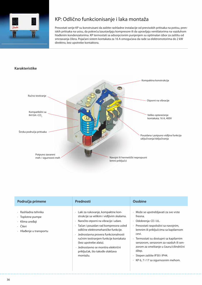
ISO 9001 quality approval Danfoss A/S is certifi cated by BSI in accordance with international standard ISO 9001. This means that Danfoss fulfi ls the international standard in respect of product development, design, production and sale. BSI exercises continuous inspection to ensure that Danfoss observes the requirements of the standard and that Danfoss’ own quality assurance system is maintained at the required level.
KP/KPI illustrated is KPI 35with top cover
Danfoss KP/KPI pressure switches are used for regulating, monitoring and alarm systems in industry.KP pressure switches are recommended for gaseous media (also water, but only when mounted directly on the pipe - do not use capillary tube mounting).
Description
Features • Wide regulating range• Can be used for pumps and compressors• Small dimensions. Space-saving – easy to install in panels• Shock and impact resistant• Ultra-short bounce times. Limits wear to an absolute minimum and increases reliability• Electrical connection from front of unit. Makes rack mounting easier and also saves space• Suitable for both alternating current and direct current• Cable entry for 6-14 mm diameter cables• Screwed cable entry makes rewiring easy. Standard screwed cable entry Pg 13.5 and Pg 16
KPI pressure switches are suitable for plant in connection with liquid and gaseous media.The pressure switches are fi tted with a single-pole switch changeover (SPDT). The position of the switch depends on the setting of the pressure control and the pressure in the connector.
Defi nitions Range settingThe pressure range within which the unit will give a signal (contact changeover).
Diff erentialThe diff erence between contact changeover on rising and falling pressure.The diff erential is a condition for stable automatic plant operation.
Automatic resetUnits with automatic reset restart automatically after stop.Min. reset units will restart after the pressurehas risen by a value greater than that of the fi xed diff erential.Max. reset units will restart after the pressurehas fallen by a value greater than that of the fi xed diff erential
Permissible operating pressureThe highest permissible constant pressure or pressure variation the unit can be exposed to.

−0.2 → 7.5 0.7 → 4 17 22 G ¼ AAg 060-113366
KP 35Au 060-504766
2 → 14 0.7 → 4 17 22 G ¼ AAg 060-110866
KP 36Au 060-113766
4 → 12 0.5 → 1.6 17 22 G ¼ AAg 060-122166
KP 36Au 060-114466
−0.2 → 8 0.4 → 1.5 18 18 G ¼ AAg 060-121766
KPI 35Au 060-316466
−0.2 → 8 0.5 → 2 18 18 G ¼ A Ag 060-121966 KPI 35
4 → 12 0.5 → 1.6 18 18 G ¼ AAg 060-118966
KPI 36Au 060-113866
2 → 12 0.5 → 1.6 18 18 G ¼ A Ag 060-316966 KPI 36
8 → 28 1.8 → 6 30 30 G ¼ A Ag 060-508166 KPI 38
Data sheet Pressure switches and thermostats, types KP and KPI
IC.PD.P10.F1.02 - 520B2008 3
Ordering Pressure switches type KP 35 and 36Setting
range pe
[bar]
Diff erential
[bar]
Permissible operating
pressure pe
[bar]
Max. test pressure
[bar]
Pressure connection
Contact material
Code no. Type
Pressure switches type KPI 35 - 38Setting
range pe
[bar]
Diff erential
[bar]
Permissible operating
pressure pe
[bar]
Max. test pressure
[bar]
Pressure connection
Contact material
Code no. Type
Description KP 35, 36 KPI 35, 36 KPI 38
Ambient temperature°C –40 °C - +65 °C (for short periods up to +80 °C)
Media temperature °C –40 °C - +100 °C
Media
Gaseous media (also water, but only when mounted directly on the pipe - do not use capillary tube mounting).
Gaseous media and liquids
Parts in contactwith medium
BellowsTinbronze W.no. 2.1020 to DIN 17662
Tinbronze W.no. 2.1020 to DIN 17662
Pressure connectorFree-cutting steel (nickel plated) W. no. 1.0737 to EN 10277-3
Brass W. no. 2.0401 to DIN 17660Free-cutting steel (nickel plated) W. no. 1.0737 to EN 10277-3
Contact systemSingle-pole changeover switch (SPDT)
Contact load, Ag contact set
Contact material AgCdO
Alternting current:AC-1: 16 A, 400 VAC-3: 16 A, 400 VAC-15: 10 A, 400 VDirect current:DC-13 12 W, 220 V
Alternating current:AC-1: 10 A, 440 VAC-3: 6 A, 440 VAC-15: 4 A, 440 VDirect current:DC-13 12 W, 220 V
Contact load, Au contact set See information page 4
Enclosure, IP 33 grade Unit must be mounted on a fl at surface/ a fl at fi tting and all unused holes covered
Enclosure, IP 44 grade Mounted as IP 33 plus fi tting of top cover, code no. 060-109766
Cable connection Entry for 6-14 mm diameter cables
Mounted on back plate/ wall bracket Vibration proof in the range 0 to 1000 Hz, 4 g ( 1 g = 9.81 m/s2)
Mounted on angle bracket Not recommended in areas where vibrations occur
Approvals
EN 60 947-4,5RINA, Registro Italiano NavaleRMRS, Maritime Reg. of Shipping, RussiaUL approved version are availableCCC, China Compulsory Certifi cate
EN 60 947-4,5
Technical data

4 IC.PD.P10.F1.02 - 520B2008
Data sheet Pressure switches and thermostats, types KP and KPI
Setting KP/KPI pressure switches with automatic reset:Set the upper limit pressure on the range scale
Then set the lower limit pressure on the DIFF scale (the upper limit minus the diff erential).
Gold contacts Contact systemSingle-pole changeover switch (SPDT) Contact material: Gold-plated silver
Contact load (when Au surface is burnt away)Alternating current:Ohmic load: AC-1: 10 A, 440 V Inductive load: AC-3: 6 A, 440 V AC-15: 4 A, 440 V
Direct current: DC-13 12 W, 220 V,
Curve A gives the maximum load. Hatched area B: Acceptable load for the gold plating of the contact.

Data sheet Pressure switches and thermostats, types KP and KPI
IC.PD.P10.F1.02 - 520B2008 5
Design and function
1. Setting spindle 2. Diff erential setting spindle 3. Main arm 4. Main spring 5. Diff erential spring
6. Bellows 7. Connector 8. Contact system 9. Connection terminals 10. Earth terminal
11. Cable entry 12. Omega spring (KPI)12. Tumbler (KP) 13. Locking screw (KPI)13. Locking plate (KP)
Drawing showing principle of KP pressure switches
Drawing showing principle of KPIpressure switches
KP features The contact system in KP pressure switches has a snap function. This means that the bellows is active only when the cut-in or cut-out value is reached.The bellows is connected to the pressure of the controlled plant via the connector (7).
The design of KP pressure switches gives the following advantages:
• High contact load• Ultra-short bounce times• Vibration-proof in the range 0-1000 Hz, 4 g (1 g = 9.81 m/s2)• Long operating life• High pulsation protection• Small dimensions – Easy to mount in panels
KPI features Danfoss KPI pressure switches are designedso that the bellows moves in the sameproportion as the pressure change.To ensure a snap function on contact change-over, an omega spring is located between bellows and contact system.
The design of KPI pressure switches gives the following advantages:
• High contact load• Ultra-short bounce times• Vibration-proof in the range 0-1000 Hz, 4 g (1 g = 9.81 m/s2)• Long operating life• Can be used for both liquids and gases• Small dimensions – Easy to mount in panels
6 IC.PD.P10.F1.02 - 520B2008
Data sheet Pressure switches and thermostats, types KP and KPI
Dimensions and weights
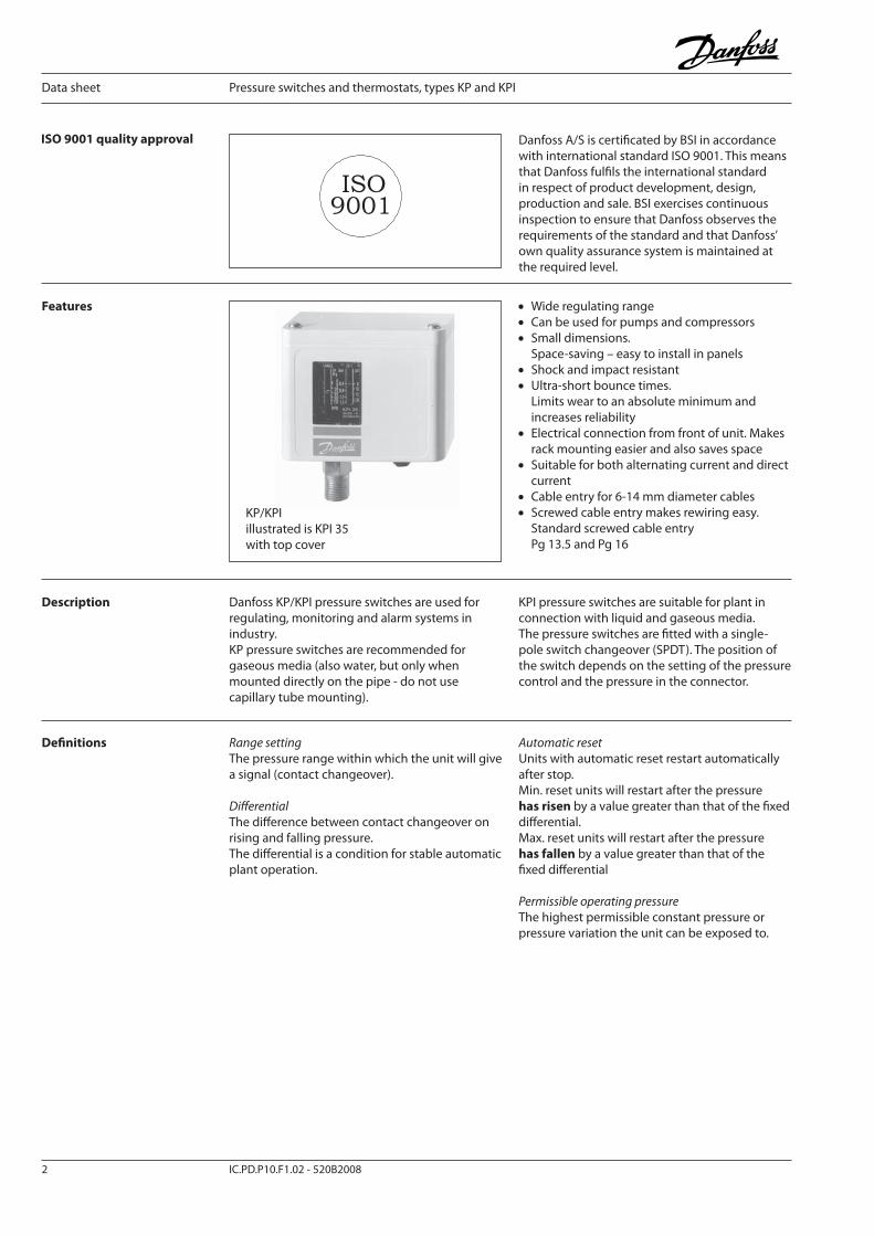
Pressure switches KP 35, KP 36, KPI 35, KPI 36 and KPI 38:Weight approx. 0.3 kg
Accessories for KP/ KPI pressure switches
Part Symbol Description Total Code no.
Brackets with mounting screws and washers
Wall bracket 10 060-105566
Angle bracket 10 060-105666
Screwed cable entry
Screwed cable entryPg 13.5 with special nutfor 6-14 mm cablesA standard Pg 16 screwed cable entry can be used for 8-16 mm cables
5 060-105966
Sealing screw For sealing the setting on KP 20 060-105766
Top cover
If a bracket is mounted on the bracketplate of the housing, the KP/KPI pressure switch will have an IP 44 grade of enclosure. The cover covers the setting spindles
10 060-109766
Protective cap
Protective cap for KP/KPI pressure switches.To protect the unit against rain and humidity.Grade of enclosure: IP 44Material: PolyethyleneMax. ambient temperature: 65°CMin. ambient temperature: −40°C
7 060-003166

KP 44
Data sheet Pressure switches and thermostats, types KP and KPI
IC.PD.P10.F1.02 - 520B2008 7
Features • Wide regulating range• Can be used for pumps and compressors• Small dimensions. Space-saving – easy to install in panels• Ultra-short bounce times. Limits wear to an absolute minimum and increases reliability• Electrical connection from front of unit. Makes rack mounting easier and also saves space• Suitable for both alternating current and direct current• Cable entry for 6-14 mm diameter cables• Screwed cable entry makes rewiring easy. Standard screwed cable entry Pg 13.5 and Pg 16• Effi cient protection of water pumps in case of water supply fails.
The lefthand pressure bellows switches the pump pressure. The righthand bellows cuts out the pump if the pump suction pressure is too low. In this way the pump is protected from running dry and consequent bearing damage.
Danfoss dual pressure switch KP 44 is designed for use as a pump guard to control and protect supply water pumps. The KP 44 pump guard combines the function of a pressure switch and a fl ow monitoring device.
Description
Defi nitions Range settingThe pressure range within which the unit will give a signal (contact changeover).
Diff erentialThe diff erence between contact changeover on rising and falling pressure.The diff erential is a condition for stable automatic plant operation.
Automatic resetUnits with automatic reset restart automatically after stop.Min. reset units will restart after the pressurehas risen by a value greater than that of the fi xed diff erential.
Max. reset units will restart after the pressurehas fallen by a value greater than that of the fi xed diff erential
Permissible operating pressureThe highest permissible constant pressure or pressure variation the unit can be exposed to.
Pressure switch type KP 44, IP 22
Pressure range Diff erential Permissible operating
pressure pe
[bar]
Max. testpressure
[bar]
Pressure connection
Contactmaterial
Code no.Control[bar]
Safety[bar]
Control[bar]
Safety[bar]
2 → 12 0.5 → 6 0.7 → 4.0 1.0 LP/HP: 17 22 2 × G ¼ A Ag 060-001366
Ordering

8 IC.PD.P10.F1.02 - 520B2008
Data sheet Pressure switches and thermostats, types KP and KPI
Technical data Ambient temperature °C −40°C to +65°C (for short periods up to +80°C)
Media temperature °C Max. + 100°C
Media Fresh water
Parts in contactwith media
Bellows Tinbronze W.no. 2.1020 to DIN 17662
Pressure connector Free-cutting steel (nickel plated) W. no. 1.0737 to EN 10277-3
Contact material AgCdO
Alternating current:AC-1: 16 A, 400 VAC-3: 16 A, 400 VAC 15: 10 A 400 V
Direct current:DC-13: 12 W, 220 V
Approvals EN 60 947-4.-5
Cable connection Entry for 6-14 mm diameter cables
Mounted on backplate or wall bracket Vibration-proof in the range 0-1000 Hz, 4g (1g = 9.81m/s2)
Mounting on angle bracket Not recommended for areas where vibration occurs

Data sheet Pressure switches and thermostats, types KP and KPI
IC.PD.P10.F1.02 - 520B2008 9
Design and function 1. Lefthand pressure setting spindle 2. Diff erential setting spindle 3. Main arm 4. Righthand pressure setting spindle 5. Main spring 6. Diff erential spring 7. Bellows 8. Pressure connections 9. Switch 10. Terminal 11. Earth terminal 12. Cable entry13. Tumbler14. Locking plate15. Impulse lever
The switch in the KP has a snap-action function, and the bellows moves only when the cut-in or cut-out value is reached.
Water supply from reservoir or well If water is running short in the well or reservoir, the pump will no longer be able to increase the pressure to the cut-out value. Consequently the pump will keep running - perhaps without water. However, the KP 44 pump guard will stop the pump as soon as the righthand bellows pressure drops below the safety cut-out setting.
The pump can be started again by lifting the impulse lever. The pump will continue to operate when the impulse lever is released, provided that the righthand bellows pressure is higher than the safety cut-out setting plus a fi xed diff erential of 1 bar. If this is not the case, the pump will cut-out again indicating insuffi cient water supply.
Pressurized water supply direct to pumpWhen water supply fails on the inlet side, the pump will no longer be able to boost the pressure to the cut-out value. Consequently the pump will keep running - perhaps without water. However, the KP 44 pump guard will stop the pump as soon as the pressure in the pump suction line drops below the safety cut-out setting. The pump will automatically start again when the pump suction pressure has reached the level of 1 bar above the safety cut-out setting.
Automatic start-up will only take place if the righthand bellows is connected to the pump suction line. Air pockets should be avoided to prevent the pump from starting up on air pressure rise, without the presence of water.
In a hydrophore system where water is pumped from a well or an open tank, both bellows are connected to a pressure outlet on the air side in the pump pressure line, if possible.
In a booster system receiving pressurized water the righthand bellows is connected- to the low pressure side of the pump for automatic start-up.- to the high pressure side of the pump for manual start-up.The lefthand bellows is always connected to the high pressure side of the pump.

10 IC.PD.P10.F1.02 - 520B2008
Data sheet Pressure switches and thermostats, types KP and KPI
Pressure settings Safety cut-out settingThe righthand bellows will automatically cut-out the pump at the safety cut-out setpoint. Automatic start-up, if any, will take place when the pressure has reached the level of 1 bar above the setpoint. Manual cut-in is made by lifting the impulse lever and releasing it again when the pressure has increased by min. 1 bar.
The safety cut-out setpoint is normally determined by the static pressure (the water column). However, in order to avoid disturbing signal interaction, care should be taken to ensure that the safety cut-out setting is at least 1.5 bar lower than the control pressure cut-in setting. See table with pressure setting examples below.
Required tap water pressure ≥2.3 bar ≥4.0 bar ≥5.0 bar ≥8.0 bar
Control pressure cut-out setting 3.0 bar 5.0 bar 8.0 bar 12 bar
Diff erential 0.7 bar 1.0 bar 3.0 bar 4.0 bar
Control pressure cut-in setting 2.3 bar 4.0 bar 5.0 bar 8.0 bar
Max. safety cut-out setting 0.8 bar 2.5 bar 3.5 bar 6.0* bar
* 6.0 bar is the normal max. setpoint
Control pressure settingsControl pressure cut-out setpoint is set on the lefthand pressure setting scale.
The diff erential is set between 0.7 and 4 bar.The control pressure cut-in setting will be the cut-out control pressure less the diff erential.
Accessories for KP 44 pressure switches
Part Symbol Description Total Code no.
Brackets with mounting screws and washers
Wall bracket 10 060-105566
Angle bracket 10 060-105666
Screwed cable entry
Screwed cable entryPg 13.5 with special nutfor 6-14 mm cablesA standard Pg 16 screwed cable entry can be used for 8-16 mm cables
5 060-105966
Sealing screw For sealing the setting on KP 20 060-105766
Dimensions and weight
Weight approx. 0.5 kg

Data sheet Pressure switches and thermostats, types KP and KPI
IC.PD.P10.F1.02 - 520B2008 11
• Wide regulating range
• Small dimensions Space-saving - easy to install in panels
• Ultra-short bounce time. Limits wear to an absolute minimum and increases reliability.
• Electrical connection at front of unit. Makes rack mounting easier and also saves space
• Suitable for both alternating current and direct current
• Cable entry for 6-14 mm diameter cables
• Screwed cable entry makes rewiring easy
• Standard screwed cable entry Pg 13.5 and Pg 16
Danfoss KP thermostats are used for regulating, monitoring and alarm systems in industry.KP thermostats are temperature-operated electric circuit breakers. The thermostats are fi tted with a single-pole switch (SPDT)
The position of the switch depends on the thermostat setting and sensor temperature. A KP thermostat can be connected and switch to single-phase alternating current motors of up to about 2 kW.
Description
Diff erentialThe diff erence between cut-in and cut-out temperature. The diff erential is a condition for stable automatic plant operation.
Mechanical diff erential (intrinsic diff erential)The diff erential set on the diff erential spindle of the unit.
Working diff erential (thermal diff erential)The diff erential on which the plant operates. The working diff erential is the sum of the mechanical diff erential and the diff erential arising from the time constant.
Reset1. Manual reset. Resets only when the reset button is pressed. Min. reset units will restart after the temperature at the thermostat sensor has risen by a value greater than that of the fi xed diff erential. Max. reset units will restart after the temperature at the thermostat sensor has fallen by a value greater than that of the fi xed diff erential
2. Automatic reset. Units with automatic reset restart automatically after stop.
Features
Defi nitions

12 IC.PD.P10.F1.02 - 520B2008
Data sheet Pressure switches and thermostats, types KP and KPI
Setting range
[C°]
Diff erential
[C°]
Max. sensor temperature
[C°]
Capillary tube length
m
Contact material Code no. Type
0 → 40 3 → 10 80 Room sensorAg 060L121266
KP 75Au 060L117166
30 → 90 5 → 15 150 2 Ag 060L118466 KP 78
50 → 100 5 → 15 150 2 Ag 060L112666 KP 79
80 → 150 7 → 20 200 2 Ag 060L112566 KP 81
80 → 150 7 → 20 200 3 Ag 060L118366 KP 81
80 → 150 7 → 20 200 5 Ag 060L117066 KP 81
80 → 150 8 (max. reset) 200 2 Ag 060L115566KP 81
(max. reset)
Ordering Thermostats type KP 75 - KP 81
Ambient temperature °C –40 °C - +65 °C (for short periods up to +80 °C)
Sensor material Tinned copper Cu/Sn5
Contact system
Single-pole changeover switch (SPDT)
Contact load, Ag contact set
Contact material AgCdO
Alternating current:AC-1: 16 A, 400 VAC-3: 16 A, 400 VAC-15: 10 A, 400 V
Direct current:DC-13: 12 W, 220 V
Contact load, Au contact set See Information page 14
Enclosure, IP 33 grade Unit must be mounted on a fl at surface / a fl at fi tting and all unused holes covered
Enclosure, IP 44 grade Mounted as IP 33 olus fi tting of top cover, code no. 060-109766
Approvals EN 60 947-4. -5RINA, Registro Italiano NavaleRMRS, Maritime Reg. of Shipping, RussiaBureau VeritasGermanischer Lloyd, GermanyDNV, Det Norske Veritas, NorwayUL approved version are availableCCC, China Compulsory Certifi cate
Cable connection Entry for 6-14 mm diameter cable
Mounted on backplate or wall bracket Vibration-proof in the range 0-1000 Hz, 4 g (1 g = 9.81 m/s2)
Mounted on angle bracket Not recommended for areas where vibration occurs
Technical data

KP 78, KP 79, KP 81
Data sheet Pressure switches and thermostats, types KP and KPI
IC.PD.P10.F1.02 - 520B2008 13
Design and function
1. Temperature setting spindle2. Diff erential setting spindle3. Main arm7. Main spring8. Diff erential spring9. Bellows12. Contact system13. Connection terminals14. Earth terminal15. Cable entry16. Tumbler17. Sensor
Drawing showing principle of KP thermostats
KP 75 room sensor
The contact system in KP thermostats has a snap function. This means that the bellows is active only when the cut-in or cut-out value is reached.
The design of KP thermostats gives the following advantages:
• High contact load • Ultra-short bounce times. Limits wear to an absolute minimum and increases reliability.• Vibration-proof in the range 0-1000 Hz, 4 g (1 g = 9.81 m/s2)• Long operating life
Setting Thermostats with automatic resetSet the upper limit temperature on the range scale. Then set the diff erential on the DIFF scale.The temperature set on the range scale is also the temperature at which contact changeover re-occurs on rising temperature.The contacts changeover when the temperature has fallen to a value lower than that set on the DIFF scale.If at lower settings the plant will not start/stop, the reason might be that the diff erential has been set too high.
Thermostats with minimum resetSet the temperature on the range scale. The diff erential setting is fi xed. Min. reset units will restart after the temperature at the thermostat sensor has risen by a value greater than that of the fi xed diff erential.
Thermostats with maximum resetSet the stop temperature on the range scale. The diff erential setting is fi xed. Max. reset units will restart after the temperature at the thermostat sensor has fallen by a value greater than that of the fi xed diff erential

14 IC.PD.P10.F1.02 - 520B2008
Data sheet Pressure switches and thermostats, types KP and KPI
Charges Absorption chargeThe charge consists partly of a superheated gas and partly of a solid substance with a large absorption surface.The solid substance is concentrated in the sensor (17), and consequently it is always the sensor that comprises the temperature-regulating part of the thermostatic element.The sensor can be placed both warmer or colder than the thermostat housing and capillary tube. However, placing it in an ambient temperature higher or lower than +20 °C can aff ect the accuracy of the scale.
9. Bellows19. Capillary tube17. Sensor
Gold contacts Contact systemSingle-pole changeover switch (SPDT) Contact material: Gold-plated silver
Contact load (when Au surface is burnt away)Alternating current: Ohmic load: AC-1: 10 A, 440 V Inductive load: AC-3: 6 A, 440 V AC-15: 4 A, 440 V
Direct current: DC-13: 12 W, 220 V
Curve A gives the maximum load. Hatched area B: Acceptable load for the gold plating of the contact.

Data sheet Pressure switches and thermostats, types KP and KPI
IC.PD.P10.F1.02 - 520B2008 15
Dimensions and weight
Thermostats KP 75, KP 78, KP 79, KP 81Weight approx. 0.4 kg
KP 75Sensor: Tinned copper Cu/Sn 5
KP 78, 79, 81Sensor: Tinned copper Cu/Sn 5
Wall bracket Angle bracket

16 IC.PD.P10.F1.02 - 520B2008
Data sheet Pressure switches and thermostats, types KP and KPI
Part Symbol Description Total Code no.
Brackets with mounting screws and washers
Wall bracket for KP
Angle bracket for KP
10
10
060-105566
060-105666
Capillary tube gland
Oil-resistant rubber gasket for max. 110°C and 90 bar5 060-422066
Sensor holderSensor holder for wall mounting with four capillary tube clips and 9-off 12 mm pins
20 017-420166
Knob 20 060-106366
Screwed cable entry
PG 13.5 with special nutFor 6-14 mm diameter cablesA standard Pg 16 cable entry can be used for 8-16 mm diameter cables
5 060-105966
Sealing screwFor sealing the setting on KP
20 060-105766
Top cover
If a bracket is mounted on the backplate of the housing, the KP thermostat will have an IP 44 grade of enclosure. The cover protects the setting spindles.
10 060-109766
Protective cap
Protective cap for KP thermostats.To protect the unit against rain and humidity.Grade of enclosure: IP 44Material: PolyethyleneMax. ambient temperature: 65°CMin. ambient temperature: −40°C
7 060-003166
Sensor pocket
Permissible pressure of sensor pipe medium
For all KP thermostats with cylindrical remote sensor. Sensor pocket, gasket and union for screwing into G½ connectors welded onto tues, containers, etc.
Int. diameter 9.6 mm, insert depth 112 mm (brass). Ext. diameter 11 mm
Int. diameter 9.6 mm, insert depth 112 mm (st 18/8). Ext. diameter 11 mm
Int. diameter 9.6 mm, insert depth 465 mm (brass). Ext. diameter 11 mm
Media temperature for sensor : 250 °CThis temperature can be increased by applying a diff erent gasket material
1
1
1
017-437066
017-436966
017-421666
Heat-conductive aluminium paste
Tube
For KP and RT thermostats with sensor mounted in a sensor pocket. Temperature range: −20 to 150°C (short-lived + 220°C)
Tube with 5 g aluminium paste 1 041E0114
Accessories for KP thermostats
Brass Stainless steel
Accessories for KP thermostats

® D
anfo
ss A
/S 0
3-05
/ IC
-MC
/mr
17 IC.PD.P10.F1.02-520B2008
Data sheet Pressure switches and thermostats, types KP and KPI
IP 33/44 enclosure IP 33 grade of enclosure is obtained by mounting the unit on a fl at surface or a fl at fi tting and then covering all unused holes. IP 44 grade of enclosure is obtained by mounting the unit as for IP 33 grade of
enclosure and then fi tting a top cover, code no. 060-109766. Alternatively the unit can be mounted in a poly-ethylene protective cap, type no. 060-003166.
IP 1st digit Foreign body test IP 2nd digit Watertightness test 1)
0 No test 0 No test
1 A ball of ∅50 mm cannot enter 1 Vertically falling drops, dripping water
2 A ball of ∅12.5 mm and a test probe of ∅12 mm, L = 80 mm, cannot be inserted 2 Vertically (±15°) falling drops
3 A rod of ∅2.5 mm cannot enter 3 Water sprays ±60° from vertical
4 A wire of ∅1 mm cannot enter 4 Water sprays from all directions
5 As 4 + Dust in amounts that might cause damage cannot enter 5 Water jets from all directions, 12 l/mm
6 As 4 + Dust cannot enter 6 Water jets from all directins, 100 l/mm
7 Immersion in 1 m water
8 Subject to agreement
1) After all these tests, water in amounts that might cause damage must not have entered the enclosure and not have collected in electrically conductive parts or cable entries.
An IP grade of enclosure certifi cation is obtained when the product has been sub-mitted to an IP test. The IP classifi cation contains two digits, the fi rst IP digit denoting
the degree of enclosure against foreign bodies, the second digit denoting the degree of watertightness. The corresponding tests are as follows:
IP testing

38
Područja primene Prednosti Osobine
ACB: Patronski presostati
Patronski presostati serije ACB, su mali cilindrični presostati proizvedeni u fabrici Danfoss Saginomiya u
Poljskoj. Glavne faze procesa proizvodnje ovih presostata se izvode uz primenu preciznih tehnoloških
postupaka u proizvodnji, u apsolutno čistim sobama. Ovime se obezbeđuje da se karakteristike
proizvoda mogu garantovati tokom dužeg perioda, obezbeđujući pouzdan rad tokom čitavog radnog
veka proizvoda.
· Rashladna tehnika
· Toplotne pumpe
· Klima uređaji
· Čileri
· Hlađenje u transportu
· Kompaktni i laki za montažu
· Odlična pouzdanost i moć ponavljanja
· Širok izbor promenljivih: zadata vred-
nost priključak za pritisak, električni
priključak
· Fleksibilne količine za poručivanje
usled proizvodnje u Evropi sa kratkim
vremenom isporuke
· Dostupni širom sveta i rasprostranjena
upotreba kod svih velikih proizvođača
· Preko 100 miliona komada u eksploat-
aciji
· CE, TÜV, VDE, UL i C-UL odobrenja
(SPDT ručni reset samo CE odobrenja)
· Kontaktno opterećenje do 6 A
(250 V AC)
· Normalno zatvoren (NC), Normalno
otvoren (NO) ili SPDT kontaktni sistem
· Priključak na buksu ili kablovi (stand-
ardnom isporukom je predviđen 1,5 m
kabla)
· Opseg pritisaka od - 0,50 bar do 45 bar
· Automatski i ručni reset
· Izrađuju se u zaštiti IP 65 (verzija
otporna na vodu sa kablovima) i IP40
(verzija sa priključcima na buksnu)
Karakteristike
provodnici
dugme za reset
kućište otporno na vodu
dijafragma
priključak za pritisak
(1/4” unutrašnji navoj)
stezaljka (električna)
mikro-prekidač
osovina prigušna iglaSlika: tip SPST ručni reset

39
Patronski presostati – ACB
Tehnički podaci i poručivanje
Standardni patronski presostati
Područje
primeneReset
Isključenje Uključenje Kontaktni sistem/
stepen zaštite:
W-otporan na
vodu1)
S-sa buksnom 2)
Priključak
bar barLemni 1/4”
unutrašnji
navoj 6mm 1/4”
Visoki
pritisak
isključi-
vanje
automatski 18 ± 0,7 13 ± 1,2
SPST-NC / W 061F7504 061F7505 061F7506
SPST-NC / S - 061F8711 061F8709
SPDT / W - - 061F9057
automatski 20 ± 1,0 16 ± 1,5 SPST-NC / S - 061F8710 061F8708
automatski 23 ± 1,0 19 ± 1,5 SPST-NC / S - 061F8707 061F8703
automatski
23 ± 0,7 19 ± 1,2
SPST-NC / W - - 061F8494
SPDT / W- - 061F9056
ručni - - 061F9243
automatski
26 ± 1,0 20 ± 1,5
SPST-NC / W 061F7507 061F7508 061F7509
SPST-NC / S - 061F8705 061F8701
automatskiSPDT / S - 061F9104 061F9100
SPDT / W - - 061F9055
ručni 26 ± 1,0 20 ± 2,0 SPST-NC / W 061F9703 061F9714 061F9713
automatski
28 ± 1,0 21 ± 1,5
SPST-NC / W 061F7510 061F7513 061F7514
automatski SPST-NC / S - 061F8704 061F8700
automatskiSPDT / W - - 061F9054
SPDT / S - 061F9107 061F9103
ručni SPDT / W - - 061F9242
ručni 28 ± 1,0 21 ± 2,0 SPST-NC / W - - 061F9522
automatski 31 ± 1,0 24 ± 1,5
SPST-NC / W 061F8493 - 061F8492
SPST-NC / S - 061F8706 061F8702
SPDT / W - - 061F9053
automatski
42 ± 1,2 33 ± 2,0SPST-NC / W
061F7515 061F7516 061F7517
ručni - - 061F9575
automatski SPDT / W - - 061F9052
Nizak
pritisak
isključi-
vanje
automatski
0,5 ± 0,4 1,5 ± 0,3 SPST-NO / W 061F7518 061F7519 061F7520
0,5 ± 0,5 1,5 ± 0,5SPST-NO / S - 061F7402 061F7400
SPDT / S - 061F9106 061F9102
automatski
0,7 ± 0,5 1,7 ± 0,4SPST-NO / W 061F7521 061F7522 061F7523
SPDT / W - - 061F9058
0,7 ± 0,5 1,7 ± 0,5SPST-NO / S - 061F7403 061F7401
SPDT / S - 061F9105 061F9101
automatski 1,7 ± 0,5 2,7 ± 0,4 SPST-NO / W 061F7524 061F7525 061F7526
Kontrola
ventilatora automatski
8,5 ± 1,2 11 ± 0,8
SPST-NO / W
061F8491 - 061F8490
13 ± 1,5 16 ± 1,0 061F8334 - 061F8333
1) Modeli otporni na vodu (IP 65) sa 1,5 m kabla AWG18, pakovani po 20 komada 2) Modeli sa priključkom na buksnu (IP 40), pakovani po 50 komada

40
Područja primene Prednosti Osobine
UT: Jednostavna i laka regulacija temperature
UT termostat je temperaturno upravljani termostat sa kapilarnom cevi i davačem od nerđajućeg čelika
(18/8) ili bakra. Temperatura mora biti podešena na odgovarajuću traženu srednju vrednost. Termostat
ima fi ksnu diferencu.
Karakteristike
· Rashladne komore
· Vitrine za hlađenje pića
· Uređaji za pravljenje sladoleda
· Laktofrizi
· Rashladne vitrine
· Klima uređaji
· Instalacije sa rekuperacijom toplote
· UT je moguće poručiti za zidnu ili
panelnu ugradnju
· UT za zidnu ugradnju:
IP 20 to EN 60529/IEC 52
· UT za panelnu ugradnju:
IP 00 to EN 60529/IEC 529
· UT 72 za univerzalnu upotrebu
-30 to 30°C
· UT 73 za zaštitu od smrzavanja
0 to 40°C
· Diferenca je fi ksna 2.3°K
· Automatski reset
· Opterećenje kontakta:
- AC 1: 10 A, 250/380 V (omski)
- AC 11: 2.5 A, 250/380 V (induk.)
Temperatura može biti podešena
lako i precizno korišćenjem velikog
točka na prednjoj strani termostata.
Električni priključci su kablovske
priključnice i konektori sa zavrtnjem
Kontaktni sistem:
Prekidač za prebacivanje (SPDT)
Kapilarna cev od bakra ili čelika 18/8
Davač od bakra ili čelika 18/8

41
Termostati – UT
Tehnički podaci i poručivanje
Verzija TipOpseg
°C
Diferenca
KReset
Maks.
temperatura
davača
°C
Dužina
kapilarne
cevi
m
KoličinaPorudžbeni broj
Bakar 18/8
Zidna
ugradnja
UT 72 –30 30 2.3 aut. 60 1.5 1 060H1101 060H1106
UT 72 –30 30 2.3 aut. 60 1.5 1 060H11031)
UT 72 –30 30 2.3 aut. 60 1.5 20 060H1104
UT 72 –30 30 2.3 aut. 60 3.0 1 060H1105
UT 73 0 40 2.3 aut. 90 1.5 1 060H1102
Panelna
ugradnja
UT 72 –30 30 2.3 aut. 60 1.5 48 060H1201
UT 72 –30 30 2.3 aut. 60 3.0 48 060H1205
UT 73 0 40 2.3 aut. 90 1.5 48 060H1202
1) Uključujući vezice davača
Dodatna oprema
Količina UT 72 UT 73
Točak za podešavanje 48 060-1067 060-1096
Vezica davača 36 060-1090 060-1090

42
Područja primene Prednosti Osobine
RT: Presostati i termostati
Serija RT obuhvata termostate i presostate za sve vrste primena u industrijskom i brodskom hlađenju.
Rad RT termostata odgovara radu jednopolnog prekidača. Položaj kontakata zavisi od temperature
davača i i zadate vrednosti na skali. RT presostat sadrži pritiskom upravljani jednopolni prekidački kon-
takt, čiji položaj zavisi od pritiska u ulaznom priključku i zadate vrednosti na skali.
· Sve vrste primena u industrijskom i
brodskom hlađenju
· Širok opseg regulacije
· Podesni za naizmeničnu i jednosmer-
nu struju
· Zamenljivi sistem kontakata
· Specijalne verzije sa zlatom
prevučenim kontaktnim površinama
za primenu u PLC
· Verzije regulatora sa neutralnom
zonom
· Vodootporne verzije, stepen zaštite
IP 66
· Visoka postojanost i tačnost
· Dug radni vek
· Stepen zaštite: IP 66 do EN 60529 /
IEC 60529, osim za verzije sa spolj.
resetom koji su sa zaštitom do IP 54
· Zaštita od kratkog spoja, osigurač 10 A
· Izolacija 400 V
· Temperatura okoline: -50 do +70°C za
kućište
· Kablovski uvodnik: Pg 13.5.
· Prečnik kabla: 6 14 mm.
· Presostati za freone i R717 (NH3)
Karakteristike
Točak za podešavanje
Kućište za otežane uslove rada
Kontrolni sistem visoke preciznosti
Meh od nerđajućeg čelika
Kablovski uvodnik Pg 13.5
Ožičenje 0.2 do 2.5 mm2
Zamenljivi SPDT
kontaktni sistem
Stepen zaštite IP 66

43
Presostati i termostati – RT
Tip davača / senzora
A B C D
Cilindrični
daljinski senzor
Prostorijski senzor Kanalski senzor Kapilarni sensor
Tehnički podaci i poručivanje: RT termostati
Tip punjenja Tip Tip davača Opseg
regulacije
Diferenca t Reset Maks.
temp. davača
Dužina
kapilarne
cevi
Porudžbeni
broj
°C
Najniža
temp.
podešavanja
K
Najviša
temp.
podešavanja
K °C m
Parno 1)
RT 10 A -60 -25 1.7 7.0 1.0 3.0 aut. 150 2 017-507766
RT 9 A -45 -15 2.2 10.0 1.0 4.5 aut. 150 2 017-506666
RT 3 A -25 +15 2.8 10.0 1.0 4.0 aut. 150 2 017-501466
RT 17 B -50 -15 2.2 7.0 1.5 5.0 aut. 100 017-511766
RT 11 B -30 0 1.5 6.0 1.0 3.0 aut. 66 017-508366
RT 4 B -5 +30 1.5 7.0 1.2 4.0 aut. 75 017-503666
017-5037664)
Adsorpci-
ono 2)
RT 13 A -30 0 1.5 6.0 1.0 3.0 aut. 150 2 017-509766
RT 2 A -25 +15 5.0 18.0 6.0 20.0 aut. 150 2 017-500866
RT 8 A -20 +12 1.5 7.0 1.5 7.0 aut. 145 2 017-506366
RT 12 A -5 +10 1.0 3.5 1.0 3.0 aut. 65 2 017-508966
RT 23 A +5 +22 1.1 3.5 1.0 3.0 aut. 85 2 017-527866
RT 15 A +8 +32 1.6 8.0 1.6 8.0 aut. 150 2 017-511566
RT 24 A +15 +34 1.4 4.0 1.4 3.5 aut. 105 2 017-528566
RT 140 C +15 +45 1.8 8.0 2.5 11.0 aut. 240 2 017-523666
RT 102 D +25 +90 2.4 10.0 3.5 20.0 aut. 300 2 017-514766
RT 34 B -25 +15 2.0 10.0 2.0 12.0 aut. 100 017-511866
RT 7 A -25 +15 2.0 10.0 2.5 14.0 aut. 150 2 017-505366
RT 14 A -5 +30 2.0 8.0 2.0 10.0 aut. 150 2 017-509966
RT 101 A +25 +90 2.4 10.0 3.5 20.0 aut. 300 2 017-500366
Delimično 3) RT 107 A +70 +150 6.0 25.0 1.8 8.0 aut. 215 2 017-513566
1)Davač mora biti postavljen na hladnijem mestu od kućišta termostata i kapilarne cevi. 2) Davač može biti postavljen na toplijem ili hladnijem mestu u odnosu na kućište
termostata. 3) Davač mora biti postavljen na toplijem mestu od kućišta termostata i kapilarne cevi. 4) Sa ugrađivenim grejačem redukuje se temperaturna diferenca.

44
Diferencijalni presostati za R 717(NH3) i freone
Tip Opseg regulacije
bar
Diferenca
p
bar
Radni opseg
za LP meh
bar
Maks.
radni
pritisak
PB
bar
Maks.
ispitni
pritisak p’
bar
Porudžbeni broj
Priključak
rezni prsten
6 mm
G 3/8 A 1)+ nipl
na zav.
6.5/10 mm
RT 260A
0.5 4 fi ksna 0.3 -1 18 22 25 017D001466 017D002166
0.5 4 fi ksna 0.3 -1 18 22 25 017D0022662)
0.5 6 fi ksna 0.5 -1 36 42 47 017D001566 017D002366
1.5 11 fi ksna 0.5 -1 31 42 47 017D001666 017D002466
RT 252A 0.1 1.5 fi ksna 0.1 -1 9 22 13 017D001366 017D002566
RT 260A3) 1 6 fi ksna 0.5 -1 36 42 47 017D007266
1) BSP spolj. navoj, ISO 228/1. 2) Ručni reset. 3) Nadzor fi ltera: Alarm Δp = 0.8 bar, isključenje Δp = 1 bar (fabričko podešavanje).
Presostati sa podesivom neutralnom zonom za R717 (NH3) i freone
Pritisak Tip Opseg regu-
lacije
bar
Diferenca
p
bar
Neutralna zona
NZ
p
bar
Maks.
radni
pritisak
PB
bar
Maks.
ispitni
pritisak p’
bar
Porudžbeni broj
Priključak
rezni prsten
6 mm
G 3/8 A 1)+ nipl
na zav.
6.5/10 mm
NiskiRT 1AL2) -0.8 5 fi ksna 0.2 0.2 0.9 22 25 017L001666 017L003366
RT 200L3) 0.2 6 fi ksna 0.25 0.25 0.7 22 25 017L003266
VisokiRT 5AL2) 4 17 fi ksna 0.35 0.35 1.4 22 25 017L0017664) 017L0040664)
RT 117L3) 10 30 fi ksna 1.0 1 3.0 42 47 017L0042664)
1) BSP spolj. navoj, ISO 228/12) Presostati za R 717 (NH
3) i freone.
3) Presostati za freone. 4) Bez nipla.
Sigurnosni presostati prema odobrenjima EN 12263 / DIN 32733 i CE oznakama prema PED, Pressure Equipment Directive
Pritisak Tip Opseg
regulacije
bar
Diferenca
(fi ksna)
p
bar
Reset Maks.
radni
pritisak
PB
bar
Maks.
ispitni
pritisak p’
bar
Porudžbeni broj
Priključak
1/4 in./
6mm
navojni
rezni prsten
6 mm
G 3/8 A 1)+
nipl na zav.
6.5/10
mm
G1/2 A 1)
VisokiRT 36B2) 0 2.5 maks. 0.2 ručni 22 25 017-525866
RT 36S2) 0 2.5 maks. 0.2 ručni 22 25 017-525966
Visoki
RT 6W2) 5 25 2.0 - 3.0 aut. 34 38 017-503166
RT 6B2) 10 28 maks. 1.0 ručni 34 38 017-503466
RT 6S2) 10 28 maks.1.0 ručni 34 38 017-507566
Visoki
RT30AW3) 1 10 0.2 - 0.8 aut. 22 25 017-518766
RT30AB3) 1 10 maks. 0.4 ručni 22 25 017-518866
RT30AS3) 1 10 maks. 0.4 ručni 22 25 017-519966
Visoki
RT6AW3) 5 25 2.0 - 3.0 aut. 34 38 017-513166 017-503266
RT6AB3) 10 28 maks. 1.5 ručni 34 38 017-513366 017-503566
RT6AS3) 10 28 maks. 1.5 ručni 34 38 017-514666 017-507666
1) BSP spolj. navoj, ISO 228/1. 2) Presostati za freone. 3) Presostati za R 717 (NH3) i freone.
Tehnički podaci i poručivanje: RT presostati

45
Diferencijalni presostati sa podesivom neutralnom zonom za R 717(NH3) i freone
Tip Opseg regulacije
bar
Diferenca
p
bar
Neutralna
zona
NZ
bar
Radni opseg
za LP meh
bar
Maks.
radni
pritisak
PB
bar
Maks.
ispitni pritisak p’
bar
Porudžbeni broj
Priključak
G 3/8 A 1)+
nipl na zav.
6.5/10 mm
RT 262 AL 0.1 1.5 fi ksna 0.1 -1 0.33 -1 9 11 13 017D0043662)
1) BSP spolj. navoj, ISO 228/1. 2) Diferencijalni presostati za R 717 (NH
3) i freone.
Opseg °C Tip
-60 -25 RT 10
Parno punjenje sa daljinskim davačem
(davač najhladniji)
-45 -15 RT 9
-30 0 RT 13
-25 +15 RT 3
-25 +15 RT 2,7
-20 +12 RT 8
-5 +10 RT 12
-5 +30 RT 14
Adsorpciono punjenje sa daljinskim davačem
(davač najtopliji ili najhladniji)
+5 +22 RT 23
+8 +32 RT 15
+15 +34 RT 24
+15 +45 RT 140
+25 +90 RT 101, 102
Delimično punjenje sa daljinskim davačem (davač najtopliji) +70 +150 RT 107
-50 -15 RT 17
Parno punjenje sa spiralno umotanim davačem
(prostorijski termostat)
-30 0 RT 11
-5 +30 RT 4
Adsorpciono punjenje sa spiralno umotanim davačem (prostorijski termostat) -25 +15 RT 34
-20 +12 RT 8L
Adsorpciono punjenje termostati sa neutralnom zonom sa daljinskim davačem
(davač najtopliji ili najhladniji)
-5 +30 RT 14L
+15 +45 RT 140L
Parno punjenje termostat sa neutralnom zonom (prostorijski termostat) 0 +38 RT 16L
Parno punjenje diferencijalnog termostata sa daljinskim davačem (davač najtopliji ili najhladniji) -30 +40 RT 270
-50 0 +50 +100 +150 +200 +250 +300°C
-50 0 +50 +100 +150 +200 +250 +300°C
Presostati i termostati – RT
Pregled RT termostata