Korrekturausdruck - Orbit Motion Systems · 7.6 Form for Error Report ... Korrekturausdruck 3...
54
Transcript of Korrekturausdruck - Orbit Motion Systems · 7.6 Form for Error Report ... Korrekturausdruck 3...

PD
_Ope
raM
anH
MI_
Lib_
00_u
s.F
M
page 2 PacDrive HMI Libraries ELAU AG
Impressum
Kor
rekt
urau
sdru
ck
Imprint
© All rights reserved to ELAU AG, also in case of patent right applications.
No part of this documentation and the related software and firm-ware may be reproduced, rewritten, stored on a retrieval system, transmitted or translated into any other language or computer lan-guage without the express written consent of ELAU AG.
All possible measures were taken to ensure the that this product documentation is complete and correct. However, since hardware and software are continuously improved, ELAU makes no repre-sentations or warranties with respect to the contents of this product documentation.
Trademarks
PacDrive is a registered trademark of ELAU AG.
All other trademarks mentioned are the exclusive property of their manufacturers.
ELAU AG ELAU Inc.Dillberg 12 165 E. Commerce DriveD-97828 Marktheidenfeld Schaumburg, IL 60173 - USA
Phone: 09391/606-0 Phone: +1 847 490 4270Fax: 09391/606-300 Fax: +1 847 490 4206
eMail: [email protected] e-mail: [email protected]: www.elau.de Internet: www.elau.com
PD
_Ope
raM
anH
MI_
Lib_
usIV
Z.fm
Contents
Kor
rekt
urau
sdru
ck
Contents
1 On this manual 51.1 Introduction ............................................................................................ 51.2 Symbols, Signs and Forms of Depiction ................................................ 6
2 General Safety Notes 72.1 Basics .................................................................................................... 72.2 Depiction of Safety Notes ...................................................................... 82.3 Use as Directed ..................................................................................... 92.4 Selection and Qualification of Staff ...................................................... 10
3 Overview 11
4 System Requirements 13
5 Installation 15
6 Working with Functions and Function Blocks 176.1 In General ............................................................................................ 176.2 Connection to Lauer PCS .................................................................... 20
6.2.1 In General ............................................................................................ 20
6.2.2 HMI_PCS_topline_midi (Function Block) ............................................. 21
6.2.3 HMI_PCS_topline_PBDP (Function Block) ......................................... 23
6.2.4 HMI_PCS_topline_Serial (Function Block) .......................................... 266.3 Connection to ModBus ........................................................................ 29
6.3.1 Modbus (Function Block) ..................................................................... 296.4 Connection to Simatic .......................................................................... 36
6.4.1 ComHMI (Function Block) .................................................................... 36
7 APPENDIX 457.1 Contact ................................................................................................ 457.2 Further Literature ................................................................................. 467.3 Product Training .................................................................................. 487.4 Modifications ........................................................................................ 497.5 Index .................................................................................................... 517.6 Form for Error Report .......................................................................... 53
ELAU AG PacDrive HMI Libraries page 3

PD
_Ope
raM
anH
MI_
Lib_
usIV
Z.fm
Contents
Kor
rekt
urau
sdru
ck
page 4 PacDrive HMI Libraries ELAU AG

PD
M_V
erw
endS
td_
us.F
M1.1 Introduction
Kor
rekt
urau
sdru
ck
1 On this manual
1.1 Introduction
Before using ELAU components for the first time, you should familiarize yourself with this operating manual.
In particular, observe the safety notes described in chapter 2.
Only persons who meet the criteria for "Selection and Qualification of Staff" (see chapter 2.4) are allowed to work on ELAU components.
One copy of this manual has to be available for staff working on the components at all times.
This manual helps you use the component safely and expertly and as directed.
Observe this manual. This will help to avoid risks, reduce repair costs and down times and increase the lifetime and reliability of the products.
You also need to observe the valid rules for the prevention of accidents and for environmental protection in the country and place where the device is used.
ELAU AG PacDrive page 5

rwen
dStd
_us
.FM
1 On this manual
Kor
rekt
urau
sdru
ck
1.2 Symbols, Signs and Forms of Depiction
The following symbols and signs are used in this document:
Table 1-1: Symbols, signs and forms of depiction
Depiction Meaning
First level enumeration sign.
– Second level enumeration sign.
Action symbol: The text following this symbol includes an instruction for action. Execute the instruction actions in the given order, from top to bottom.
Result symbol: The text following this symbol contains the result of an action.
Italics If the describing text contains special terms (e.g. parameters) then they are written in italics.
Serif fontIf the manual contains program code, it is marked by Serif font.
Information symbol: This symbol marks notes and useful tips for using the product.
Warning sign: Safety notes can be found in the relevant places. They are marked with this symbol.
After this symbol, information about contents of the chapter follows as guideline assistance.
PD
M_V
e
page 6 PacDrive ELAU AG

PD
_Sic
herh
Min
_us_
neu.
fm2.1 Basics
Kor
rekt
urau
sdru
ck
2 General Safety Notes
This chapter contains general requirements for working safely. Every person using ELAU components or working on ELAU components has to read and observe these general safety notes.
If activities involve a residual risk, you will find a clear note in the respective places. The note describes the risk that may occur and preventive measures to avoid that risk.
2.1 Basics
The ELAU components are built according to the state of technology and generally accepted safety rules. Nevertheless, their use may cause a risk to life and limb or material damage if:
you do not use the components as directed
work on the components is not done by experts or instructed staff
you inexpertly alter or modify a component
you fail to test the protective measures in place after installation, commissioning or servicing
you do not observe the safety notes and regulations.
Only operate the components in perfect technical condition, as directed, with regard to safety and risks and observe this manual.
The flawless and safe operation of the components requires appropriate transport, storage, mounting and installation as well as careful maintenance.
In case of any circumstances that impair the safety and cause changes in the operating behavior, immediately put the component(s) to a stop and inform the service staff in charge.
In addition to this manual, observe
the prohibiting, warning and mandatory signs on the component, the connected components and in the switching cabinet
the relevant laws and regulations
the operating manuals of the other components
the universally valid local and national rules for safety and the prevention of accidents.
ELAU AG PacDrive page 7

erhM
in_u
s_ne
u.fm
2 General Safety Notes
Kor
rekt
urau
sdru
ck
2.2 Depiction of Safety Notes
Risk categories
The safety notes in this manual are grouped into different risk categories. The table below shows which risk and possible consequences the symbol (pictograph) and the signal words indicate.
Table 2-1: Risk categories
Pictograph Signal word Definition
DANGER!
Indicates an immediately dangerous situation that will result in death or very serious injuries if the safety rules are not observed.
WARNING!
Indicates a possibly dangerous situation that can result in serious injuries or major material damage if the safety rules are not observed.
CAUTION!
Indicates a possibly dangerous situation that might result in material damage if the safety rules are not observed.
PD
_Sic
h
page 8 PacDrive ELAU AG
PD
_Sic
herh
Min
_us_
neu.
fm2.3 Use as Directed
Kor
rekt
urau
sdru
ck
2.3 Use as Directed
The ELAU components are designed for installation in a machine/plant or for combination with other components to form a machine/plant. The components may only be used under the installation and operating conditions described in this documentation. You must use the accessories and ancillary parts (components, cables, etc.) mentioned in the documentation. You must not use any foreign objects or components that are not explicitly approved by ELAU.
"Use as directed" also means that you
observe the Operating Manuals and other documentations (see appendix),
observe the instructions for inspection and maintenance.
Use otherthan directed
The operating conditions at the place where the device is used must be checked on the basis of the given technical data (performance information and ambient conditions) and observed.
ELAU AG PacDrive page 9
erhM
in_u
s_ne
u.fm
2 General Safety Notes
Kor
rekt
urau
sdru
ck
2.4 Selection and Qualification of Staff
This manual is aimed exclusively at technically qualified staff with detailed knowledge in the field of automation technology.
Only qualified staff can recognize the significance of safety notes and implement them accordingly.
This manual is aimed in particular at design and application engineers in the fields of mechanical and electrical engineering, at programmers, service and commissioning engineers.
Working onelectrical
equipment
Work on electrical equipment must only be done by qualified electricians or by instructed staff supervised by an electrician according to the electrotechnical rules.
An electrician is a person who, due to his vocational training, know-how and experience as well as knowledge of the valid regulations, is able to:
evaluate the work he is supposed to do
identify potential risks
implement suitable safety measures.
PD
_Sic
h
page 10 PacDrive ELAU AG

PD
_Ope
raM
anH
MI_
Lib_
03_u
s.F
M3 Overview
Kor
rekt
urau
sdru
ck
3 Overview
The HMI libraries are an extension to the ’standard’ libraries that come with EPAS-4.
There are three HMI libraries:
ModBus_Vxxyyzz.libfor connection to ModBus.
HMI_PCS_Vxxyyzz.libfor connection to Lauer PCS.
HMI_Simatic_Vxxyyzz.libfor connection to Simatic.
The HMI libraries are based on the ’standard’ libraries.
NOTE
Before you start using the HMI libraries, we urgently recommend you to participate in an ELAU seminar in order to gain a better understanding of the function blocks and functions as well as receive programming tips from ELAU.
ELAU AG PacDrive HMI Libraries page 11

raM
anH
MI_
Lib_
03_u
s.F
M
3 Overview
PD
_Ope
page 12 PacDrive HMI Libraries ELAU AG

PD
_Ope
raM
anH
MI_
Lib_
04_u
s.F
M4 System Requirements
Kor
rekt
urau
sdru
ck
4 System Requirements
Before installing the HMI libraries, please make sure your system meets these minimum requirements:
EPAS-4 Professional V00.06.00 or higher
Windows 98 or Windows NT 4.0 (service pack 5 or higher recommended), Windows 2000 / XP Prof.
Pentium 200 MMX or higher
256 MB RAM
free serial interface
free hard disk space > 100 MB
3 ½ inch floppy disk drive 1.44 MB
color screen with a resolution of 800x600 pixels
CD-ROM drive (at least double-speed)
recommended configuration
EPAS-4 Professional V00.06.00 or higher
Windows 2000 / XP Prof or Windows NT 4.0 (service pack 5 or higher recommended)
Pentium II 350 or higher
512 MB RAM
TCP / IP network connection (10 Mbps)
free hard disk space > 500 MB
3 ½ inch floppy disk drive 1.44 MB
color screen with a resolution of 1024x768 pixels
CD-ROM drive
ELAU AG PacDrive HMI Libraries page 13
PD
_Ope
raM
anH
MI_
Lib_
04_u
s.F
M
4 System Requirements
Kor
rekt
urau
sdru
ck
page 14 PacDrive HMI Libraries ELAU AG
PD
_Ope
raM
anH
MI_
Lib_
05_u
s.F
M5 Installation
Kor
rekt
urau
sdru
ck
5 Installation
The HMI libraries are included in EPAS-4 Professional (V00.10.00 or higher) and therefore need not be installed separately.
See also Operating Manual EPAS-4
ELAU AG PacDrive HMI Libraries page 15

PD
_Ope
raM
anH
MI_
Lib_
05_u
s.F
M
5 Installation
Kor
rekt
urau
sdru
ck
page 16 PacDrive HMI Libraries ELAU AG
PD
_Ope
raM
anH
MI_
Lib_
06_u
s.F
M6.1 In General
Kor
rekt
urau
sdru
ck
6 Working with Functions and Function Blocks
6.1 In General
The functions and function blocks of the library are described below according to a standard scheme:
Task
Short description of the task to be solved with this function block.
Sketch of the system structure
System structure of a sample application or other suitable graphic description
Function descriptionPlain text description of the function block
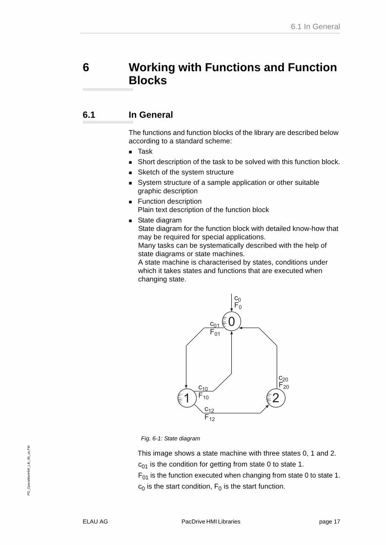
State diagramState diagram for the function block with detailed know-how that may be required for special applications.Many tasks can be systematically described with the help of state diagrams or state machines.A state machine is characterised by states, conditions under which it takes states and functions that are executed when changing state.
Fig. 6-1: State diagram
This image shows a state machine with three states 0, 1 and 2.
c01 is the condition for getting from state 0 to state 1.
F01 is the function executed when changing from state 0 to state 1.
c0 is the start condition, F0 is the start function.
�
� �������
������
������
����
������
ELAU AG PacDrive HMI Libraries page 17

PD
_Ope
raM
anH
MI_
Lib_
06_u
s.F
M
6 Working with Functions and Function Blocks
Kor
rekt
urau
sdru
ck
Machine in state 0:
If the condition c01 is met, the function F01 is executed and the machine changes to state 1. It will remain there until conditions c10 or c12 are fulfilled.
The above state machine can describe e.g. the following motion task:
Start of the machine
c0: start enable
F0: issue ‘ready’
State 0: ready to start
c01: start signal recognised
F01: positioning task
State 1: drive to target position
c12: target change recognised
F12: set new target position
c10: target position reached
F10: issue ‘target position reached’
State 2: drive to changed target position
c20: corrected target reached
F20: issue ‘corrected target reached’
page 18 PacDrive HMI Libraries ELAU AG
PD
_Ope
raM
anH
MI_
Lib_
06_u
s.F
M6.1 In General
Kor
rekt
urau
sdru
ck
CallCalls a function block in FBD (and/or maybe in ST)
Declaration of the interfaceDescribes the input and output parameters of the function blockResult of the function block.
ExamplesSuitable examples to impart the function of a component to the user in a “simple” environment or “stand-alone”.
NOTE
It may happen that a function description contains not all of the points in this scheme.
The function blocks of HMI.Lib have the following basic characteristics:
Cyclic call
The function blocks (FCs) are designed for cyclic applications. A typical cycle time is 5 ms.
General inputs and outputs
The following inputs and outputs are obligatory for all FCs of the HMI.Lib
Input: Enable
The input Enable (BOOL) enables the component and initialises it when it is first called. When leaving, the component is “tidied up“, i.e. all motions are stopped. System functions that were activated are deactivated, global and output variables are set accordingly, etc.
Output Active
The output Active (BOOL) is TRUE if Enable is TRUE and there is no error (Result >= 0 ).
Output Result
The output Result (DINT) normally shows the state of the FC. In case of an error, it shows the corresponding error number. The error numbers are non-equivocal for all FCs and contained in a common list.
ELAU AG PacDrive HMI Libraries page 19

PD
_Ope
raM
anH
MI_
Lib_
06_u
s.F
M
6 Working with Functions and Function Blocks
Kor
rekt
urau
sdru
ck
6.2 Connection to Lauer PCS
6.2.1 In General
The Lauer PCS topline series (micro, mini, midi and maxi) are a group of operating consoles which can be operated always with the same drivers. For communication via serial interface, for example, Lauer offers the drivers simmini.drv and simmidi.drv. A serial driver for PCS topline maxi is not yet available.
Table 6-1: .Lauer PCS series
Series Units
PCS topline micro PCS 009, PCS 009plus
PCS topline mini PCS 090, PCS 090plus, PCS 095, PCS 095plus
PCS topline midi PCS 900, PCS 920, PCS 950 (PCS 950c)
PCS topline maxi PCS 900, PCS 9100
page 20 PacDrive HMI Libraries ELAU AG
PD
_Ope
raM
anH
MI_
Lib_
06_u
s.F
M6.2 Connection to Lauer PCS
Kor
rekt
urau
sdru
ck
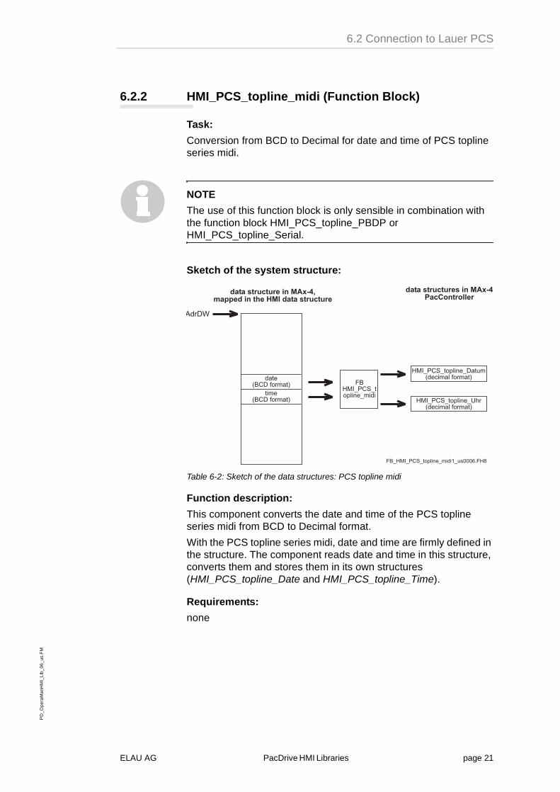
6.2.2 HMI_PCS_topline_midi (Function Block)
Task:
Conversion from BCD to Decimal for date and time of PCS topline series midi.
NOTE
The use of this function block is only sensible in combination with the function block HMI_PCS_topline_PBDP or HMI_PCS_topline_Serial.
Sketch of the system structure:
Table 6-2: Sketch of the data structures: PCS topline midi
Function description:
This component converts the date and time of the PCS topline series midi from BCD to Decimal format.
With the PCS topline series midi, date and time are firmly defined in the structure. The component reads date and time in this structure, converts them and stores them in its own structures (HMI_PCS_topline_Date and HMI_PCS_topline_Time).
Requirements:
none
���
��� �����������
��� �����������
���������������� �����
����������������� ��������������������������������
�������������� ��� ��� �������������
�������������� �!"��� �������������
������������������ ���������������
����������������� ������� #���$%��&
ELAU AG PacDrive HMI Libraries page 21

PD
_Ope
raM
anH
MI_
Lib_
06_u
s.F
M
6 Working with Functions and Function Blocks
Kor
rekt
urau
sdru
ck
Call in FBD:
Declaration of the interface:FUNCTION_BLOCK HMI_PCS_topline_midi
VAR_INPUT
Enable: BOOL; (* enable conversion *)
AdrDW : DWORD;(*address to global structure of datafieldwords*)
END_VAR
VAR_OUTPUT
Date : HMI_PCS_topline_Date;(*local structure of date*)
Time : HMI_PCS_topline_Time;(*local structure of time*)
END_VAR
Structures:
TYPE HMI_PCS_topline_Date :
STRUCT
year : WORD;
day : BYTE;
month : BYTE;
END_STRUCT
END_TYPE
TYPE HMI_PCS_topline_Time :
STRUCT
hour : BYTE;
weekday: BYTE;
second: BYTE;
minute: BYTE;
END_STRUCT
END_TYPE
Result:
no result
Examples:
page 22 PacDrive HMI Libraries ELAU AG

PD
_Ope
raM
anH
MI_
Lib_
06_u
s.F
M6.2 Connection to Lauer PCS
Kor
rekt
urau
sdru
ck
6.2.3 HMI_PCS_topline_PBDP (Function Block)
Task:
Connection of PCS topline operating terminals to the PacDrive Controller via PROFIBUS DP.
Sketch of the system structure:
Table 6-3: Sketch of data structures: PCS topline PBDP
Function description:
This component is used for the communication between the PacDrive Controller and a Lauer PCS topline operating unit (HMI), e.g. PCS 095plus, using the PROFIBUS DP protocol. In principle, the communication happens in such a way that the HMI sends a request to the PacDrive Controller, which upon receipt returns its answer. This means that the activity is always initiated by the HMI. The PacDrive Controller is a slave. Only one slave is possible.
The FC is set ready for communication by means of a positive edge on Enable. A falling edge on Enable terminates the FC’s readiness for communication.
Communication is monitored via the input Timeout. A maximum time (typically in milliseconds) that may lie between two request telegrams is transmitted here. If the time is exceeded, the Result is set accordingly. By default, the Timeout is set to 1000 ms.
The address of the data word range on the PacDrive Controller must be transmitted in AdrDW. This data word range is usually a structure oriented at the corresponding HMI.
The start address of the input range (input address in the basic parameters of the PacDrive Controller PROFIBUS DP module) is transmitted in AdrEB.
The start address of the output range (output address in the basic parameters of the PacDrive Controller PROFIBUS DP module) is transmitted in AdrAB.
��#� ��'(���!�)�
���� ������#�� �� � �������������
���������� *+� �*���#� �
�'(���!�)��)����,
����������� ����-).*+� �*����,
�'(���!�)��)���#� �
��
�����������
��� �
���
�� ��� ��� ������ ��� #���$%��&
�����
���
�
�����/�������0
��� ����0
���12 ���� ������� � ��
� �� ����0
�����
�����
����
�����
�
�����#�� �� � �������������
ELAU AG PacDrive HMI Libraries page 23

PD
_Ope
raM
anH
MI_
Lib_
06_u
s.F
M
6 Working with Functions and Function Blocks
Kor
rekt
urau
sdru
ck
The size of the data word range in bytes (number of marker bytes) is entered in SizeMB. The transmission value is always equivalent to the value SIZEOF (DW). By default, SizeMB is 512, which is equivalent to 256 data words.
The size of the input range is entered in SizeEB.
See also PROFIBUS DP Configurator – Inputs/Outputs –Input Length
NOTE
If direct parameters are used, AdrEB rises by the number of direct parameters and SizeEB decreases by the number of direct parameters. The direct parameters are configured in the HMI. Up to 4 direct parameters can be configured.
The size of the output range is entered in SizeAB.
see also PROFIBUS DP Configurator – Inputs/Outputs –Output Length
The output Active indicates whether a component is being processed error-free at a certain time.
Requirements:
PBDP_M_V000600.lib or higher
page 24 PacDrive HMI Libraries ELAU AG

PD
_Ope
raM
anH
MI_
Lib_
06_u
s.F
M6.2 Connection to Lauer PCS
Kor
rekt
urau
sdru
ck
Call in FBD:
Declaration of the interface:FUNCTION_BLOCK HMI_PCS_topline_PBDP
VAR_INPUT
Enable: BOOL;(* Enable Communication *)
AdrDW: DWORD;(* address of array of datafieldwords *)
AdrEB: DWORD;(* address of array of inputbytes *)
AdrAB: DWORD;(* address of array of outputbytes *)
SizeMB: DINT:= 512;(*size of array of datafieldwords in byte*)
SizeEB: DINT:= 8;(* size of array of inputbytes *)
SizeAB: DINT:= 8;(* size of array of outputbytes *)
Timeout: TIME:= t#1s;
END_VAR
VAR_OUTPUT
Active: BOOL;(* FB active *)
Result: DINT;
END_VAR
Result:
0 -> no error
< 0 -> for error codes refer to DATATYPE eErrorCode in Basic.Lib
Examples:
ELAU AG PacDrive HMI Libraries page 25

PD
_Ope
raM
anH
MI_
Lib_
06_u
s.F
M
6 Working with Functions and Function Blocks
Kor
rekt
urau
sdru
ck
6.2.4 HMI_PCS_topline_Serial (Function Block)
Task:
Connection of PCS topline operating terminals to the PacDrive Controller via the COM 2 serial interface of the PacDrive Controller.
Sketch of the system structure:
Table 6-4: PSketch of data structures: PCS topline serial
Function description:
This component is used for the communication between the PacDrive Controller and a Lauer PCS topline operating unit (HMI), e.g. PCS 095plus, using the serial interface. In principle, the communication happens in such a way that the HMI sends a request to the PacDrive Controller, which upon receipt returns its answer. This means that the activity is always initiated by the HMI. The PacDrive Controller is a slave. Only one slave is possible.
The FC is set ready for communication by means of a positive edge on Enable. A falling edge on Enable terminates the FC’s readiness for communication.
Communication is monitored via the input Timeout. A maximum time (typically in milliseconds) that may lie between two request telegrams is transmitted here. If the time is exceeded, the Result is set accordingly. By default, the Timeout is set to 1000 ms.
The address of the data word range on the PacDrive Controller must be transmitted in AdrDW. This data word range is usually a structure oriented at the corresponding HMI.
The size of the data word range in bytes (number of marker bytes) is entered in SizeMB. The transmission value is always equivalent to the value SIZEOF (DW). By default, SizeMB is 512, which is equivalent to 256 data words.
��#� �
# �������� ����
���� ������#�� �� � �������������
���������� ���#� ��
����������� ����-).����, �
��
�������������� �� �� ��
����������������� �� �� ��� #���$%��&
�����
���
�
�����/�������0
�����#�� �� � �������������
page 26 PacDrive HMI Libraries ELAU AG

PD
_Ope
raM
anH
MI_
Lib_
06_u
s.F
M6.2 Connection to Lauer PCS
Kor
rekt
urau
sdru
ck
The address or ID of the COM object from the control configuration is transmitted in ComIecId.
The output Active indicates whether a component is being processed error-free at a certain time.
Requirements:
none
Call in FBD:
Declaration of the interface:FUNCTION_BLOCK HMI_PCS_topline_Serial
VAR_INPUT
Enable: BOOL;
AdrDW: DWORD;
SizeMB: DINT:= 512;
ComIecId: DINT;(* ComIec Object-Id *)
Timeout: TIME:= t#1s;
END_VAR
VAR_OUTPUT
Active: BOOL;(* FB active *)
Result: DINT;
END_VAR
Result:
≥ 0 -> no error (return values e.g. from ComIecRead)
< 0 -> for error codes refer to DATATYPE eErrorCode in Basic.Lib
ELAU AG PacDrive HMI Libraries page 27

PD
_Ope
raM
anH
MI_
Lib_
06_u
s.F
M
6 Working with Functions and Function Blocks
Kor
rekt
urau
sdru
ck
Examples:
Occupation of the interface cable:
Table 6-5: Occupation of the interface cable for serial connection to PCS topline HMI
���� ������#�� +� ��)�����������
���� ������#�� ��-).��(��
�3 ��
� �����
��-�/����
� �����
��-�/����
�3��
4-)
4-5
'-5
'-)
� � �, ���� ���
� � �, ���� ���
# ���� �� ���
# ���� �� ���
#"� ������#��0�67
��
.
�
�
8
8)����)� 2�#��9 �
:
.
�3)����)� 2�#��9 �
�
3
8
�� +� �;�� #���$%��&
page 28 PacDrive HMI Libraries ELAU AG

PD
_Ope
raM
anH
MI_
Lib_
06_u
s.F
M6.3 Connection to ModBus
Kor
rekt
urau
sdru
ck
6.3 Connection to ModBus
6.3.1 Modbus (Function Block)
Task:
This function block can be used for external units to communicate with the PacDrive Controller via Modbus RTU protocol.
In this case, the PacDrive Controller always operates as the only slave, i.e. the external unit requests the communication, and PacDrive Controller replies to the requests.
Sketch of the system structure:
Communication structure
HMI and PacDrive Controller communicate via the serial interface. There are four data ranges in the IEC program on PacDrive Controller. Two of these ranges can be addressed bitwise, the other two wordwise. To exchange data, the HMI sends a request and a section is transmitted.
Function description:
This component is used for the communication between PacDrive Controller and HMI via the Modbus protocol (e.g. SIMATIC OP?? or ProFace). In principle, the communication happens in such a way that the HMI sends a request to the PacDrive Controller, which upon receipt returns its answer. This means that the activity is always initiated by the HMI. The PacDrive Controller is a slave. Only one slave is possible.
The FC is set ready for communication by means of a positive edge on Enable. A falling edge on Enable terminates the FC’s readiness for communication.
If the input Reset is FALSE, a Result once set is no longer overwritten. If Reset is TRUE, the previous error is deleted and the actual Result is shown.
Communication is monitored via the input Timeout. A maximum time in milliseconds that may lie between two request telegrams is transmitted here. If the time is exceeded, the Result is set accordingly.
Moreover, the FC needs the slave number under which PacDrive Controller is addressed. Make sure that the number is identical with the one projected in the project tool of the visualization surface.
To access the interface, the ComIec object ID must be transmitted.
The corresponding ranges for the variables projected in the visualization tool must be declared in the EPAS-4 programming system as arrays with the required length.
The bit range 1x and the word range 3x are mere read ranges. The bit range 0x and the word range 4x are read/write ranges. This must be taken into account when creating a project.
ELAU AG PacDrive HMI Libraries page 29
PD
_Ope
raM
anH
MI_
Lib_
06_u
s.F
M
6 Working with Functions and Function Blocks
Kor
rekt
urau
sdru
ck
The array sizes can lie between 1 and 9999 (depending on the project).
Declaration example:VAR CONSTANT
s_iSizeofB0000: INT:=3000;
(* define constant for size of array a_bArrB0000 *)
s_iSizeofB1000: INT:=3000;
(* define constant for size of array a_bArrB0000 *)
s_iSizeofW3000:INT:=2500;
(* define constant for size of array a_bArrB0000 *)
s_iSizeofW4000:INT:=2500;
(* define constant for size of array a_bArrB0000 *)
END_VAR
VAR
a_bArrB0000:ARRAY[1..s_iSizeofB0000] OF BOOL:=s_iSizeofB0000(FALSE);
(* define and initialize array for write and read bit values *)
a_bArrB1000:ARRAY[1..s_iSizeofB1000] OF BOOL:=s_iSizeofB1000(FALSE);
(* define and initialize array for read bit values *)
a_bArrW3000:ARRAY[1..s_iSsizeofW3000] OF WORD:=s_iSizeofW3000(0);
(* define and initialize array for read word values *)
a_bArrW4000:ARRAY[1..sizeofW4000] OF WORD:=s_iSizeofW4000(0);
(* define and initialize array for write and read word values *)
mMOD_BUS:Modbus;
END_VAR
As input variables, the FC needs the address of the corresponding array (e.g. ADR(a_bArrB0000)) and its length (e.g. s_iSizeofB000). Please define the lengths using constants, which are then transmitted to the FC, so that there can be no access outside the defined range.
Variables to be transmitted to the HMI must be copied in the PLC program to the corresponding places in the Modbus memory range; received variables must be read from the Modbus memory range.
Alternatively, the array fields can be used directly in the IEC program.
The Modbus process must be called up cyclically. The optimum cycle time depends on the baud rate (maximum 38400 baud), the time between the request telegrams (depending on the external unit) and the relevance of the data to be transmitted (only visualization, writing of variables on the control). The maximum adjustable cycle time basically depends on the timeout of the external unit (how long does it wait for a reply telegram). In most tests, a cycle time of 20 ms was used.
page 30 PacDrive HMI Libraries ELAU AG

PD
_Ope
raM
anH
MI_
Lib_
06_u
s.F
M6.3 Connection to ModBus
Kor
rekt
urau
sdru
ck
Requirements:
Max4_V000700.lib, TSC_V000702.lib, Standard.lib and Basic_V000701.lib
or
Max4_V001000.lib or higher, Standard.lib and Basic_V000701.lib
Call in FBD:
Declaration of the interface:FUNCTION_BLOCK Modbus
VAR_INPUT
Enable: BOOL;(* edge activates/deactivates FC *)
Reset : BOOL;(* input on TRUE resets Result *)
Timeout: UDINT;(* max. time between 2 request telegrams in ms*)
Modbus_SlaveNo: INT;(* slave number within the Modbus system*)
ComIecId: DINT;(* logic address of ComIec object *)
lwAdrB0000: DWORD;(* address of array B0000 *)
sizeofB0000: INT;(* number of elements in array B0000 *)
lwAdrB1000: DWORD;(* address of array B1000 *)
sizeofB1000: INT;(* number of elements in array B1000 *)
lwAdrW3000: DWORD;(* address of array W3000 *)
sizeofW3000: INT;(* number of elements in array W3000 *)
lwAdrW4000: DWORD;(* address of array W4000 *)
sizeofW4000: INT;(* number of elements in array W4000 *)
END_VAR
VAR_OUTPUT
Active: BOOL;(* status indication *)
Result: DINT;(* return value *)
State : (ComMODBUS_UNSYNCHRONIZED,ComMODBUS_SYNCHRONIZED,
ComMODBUS_RECEIVE,ComMODBUS_Send);
(* state of communication *)
END_VAR
Result:
0 -> error-free execution
< 0 -> for error codes refer to DATATYPE eErrorCode in Basic.Lib
ELAU AG PacDrive HMI Libraries page 31
PD
_Ope
raM
anH
MI_
Lib_
06_u
s.F
M
6 Working with Functions and Function Blocks
Kor
rekt
urau
sdru
ck
Examples:
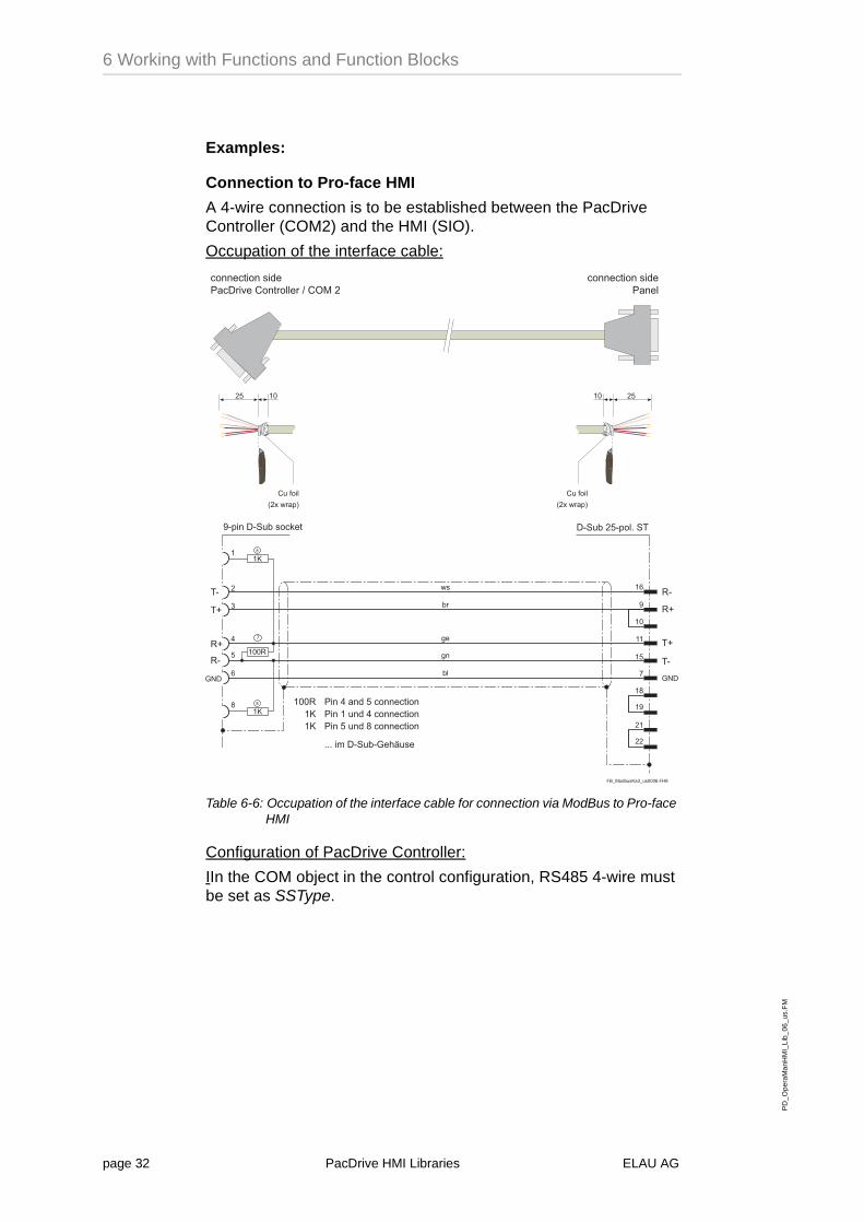
Connection to Pro-face HMI
A 4-wire connection is to be established between the PacDrive Controller (COM2) and the HMI (SIO).
Occupation of the interface cable:
Table 6-6: Occupation of the interface cable for connection via ModBus to Pro-face HMI
Configuration of PacDrive Controller:
IIn the COM object in the control configuration, RS485 4-wire must be set as SSType.
������2 #;�:� #���$%��&
���� ������#�� �����, ��������� ��<��(���
���� ������#�� ��� �
���'�;�;
����.�����3����� ����������� ���.����� ���������3� ���&����� �����
%%%����)� 2)6 "= #
�3 �� �3��
�$
8
��
��
�3
:
.
)� 2��3)���%��4
�
�&
3
�8
��
��
4)
45
'5
')
')
'5
45
4)���'
��;
�;&
$ >67
2�
2�
/#
0
0�
67
>
&
&
� �������-�/����
� �������-�/����
8)����)� 2�#��9 �
page 32 PacDrive HMI Libraries ELAU AG

PD
_Ope
raM
anH
MI_
Lib_
06_u
s.F
M6.3 Connection to ModBus
Kor
rekt
urau
sdru
ck
Program in ST:VAR CONSTANT
s_iSizeofB0000 : INT:=3000;
s_iSizeofB1000 : INT:=3000;
s_iSizeofW3000 : INT:=2500;
s_iSsizeofW4000 : INT:=2500;
END_VAR
VAR
a_bArrB0000 :ARRAY[1..s_iSizeofB0000] OF BOOL :=s_iSizeofB0000(FALSE);
a_bArrB1000 :ARRAY[1..s_iSizeofB1000] OF BOOL :=s_iSizeofB1000(FALSE);
a_bArrW3000 :ARRAY[1..s_iSizeofW3000] OF WORD:=s_iSizeofW3000(0);
a_bArrW4000 :ARRAY[1..s_iSizeofW4000] OF WORD:=s_iSizeofW4000(0);
r_Modbus:Modbus;
END_VAR
(*the data to be transmitted can be copied to the Modbus arrays here*)
r_Modbus(Enable:=TRUE,Reset:=False,Timeout:=2000,Modbus_slaveNr:=1,ComIecId:=_ComIec,
lwAdrB0000:=ADR(a_bArrB0000),sizeofB0000:=s_iSizeofB0000,
lwAdrB1000:=ADR(a_bArrB1000),sizeofB1000:=s_iSizeofB1000,
lwAdrW3000:=ADR(a_bArrW3000),sizeofW3000:=s_iSizeofW3000, lwAdrW4000:=ADR(a_bArrW4000),sizeofW4000:=s_iSizeofW4000);
IF r_modbus.Result<0 THEN
GetResultText(Result:=r_modbus.Result);
(* issue message, if an error occurred *)
ELSE
(*the data transmitted from the Modbus array can be copied here*)
END_IF
ELAU AG PacDrive HMI Libraries page 33

PD
_Ope
raM
anH
MI_
Lib_
06_u
s.F
M
6 Working with Functions and Function Blocks
Kor
rekt
urau
sdru
ck
Connection to Siemens HMI
NOTE
The Modbus connection was tested with an OP 27.You can find further Siemens HMI units with Modbus connection in the Siemens User Manual Communication, Edition 05/99, Chapter 1.2 (manual available on the Internet at:http://www4.ad.siemens.de/infocs/livelink.exe?func=cslib.csinfo&startNode=2401&table=ProductNodes&lang=de&aktprim=0&nodeID0=2401&siteid=cs (last revision: May 2000))
A 4-wire connection is to be established between the PacDrive Controller (COM2) and the HMI (OP 27).
Occupation of the interface cable:
An SA-1 protocol converter is needed to connect the HMI (IF1A).
Cable from HMI (IF1A) to SA-1
Table 6-7: Occupation of the interface cable for connection via ModBus to Siemens HMI (HMI / SA-1)
���� ������#�� ���
���� ������#�� ��)�
� �����
��-�/����
�3���3 ��
� �������-�/����
:
.
�3
3
��
8)����)� 2����� ����
:
3
.
$
>
�3)����)� 2����� ����
&
�
������2 #;��� #���$%��&
page 34 PacDrive HMI Libraries ELAU AG

PD
_Ope
raM
anH
MI_
Lib_
06_u
s.F
M6.3 Connection to ModBus
Kor
rekt
urau
sdru
ck
Cable from SA-1 to PacDrive Controller (Com2)
Table 6-8: Occupation of the interface cable for connection via ModBus to Siemens HMI (SA-1 / PacDrive Controller)
Configuration of the PacDrive Controller:
In the COM object, RS485 4-wire connection must be set.
Configuration of HMI:
Modicon Modbus must be entered as protocol at the interface IF1A.
984 must be entered as PLC.
���� ������#�� ��)�
���� ������#�� ��-).�<��(���
�3 ��
� �������-�/����
� �������-�/����
�3��
.
3
>
�
�.
8)����)� 2�#��9 �
:
.
�3)����)� 2�#��9 �
�
�3
�?5�.?
������2 #;��� #���$%��&
3 $
ELAU AG PacDrive HMI Libraries page 35
PD
_Ope
raM
anH
MI_
Lib_
06_u
s.F
M
6 Working with Functions and Function Blocks
Kor
rekt
urau
sdru
ck
6.4 Connection to Simatic
6.4.1 ComHMI (Function Block)
Task:
Connection of Simatic HMI operating terminal to the PacDrive Controller via the COM 2 serial interface of the PacDrive Controller.
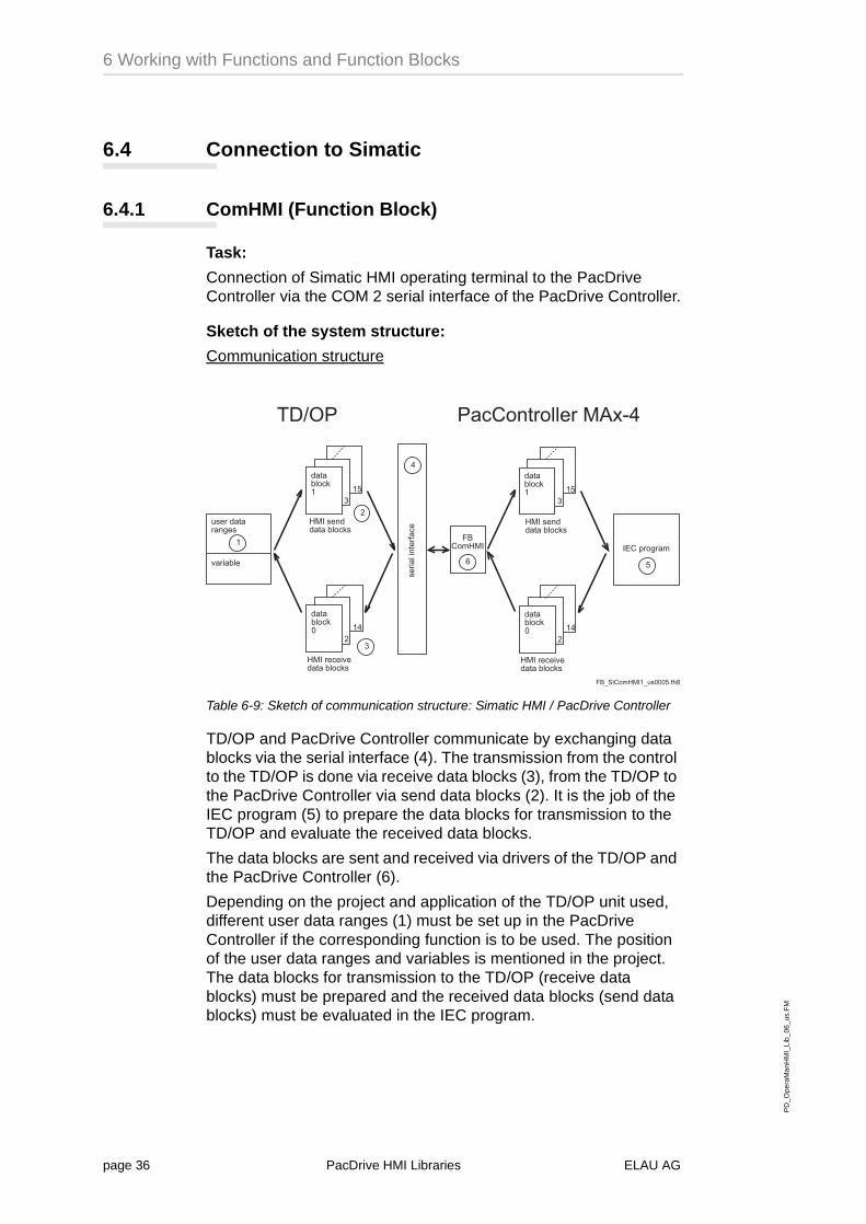
Sketch of the system structure:
Communication structure
Table 6-9: Sketch of communication structure: Simatic HMI / PacDrive Controller
TD/OP and PacDrive Controller communicate by exchanging data blocks via the serial interface (4). The transmission from the control to the TD/OP is done via receive data blocks (3), from the TD/OP to the PacDrive Controller via send data blocks (2). It is the job of the IEC program (5) to prepare the data blocks for transmission to the TD/OP and evaluate the received data blocks.
The data blocks are sent and received via drivers of the TD/OP and the PacDrive Controller (6).
Depending on the project and application of the TD/OP unit used, different user data ranges (1) must be set up in the PacDrive Controller if the corresponding function is to be used. The position of the user data ranges and variables is mentioned in the project. The data blocks for transmission to the TD/OP (receive data blocks) must be prepared and the received data blocks (send data blocks) must be evaluated in the IEC program.
# ���������0 #
,����2�
����2���9�
# �������� ����
:�3
����# �������2���9#
����2���9�
��.
����� � �, �����2���9#
�
�
:
.
�@�����0���
����2���9�
:�3
����# �������2���9#
����2���9�
��.
����� � �, �����2���9#
3
4<(� ����������� ����-).
��������
$
������������� #���3%�"&
page 36 PacDrive HMI Libraries ELAU AG
PD
_Ope
raM
anH
MI_
Lib_
06_u
s.F
M6.4 Connection to Simatic
Kor
rekt
urau
sdru
ck
Function description:
This component is used for the communication between PacDrive Controller and an HMI (SIMATIC TP??/OP??) via the COM2 port. In principle, the communication happens in such a way that the HMI sends a block to the PacDrive Controller, which upon receipt returns a block. This means that the activity is always initiated by the HMI.
The FC is set ready for communication by means of a positive edge on Enable. While the FC is ready for communication, the parameters NoOfBlocks, AdrOfBlocks and ComIecId must not be changed. A falling edge on Enable terminates the FC’s readiness for communication.
The transmitted ComIec object must be added to the control configuration and be already open („IecOpen( _ComIecId );“).
NoOfBlocks specifies the number of blocks for which memory space is reserved at the address AdrOfBlocks. So AdrOfBlocks must point to an ARRAY [0..NoOfBlocks-1] OF DATABLOCK. NoOfBlocks is always an even number, because a send block i-1 (even number) must be defined for every receive block i (odd number). For every block, the length must be given according to the HMI configuration via ProTools (e.g. Block[i].Length:=30, if block i is 30 words long. In this case the greatest available variable block is Variable Block[i].Data[29]). The numbering of the words under ProTool is identical with the index of the Data array in Datatype DataBlock, i.e.: Block 1 word 20 in ProTool is equivalent to Block[1].Data[20] in EPAS-4.
If the data blocks 0 or 1 are not used, you need to enter the following lengths:
Length block 0: 9
Length block 1: 19
If the input Reset is low, an error once set is no longer reset until the input changes to high. Then all previous errors are cancelled and only the errors caused just now are shown in Result.
If the input LifeControl is high, the life bit monitoring is activated.
The error threshold for the life bit monitoring is set with the input LifeTime. Depending on the HMI unit, it may be necessary to increase the error threshold.
A rising edge on the input Reboot causes the HMI to reboot. The high signal on Reboot must not be lifted until the completion of the reboot process is signalled by a rising edge on RebootDone.
A rising edge on the input GiveOrder triggers the control order specified with Order, Parameter1, Parameter2 and Parameter3. None of these five parameters may be changed until the completion of the order is indicated by a rising edge on OrderDone.
The possible orders that can be transmitted with the parameter Order and the meaning of the corresponding parameters are described in the manual ’SIMATIC HMI Communication User
ELAU AG PacDrive HMI Libraries page 37

PD
_Ope
raM
anH
MI_
Lib_
06_u
s.F
M
6 Working with Functions and Function Blocks
Kor
rekt
urau
sdru
ck
Manual‘, Siemens order number: 6AV3991-1BC06-0AA0 Appendix B Control Orders.
If order number 41 was given (transmit date and time from HMI to PacDrive Controller), the complete transmission of the time is indicated by a rising edge on TimeReceived and the complete receipt of the date by a rising edge on DateReceived. The received data are then available in Hour, Minute, Second, respectively in Weekday, Day, Month, Year.
If the HMI triggered an alarm, a rising edge is issued on AlarmReceived and the corresponding flag is set in Alarm01_16, Alarm17_32 or Alarm33_48.
A rising edge on DataReceived signals the receipt of the transmission initiated by control order 70. The requested receipt is then available in the data tray.
Communications supplies the number of data blocks transmitted successfully since the last activation of the component; Errors supplies the number of failed transmissions. Communication does not run safely unless several successfully transmitted data blocks are shown at the output Communications. The reason is that an incomplete protocol, the structure of which complies with the protocol requirements, may be received when booting.
The ComHMI process must be called up cyclically every 200 ms or more often.
State diagram:
Table 6-10: State diagram ComHMI
ComHMI_SYNCHRONIZED
ComHMI_UNSYNCHRONIZED
ComHMI_RECEIVE
COMHMI_SEND
c: valid block
c: whole blockreceived
c: sendigsuccesful
c: validsynchronisation
c: error
c: error
c: error
page 38 PacDrive HMI Libraries ELAU AG
PD
_Ope
raM
anH
MI_
Lib_
06_u
s.F
M6.4 Connection to Simatic
Kor
rekt
urau
sdru
ck
Requirements:
Standard.lib
MAx4_v000600.lib or higher
Basic_V000600.lib or higher
PLC_V000600.lib or higher
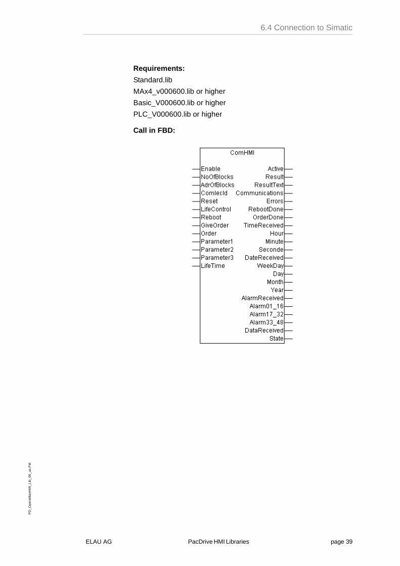
Call in FBD:
ELAU AG PacDrive HMI Libraries page 39
PD
_Ope
raM
anH
MI_
Lib_
06_u
s.F
M
6 Working with Functions and Function Blocks
Kor
rekt
urau
sdru
ck
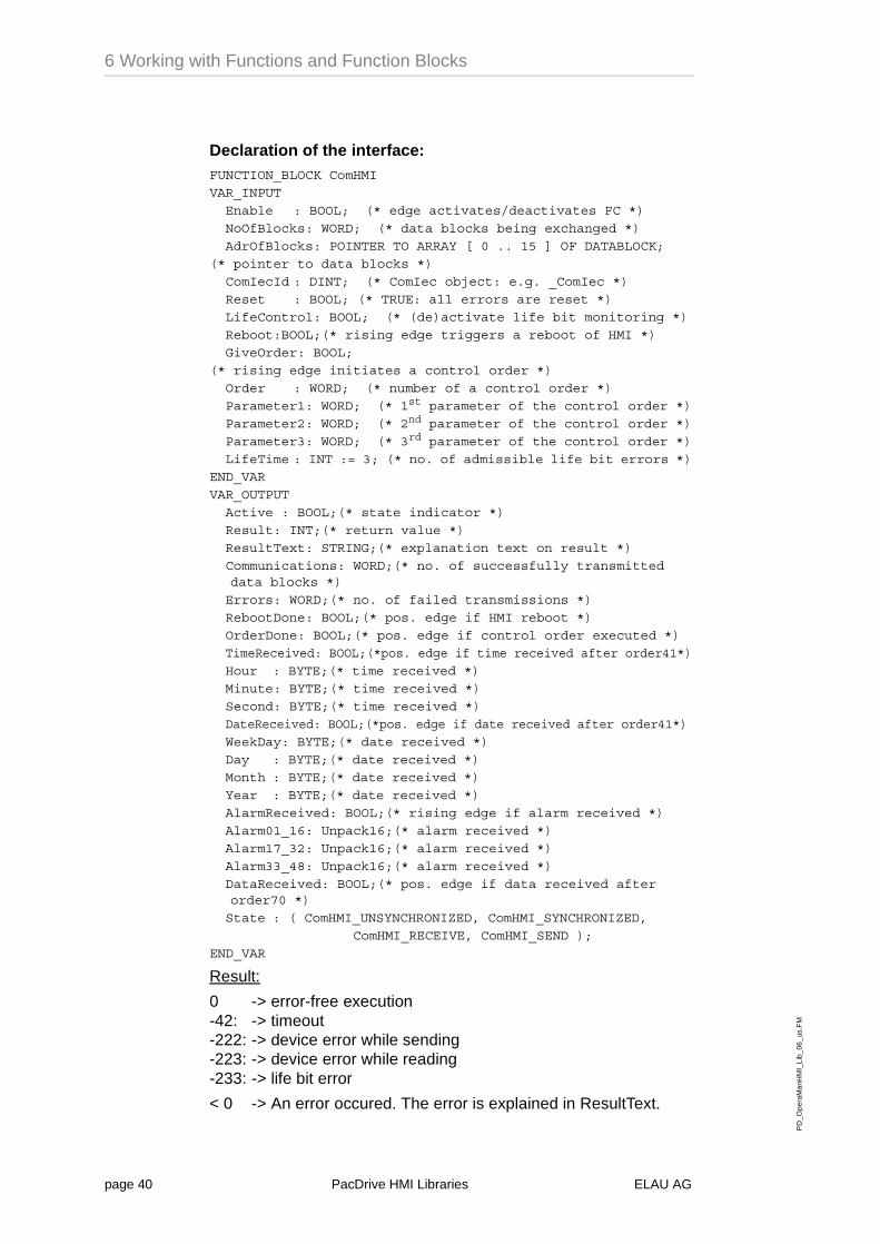
Declaration of the interface:FUNCTION_BLOCK ComHMI
VAR_INPUT
Enable : BOOL; (* edge activates/deactivates FC *)
NoOfBlocks: WORD; (* data blocks being exchanged *)
AdrOfBlocks: POINTER TO ARRAY [ 0 .. 15 ] OF DATABLOCK;
(* pointer to data blocks *)
ComIecId : DINT; (* ComIec object: e.g. _ComIec *)
Reset : BOOL; (* TRUE: all errors are reset *)
LifeControl: BOOL; (* (de)activate life bit monitoring *)
Reboot:BOOL;(* rising edge triggers a reboot of HMI *)
GiveOrder: BOOL;
(* rising edge initiates a control order *)
Order : WORD; (* number of a control order *)
Parameter1: WORD; (* 1st parameter of the control order *)
Parameter2: WORD; (* 2nd parameter of the control order *)
Parameter3: WORD; (* 3rd parameter of the control order *)
LifeTime : INT := 3; (* no. of admissible life bit errors *)
END_VAR
VAR_OUTPUT
Active : BOOL;(* state indicator *)
Result: INT;(* return value *)
ResultText: STRING;(* explanation text on result *)
Communications: WORD;(* no. of successfully transmitted data blocks *)
Errors: WORD;(* no. of failed transmissions *)
RebootDone: BOOL;(* pos. edge if HMI reboot *)
OrderDone: BOOL;(* pos. edge if control order executed *)
TimeReceived: BOOL;(*pos. edge if time received after order41*)
Hour : BYTE;(* time received *)
Minute: BYTE;(* time received *)
Second: BYTE;(* time received *)
DateReceived: BOOL;(*pos. edge if date received after order41*)
WeekDay: BYTE;(* date received *)
Day : BYTE;(* date received *)
Month : BYTE;(* date received *)
Year : BYTE;(* date received *)
AlarmReceived: BOOL;(* rising edge if alarm received *)
Alarm01_16: Unpack16;(* alarm received *)
Alarm17_32: Unpack16;(* alarm received *)
Alarm33_48: Unpack16;(* alarm received *)
DataReceived: BOOL;(* pos. edge if data received after order70 *)
State : ( ComHMI_UNSYNCHRONIZED, ComHMI_SYNCHRONIZED,
ComHMI_RECEIVE, ComHMI_SEND );
END_VAR
Result:
0 -> error-free execution-42: -> timeout-222: -> device error while sending-223: -> device error while reading-233: -> life bit error
< 0 -> An error occured. The error is explained in ResultText.
page 40 PacDrive HMI Libraries ELAU AG
PD
_Ope
raM
anH
MI_
Lib_
06_u
s.F
M6.4 Connection to Simatic
Kor
rekt
urau
sdru
ck
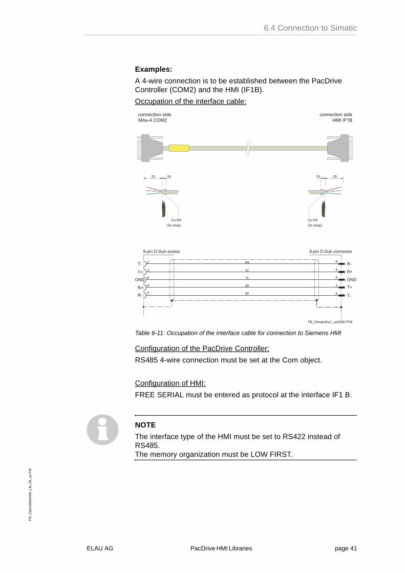
Examples:
A 4-wire connection is to be established between the PacDrive Controller (COM2) and the HMI (IF1B).
Occupation of the interface cable:
Table 6-11: Occupation of the interface cable for connection to Siemens HMI
Configuration of the PacDrive Controller:
RS485 4-wire connection must be set at the Com object.
Configuration of HMI:
FREE SERIAL must be entered as protocol at the interface IF1 B.
NOTE
The interface type of the HMI must be set to RS422 instead of RS485.The memory organization must be LOW FIRST.
���� ������#�� ��������
���� ������#�� ��-).��(��
�3 ��
� �������-�/����
� �������-�/����
�3��
8
.
3
:
&
8)����)� 2�#��9 �
:
.
8)����)� 2����� ����
�
3
4)
45
'5
')
')
'5
45
4)
/#
2�
0
0�
67$67 �#
����������;��� #���$%��&
ELAU AG PacDrive HMI Libraries page 41
PD
_Ope
raM
anH
MI_
Lib_
06_u
s.F
M
6 Working with Functions and Function Blocks
Kor
rekt
urau
sdru
ck
Program in ST:VAR
Block : ARRAY [ 0 .. 1 ] OF HMI_SIM_DATABLOCK;
aComHMI: ComHMI;
Init : BOOL := TRUE;
Old : BOOL;
END_VAR
IF Init THEN
Init := FALSE;
ComIecOpen( _ComIec );
Block[0].Length := 50;
Block[1].Length := 50;
aComHMI.NoOfBlocks := 2;
aComHMI.AdrOfBlocks := ADR( Block );
aComHMI.ComIecId := _ComIec;
END_IF
aComHMI.LifeControl := TRUE;
aComHMI.Reset := FALSE;
Block[0].Data[19] := 1;(* values 1, 2 and 3 will soon *)
Block[0].Data[20] := 2;(* be sent to the HIM via words *)
Block[0].Data[21] := 3; (* 19, 20 and 21 in block 0 *)
(* reboot HMI *)
(* rising edge on Reboot starts boot procedure *)
(* rising edge on RebootDone signals end of boot procedure *)
aComHMI( Enable := TRUE, Reboot := FALSE );
REPEAT
Old := aComHMI.RebootDone;
aComHMI( Enable := TRUE, Reboot := TRUE );
UNTIL aComHMI.RebootDone AND NOT Old END_REPEAT;
(* Receipt with ID number 100 received by HMI by means of control order in data cache e.g. Block[1].Data[20] to Block[1].Data[30], depending on the configuration with ProTools. The receipt 100 and a data tray must be defined with ProTools on the HMI. Rising edge on GiveOrder gives the control order. Rising edge on DataReceived confirms receipt of requested data. The execution of the control order may have been done prematurely by rising edge on OrderDone, irrespective of the receipt of data *)
aComHMI( Enable:=TRUE, GiveOrder:=FALSE );
REPEAT
Old := aComHMI.DataReceived;
aComHMI(Enable:=TRUE, Order:=70, Parameter1:=1, Parameter2:=0, Parameter3:=0, GiveOrder:=TRUE );
UNTIL aComHMI.DataReceived AND NOT Old END_REPEAT;
Note: The REPEAT-UNTIL loops are meant for demonstration purposes only and should be realized by cyclic calls in the actual application.
page 42 PacDrive HMI Libraries ELAU AG

PD
_Ope
raM
anH
MI_
Lib_
06_u
s.F
M6.4 Connection to Simatic
Kor
rekt
urau
sdru
ck
NOTE
Notes for project creation in ProTool:
Calculation of block lengths:
In principle, the following applies: The variables of two consecutive blocks 2*i and 2*i+1 for i>=0 occupy the same memory space. E.g. Block[4].Word[3]=Block[5].Word[3]. The blocks 0 and 1 inevitably are an exception, as in block 1 words are only available from 19, whereas in block 0 words are already available from word 9.
Consequently, the block lengths for the blocks 2*i and 2*i+1 result from the highest word used in one of the blocks. Example: If the highest word used in Block 0 is word 23 and the highest word used in block 1 is word 20, the common block length is 24.
There are exceptions if range pointers are used. Range pointers enlarge the block length if the range they define exceeds the highest defined words. However, as some range pointers are defined only for the receive block or only for the send block, they only affect the length of one of these blocks, not both of them at the same time.
Solution: To recognize a common block length reliably, you should define a variable that lies beyond all defined ranges and thus defines the absolute block length.
Variables that are not used must not be taken into account when calculating the block length, as these are not sent/received.
Setting of block priorities:
1) The priority must be set to 0. With any other setting, the HMI will no longer send the block.
Variable configuration:
If the field ‘read always’ is selected for the variables, the block is transmitted or requested with the configured poll time.
When a block is transmitted for the first time, all data are transmitted. For all following transmissions, the block is transmitted only up the variable that changed since the last transmission.
If the field ‘read always’ is not selected, the variables can only be updated by means of a receipt. A command must be given to update a receipt.
ELAU AG PacDrive HMI Libraries page 43

PD
_Ope
raM
anH
MI_
Lib_
06_u
s.F
M
6 Working with Functions and Function Blocks
Kor
rekt
urau
sdru
ck
page 44 PacDrive HMI Libraries ELAU AG
PD
M_A
nhan
gStd
_us.
FM
7.1 Contact
Kor
rekt
urau
sdru
ck
7 Appendix
7.1 Contact
For repair
Please send the components to be repaired or checked, along with the error report, to this address:
ELAU AGAbt. Kundendienst house address:Postfach 1255 Dillberg 1297821 Marktheidenfeld 97828 MarktheidenfeldPhone: +49 (0) 93 91 / 606-142Fax: +49 (0) 93 91 / 606-340
Service team
Should you need to talk to a member of our service team or require on-site service, please contact:
ELAU AGDillberg 12D-97828 MarktheidenfeldPhone: +49 (0) 9391 / 606 - 0Fax: +49 (0) 9391 / 606 - 300e-mail: [email protected]: www.elau.de
ELAU, Inc.165 E. Commerce DriveSchaumburg, IL 60173 - USAPhone: +1 847 490 4270Fax: +1 847 490 4206e-mail: [email protected]: www.elau.com
ELAU SYSTEMS ITALIA S.r.l.Via Tosarelli 300I-40050 Villanova di Castenaso (BO)Phone: +39 051 / 7818 70Fax: +39 051 / 7818 69e-mail: [email protected]: www.elau.it
NOTF
You can find further contact addresses on the ELAU homepage (www.elau.de).
ELAU AG PacDrive page 45

PD
M_A
nhan
gStd
_us.
FM
7 Appendix
Kor
rekt
urau
sdru
ck
7.2 Further Literature
ELAU can provide you with these manuals and instructions on the PacDrive™ System:1
Project Manual
Art.No. 17 13 00 58 - 00x (DE, EN, FR)
Programming Manual
Art.No. 17 13 00 61 - 00x (DE, EN)
Operating Manual MC-4 Servo Drive
Art.No. 17 13 00 62 - 00x (DE, EN, IT, FR)
Operating Manual CAN L2
Art.No. 17 13 00 66 - 00x (DE, EN)
Operating Manual PROFIBUS-DP
Art.No. 17 13 00 67 - 00x (DE, EN)
Operating Manual SM Motor
Art.No. 17 13 00 68 - 00x (DE, EN, IT, FR)
Operating Manual EPAS-4
Art.No. 17 13 00 70 - 00x (DE, EN)
Operating Manual PacDrive Controller MAx-4
Art.No. 17 13 00 71 - 00x (DE, EN, IT, FR)
Operating Manual OPC-Server
Art.No. 17 13 00 73 - 00x (DE, EN)
Operating Manual Device Net
Art.No. 17 13 00 76 - 00x (DE, EN)
Operating Manual HMI Libraries
Art.No. 17 13 00 77 - 00x (DE, EN)
Operating Manual INC-4 Incremental Encoder Module
Art.No. 17 13 00 78 - 00x (DE, EN)
Operating Manual CANopen
Art.No. 17 13 00 79 - 00x (DE, EN)
Operating Manual VarioCam® Editor ECAM-4
Art.No. 17 13 00 80 - 00x (DE, EN)
Operating Manual PacNet Module PN-4
Art.No. 17 13 00 81 - 00x (DE, EN)
Operating Manual SR Motor
Art.No. 17 13 00 82 - 00x (DE, EN)
1. Art.No. -000 (DE) german -001 (EN) english -002 (IT) italian -003 (FR) french
page 46 PacDrive ELAU AG
PD
M_A
nhan
gStd
_us.
FM
7.2 Further Literature
Kor
rekt
urau
sdru
ck
Operating Manual BusTerminal BT-4/DIO1
Art.No. 17 13 00 83 - 00x (DE, EN)
Operating Manual TTS
Art.No. 17 13 00 88 - 00x (DE)
User Manual Automatic Controller Optimization
Art.No. 17 13 00 89 - 00x (DE, EN)
Operating Manual PacDrive SCL
Art.No. 17 13 00 93 - 00x (DE, EN)
Operating Manual PacDrive PS-4 und PacDrive PD-8
Art.No. 17 13 00 94 - 00x (DE, EN)
Operating Manual Evaluation Kit
Art.No. 17 13 00 95 - 00x (DE)
Operating Manual PacDrive Controller P600
Art.No. 17 13 00 96 - 00x (DE, EN)
Operating Manual PacDrive Controller C200
Art.No. 17 13 00 97 - 00x (DE, EN, FR)
Operating Manual PacDrive Controller C400
Art.No. 17 13 00 98 - 00x (DE, EN, FR)
Operating Manual PacDrive Controller C600
Art.No. 17 13 00 99 - 00x (DE, EN, FR)
ELAU AG PacDrive page 47

hang
Std
_us.
FM
7 Appendix
Kor
rekt
urau
sdru
ck
7.3 Product Training
We offer practical workshops and seminars.
Our experienced seminar leaders will enable you to make optimum use of the vast possibilities of the PacDrive™ system.
NOTE
Please contact us for further information or to order our seminar program. See also our homepage (www.elau.de).
PD
M_A
n
page 48 PacDrive ELAU AG
PD
_OpM
anH
MI_
Lib_
Aen
_us
.FM
7.4 Modifications
Kor
rekt
urau
sdru
ck
7.4 Modifications
07 / 2000
Operating Manual newly written
09 / 2004
Update Chapter Connection to ModBus
Update to new Layout
NOTE
The latest documentation and modification service on this product are available on the ELAU Homepage (www.elau.de).
ELAU AG PacDrive HMI Libraries page 49

anH
MI_
Lib_
Aen
_us
.FM
7.4 Modifications
Kor
rekt
urau
sdru
ck
PD
_OpM
page 50 PacDrive HMI Libraries ELAU AG
PD
_Ope
raM
anH
MI_
Lib_
usS
IX.f
m
IndexK
orre
ktur
ausd
ruck
7.5 Index
Ccontact 45
EELAU AG 2eMail
ELAU AG 2
Ffunction block
ComHMI 36HMI_PCS_topline_midi 21HMI_PCS_topline_PBDP
23HMI_PCS_topline_Serial
26ModBus 29
Hhomepage
ELAU AG 2
Iinternet
ELAU AG 2
LLauer PCS 20literature 46
Mmanuals 46
Ooperating manual 46
PProgramming Manual 46
Rrepair 45risk
classification 8
Ssafety
notes 8seminare 48service
-personnel 45symbols, signs 6
Ttrademarks 2training 48
Wwarning notes 8
ELAU AG PacDrive HMI Libraries page 51

raM
anH
MI_
Lib_
usS
IX.f
m
Index
Kor
rekt
urau
sdru
ck
PD
_Ope
page 52 PacDrive HMI Libraries ELAU AG

ELA
U_F
oS
toer
ung_
us.
FM
7.6 Form for Error Report
Kor
rekt
urau
sdru
ck
7.6 Form for Error Report
This error report is absoluteley necessary in order to enable efficient processing.
Send the error report to your ELAU representative or to:
ELAU AG, Abt. KundendienstDillberg 12, D-97828 MarktheidenfeldFax: +49 (0) 93 91 / 606 - 340
Sender:
Details of the defective product
Product name: ..................................................................................
Article number: .................................................................................
Serial number: ..................................................................................
Software version: ..............................................................................
Hardware code: ................................................................................
Parameter enclosed: yes [ ] no [ ]
IEC program enclosed: yes [ ] no [ ]
Details of the machine on which the problem occurred:
Machine producer: ...........................................................................
Type: ................................................................................................
Hours of operation: ...........................................................................
Machine number: ..............................................................................
Date of commissioning: ....................................................................
Producer/Type of machine control:
.........................................................................................................
Company: City: Date:
Department: Name: Phone:
ELAU AG PacDrive error report page 1

oS
toer
ung_
us.
FM
7.6 Form for Error Report
Kor
rekt
urau
sdru
ck
Description of the problem:
..........................................................................................................
..........................................................................................................
..........................................................................................................
Additional information:
Does the switching cabinet have an air conditioning system?Y/N [ ]
Have similar problems occurred before on the same axis?How often: ..............................
Did the problems occur on certain days or times of day?
..........................................................................................................
further information: ..........................................................................................................
..........................................................................................................
..........................................................................................................
..........................................................................................................
..........................................................................................................
..........................................................................................................
..........................................................................................................
..........................................................................................................
..........................................................................................................
..........................................................................................................
..........................................................................................................
..........................................................................................................
..........................................................................................................
Problem state: Causes: Concomitant phenomena:
[ ] persistent [ ] unknown [ ] mechanical problems
[ ] when commissioning [ ] wiring error [ ] failure of mains supply (24V)
[ ] occurs sporadically [ ] mechanical damage [ ] failure of PMC-2
[ ] occurs after about.....hours [ ] moisture inside the unit [ ] motor failure
[ ] occurs in case of shocks [ ] encoder defective [ ] broken cable
[ ] depends on temperature [ ] insufficient ventilation
[ ] foreign object inside unit
ELA
U_F
error report page 2 PacDrive ELAU AG