
KONTROL49 Owner's Manual - Korgi.korg.com/uploads/Support/KONTROL49_Manual... · Keep this manual...
72
2 Owner’s manual E
Transcript of KONTROL49 Owner's Manual - Korgi.korg.com/uploads/Support/KONTROL49_Manual... · Keep this manual...

2
Owner’s manual
E

ii
Precautions
Location
Using the unit in the following locations can result in a malfunction.• In direct sunlight• Locations of extreme temperature or humidity• Excessively dusty or dirty locations• Locations of excessive vibration• Close to magnetic fields
Power supply
Please connect the designated AC adapter to an AC outlet of the correct volt-age. Do not connect it to an AC outlet of voltage other than that for which your unit is intended.
Interference with other electrical devices
Radios and televisions placed nearby may experience reception interference. Operate this unit at a suitable distance from radios and televisions.
Handling
To avoid breakage, do not apply excessive force to the switches or controls.
Care
If the exterior becomes dirty, wipe it with a clean, dry cloth. Do not use liquid cleaners such as benzene or thinner, or cleaning compounds or flammable polishes.
Keep this manual
After reading this manual, please keep it for later reference.
Keeping foreign matter out of your equipment
Never set any container with liquid in it near this equipment. If liquid gets into the equipment, it could cause a breakdown, fire, or electrical shock.Be careful not to let metal objects get into the equipment. If something does slip into the equipment, unplug the AC adapter from the wall outlet. Then con-tact your nearest Korg dealer or the store where the equipment was pur-chased.
THE FCC REGULATION WARNING (for U.S.A.)
This equipment has been tested and found to comply with the limits for a Class B digital device, pursuant to Part 15 of the FCC Rules. These limits are designed to provide reasonable protection against harmful interference in a residential installation. This equipment generates, uses, and can radiate radio frequency energy and, if not installed and used in accordance with the instruc-tions, may cause harmful interference to radio communications. However, there is no guarantee that interference will not occur in a particular installation. If this equipment does cause harmful interference to radio or television recep-tion, which can be determined by turning the equipment off and on, the user is encouraged to try to correct the interference by one or more of the following measures:• Reorient or relocate the receiving antenna.• Increase the separation between the equipment and receiver.• Connect the equipment into an outlet on a circuit different from that to which
the receiver is connected.• Consult the dealer or an experienced radio/TV technician for help.
Unauthorized changes or modification to this system can void the user’s authority to operate this equipment.
CE mark for European Harmonized Standards
CE mark which is attached to our company’s products of AC mains operated apparatus until December 31, 1996 means it conforms to EMC Directive (89/336/EEC) and CE mark Directive (93/68/EEC). And, CE mark which is attached after January 1, 1997 means it conforms to EMC Directive (89/336/EEC), CE mark Directive (93/68/EEC) and Low Voltage Directive (73/23/EEC).Also, CE mark which is attached to our company’s products of Battery oper-ated apparatus means it conforms to EMC Directive (89/336/EEC) and CE mark Directive (93/68/EEC).

iii
Inadvertent operations or unexpected malfunctions may cause the contents of memory to be lost. To safeguard your important data, please save it on your computer. Korg will accept no responsibility for any damages resulting from loss of data.
You must read the separate “Software license agreement” before you install the software for this product. Installing this software will be considered as your acceptance of this agreement.
* Apple, Macintosh and Mac OS are registered trademarks of Apple Computer, Inc.
* The “Built for Mac OS X” graphic trademarks of Apple Computer, Inc., used under license.
* Windows XP is a registered trademark of Microsoft Corporation in the U.S. and other countries.
* All other product and company names are trademarks or registered trademarks of their respective holders.
* All specifications are subject to change without notice. All rights reserved.
Encoders and keys [ ]
Encoders and keys on the KONTROL49’s panel are enclosed in square brackets [ ].
Parameters “ ”
Parameters are enclosed in double quotation marks “ ”.
and symbols
These symbols respectively indicate a point of caution and a note of advice.
About the example displays
Parameter values etc. in the sample displays printed in this manual are only examples; they will not necessarily match the displays on your KONTROL49.
About your data
About the software license agreement
Conventions in this manual

Table of Contents
iv
.............................................................. 9
the power............................................................ 9
scene .................................................................. 9
troller assignments .............................................. 9
ene ................................................................... 11
scene sets on your computer ............................... 12
............................................................ 13
trollers ............................................................... 13
rs and sliders...............................................................13 pads.............................................................................14joystick .........................................................................15nd, Mod Wheel..........................................................15s 1 and 2 ......................................................................16EDAL jack/SWITCH jack) ......................................16
uick Start....1. Turning on
2. Selecting a
3. Making con
4. Saving a sc
5. Managing
ay mode.....Using the con
1. Encode2. Trigger3. Vector 4. Pitch Be5. Switche6. Pedal (P
7. Main encoder ...........................................................................178. Keyboard ..................................................................................18ting mode............................................................. 19Scene parameter settings ........................................................ 19
Global parameter settings ....................................................... 19
About the OCTAVE SHIFT/CURSOR keys, [ENTER] key, and [EXIT] key ........................................................................................ 19
[1] ENCODER (Encoder assignment) ......................................... 20■ Assigning NRPN or RPN.......................................................21Inputting a name.........................................................................22
Table of Contents
Contents of the package ..............................................vi
Introduction........................................................1
Main features.............................................................. 1
Parts and what they do ............................................... 2Front panel ............................................................................... 2
About the trigger pad functions .................................................4
Rear panel................................................................................ 5
Making connections and turning the power on ............. 6MIDI & AC adapter connection .................................................. 6
USB connection......................................................................... 6
Operation ..........................................................8
About the KONTROL49’s modes .................................. 81. Play mode ............................................................................ 8
2. Setting mode ........................................................................ 8
3. Message mode ..................................................................... 8
4. Scene mode.......................................................................... 8
Q
Pl
Set

Table of Contents
v
PORT (USB-MIDI Port setting)..............................44
KONTROL49 and the driver ports ........................ 45 devices ...................................................................... 46T devices .................................................................. 46
KONTROL49’s MIDI connectors ........................... 46t connected via USB ................................................ 46nnected via USB....................................................... 46
Global setting) ...................................................46
larity setting ............................................................. 47
alibration setting ....................................................... 47
cklight setting ............................................................ 48
mination setting ........................................................ 48
..........................................................49
ic message).......................................................49
pshot message) ..................................................50
(All Note Off message) .......................................50
M On message)..................................................50
message) ..........................................................50
t message) ........................................................51
(Continue message)...........................................51
mpo message) ...................................................51
MESG 1–8 (User message)..................................51
...........................................................52
AVE SHIFT/CURSOR keys, [ENTER] key, and [EXIT] .........................................................................52
Scene ...............................................................52
nel ...................................................................53
.........................................................................53
Quick-assign for control changes ............................................. 23
[2] SLIDER (Slider assignment) ..................................................24
[3] PAD 1–8 (PAD 1–8 assignment) ..........................................24
[4] PAD 9–16 (PAD 9–16 assignment) ......................................26
[5] Pitch Bend (Pitch Bend assignment)......................................26Assigning a single MIDI message to the full range (up/down)................................................................................... 26Assigning separate MIDI messages to the up/down ranges ........................................................................................... 28
■ Assigning aftertouch .......................................................... 29■ Assigning velocity .............................................................. 29■ Assigning a control change ............................................... 30
[6] MOD (MOD Wheel assignment) ..........................................30
[7] VECTOR-X (Vector-X assignment) ........................................31
[8] VECTOR-Y (Vector-Y assignment).........................................32
[9] SW1/SW2 (SW1/SW2 assignment) ....................................32Using the switches in one-parameter mode ........................... 32Using the switches in two-parameter mode........................... 33
[10] PEDAL (Pedal assignment) .................................................35■ Assigning a control change................................................... 36
[11] FOOT SW (Foot SW assignment) .......................................36■ Assigning a control change................................................... 37
[12] KEYBOARD (Keyboard setting) ..........................................38
[13] MAIN ENC (Main Encoder assignment) ..............................40■ Assigning Program Change and Bank Select ..................... 40
[14] MESSAGE (Message setting)..............................................41■ CtrlChg (Control Change message)..................................... 42■ ProgChg (Program Change message) ................................. 42■ BankSel (Bank Select message) ............................................. 43■ Free Mesg (Free message) ..................................................... 43
[15] USB-MIDIAbout the
MIDI INMIDI OU
About the When noWhen co
[16] GLOBAL (■ Pedal Po■ Pedal C■ LCD Ba■ Pad Illu
Message mode[1] PANIC (Pan
[2] SNAP (Sna
[3] NOTE OFF
[4] GM ON (G
[5] STOP (Stop
[6] START (Star
[7] CONTINUE
[8] TAP (Tap te
[9]–[16] USER
Scene mode....About the OCTkey ................
[1]–[12] Select
[13] MIDI Chan
[14] DUMP .....

Table of Contents
v
package
ith the following items.ge, make sure that all of these items are present. If ase contact your Korg distributor.
ain unit)
KONTROL49. Use the AC adaptor if you will be module etc. to the KONTROL49 via MIDI. (
☞
p.6 turning the power on”)
NTROL49 to your computer. (
☞
p.6 “Making con-ower on”)
nstallation in your computer (Windows XP only),
back the CD-ROM on audio CD player. Doing so to your hearing as well as to your CD player/
heet/labels
name sheet to indicate the MIDI messages or con- each of the KONTROL49’s trigger pads, and gger pad section. This is a convenient way to d to each of the sixteen trigger pads.
IDI Implementation chart
reement
i
[15] PRELOAD......................................................................... 54
[16] WRITE ............................................................................. 55
Appendices ......................................................56
Available MIDI messages........................................... 56Channel messages .................................................................. 56
System Realtime messages ...................................................... 56
MIDI Control Change messages ............................................... 56
Channel Mode messages......................................................... 57
RPN MSB/LSB......................................................................... 57
Note no.................................................................................. 57
Preset Scene Name.................................................... 58
MIDI implementation ................................................. 58System exclusive messages ..................................................... 58
KONTROL49 format ..................................................................58Switching scenes .........................................................................58Transmits scene or global data (data dumps).........................58
About native Korg mode............................................ 58Operation in native mode ....................................................... 59
Troubleshooting ........................................................ 59
Main specifications.................................................... 61
Index........................................................................ 62
Contents of theThe KONTROL49 comes wWhen you open the packaany items are missing, ple
The KONTROL49 (m
AC adaptorThis supplies power to theconnecting a MIDI sound “Making connections and
USB cableUse this to connect the KOnections and turning the p
CD-ROMThis contains a driver for iEditor Librarian software.
Never attempt to playmay result in damageaudio speakers.
Trigger pad name sYou can affix labels to the trolled content assigned toplace the sheet over the triremember what is assigne
Owner’s manual, M
Installation Guide
Software license ag

Introduction–Main features
k
ferent MIDI controllers to the X-axis and Y-axis, and use control two parameters on the WAVESTATION software
an effect processor, etc.
ter assignments
ide plenty of information, making it easy to assign MIDI controller.
emories
KONTROL49’s controllers to match your soft synthesizer these settings in memory as one of twelve “scenes.” Using ou can switch instantly between saved scenes. also contains pre-loaded scenes suitable for controlling r software and soft synthesizers.
or software and template sheet data
comes with Editor Librarian software that lets you edit data on your computer, as well as template scene data for
Mai
n fe
atur
es
chasing the Korg MIDI Studio Controller KONTROL49.
ouble-free operation, please read this manual carefully.
ctor joysticu can assign difm to intuitively
nthesizer or on
sy paramee displays provssages to each
elve user mu can set up the DAW, and save trigger pads, ye KONTROL49pular sequence
cluded edite KONTROL49d manage scene
ank you for pur ensure long, tr
1
ular DAWs and software synthesizers. Seamless integration of the NTROL49 and the Editor Librarian software makes it easy to edit the plate scenes or create your own original scenes.
s power is supported KONTROL49 can be powered from the USB bus, requiring no itional power. Simply using a single USB cable to connect it to your puter will provide power and establish communication. You can also er the KONTROL49 using the AC adapter.
Introduction
Main featuresThe KONTROL49 is a MIDI controller that provides all the controllers you need for computer-based music production and performance.Equipped with a velocity-sensing four-octave keyboard, eight encoders, eight sliders, vector joystick, two switches, pitch and mod wheels plus sixteen trigger pads, the KONTROL49 allows you to freely control your software synthesizers and DAW (Digital Audio Workstation), as well as external MIDI sound modules and other musical equipment. In addition, the KONTROL49 is perfect for live performance, allowing you to send program changes and other MIDI messages with a single touch, and play on the keyboard and trigger pads in realtime.
Eight encoders and eight sliders with “sub-displays”You can assign MIDI control change messages (including NRPN or RPN) to the eight encoders and sliders. The encoders and sliders have “sub-displays” that indicate the parameter name and value, and you can even specify the display backlight color to distinguish between different control assignments.
Sixteen velocity-sensitive trigger padsYou can use the velocity-sensitive pads for playing and programming drums, or any other sounds for that matter. The pads aren’t limited to sending notes, though - you can also use them to send MIDI control change messages, for remote control of your software’s Play/Stop/Rec transport – or virtually anything else! The pads can also be used for switching between KONTROL49 setups, called “scenes.”
Wheels, switches and moreThe pitch bend wheel, modulation wheel, two assignable switches plus two assignable pedal jacks increase the amount of control available.
VeYothesy
EaThme
TwYoortheThpo
InThanpopKOtem
BuTheaddcompow
ThTo

Introduction–Parts and what they do
2
Main displayIn each mode this displays the scene name, page, parameters, and other information.
TEMPO LEDThe TEMPO LED blinks every quarter-note, according to the MIDI Clock tempo specified by the main encoder.
Main encoderIn Play mode you can use this to adjust the MIDI Clock tempo or to transmit program changes. In other modes this is used to edit parameters.
Trigger padsYou can assign control changes or note messages (C-1–G9) to the trigger pads.When assigning a control change, you can choose to transmit a value of 127 when the pad is pressed and 0 when released, or alternately transmit values of 0 and 127 each time the pad is pressed.When assigning a note message, you can specify whether a note-on (with velocity) will be transmitted when the pad is pressed and a note-off when released, or alternately transmit both note-on and note-off messages each time the pad is pressed.In other modes, you can use the trigger pads to select pages, to input numerical values, or perform various other functions depending on the mode. (☞p.4 “About the trigger pad functions”)
Parts and what they do
Front panelVector joystickYou can assign separate control change messages to the up/down and left/right (X and Y) axes.
Switch 1, Switch 2You can use these switches in either the one-parameter (Inc/Dec type) or two-parameter (SW × 2) mode.• One-parameter mode assigns a single
control change or program change to both switches, allowing the value to be increased or decreased by SW1 and SW2.
• Two-parameter mode lets you assign completely separate messages (damper, sostenuto, soft pedal, portamento, or other control change) to SW1 and SW2.
Bend/Mod WheelsYou can assign MIDI messages to these wheels and use them to control a connected device or an application on your computer.• BEND can be assigned to pitch bend,
master balance, aftertouch, velocity, or a control change.
• MOD WHEEL can be assigned to aftertouch, velocity, or a control change.
KeyboardThis is a full-size 49-key velocity-sensitive keyboard. It transmits note messages.

Introduction–Parts and what they do
3
cel a his in nd
Sub-displaysThese show the names assigned to each encoder and slider, or the values that are transmitted when they are moved.
coders and slidersu can assign a different MIDI message to each coder and slider, and use them to control connected vices, soft synthesizers, and DAW programs on your mputer.u can assign control change messages (including N and NRPN) to the encoders and sliders.
Part
s an
d w
hat t
hey
do
[MESSAGE] keyWhen you hold down this key and press a trigger pad to which a message is assigned, the assigned MIDI message will be transmitted.
[SETTING] keyTo enter Setting mode, hold down this key and press the trigger pad for the desired page.
[SCENE] keyTo enter Scene mode, hold down this key and press the trigger pad for the desired page.
[HEX LOCK] keyPress this key to enable and disable HEX LOCK mode. When it’s enabled, the LED will light up, and you can then use the trigger pads to input hexadecimal values. Also, MIDI messages and values shown in the main display and sub-displays will be shown in hexadecimal form.
OCTAVE SHIFT/CURSOR keysIn Play mode, these function as Octave Shift keys to shift the octave of the keyboard. (☞p.18)When editing parameters or entering text in other modes, these act as cursor keys (both keys will light).
[EXIT] keyPress this key to return to Play mode from Setting, Message, or Scene modes, or to cansetting or operation. In addition, pressing tPlay mode will cause the current encoder aslider values to appear in the sub-displays.
[ENTER] keyIn Setting mode, press this key to finalize a setting or value. In Message mode, press this key to transmit the specified MIDI message.
EnYoendecoYoRP

Introduction–Parts and what they do
4
Using the trigger pads to input hexadecimal val-ues
To input a hexadecimal value, press the [HEX LOCK] key to make it light, and use the pads shown below.
0 1
4A
B
C D E F
7
2
5
8
3
6
9
About the trigger pad functionsThe trigger pads are one of the most useful parts of the KONTROL49. They’re used for many different important functions, as described below.
Transmit MIDI messagesIn Play mode, the MIDI message assigned in Setting mode will be transmitted each time you press a pad. In Message mode, you can hold down the [MESSAGE] key and press a pad to transmit a specified MIDI message.
Select the different KONTROL49 modesWhen you want to move from Play mode to another mode, hold down the mode key of the desired mode and press a pad to enter that mode or to transmit a MIDI message.
About the pad numbersThe pad numbers printed in this owner’s manual (e.g., pad [1]) correspond to the KONTROL49’s pads as follows.
The printing around each pad on the KONTROL49’s panel indicates the page or function in each mode.
Input numerical valuesIn Setting, or Scene modes, you will use the pads to input numerical values such as MIDI control change numbers or MIDI channels.You can input values in either decimal or hexadecimal form.
Using the trigger pads to input decimal valuesTo input a decimal value, make sure that the [HEX LOCK] key is unlit, and use the pads shown below. The value will be cleared if you press any other pad.
[1]
[5]
[9]
[13] [14] [15] [16]
[2]
[10]
[6]
[3]
[11]
[7]
[4]
[8]
[12]
Setting modeMessage mode
Scene modeNumeric key
or [HEX LOCK] key
Text input character
0 1
4
7
2
5
8
3
6
9
-

Introduction–Parts and what they do
5
Power supply connectorConnect the included AC adapter here.Use the AC adapter if you are using the MIDI connectors to control a connected device. If you use a USB cable to connect the KONTROL49 to your computer, power will be supplied from the computer (USB bus power) and the AC adapter will not be necessary.
Some computers may not be able to supply power via USB bus power. In this case, use a self-powered USB hub (that obtains power from an external supply) or use the AC adapter.
PEDAL jackYou can connect a foot controller or expression pedal (such as the Korg XVP-10 or EXP-2 - both sold separately) to this jack.You can assign the foot pedal to control master volume, foot pedal, portamento time, volume, panpot, expression, or another control change.
Part
s an
d w
hat t
hey
do
Rear panel
[Contrast adjustment] knobThis adjusts the display contrast. The visibility of the display will vary depending on your viewing angle. Adjust this knob as necessary.
SWITCH jackYou can connect a damper pedal or pedal switch (such as the Korg DS-1H or PS-1 - both sold separately)to this jack.You can assign the foot switch to control damper, sostenuto, soft pedal, portamento, or another control change. You can also choose how the value of the MIDI message will be transmitted when the pedal is pressed.
USB connectorUse a USB cable to connect the KONTROL49 to your computer for MIDI message transmission and reception.
Power switchThis switch powers-on the KONTROL49. Set the switch to the appropriate position for the type of power connection you are using. (☞p.6 “Making connections and turning the power on”)
MIDI connectorsYou can connect external MIDI devices to these connectors, for sending and receiving MIDI messages. The MIDI connectors will function differently depending on whether your computer is connected to USB connector. For details, refer to “About the KONTROL49’s MIDI connectors” (☞p.46).

Introduction–Making connections and turning the power on
6
er while you are saving settings (i.e., while the urring). Doing so may damage the internal data.
nnect the KONTROL49 to the USB connector of an leave your computer turned on when you
ns. If you will be using a pedal, connect it to the I OUT A connector transmits MIDI messages
9’s encoders and other controllers. The MIDI nsmits MIDI messages from the USB-connected
also be used as a USB-MIDI interface. If a MIDI cted to the MIDI OUT A connector, you’ll be able ONTROL49’s keyboard and controllers. If a
connected to the MIDI OUT B connector, it will be om your computer.
USB cable
MIDI cable
MIDI synthesizer
MIDI sound module
Making connections and turning the power on
MIDI & AC adapter connectionBefore you make connections, you must turn off the power of all devices. Failure to do so may damage your speaker system or cause malfunctions.
1 Connect the AC adapter to the power connector of the KONTROL49, and plug the adaptor into an AC outlet.
2 Use a MIDI cable to connect the KONTROL49 to your external device. If you will be using a pedal, connect it to the PEDAL jack.
3 Set the KONTROL49’s power switch to the DC position to turn on the power.
4 Turn on the power of the connected equipment.
5 When you are ready to turn off the power, set the KONTROL49’s power switch to STANDBY.
Never turn off the powWrite operation is occ
USB connection
1 Use a USB cable to coyour computer. You cmake USB connectioPEDAL jack. The MIDfrom the KONTROL4OUT B connector tracomputer. (☞p.46)
The KONTROL49 cansound source is conneto control it from the KMIDI sound source isable to receive data fr
AC adaptor
to an AC outlet
MIDI sound module
Damper pedal or
Pedal switchExpression pedal
Computer
Damper pedal or
Pedal switchExpression pedal
Introduction–Making connections and turning the power on
7
Mak
ing
conn
ectio
ns a
nd tu
rnin
g th
e po
wer
on
2 Set the KONTROL49’s power switch to USB to turn on the power. When using a USB connection, the power is supplied from the connected computer (this is referred to as “bus power”).The same applies if you are using a self-powered USB hub.
You won’t usually need to use the AC adapter if you are using a USB connection. However if your computer does not supply a large amount of power via USB, or if you have connected several bus-powered devices to a USB hub, the power supplied via USB may be insufficient. (If this occurs, the main display will indicate “LowPower.”) In such cases, use the AC adapter, and set the power switch to DC.
3 When you are ready to turn off the power, set the power switch to STANDBY.
Never turn off the power while you are saving settings (i.e., while the Write operation is occurring). Doing so may damage the internal data.

Operation–About the KONTROL49’s modes
8
detransmit various MIDI messages that are assigned to
n do the following things.
user memory.
global MIDI channel.
meter settings you made in Setting mode as a “scene”
nes into user memory, restoring the factory settings.
dumps of internal scenes or global parameters.
essage mo mode you can ds.
ene modene mode you ca
ose a scene from
ct the scene and
e the scene para user memory.
d the preset sce
smit or receive
Operation
About the KONTROL49’s modesThe KONTROL49 has four modes: Play, Setting, Message, and Scene.
1. Play modeIn this mode you can use the keyboard, pads, sliders, encoders, and other controllers to play and control connected MIDI sound modules or soft synthesizers and DAW programs running on your computer.
The assignments for each controller (“scene parameters”) can be recalled as a “scene” in Scene mode, or specified in Setting mode.
2. Setting modeIn this mode you can set both the scene parameters (assignments for each controller) and the global parameters (settings that apply to the entire KONTROL49).
Scene parameters include the MIDI messages assigned to each controller. You can create descriptive names for the functions assigned to the sliders and rotary encoders. These names will appear in the sub-displays. The MIDI channel and USB-MIDI port on which the assigned messages are transmitted are also scene parameters. Set these parameters as appropriate for the connected MIDI sound module, or for the soft synthesizer or DAW program you are using on your computer.
Global parameters include settings such as the type of connected pedal, the LCD backlight, and pad illumination.The scene parameters can be stored in the KONTROL49’s internal memory in Scene mode. The stored settings are called a “scene.”Global parameters will be saved automatically in internal memory when you press the [ENTER] key to return from Setting mode to Play mode.
3. MIn thisthe pa
4. ScIn Sce
• Cho
• Sele
• Savinto
• Loa
• Tran

Operation–Quick Start
9
E] key. the key, the main display will indicate “ScenePd?” a scene is registered will light, and the pad for the e number 1 will blink. (☞p.52 “Scene mode”)ches the number that is printed at the upper right of
[SCENE] key and press the pad that has “2” printed l change, and the main display will indicate the name
ase the [SCENE] key you will return to Play mode.L49’s controllers to control the software on your y mode”)
roller assignmentss, sliders, encoders, vector joystick, and pedals to a essages.
l assign control change number 10 on MIDI channel ontrol change number 15 on MIDI channel 2 to
ING] key.the key, the main display indicates “MenuPad?” and s for you to press one of the sixteen pads.
ng down the [SETTING] key, and press pad 1 which is ]. (☞p.20)
indicate “Encodr#1”.
1
Qui
ck S
tart
Quick Start
1. Turning on the powerConnect the KONTROL49 to your computer, and turn on the power. (☞p.6 “Making connections and turning the power on”)
You will automatically enter Play mode.
The main display shows the name of the currently selected scene.
Start up the software that you want to operate from the KONTROL49, and make the appropriate USB and MIDI settings in your software. For details on USB and MIDI settings, refer to the owner’s manuals for your software and computer.
2. Selecting a sceneYou can assign parameters to the KONTROL49’s encoders, sliders, and other controllers in order to control your DAW or soft synthesizers just as you like. These settings are collectively called a “scene.”The KONTROL49 contains twelve preset scenes. Refer to the scene list in the included CD-ROM and select the most suitable scene for controlling your software. The included CD-ROM contains numerous scenes designed for specific software, in addition to the twelve factory-set internal scenes.
• As an example, here’s how to select scene 2.
Step 1. Press the [SCENWhile you hold down Trigger pads to which currently selected scenThe scene number mateach pad.
Step 2. Hold down theabove it. The scene wilof scene number 2.Step 3. When you releOperate the KONTROcomputer. (☞p.13 “Pla
3. Making contYou can assign the padwide variety of MIDI m
• As an example, we’l1 to encoder 1, and cencoder 2.
Step 1. Press the [SETTWhile you hold down the KONTROL49 wait
Step 2. Continue holdimarked as [ENCODERThe main display will 1
2
2

Operation–Quick Start
1
Step 7. Next, press the OCTAVE SHIFT/CURSOR [√] key to return to the page where you select the encoder to assign.
Step 8. Set the encoder number to “Encodr#2” and set the control change number to 15. Note that the sub-display above encoder 2 is also updated.
Step 9. Press the OCTAVE SHIFT/CURSOR [®] key.The MIDI channel setting page will appear.Since we just made an assignment for encoder 2, here we will specify the MIDI channel for encoder 2.
Step 10. Use the main encoder to select the desired channel.
Next we’ll specify the MIDI channel for encoder 1.
Step 11. We are back in the page where you select the encoder to assign, but you can also make the setting by directly operating the controller you want to assign.Rotate encoder 1, and notice that both the main display and the encoder 1 display change.
You can use also this method in the MIDI message select page to quickly edit the assignments. You can also change the assignments for two or more encoders at once while watching the sub-displays.
method to make assignments for sliders as well.
11
0
Step 3. Release the [SETTING] key.The OCTAVE SHIFT/CURSOR [√] key will light red, and the [®] key will light green. Red indicates that there are no further pages in that direction, and green indicates that further pages exist in that direction.
Step 4. Use the main encoder to select the number of the encoder you want to assign.Since we’re making an assignment for encoder 1, make sure that the main display indicates “Encodr#1”.
Step 5. Press the OCTAVE SHIFT/CURSOR [®] key. You will move to the MIDI message select page. (☞p.20)The main display will show the MIDI message that is currently assigned to encoder 1.
Step 6. Use the main encoder or the pads to select control change number 10. (☞p.20)The contents of the sub-display above encoder 1 will also change.
Alternatively, you can use the pads to input the control change number.
You can use the same
3
6
7 5
6, 8
9
10
Operation–Quick Start
11
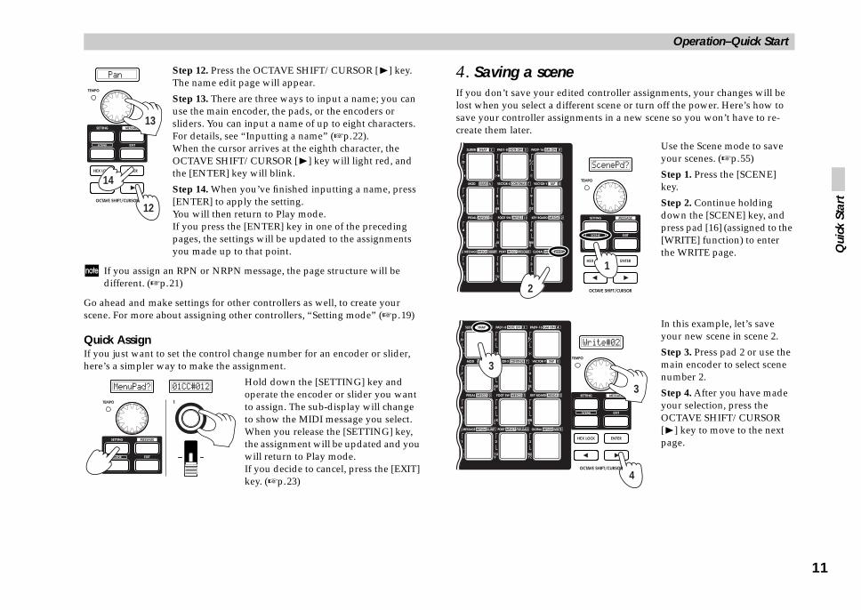
ne edited controller assignments, your changes will be different scene or turn off the power. Here’s how to signments in a new scene so you won’t have to re-
Use the Scene mode to save your scenes. (☞p.55)
Step 1. Press the [SCENE] key.
Step 2. Continue holding down the [SCENE] key, and press pad [16] (assigned to the [WRITE] function) to enter the WRITE page.
In this example, let’s save your new scene in scene 2.
Step 3. Press pad 2 or use the main encoder to select scene number 2.
Step 4. After you have made your selection, press the OCTAVE SHIFT/CURSOR [®] key to move to the next page.
1
4
3
Qui
ck S
tart
Step 12. Press the OCTAVE SHIFT/CURSOR [®] key.The name edit page will appear.
Step 13. There are three ways to input a name; you can use the main encoder, the pads, or the encoders or sliders. You can input a name of up to eight characters. For details, see “Inputting a name” (☞p.22).When the cursor arrives at the eighth character, the OCTAVE SHIFT/CURSOR [®] key will light red, and the [ENTER] key will blink.
Step 14. When you’ve finished inputting a name, press [ENTER] to apply the setting.You will then return to Play mode.If you press the [ENTER] key in one of the preceding pages, the settings will be updated to the assignments you made up to that point.
If you assign an RPN or NRPN message, the page structure will be different. (☞p.21)
Go ahead and make settings for other controllers as well, to create your scene. For more about assigning other controllers, “Setting mode” (☞p.19)
Quick AssignIf you just want to set the control change number for an encoder or slider, here’s a simpler way to make the assignment.
Hold down the [SETTING] key and operate the encoder or slider you want to assign. The sub-display will change to show the MIDI message you select.When you release the [SETTING] key, the assignment will be updated and you will return to Play mode.If you decide to cancel, press the [EXIT] key. (☞p.23)
4. Saving a sceIf you don’t save yourlost when you select a save your controller ascreate them later.
12
14
13
2
3

Operation–Quick Start
1
e sets on your computerLibrarian software, the twelve scenes stored in the on your computer as a set for editing and data
Data transfer to and from the Editor Librarian software is performed in the Scene mode DUMP page. (☞p.53)Step 1. Press the [SCENE] key. The main display indicates “ScenePd?”
Step 2. Continue holding down the [SCENE] key, and press pad 14 (assigned to the [DUMP] function).You will enter the DUMP page.
Editor Librarian software, and press the he scene set from the KONTROL49’s memory.on to name the scene set and save it as a file. A file be loaded into the KONTROL49 whenever
itor Librarian software, refer to “Editor Librarian ncluded CD-ROM.
1
2
The page in which you edit the scene name will appear.
Step 5. Input a scene name using the main encoder, the pads, or the encoders or sliders.You can input a name of up to eight characters. For details, see “Inputting a name” (☞p.22).
Step 6. When you’ve finished inputting the name, press the OCTAVE SHIFT/CURSOR [®] key or the [ENTER] key to proceed to the next page.
Step 7. This page asks you for confirmation. To save the scene, press the [ENTER] key.When the scene has been saved, the main display will indicate “Complete” and you will return to Play mode.
If you decide to cancel mid-way through the Save procedure, press the [EXIT] key.
5. Managing scenUsing the included Editor KONTROL49 can be savedmanagement.
Start up the KONTROL49“Receive” button to load tThen press the “Save” buttyou create in this way canneeded. For details on using the Edsoftware manual” on the i
6
5
7
2

Operation–Play mode
13
ollersuse seven types of controllers.
slidersmit the assigned message each time you operate them.
encoder or slider, its sub-display shows the current on the power, the names assigned to the encoders are message has been assigned, the display indicates
ge assign (Pan message)
er a slider or encoder from this state, the values of played. For the controller you are not operating, the sition is displayed. assigned, “---” is displayed.
the sub-displays will change depending on the With the default settings, this will be green when you d when you operate an encoder.
l of time elapses after you operate the controller, the ast-operated controller will appear.
will remember the most recent value you have set function, which is already saved as part of the scene)
ary encoders, in every scene. This information is l the power is turned off.
Slider Encoder Slider
HEX LOCK key On (hexadecimal display)ecimal display)
Play
mod
e
Play modeIn Play mode, you can use the KONTROL49 to control connected MIDI equipment or soft synthesizers and DAW software on your computer.
When you power-on the KONTROL49 it will always start up in Play mode.The main display will show the current scene name. Normally, it will start up with the scene that was last selected when you turned off the power.
In this state when you operate the main encoder, pads, vector joystick, pitch bend & mod wheels, switch 1/2, or pedal, the main display will show the MIDI message assigned to that controller and its value. (☞“Using the controllers”)
The sub-displays will show the name assigned to each encoder. When you operate an encoder or slider, the sub-display will show the values of both controllers.When a certain interval of time elapses after you operate the controller, the display will switch to the name that is assigned to the last-operated controller.
Normally, each sub-display will show either the encoder name or the slider name. You can only see one name at a time, however. If you want to check the name that is not currently displayed, press the [ENTER] key.
You can change the backlight color of main display and sub-displays. (☞p.46 “Setting mode–[16] GLOBAL (Global setting)”)
Using the contrIn Play mode you can
1. Encoders andThese controllers trans
DisplayWhen you operate an value. When you turn displayed. If no MIDI “NoAssign.”
Example: Control chan
When you operate eithboth controllers are disvalue of the current poIf no MIDI message is
The backlight color of controller you operate.operate a slider, and re
When a certain intervaname assigned to the l
The KONTROL49(the value - not thefor each of the rotretained only unti
If fixed time passes,
If controller is operated (Value display) The name you set is displayed.
Encoder
HEX LOCK key Off (d

Operation–Play mode
1
e pad will light red once when the message is
ned main display will show the contents of the
e message.
ned, the pad will light green. If the pad operation l light orange when you press the pad to transmit again light green when a value of 0 is eration is set to Toggle, the pad will alternate each time you press it.
status of the pads. (☞p.46 “Setting mode–[16] ing)”)
tingsessage to a trigger pad. For details, see “Setting 1–8 assignment)” (☞p.24) or “Setting mode–[4] ignment)” (☞p.26).
-MIDI port from which the assigned MIDI For details, see “Setting mode–[15] USB-MIDI etting)” (☞p.44).
illumination for when a MIDI message is see “Setting mode–[16] GLOBAL (Global
lue
HEX LOCK key On (hexadecimal display)al display)
MIDI message Value
4
If you hold down the [EXIT] key while operating a controller, the sub-display indication will not switch to the name of the assigned setting; the controller value will continue to be displayed. This lets you edit a setting accurately while watching its actual value.
You can change the backlight color of the sub-displays. (☞p.46 “Setting mode–[16] GLOBAL (Global setting)”)
Encoder and slider-related settings• You can assign a MIDI message to an encoder. For details, see “Setting
mode–[1] ENCODER (Encoder assignment)” (☞p.20).
• You can assign a MIDI message to a slider. For details, see “Setting mode–[2] SLIDER (Slider assignment)” (☞p.24).
• You can specify the USB-MIDI port from which the assigned MIDI message is transmitted. For details, see “Setting mode–[15] USB-MIDI PORT (USB-MIDI Port setting)” (☞p.44).
2. Trigger padsWhen you press a pad, it will transmit the assigned note data or control change.Pads to which note data is assigned will also transmit velocity. (“Setting mode–[3] PAD 1–8 (PAD 1–8 assignment)” (☞p.24) or “Setting mode–[4] PAD 9–16 (PAD 9–16 assignment)” (☞p.26))Pads to which a control change is assigned will transmit a value of either 0 or 127.
Display
If note data is assignedWhen you press a pad, the main display will show the transmitted note number and velocity value.
If note data is assigned, thtransmitted.
If a control change is assigWhen you press a pad, thetransmitted control chang
If a control change is assigis set to Momentary, it wila value if 127. (It will oncetransmitted.) If the pad opbetween green and orange
You can change the litGLOBAL (Global sett
Trigger pad-related set• You can assign a MIDI m
mode–[3] PAD 1–8 (PADPAD 9–16 (PAD 9–16 ass
• You can specify the USBmessage is transmitted. PORT (USB-MIDI Port s
• You can specify the padtransmitted. For details,setting)” (☞p.46).
Note number Velocity
HEX LOCK key On (hexadecimal display)HEX LOCK key Off (decimal display)
Note number Velocity
MIDI message Va
HEX LOCK key Off (decim

Operation–Play mode
15
ed settingsDI message to the left/right direction of the vector see “Setting mode–[7] VECTOR-X (Vector-X 1).
DI message to the up/down direction of the vector see “Setting mode–[8] VECTOR-Y (Vector-Y 2).
USB-MIDI port from which the assigned MIDI ed. For details, see “Setting mode–[15] USB-MIDI rt setting)” (☞p.44).
od Wheelse controllers, the assigned MIDI message will be be assigned either to transmit the same parameter for downward range, or to transmit separate parameters wnward ranges.
Pitch Bend or Mod Wheel controllers, the contents of ar in the main display.
assigned MIDI message, you can turn the [HEX red) to see the contents of the MIDI message in
ge Value
If channel aftertouch is assigned(hexadecimal display)is assigned
MIDI message Value
Play
mod
e
3. Vector joystickWhen you move the vector joystick, it will transmit the assigned MIDI message. You can assign MIDI messages to the up/down (Y) and left/right (X) directions.For the up/down/left/right directions, the assigned MIDI message will be transmitted with a value in the range of 0–127.
DisplayWhen you operate the vector joystick, the main display will show the message that is transmitted.
If you’ve assigned a control change, you can turn the [HEX LOCK] key on (lit red) to see the contents of the MIDI message in hexadecimal.
When the vector joystick is operatedIf a control change is assigned, a value in the range of 0–127 is displayed.
If no MIDI message is assigned (NoAssign), the main display will not change even if you operate the vector joystick. Instead, the display will continue to show the scene name.
Vector joystick-relat• You can assign a MI
joystick. For details,assignment)” (☞p.3
• You can assign a MIjoystick. For details,assignment)” (☞p.3
• You can specify the message is transmittPORT (USB-MIDI Po
4. Pitch Bend, MWhen you operate thetransmitted. Bend can the entire upward andfor the upward and do
DisplayWhen you operate thethe message will appe
Depending on theLOCK] key on (lithexadecimal.
X
Y
Value of X directions
If control change is assigned
Value of Y directions
MIDI messa
If pitch bend
Operation–Play mode
1
been assigned (NoAssign), pressing switches 1/2 tion in the main display (it will continue to show
rameter assignment mode, the switch will light mit a value of 127.
e-parameter assignment mode, the value can be ch 1 and switch 2 simultaneously.
gsto switches 1/2. For details, see “Setting mode–[9] ssignment)” (☞p.32).
ort on which MIDI messages will be transmitted. mode–[15] USB-MIDI PORT (USB-MIDI Port
k/SWITCH jack)e will be transmitted when you operate a foot
l connected to the PEDAL jack or SWITCH jack.ransmit a value in the range of 0–127. Operating value of either 0 or 127.
cted pedal, the main display will show the
Value
s assignedlay)
MIDI message Value
If program change is assigned(hexadecimal display)
Value
If damper is assigned assigned
MIDI message Value
6
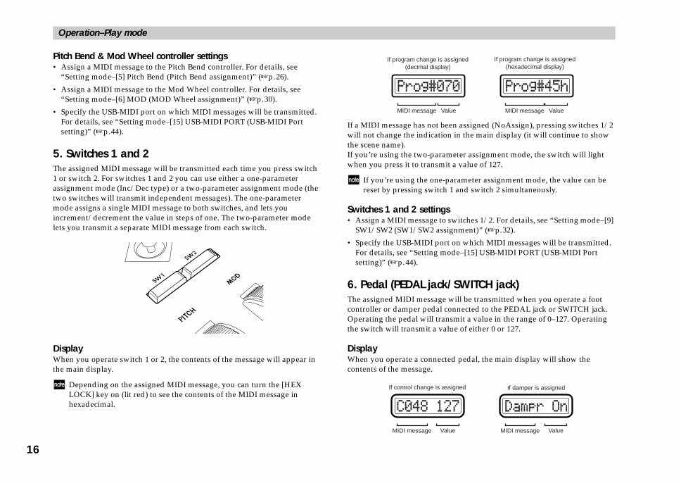
Pitch Bend & Mod Wheel controller settings• Assign a MIDI message to the Pitch Bend controller. For details, see
“Setting mode–[5] Pitch Bend (Pitch Bend assignment)” (☞p.26).
• Assign a MIDI message to the Mod Wheel controller. For details, see “Setting mode–[6] MOD (MOD Wheel assignment)” (☞p.30).
• Specify the USB-MIDI port on which MIDI messages will be transmitted. For details, see “Setting mode–[15] USB-MIDI PORT (USB-MIDI Port setting)” (☞p.44).
5. Switches 1 and 2The assigned MIDI message will be transmitted each time you press switch 1 or switch 2. For switches 1 and 2 you can use either a one-parameter assignment mode (Inc/Dec type) or a two-parameter assignment mode (the two switches will transmit independent messages). The one-parameter mode assigns a single MIDI message to both switches, and lets you increment/decrement the value in steps of one. The two-parameter mode lets you transmit a separate MIDI message from each switch.
DisplayWhen you operate switch 1 or 2, the contents of the message will appear in the main display.
Depending on the assigned MIDI message, you can turn the [HEX LOCK] key on (lit red) to see the contents of the MIDI message in hexadecimal.
If a MIDI message has notwill not change the indicathe scene name).If you’re using the two-pawhen you press it to trans
If you’re using the onreset by pressing swit
Switches 1 and 2 settin• Assign a MIDI message
SW1/SW2 (SW1/SW2 a
• Specify the USB-MIDI pFor details, see “Setting setting)” (☞p.44).
6. Pedal (PEDAL jacThe assigned MIDI messagcontroller or damper pedaOperating the pedal will tthe switch will transmit a
DisplayWhen you operate a connecontents of the message.
MIDI message
If program change i(decimal disp
MIDI message
If control change is

Operation–Play mode
17
mode–[13] MAIN ENC (Main Encoder assignment)”
mpo defaults to 120 when you turn the power on.
signed, you can hold down the [SETTING] key and oder to adjust the first decimal place of the tempo. At e of adjustment will be 20.0–300.0.e & Bank Select is assigned, you can hold down the d turn the main encoder to edit the Bank Select MSB
assigned to the main encoder, the tempo of the MIDI e main display when you turn the main encoder. The per left of the main encoder will blink at quarter-note d MIDI Clock tempo.
change or program change & bank select is assigned e program change number will appear in the main the main encoder.
gsage to the main encoder. For details, see “Setting
C (Main Encoder assignment)” (☞p.40).
I port on which MIDI messages will be transmitted. ing mode–[15] USB-MIDI PORT (USB-MIDI Port
mode [8] Tap, you can set the desired tempo by the corresponding interval. For details, see “Message p tempo message)” (☞p.51).
Play
mod
e
If no MIDI message is assigned (NoAssign), the main display will not change even if you operate the pedal (the display will continue to show the scene name).
Pedal-related settings• You can assign a MIDI message to the pedal. For details, see “Setting
mode–[10] PEDAL (Pedal assignment)” (☞p.35).
• You can specify the USB-MIDI port from which the assigned MIDI message is transmitted. For details, see “Setting mode–[15] USB-MIDI PORT (USB-MIDI Port setting)” (☞p.44).
• Specify the polarity of the connected pedal switch, and the effective range of the pedal. For details, see “Setting mode–[16] GLOBAL (Global setting)” (☞p.46).
7. Main encoderYou can use the main encoder to adjust the tempo of the MIDI Clock or to transmit program changes.If a connected device or application is synchronized to MIDI Clock messages from the KONTROL49, you can use the main encoder to control the tempo. The tempo range is Clock Off and 020–300. If you set the encoder to Clock Off, MIDI Clock will not be transmitted. MIDI Clock messages are transmitted from the port you specify for MIDI message transmission in Message mode (☞p.44 “[15] USB-MIDI PORT (USB-MIDI Port setting)”).If the main encoder is assigned to transmit program changes, any value in the range of 1–128 can be transmitted. You can also specify that the program change be transmitted together with a Bank Select message.Depending on the assignment of the main encoder, the [SETTING] key, [MESSAGE] key, and [EXIT] key will operate as follows:
For details, see “Setting(☞p.40).
The MIDI Clock te
If TempoChg is asturn the main encthis time the rangIf Program Chang[SETTING] key anor LSB.
DisplayWhen tempo change isClock will appear in thTEMPO LED at the upintervals of the specifie
When either program to the main encoder, thdisplay when you turn
Main encoder settin• Assign a MIDI mess
mode–[13] MAIN EN
• Specify the USB-MIDFor details, see “Settsetting)” (☞p.44).
By using Messagetapping pad [8] atmode–[8] TAP (Ta
MIDI message [SETTING] key [MESSAGE] key [EXIT] key
NoAssign No change
TempoChg Edit the decimal place Switch the tempo when released
Always display the Tempo
ProgChg No change Transmit Prog# when released
Always display the Prog#
PChg&BS Edit MSB/LSB Transmit Prog#&BS when released
Always display the Prog#

Operation–Play mode
1
gsI channel on which note data is transmitted. For e–[12] KEYBOARD (Keyboard setting)” (☞p.38).
yboard in semitone steps. For details, see “Setting (Keyboard setting)” (☞p.38).
city curve. For details, see “Setting mode–[12] setting)” (☞p.38).
-MIDI port from which the note data is see “Setting mode–[15] USB-MIDI PORT (USB-.44).
8
8. KeyboardWhen you play notes on the keyboard, note messages are transmitted on the keyboard’s MIDI channel (☞p.38).
Octave settingYou can use the OCTAVE SHIFT/CURSOR [√]/[®] keys to shift the pitch of the keyboard in steps of an octave. If you want to return to the ±0 (normal) setting, press the [√] and [®] keys simultaneously.
1 Each time you press the [®] key the pitch will shift upward one octave. The color of the [®] key indicates the current setting.
Unlit: ±0 octavesGreen: +1 octaveOrange: +2 octavesRed: +3 octaves
2 Each time you press the [√] key the pitch will shift downward one octave. The color of the [√] key indicates the current setting.
Unlit: ±0 octavesGreen: –1 octaveOrange: –2 octavesRed: –3 octaves
Keyboard-related settin• You can specify the MID
details, see “Setting mod
• You can transpose the kemode–[12] KEYBOARD
• You can change the veloKEYBOARD (Keyboard
• You can specify the USBtransmitted. For details,MIDI Port setting)” (☞p
C4 C5 C6 C7 C8C3C2C1 C9C0
Octave: ±0
Octave: -1
Octave: -2
Octave: -3 Octave: +1
Octave: +2
Pitch range adjusted by the Octave Shift keys
Octave: +3
C-1

Operation–Setting mode
19
ter settingsor setting Global parameters. These settings are saved u exit the page or select a different scene.
VE SHIFT/CURSOR keys, [ENTER] keyCTAVE SHIFT/CURSOR [√]/[®] keys act as cursor parameters.the [SETTING] key and press a pad to enter a page in ill light green to indicate the direction(s) in which not move in a direction whose key is dark or lit red.eginning of the selected page by holding down the he [√] key.
You can move toward the right to another parameter
You can move toward the left to another parameter
last parameter, the [ENTER] key will blink. Press the the setting and return to Play mode. If you press rive at the last parameter, your settings up to that nd you will return to Play mode. you decide to discard your changes before pressing
e ContentPedal settings, backlight color, pad illumination settings (☞p.46)
Setti
ng m
ode
Setting modeIn Setting mode you can set both the Scene parameters (the assignment of each controller, etc.) and the Global parameters (overall settings for the entire KONTROL49).
Setting mode is divided into sixteen pages.Hold down the [SETTING] key (the main display shows “MenuPad?”) and press one of the pads listed below to move to the corresponding page of parameter settings.If you hold down the [EXIT] key and press the [SETTING] key, the main display will show “MenuPad?” and the KONTROL49 will wait for you to press one of the pads to select a page.
Scene parameter settingsPad [1] through pad [15] access pages for setting Scene parameters. After you edit these settings, you will need to save them in Scene mode.
Global paramePad [16] access pages fautomatically when yo
About the OCTAkey, and [EXIT]In Setting mode, the Okeys to move betweenWhen you hold down this mode, the key(s) wyou can move. You canYou can return to the b[®] key and pressing t
:
:
When you arrive at the[ENTER] key to apply[ENTER] before you arpoint will be applied aPress the [EXIT] key if[ENTER].
Pad No. Page ContentPad [1] Encoder assignment Assign messages to encoders (☞p.20)
Pad [2] Slider assignment Assign messages to sliders (☞p.24)
Pad [3] PAD 1–8 assignment Assign messages to pads [1]–[8] (☞p.24)
Pad [4] PAD 9–16 assignment Assign messages to pads [9]–[16] (☞p.26)
Pad [5] Pitch Bend assignment Assign messages to Pitch Bend wheel (☞p.26)
Pad [6] Mod Wheel assignment Assign messages to Mod wheel (☞p.30)
Pad [7] Vector-X assignment Assign messages to the left/right direction of the vec-tor joystick (☞p.31)
Pad [8] Vector-Y assignment Assign messages to the forward/backward direction of the vector joystick (☞p.32)
Pad [9] SW1/2 assignment Assign messages to Switch 1/Switch 2 (☞p.32)
Pad [10] Pedal assignment Assign messages to the connected foot controller (☞p.35)
Pad [11] Foot SW assignment Assign messages to connected damper pedal or pedal switch (☞p.36)
Pad [12] Keyboard assignment Assign messages to Keyboard MIDI channel (☞p.38)
Pad [13] Main Enc assignment Assign messages to main encoder (☞p.40)
Pad [14] Message assignment Assign messages to Message mode pad [9]–[16] (☞p.41)
Pad [15] USB-MIDI Port setting Make USB-MIDI port settings (☞p.44)
Pad No. Pag
Pad [16] Global setting
(GREEN)(RED)
(GREEN) (RED)

Operation–Setting mode
2
lit, you can also use these to select an encoder to
IFT/CURSOR [®] key to proceed to “Message DI message).
r or the pads to select the MIDI message you want
assigned to the selected encoder. If you select NTER] key (blinking) to update the setting.
Change)control change message. (☞p.56 “Available MIDI
RPN to the encoder. If you select NRPN or RPN, ify the “MSB” and “LSB” for the controller. For ode–Assigning NRPN or RPN” (☞p.21).
or RPN, and MIDI channel values can also be ng the encoder itself (or the slider if making a make a setting for a different encoder (or slider), oder (or slider). The display will show the setting
er) you operated, and the display backlight color ly.
X LOCK] key and input hexadecimal values.
(Green)(Red)
0
[1] ENCODER (Encoder assignment)The Encoder assignment page lets you assign MIDI messages to the rotary encoders, specify the MIDI channel on which the messages will be transmitted, etc. You can assign a control change (CC#), RPN, or NRPN message to each encoder.
1 Hold down the [SETTING] key and press pad [1].You will be in the Encoder assignment page, and the [SETTING] key and pad [1] will light. The main display indicates “Encoder Select,” prompting you to select the encoder to assign.
Each sub-display indicates the MIDI message assigned to the corresponding encoder, and the MIDI transmit channel.
The selectable parameters or values will blink in the main display.
If you want to check the MIDI messages assigned to an encoder or slider, enter Setting mode and check the sub-displays.
2 Use the main encoder to choose the encoder to which you want to assign a MIDI message. Alternatively, you can select the desired encoder simply by turning it directly.
If SW1 and 2 are bothassign.
3 Press the OCTAVE SHSelect” (select the MI
4 Use the main encodeto assign.
NoAsgn (No Assign)No MIDI message is NoAsgn, press the [E(☞Step 9)
CC#000-127 (ControlAssigns the selected messages”)
NRPN, RPNAssigns an NRPN oryou will need to specdetails, see “Setting m
Control change, NRPNset by directly operatislider assignment). Tosimply move that encfor the encoder (or slidwill change according
You can press the [HE
MIDI channel Control change numberMIDI message type

Operation–Setting mode
21
N or RPNRPN in “Message Select,” you need to set the “MSB,” nnel” for the message.
meter Number) is a type of message used to make ited to devices made by a single manufacturer.
nclude RPN Fine Tune [MSB=00, LSB=01], RPN , LSB=02], and RPN Pitch Bend Range [MSB=00,
d Parameter Number) is a type of message that can ument manufacturers and devices.
ct,” select NRPN or RPN.se by turning the main encoder toward the right
127.
E SHIFT/CURSOR [®] to proceed to “MSB.”
oder or the pads to input the “MSB” value. The range tands for “Most Significant Byte.”
E SHIFT/CURSOR [®] key to proceed to “LSB.”
(Green)(Green)
(Green)(Green)
Setti
ng m
ode
5 Press the OCTAVE SHIFT/CURSOR [®] key to proceed to “MIDI Channel” (specify the MIDI channel).
6 Use the main encoder or the pads to select the MIDI channel on which the MIDI message will be transmitted. The range is 1–16 (ch). (☞p.4 “About the trigger pad functions–Input numerical values”)
7 Press the OCTAVE SHIFT/CURSOR [®] to proceed to “Name,” where you can specify a name for the encoder.
8 Specify the desired name for the assignment. In Play mode, the name you specify is shown in the sub-display. For the procedure, see “Inputting a name” (☞p.22).
9 Press the [ENTER] key.The setting will be updated, and you will return to Play mode.
If you want to keep the changes you’ve made, save them in Scene mode. If you turn off the power or select a different scene without saving, your changes will be discarded. For details, see “Scene mode–[16] WRITE” (☞p.55).
■ Assigning NRPIf you select NRPN or “LSB,” and “MIDI Cha
RPN (Registered Parasettings that are not limMessages of this type iCoarse Tune [MSB=00LSB=00].NRPN (Non Registerebe freely used by instr
1 In “Message SeleYou can select thefollowing CChg#
2 Press the OCTAV
3 Use the main encis 0–127. “MSB” s
4 Press the OCTAV
(Green)(Green)
(Green)(Green)

Operation–Setting mode
eely assign a name to the parameter you assigned o, in Scene mode you can freely assign a name to
.
g characters.
ain display. If the cursor is located on a character, se the OCTAVE SHIFT/CURSOR [√][®] keys to
ut text; using the main encoder, using the trigger s or sliders. These three input methods are
to input texthoose characters in the order of (blank), A–Z, a–ove the cursor to the position at which you want
se the main encoder to choose a character.
22
5 Use the main encoder or the pads to input the “LSB” value. The range is 0–127.
6 Press the OCTAVE SHIFT/CURSOR [®] key to proceed to “MIDI Channel” (specify the MIDI channel).
7 Use the main encoder or the pads to select the MIDI channel on which the assigned MIDI message will be transmitted. The range is 1–16 (ch). (☞p.4 “About the trigger pad functions–Input numerical values”)
8 Press the OCTAVE SHIFT/CURSOR [®] to proceed to “Name,” where you can specify a name for the encoder.
9 Specify the desired name for the assignment. In Play mode, the name you specify is shown in the sub-display. For the procedure, see “Inputting a name” (☞p.22).
10 Press the [ENTER] key.The setting will be updated, and you will return to Play mode.
If you want to keep the changes you’ve made, save them in Scene mode. If you turn off the power or select a different scene without saving, your changes will be discarded. For details, see “Scene mode–[16] WRITE” (☞p.55).
Inputting a nameIn Setting mode you can frto an encoder or slider. Alsthe scene you’ve assigned
Available charactersYou can input the followin
Moving the cursorA cursor is shown in the mthat character will blink. Umove the cursor.
Inputting textThere are three ways to inppads, or using the encoderexplained below.
■ Using the main encoder Turn the main encoder to cz, 1–9, 0, and symbols. Mto input a character, and u
(Green)(Green)
(Green)(Green)

Operation–Setting mode
23
control changes shortcut for assigning a new control change message r if making a slider assignment). This method is valid slider which is already assigned to a control change
is method for an encoder or slider to which you have r RPN.
ld down the [SETTING] key and turn the desired if making a slider assignment) to select a new control
ill show the new assignment for the encoder or
change assignment will be updated when you release y or operate a different controller. If you decide to
[EXIT] key before you release the [SETTING] key.
will still be set to the “MIDI Channel” specified in the nt Slider assignment page.
p the changes you’ve made, save them in Scene mode. power or select a different scene without saving, your scarded. For details, see “Scene mode–[16] WRITE”
hannel Control change numberMIDI message type
Setti
ng m
ode
■ Using the trigger pads to input textAn alphanumeric character, symbol, or blank is assigned to each pad. Insert (insert a blank at the cursor location), Delete (delete the character at the cursor location and tighten up the subsequent characters), and Clear (erase the character at the cursor location) functions are also provided. The selected character will alternate each time you strike a pad [5]–[8] or [10]–[16]. Move the cursor to the position at which you want to input a character, and use the trigger pads to input or edit characters.
■ Using the encoders and sliders to input textRegardless of the cursor location, you can use the sliders and encoders to input the characters shown in the display. Use slider 1 or encoder 1 to input the first character (counting from the left edge) of the display. Use slider 2 or encoder 2 to input the second character of the display. In this way, sliders 1–8 or encoders 1–8 will edit the eight characters shown in the display.However, you’ll need to use sliders 1–8 to input the name of a parameter assigned to an encoder. Likewise, you’ll need to use encoders 1–8 to input the name of a parameter assigned to a slider.
Quick-assign forIn Play mode, there’s ato an encoder (or slideonly for an encoder ormessage.
You cannot use thassigned NRPN o
1 In Play mode, hoencoder (or sliderchange message.The sub-display wslider.
2 The new control the [SETTING] kecancel, press the
The MIDI channelEncoder assignme
If you want to keeIf you turn off thechanges will be di(☞p.55).
[1]
[5]
[9]
[13] [14] [15] [16]
[2]
[10]
[6]
[3]
[11]
[7]
[4]
[8]
[12]
MIDI c

Operation–Setting mode
2
gh 8 will show the MIDI transmit channel, MIDI nsmission setting for each pad.
erate the fifth encoder or slider, PAD#5 will be display will indicate “PAD# 05”.
r or the pads to select the pad that you want to selection using the pads, simply press the desired
assignment will blink.
lit, you can also use these switches to select a pad
s where you specify the MIDI message type and ol change number, you can use the bered encoder or slider to select a parameter or nient to use the slider to make large changes in a oder to make fine adjustments.
IFT/CURSOR [®] key to proceed to “Message DI message).
Note numberor
Control change number
I message type Pad operation type
(Green)(Red)
4
[2] SLIDER (Slider assignment)In the Slider assignment page, you can assign MIDI messages to sliders and specify the MIDI channel on which the messages will be transmitted, etc.You can assign a control change (CC#), RPN, or NRPN message to each slider.
1 Hold down the [SETTING] key and press pad [2].You will be in the Slider assignment page, and the [SETTING] key and pad [2] will light. The main display indicates “Slider Select” (select the slider to assign). The messages you can assign to a slider and the assignment procedure are the same as for an encoder. For details, refer to “Encoder assignment” (☞p.20). You can use the Quick Assign procedure for sliders as well. For details, refer to “Quick-assign for control changes” in “Encoder assignment.”
[3] PAD 1–8 (PAD 1–8 assignment)PAD 1–8 assignment lets you assign MIDI messages to pads 1 through 8, and specify the channels on which these messages will be transmitted.You can assign a note message or a control change (CC#) to each pad.If you assign a control change, the message will be transmitted with a value of either 0 or 127.Pad velocity settings are maintained separately for each scene. As the pad velocity type, you can choose either to transmit a velocity value that corresponds to the force with which you strike the pad, or to transmit a fixed value regardless of your striking force.
1 Hold down the [SETTING] key and press pad [3].Now you can make pad [1]–[8] assignments. The [SETTING] key and pads [1] through [8] will light/blink. The main display will indicate “PAD# 01” (select the pad that you want to assign).
Sub-displays 1 throumessage, and pad tra
For example if you opselected and the main
2 Use the main encodeassign. To make yourpad.The pad selected for
If both SW1 and 2 areto assign.
In the following pagenote number or contrcorrespondingly-numedit a value. It’s convevalue, and use the enc
3 Press the OCTAVE SHSelect” (select the MI
MIDI channel MID

Operation–Setting mode
25
oder or the pads to select the MIDI transmit channel. (ch). (☞p.4 “About the trigger pad functions–Input ”)
E SHIFT/CURSOR [®] key to proceed to “PAD type of pad operation).
oder to specify the type of operation that occurs when .
y)e is assigned to the pad, pressing the pad will ned control change message with a value of 127, and ansmit a value of 0. is assigned to the pad, pressing the pad will transmit leasing it will transmit a note-off.
e is assigned to the pad, the assigned MIDI message d alternately with a value of 127 and a value of 0 each e pad. is assigned to the pad, a note-on message and a note-e transmitted alternately each time you press the
E SHIFT/CURSOR [®] key to proceed to “Velocity type of velocity).
oder to select the velocity type.
Sens)elocity value will depend on how strongly you strike
hoose VelSens, press the [ENTER] key (blinking) to
(Green)(Green)
Setti
ng m
ode
4 Use the main encoder to select the type of MIDI message.
NoAssignNo MIDI message will be assigned to the selected pad. If you select NoAssign, the setting will be updated when you press the [ENTER] key (blinking). (☞Step 14)
Note# (Note message)Assigns a note message to the selected pad.
CtrlChg# (Control Change)A control change message will be assigned to the switch. If you selected CtrlChg#, select the control change number. (☞p.30 “Assigning a control change”)
5 Press the OCTAVE SHIFT/CURSOR [®] key to proceed to “Note Select” (specify a note number) or “Control Change Select” (specify a control change number).
6 Use the main encoder or the pads to select a note number or control change number. The range is 0–127. (☞p.4 “About the trigger pad functions–Input numerical values,” ☞p.56 “Available MIDI messages”)
If you’re assigning a note message, press a note on the keyboard to assign that note number to the current pad.
7 Press the OCTAVE SHIFT/CURSOR [®] key to proceed to “MIDI Channel” (specify the MIDI channel).
8 Use the main encThe range is 1–16numerical values
9 Press the OCTAVType” (select the
10 Use the main encyou press the pad
Momt (MomentarIf a control changtransmit the assigreleasing it will trIf a note messagea note-on, and re
Tgle (Toggle)If a control changwill be transmittetime you press thIf a note messageoff message will bpad.
11 Press the OCTAVType” (select the
12 Use the main enc
VelSens (Velocity The transmitted vthe pad. (If you csave the setting.)
(Green)(Green)
When assigning a control change
When assigning a note message
(Green)(Green)

Operation–Setting mode
2
ch Bend assignment)IDI messages that will be transmitted when you oller up or down, and specify the MIDI channel re transmitted. If desired, you can assign separate ard and downward ranges of movement.
MIDI message to the full range (up/
gle MIDI message to be transmitted by the full e Pitch Bend controller. You can assign pitch bend, , velocity, or a control change (CC#).
TING] key and press pad [5]. the Pitch Bend assignment. The [SETTING] key . The main display indicates “Assignment Select.” is where you choose whether the full range of own) will transmit a single MIDI message, or downward movement will transmit separate
r to specify the Pitch Bend assignment selection. ose UP-DOWN.
6
ConstantThe fixed velocity value you specify will be transmitted when you strike the pad.
13 If you set “Velocity Type” to Constant, press the OCTAVE SHIFT/CURSOR [®] key to move to “Constant” (the velocity value setting), and use the main encoder to specify the desired velocity value in a range of 1–127.
This constant velocity setting applies to all pads 1–8 and 9–16.
14 Press the [ENTER] key.The settings will be updated and you will return to Play mode.In Play mode, pads to which a control change is assigned will light green, and pads to which a note message is assigned or for which NoAssign is selected will be dark.
If you want to keep the new assignments, you must save them in Scene mode. If you turn off the power or select a different scene without saving, your changes will be lost. (☞p.55 “Scene mode–[16] WRITE”)
[4] PAD 9–16 (PAD 9–16 assignment)PAD 9–16 assignment lets you assign MIDI messages to pads 9 through 16, and specify the channels on which these messages will be transmitted.
1 Hold down the [SETTING] key and press pad [4].Now you can make pad 9–16 assignments.The [SETTING] key and pads [9] through [16] will light or blink. The main display indicates “PAD# 09” (select the pad to assign).The assignments that can be made for pads 9–16 and the procedure are the same as for PAD 1–8. For details, see “PAD 1–8 assignment” (☞p.24).
[5] Pitch Bend (PitHere you can assign the Mmove the Pitch Bend contron which these messages aMIDI messages to the upw
Assigning a single down)Here’s how to assign a sinrange (up and down) of thmaster balance, aftertouch
1 Hold down the [SETNow you can specifyand pad [5] will light“Assignment Select”movement (up and dwhether upward andMIDI messages.
2 Use the main encodeFor this example, cho
(Green)(Green)

Operation–Setting mode
27
ch) aftertouch. If you choose A.Touch, continue by of aftertouch. (☞p.29 “Assigning aftertouch”)
or pad velocity. If you choose Velocity, continue by city type. (☞p.29 “Assigning velocity”)
city, settings such as Key Curve are ignored.
Change) message will be assigned to the switch. If you #, select the control change number. (☞p.30 trol change”)
E SHIFT/CURSOR [®] key to proceed to “MIDI the MIDI channel).
oder or the pads to select the MIDI channel on which e will be transmitted. The range is 1–16 (ch). (☞p.4 r pad functions–Input numerical values”)
] key.e updated, and you will return to Play mode.
p the changes you’ve made, save them in Scene mode. power or select a different scene without saving, your scarded. For details, see “Scene mode–[16] WRITE”
(Green)(Green)
Setti
ng m
ode
UP-DOWNAssign a single MIDI message to the full range of movement (up and down).
UP/DOWNAssign separate MIDI messages to the upward and downward ranges of movement. (☞p.28 “Assigning separate MIDI messages to the up/down ranges”)
3 Press the OCTAVE SHIFT/CURSOR [®] key to proceed to “Message Select” (select the MIDI message).
4 Use the main encoder to select the MIDI message you want to assign.
NoAssignNo MIDI message will be assigned to up/down movement of the Pitch Bend controller. If you choose NoAssign, continue by pressing the [ENTER] key to apply the setting. (☞Step 7)
PitchBnd (Pitch Bend)Assign pitch bend. If you choose PitchBnd, continue by pressing the OCTAVE SHIFT/CURSOR [®] key to move to “MIDI Channel” (MIDI channel setting). (☞Step 5)In Play mode when you operate the Pitch Bend controller, the main display indicates “PBend---”.
MastrBal (Master Balance)Assign master balance. Master Balance messages [F0, 7F, 7F, 04, 02, vv, mm, F7] (device ID fixed at 7Fh) will be transmitted. If you choose MastrBal, continue by pressing the [ENTER] key to apply the setting. (☞Step 7)In Play mode when you operate the Pitch Bend controller, the main display indicates “MstBl---”.
A.Touch (AfterTouAssign keyboardselecting the type
VelocityAssign keyboardselecting the velo
If you assign Velo
CtrlChg# (ControlA control changeselected CtrlChg“Assigning a con
5 Press the OCTAVChannel” (specify
6 Use the main encthe MIDI messag“About the trigge
7 Press the [ENTERThe setting will b
If you want to keeIf you turn off thechanges will be di(☞p.55).
(Green)(Red)

Operation–Setting mode
2
r to select the MIDI message you want to assign.
ill be assigned to the range you are specifying. If n, continue by pressing the [ENTER] key to apply )
rtouch. If you choose A.Touch, continue by aftertouch. (☞p.29 “Assigning aftertouch”)
ad velocity. If you choose Velocity, continue by type. (☞p.29 “Assigning velocity”)
nge)ssage will be assigned to the switch. If you lect the control change number. (☞p.30 change”)
IFT/CURSOR [®] key to proceed to “MIDI e MIDI channel).
r or the pads to select the MIDI channel on which essage will be transmitted. The range is 1–16 (ch). gger pad functions–Input numerical values”)
(Green)(Green)
(Green)(Green)
8
Assigning separate MIDI messages to the up/down rangesHere’s how to assign separate MIDI messages to the up and down ranges of the Pitch Bend controller. You can assign aftertouch, velocity, or a control change (CC#).
1 Hold down the [SETTING] key and press pad [5] to enter Pitch Bend assignment, and choose UP/DOWN as the “Assignment Select” setting.
2 Press the OCTAVE SHIFT/CURSOR [®] key to proceed to “UP/DOWN Select” (select the range of movement for which you want to make an assignment).
3 Use the main encoder to select whether you want to assign the up or down range of movement.
UPMake an assignment for the up range.
DOWNMake an assignment for the down range.
4 Press the OCTAVE SHIFT/CURSOR [®] key to proceed to “Message Select” (select the MIDI message).
5 Use the main encode
NoAssignNo MIDI message wyou choose NoAssigthe setting. (☞Step 8
A.Touch (AfterTouch)Assign keyboard afteselecting the type of
VelocityAssign keyboard or pselecting the velocity
CtrlChg# (Control ChaA control change meselected CtrlChg#, se“Assigning a control
6 Press the OCTAVE SHChannel” (specify th
7 Use the main encodethe assigned MIDI m(☞p.4 “About the tri
(Green)(Red)

Operation–Setting mode
29
E SHIFT/CURSOR [®] key to proceed to “MIDI the MIDI channel).
E SHIFT/CURSOR [√] key to return to “UP/DOWN e the desired assignment for the other range of 28 “Assigning separate MIDI messages to the up/ps 3–7)
] key.e updated, and you will return to Play mode.
p the changes you’ve made, save them in Scene mode. power or select a different scene without saving, your scarded. For details, see “Scene mode–[16] WRITE”
yor “Message Select,” use “Velocity Type” to specify then apply the setting.
E SHIFT/CURSOR [®] key to move to “Velocity velocity type).
oder to select the type of velocity. priority over the velocity-related settings you make 9–16, and Keyboard Setting. position of the Pitch Bend (or Mod Wheel) controller e velocity values that are transmitted. If the controller y value of 0, the display will indicate “KbdOnVel” or the velocity produced by the keyboard or pad will be
(Green)(Green)
Setti
ng m
ode
8 Press the OCTAVE SHIFT/CURSOR [√] key to return to “UP/DOWN Select,” and make settings for the other range of Pitch Bend controller movement. (☞Steps 3–7)
9 Press the [ENTER] key.The setting will be updated, and you will return to Play mode.
If you want to keep the changes you’ve made, save them in Scene mode. If you turn off the power or select a different scene without saving, your changes will be discarded. For details, see “Scene mode–[16] WRITE” (☞p.55).
■ Assigning aftertouchIf you chose A.Touch for “Message Select,” set “Pressure Type” to select the type of aftertouch, and then proceed to “MIDI Channel” (specify the MIDI channel).
1 Press the OCTAVE SHIFT/CURSOR [®] key to move to “Pressure Type” (select the type of aftertouch).
2 Use the main encoder to select the type of aftertouch.
Ch (Channel Aftertouch)Channel aftertouch applies to all keys being played.In Play mode when you operate the Pitch Bend (or Mod Wheel) controller, the main display will indicate “ChAft---”.
Last (Polyphonic key pressure)Polyphonic key pressure applies aftertouch only to the last-played key if more than one key is being played.In Play mode when you operate the Pitch Bend (or Mod Wheel) controller, the main display will indicate “PyAft---”.
3 Press the OCTAVChannel” (specify
4 Press the OCTAVSelect,” and makmovement. (☞p.down ranges” ste
5 Press the [ENTERThe setting will b
If you want to keeIf you turn off thechanges will be di(☞p.55).
■ Assigning velocitIf you chose Velocity fthe velocity type, and
1 Press the OCTAVType” (select the
2 Use the main encThis setting takesin PAD 1–8, PADIn Play mode, thewill determine thspecifies a velocit“PadOnVel,” andtransmitted.
(Green)(Green)

Operation–Setting mode
3
IFT/CURSOR [®] key to proceed to “MIDI e MIDI channel).
r or the pads to select the MIDI transmit channel. ).
y.dated, and you will return to Play mode.
e changes you’ve made, save them in Scene mode. er or select a different scene without saving, your ded. For details, see “Scene mode–[16] WRITE”
heel assignment)age to assign to the Mod Wheel controller, and which the messages will be transmitted.
velocity, or control change (CC#) messages to the
TING] key and press pad [6]. the Mod Wheel assignment, and the [SETTING] light. The main display indicates “Assignment ignment).
(Green)(Green)
0
KBD (Keyboard)The controller will specify the keyboard velocity.In Play mode, the main display will indicate “KyVel---” when you operate the Pitch Bend (or Mod Wheel) controller.
PAD (Pad)The controller will specify the pad velocity. In this case, the velocity values being controlled by the Pitch Bend (or Mod Wheel) controller are for the note messages transmitted on the MIDI channel specified for the pads.In Play mode, the main display will indicate “PdVel---” when you operate the Pitch Bend (or Mod Wheel) controller.
3 Press the [ENTER] key.The setting will be updated, and you will return to Play mode.
If you want to keep the changes you’ve made, save them in Scene mode. If you turn off the power or select a different scene without saving, your changes will be discarded. For details, see “Scene mode–[16] WRITE” (☞p.55).
■ Assigning a control changeIf you chose CtrlChg# for “Message Select,” use “Control Change Select” to select a control change, and then proceed to “MIDI Channel” (MIDI channel setting).
1 Press the OCTAVE SHIFT/CURSOR [®] key to move to “Control Change Select” (select the control change number).
2 Use the main encoder or pads to select the desired control change number in a range of 0–127.
3 Press the OCTAVE SHChannel” (specify th
4 Use the main encodeThe range is 1–16 (ch
5 Press the [ENTER] keThe setting will be up
If you want to keep thIf you turn off the powchanges will be discar(☞p.55).
[6] MOD (MOD WHere you can select a messselect the MIDI channel onYou can assign aftertouch,Mod Wheel controller.
1 Hold down the [SETNow you can specifykey and pad [6] will Select” (select the ass
(Green)(Red)

Operation–Setting mode
31
Vector-X assignment)MIDI message to the X-axis of the vector joystick.ol change (CC#) message to the X-axis of the vector
ETTING] key and press pad [7].cify the Vector-X assignment, and the [SETTING] key ight. The main display indicates “Message Select”
essage).
oder to select the MIDI message you want to assign.
e will be assigned to the X-axis of the vector joystick.Assign, press the [ENTER] key to apply the setting.
Control Change) message will be assigned to the switch.
oder or pads to select the desired control change e of 0–127.
E SHIFT/CURSOR [®] key to proceed to “MIDI the MIDI channel).
(Green)(Green)
Setti
ng m
ode
2 Use the main encoder to select the MIDI message you want to assign.
NoAssignNo MIDI message will be assigned to the Mod Wheel controller. If you select NoAssign, press the [ENTER] key to apply the setting. (☞Step 5)
A.Touch (AfterTouch)Assign keyboard aftertouch. If you choose A.Touch, continue by selecting the type of aftertouch. (☞p.29 “Assigning aftertouch”)
VelocityAssign keyboard or pad velocity. If you choose Velocity, continue by selecting the velocity type. (☞p.29 “Assigning velocity”)
CtrlChg# (Control Change)A control change message will be assigned to the switch. If you selected CtrlChg#, select the control change number. (☞p.30 “Assigning a control change”)
3 Press the OCTAVE SHIFT/CURSOR [®] key to proceed to “MIDI Channel” (specify the MIDI channel).
4 Use the main encoder or the pads to select the MIDI channel on which the MIDI message will be transmitted. The range is 1–16 (ch). (☞p.4 “About the trigger pad functions–Input numerical values”)
5 Press the [ENTER] key.The setting will be updated, and you will return to Play mode.
If you want to keep the changes you’ve made, save them in Scene mode. If you turn off the power or select a different scene without saving, your changes will be discarded. For details, see “Scene mode–[16] WRITE” (☞p.55).
[7] VECTOR-X (Here you can assign a You can assign a contrjoystick.
1 Hold down the [SNow you can speand pad [7] will l(select the MIDI m
2 Use the main enc
NoAssignNo MIDI messagIf you choose No(☞Step 6)
CChg#000–127 (A control change
3 Use the main encnumber in a rang
4 Press the OCTAVChannel” (specify
(Green)(Green)

Operation–Setting mode
3
in one-parameter modeer mode, either control changes (CC#) or program switches 1 and 2.
TING] key and press pad [9].nd pad [9] will light; now you can make SW1/e main display indicates “Assignment Select” t method).t” you can choose either one-parameter two-parameter assignment mode.
r to select the assignment mode for switches 1 and
C-DEC.
eter mode) message to switches 1 and 2.
meter mode)I messages to switch 1 and switch 2.
IFT/CURSOR [®] key to proceed to “Message DI message).
r to select the type of MIDI message.
ill be assigned to switches 1 and 2. If you choose [ENTER] key (blinking) to apply the setting.
(Green)(Red)
2
5 Use the main encoder or the pads to select the MIDI channel on which the assigned MIDI message will be transmitted. The range is 1–16 (ch). (☞p.4 “About the trigger pad functions–Input numerical values”)
6 Press the [ENTER] key.The setting will be updated, and you will return to Play mode.
If you want to keep the changes you’ve made, save them in Scene mode. If you turn off the power or select a different scene without saving, your changes will be discarded. For details, see “Scene mode–[16] WRITE” (☞p.55).
[8] VECTOR-Y (Vector-Y assignment)Here you can assign a MIDI message to the Y-axis of the vector joystick.In the same way as for the X-axis, you can assign a control change (CC#) message to the Y-axis of the vector joystick.
1 Hold down the [SETTING] key and press pad [8].Now you can specify the Vector-Y assignment, and the [SETTING] key and pad [8] will light. The main display indicates “Message Select” (select the MIDI message). The procedure for assigning the Y-axis of the vector joystick is the same as for the X-axis. For details, refer to “Vector-X assignment” (☞p.31)
[9] SW1/SW2 (SW1/SW2 assignment)Here you can assign MIDI messages to switches 1 and 2, and specify the MIDI transmit channel.Switches 1 and 2 can be used either in one-parameter mode (Inc/Dec operation) or in two-parameter mode (separate assignments for each switch).
Using the switches If you choose one-parametchanges can be assigned to
1 Hold down the [SETThe [SETTING] key aSW2 assignments. Th(select the assignmenIn “Assignment Selecassignment mode or
2 Use the main encode2.Here we will select IN
INC-DEC (One-paramAssign a single MIDI
SW1/SW2 (Two-paraAssign separate MID
3 Press the OCTAVE SHSelect” (select the MI
4 Use the main encode
NoAssignNo MIDI message wNoAssign, press the (☞Step 8)

Operation–Setting mode
33
increment or decrement the transmitted value in a control changes, and in a range of 1–128 for program
es in two-parameter modemeter mode, you can assign damper, sostenuto, soft
control change (CC#) messages to the switches. The nd procedure are the same for either switch 1 or
ETTING] key and press pad [9].ke SW1/SW2 assignments, and the [SETTING] key ight. The main display indicates “Assignment Select” ment method).elect” you can choose either one-parameter or two-parameter assignment mode.
oder to select the assignment mode for switches 1 and
ct SW1/SW2.
rameter mode)IDI message to switches 1 and 2.
arameter mode)IDI messages to switch 1 and switch 2.
E SHIFT/CURSOR [®] key to select the switch you
(Green)(Red)
Setti
ng m
ode
CtrlChg# (Control Change)A control change message will be assigned to the switch.
ProgChg (Program Change)Program change messages will be assigned to switches 1/2. If you choose ProgChg, press the OCTAVE SHIFT/CURSOR [®] key to proceed to “MIDI Channel” (MIDI channel setting). (☞Step 6)
5 Press the OCTAVE SHIFT/CURSOR [®] key to move to “Control Change Select” (select the control change number).
6 Press the OCTAVE SHIFT/CURSOR [®] key to proceed to “MIDI Channel” (specify the MIDI channel).
7 Use the main encoder or the pads to select the MIDI channel on which the MIDI message will be transmitted. The range is 1–16 (ch). (☞p.4 “About the trigger pad functions–Input numerical values”)
8 Press the [ENTER] key.The setting will be updated, and you will return to Play mode.
If you want to keep the changes you’ve made, save them in Scene mode. If you turn off the power or select a different scene without saving, your changes will be discarded. For details, see “Scene mode–[16] WRITE” (☞p.55).
Switches 1/2 will range of 0–127 forchanges.
Using the switchIf you choose two-parapedal, portamento, or assignable messages aswitch 2.
1 Hold down the [SNow you can maand pad [9] will l(select the assignIn “Assignment Sassignment mode
2 Use the main enc2.Here we will sele
INC-DEC (One-paAssign a single M
SW1/SW2 (Two-pAssign separate M
3 Press the OCTAVwant to assign.
(Green)(Green)
When assigning a control change
(Green)(Green)

Operation–Setting mode
3
in display will indicate “Porta--” when you
nge)ssage will be assigned to the switch. If you choose
CTAVE SHIFT/CURSOR [®] key to proceed to ect.” (☞p.37 “Assigning a control change”)
IFT/CURSOR [®] key to proceed to “MIDI e MIDI channel).
r or the pads to select the MIDI channel on which ill be transmitted. The range is 1–16 (ch). (☞p.4 d functions–Input numerical values”)
IFT/CURSOR [√] key to return to “SW1/SW2 tings in the same way for the other switch.
y.dated, and you will return to Play mode.
e changes you’ve made, save them in Scene mode. er or select a different scene without saving, your ded. For details, see “Scene mode–[16] WRITE”
(Green)(Green)
4
4 Use the main encoder to select the switch you want to assign.
"SW1"
"SW2"
5 Use the main encoder to select the MIDI message you want to assign.
NoAssignNo MIDI message will be assigned to the switch. If you choose NoAssign, press the [ENTER] key (blinking) to apply the setting. (☞Step 9)
DamperDamper (CC#64) messages will be assigned to the switch.Pressing the switch transmits a value of 127, and releasing it transmits a value of 0.In Play mode, the main display will indicate “Dampr--” when you operate the switch.
Sostenut (Sostenuto)Sostenuto (CC#66) messages will be assigned to the switch.Pressing the switch transmits a value of 127, and releasing it transmits a value of 0.In Play mode, the main display will indicate “Sostn--” when you operate the switch.
Soft (Soft Pedal)Soft pedal (CC#67) messages will be assigned to the switch.Pressing the switch transmits a value of 127, and releasing it transmits a value of 0.In Play mode, the main display will indicate “Soft--” when you operate the switch.
Portmnt (Portamento)Portamento (CC#65) messages will be assigned to the switch.Pressing the switch transmits a value of 127, and releasing it transmits a value of 0.
In Play mode, the maoperate the switch.
CtrlChg# (Control ChaA control change meCtrlChg#, press the O“Control Change Sel
6 Press the OCTAVE SHChannel” (specify th
7 Use the main encodethe MIDI message w“About the trigger pa
8 Press the OCTAVE SHSelect,” and make set(☞Steps 4–7)
9 Press the [ENTER] keThe setting will be up
If you want to keep thIf you turn off the powchanges will be discar(☞p.55).

Operation–Setting mode
35
the pedal will transmit a value of 127, and fully ransmit a value of 0. In Play mode, the main display ime--” when you operate the pedal.
messages will be assigned to the pedal.the pedal will transmit a value of 127, and fully ransmit a value of 0. In Play mode, the main display um--” when you operate the pedal.
essages will be assigned to the pedal.the pedal will transmit a value of 127, and fully ransmit a value of 0. In Play mode, the main display --” when you operate the pedal.
n)1) messages will be assigned to the pedal.
the pedal will transmit a value of 127, and fully ransmit a value of 0. In Play mode, the main display rs--” when you operate the pedal.
Change) message will be assigned to the pedal. If you choose he OCTAVE SHIFT/CURSOR [®] key to proceed to Select.” (☞p.36 “Assigning a control change”)
E SHIFT/CURSOR [®] key to proceed to “MIDI the MIDI channel).
oder or the pads to select the MIDI channel on which e will be transmitted. The range is 1–16 (ch). (☞p.4 r pad functions–Input numerical values”)
(Green)(Red)
Setti
ng m
ode
[10] PEDAL (Pedal assignment)Here you can assign a MIDI message to a foot controller or expression pedal connected to the rear panel PEDAL jack, and specify the MIDI transmission channel.You can assign master volume, foot pedal, portamento time, volume, pan, expression, or control change (CC#) messages to the pedal.
1 Hold down the [SETTING] key and press pad [10].Now you can make pedal assignments, and the [SETTING] key and pad [10] will light. The main display indicates “Message Select” (select the MIDI message).
2 Use the main encoder to select the MIDI message you want to assign.
NoAssignNo MIDI message will be assigned to the switch. If you choose NoAssign, press the [ENTER] key (blinking) to apply the setting. (☞Step 5)
MastrVol (Master Volume)Assign master Volume. Master Volume messages [F0, 7F, 7F, 04, 01, vv, mm, F7] (device ID fixed at 7Fh) will be transmitted. In Play mode, the main display will indicate “MstVl--” when you operate the pedal. If you choose MastrVol, press the [ENTER] key to apply the setting. (☞Step 5)
FootPdl (Foot Pedal)Foot pedal (CC#04) messages will be assigned to the pedal.Fully advancing the pedal will transmit a value of 127, and fully returning it will transmit a value of 0. In Play mode, the main display will indicate “FootP--” when you operate the pedal.
PortaTm (Portamento Time)Portamento (CC#05) messages will be assigned to the pedal.
Fully advancing returning it will twill indicate “PT
Volume (Volume)Volume (CC#07) Fully advancing returning it will twill indicate “Vol
Pan (Panpot)Panpot (CC#10) mFully advancing returning it will twill indicate “Pan
Express (ExpressioExpression (CC#1Fully advancing returning it will twill indicate “Exp
CtrlChg# (ControlA control changeCtrlChg#, press t“Control Change
3 Press the OCTAVChannel” (specify
4 Use the main encthe MIDI messag“About the trigge

Operation–Setting mode
3
y.dated, and you will return to Play mode.
e changes you’ve made, save them in Scene mode. er or select a different scene without saving, your ded. For details, see “Scene mode–[16] WRITE”
ot SW assignment)I message to a foot switch or damper pedal
l SWITCH jack, and specify the MIDI
stenuto, soft pedal, portamento, or control change t switch.
TING] key and press pad [11].edal assignments, and the [SETTING] key and e main display indicates “Message Select” (select
r to select the MIDI message you want to assign.
ill be assigned to the foot switch. If you choose [ENTER] key (blinking) to apply the setting.
ssages will be assigned to the foot switch.tch transmits a value of 127, and releasing it .in display will indicate “Dampr--” when you
ch.
6
5 Press the [ENTER] key.The setting will be updated, and you will return to Play mode.
If you want to keep the changes you’ve made, save them in Scene mode. If you turn off the power or select a different scene without saving, your changes will be discarded. For details, see “Scene mode–[16] WRITE” (☞p.55).
■ Assigning a control changeIf you chose CtrlChg# for “Message Select,” you’ll need to use “Control Change Select” to select the control change, and then proceed to “MIDI Channel” (select the MIDI channel).
1 Press the OCTAVE SHIFT/CURSOR [®] key to move to “Control Change Select” (select the control change number).
2 Use the main encoder or pads to select the desired control change number in a range of 0–127.
3 Press the OCTAVE SHIFT/CURSOR [®] key to proceed to “MIDI Channel” (specify the MIDI channel).
4 Use the main encoder or the pads to select the MIDI transmit channel. The range is 1–16 (ch).
5 Press the [ENTER] keThe setting will be up
If you want to keep thIf you turn off the powchanges will be discar(☞p.55).
[11] FOOT SW (FoHere you can assign a MIDconnected to the rear panetransmission channel.You can assign damper, so(CC#) messages to the foo
1 Hold down the [SETNow you can make ppad [11] will light. Ththe MIDI message).
2 Use the main encode
NoAssignNo MIDI message wNoAssign, press the (☞Step 5)
DamperDamper (CC#64) mePressing the foot switransmits a value of 0In Play mode, the maoperate the foot swit
(Green)(Red)
(Green)(Green)

Operation–Setting mode
37
] key.e updated, and you will return to Play mode.
p the changes you’ve made, save them in Scene mode. power or select a different scene without saving, your scarded. For details, see “Scene mode–[16] WRITE”
ntrol change for “Message Select,” you’ll also need to make hange Select,” “MIDI Channel,” and “Pedal Type.”
for “Message Select,” and then press the OCTAVE [®] key to move to “Control Change Select” (select e number).
oder or pads to select the desired control change e of 0–127. (☞p.4 “About the trigger pad functions–values”)
E SHIFT/CURSOR [®] key to proceed to “MIDI the MIDI channel).
oder or the pads to select the MIDI channel on which e will be transmitted. The range is 1–16 (ch). (☞p.4 r pad functions–Input numerical values”)
(Green)(Red)
(Green)(Green)
Setti
ng m
ode
Sostenut (Sostenuto)Sostenuto (CC#66) messages will be assigned to the foot switch.Pressing the foot switch transmits a value of 127, and releasing it transmits a value of 0.In Play mode, the main display will indicate “Sostn--” when you operate the foot switch.
Soft (Soft Pedal)Soft pedal (CC#67) messages will be assigned to the pedal.Pressing the foot switch transmits a value of 127, and releasing it transmits a value of 0.In Play mode, the main display will indicate “Soft--” when you operate the foot switch.
Portmnt (Portamento)Portamento (CC#65) messages will be assigned to the pedal.Pressing the foot switch transmits a value of 127, and releasing it transmits a value of 0.In Play mode, the main display will indicate “Porta--” when you operate the foot switch.
CtrlChg# (Control Change)A control change message will be assigned to the foot switch. If you choose CtrlChg#, press the OCTAVE SHIFT/CURSOR [®] key to proceed to “Control Change Select.” (☞p.37 “Assigning a control change”)
3 Press the OCTAVE SHIFT/CURSOR [®] key to proceed to “MIDI Channel” (specify the MIDI channel).
4 Use the main encoder or the pads to select the MIDI channel on which the MIDI message will be transmitted. The range is 1–16 (ch). (☞p.4 “About the trigger pad functions–Input numerical values”)
5 Press the [ENTERThe setting will b
If you want to keeIf you turn off thechanges will be di(☞p.55).
■ Assigning a coIf you chose CtrlChg#settings for “Control C
1 Choose CtrlChg#SHIFT/CURSORthe control chang
2 Use the main encnumber in a rangInput numerical
3 Press the OCTAVChannel” (specify
4 Use the main encthe MIDI messag“About the trigge
(Green)(Red)

Operation–Setting mode
3
Keyboard setting)IDI channel, transposition, and velocity curve for
transmitted when you play the keyboard. The essage transmitted when you strike a key can be
e, or can be a fixed value. You can choose one of xed velocity value.
TING] key and press pad [12].eyboard settings, and the [SETTING] key and e main sensitivity indicates “MIDI Channel”
g).
r or the pads to select the MIDI channel on which ill be transmitted. The range is 1–16 (ch). (☞p.4 d functions–Input numerical values”)
IFT/CURSOR [®] key to move to “Transpose”
lets you shift the pitch of the keyboard in
r or the pads to set the keyboard transpose setting. 4 (±2 octaves). (☞p.4 “About the trigger pad erical values”)
(Green)(Green)
8
5 Press the OCTAVE SHIFT/CURSOR [®] key to move to “Pedal Type” (select the type of pedal operation).
6 Use the main encoder to select the type of pedal operation.
Momt (Momentary)The assigned MIDI message will be transmitted with a value of 127 when you press the pedal, and with a value of 0 when you release the pedal.
Tgle (Toggle)The assigned MIDI message will alternately be transmitted with a value of 127 and a value of 0 each time you press the pedal.
7 Press the [ENTER] key.The setting will be updated, and you will return to Play mode.
If you want to keep the changes you’ve made, save them in Scene mode. If you turn off the power or select a different scene without saving, your changes will be discarded. For details, see “Scene mode–[16] WRITE” (☞p.55).
[12] KEYBOARD (Here you can specify the Mthe note messages that arevelocity value of the note madjusted by a velocity curveight velocity curves or a fi
1 Hold down the [SETNow you can make Kpad [12] will light. Th(MIDI channel settin
2 Use the main encodethe MIDI message w“About the trigger pa
3 Press the OCTAVE SH(transpose setting).The transpose settingsemitone steps.
4 Use the main encodeThe range is –24 – +2functions–Input num
(Green)(Green)

Operation–Setting mode
39
smitted with the specified velocity value.
stant as the “Velocity Type,” press the OCTAVE [®] key to proceed to “Cnst (Constant)” and use the set the velocity value. The range is 1–127.
] key.be saved, and you will return to Play mode.
p the changes you’ve made, save them in Scene mode. power or select a different scene without saving, your scarded. For details, see “Scene mode–[16] WRITE”
45
Strength(MIDI Velocity)
pppMIN (1)
Velocity
MAX(127)
38 76
21
fff(1) (127)
(Green)(Green)
Setti
ng m
ode
5 Press the OCTAVE SHIFT/CURSOR [®] key to move to “Velocity Type” (velocity type setting).
6 Use the main encoder to select the velocity curve.If you select a curve, the setting will be saved when you press the [ENTER] key (blinking). (☞Step 8)
V-Curve1 – V-Curve3 (Velocity Curve 1–3)These curves begin to produce higher velocities when you play strongly. V-Curve3 will tend to produce higher velocities.
V-Curve4, V-Curve5 (Velocity Curve 4, 5)These are typical curves. V-Curve5 produces high velocity values even when played less strongly.
V-Curve6 (Velocity Curve 6)This curve produces high velocity values even when not played very strongly.
V-Curve7 (Velocity Curve 7)This curve produces little change for medium-strength playing, creating a more consistent effect.
V-Curve8 (Velocity Curve 8)This curve is slightly more flat than curve 7, and produces little change for medium-strength playing, creating a more consistent effect.
Since curves 7 and 8 produce less change for medium-strength playing, they are suitable when you do not need velocity or when you want to make the note strength consistent. However, since there will be greater change for softly-played notes, these curves can be more difficult to control. Choose a curve that is suitable for your playing strength and the result that you want to obtain.
ConstantNotes will be tran
7 If you select ConSHIFT/CURSORmain encoder to
8 Press the [ENTERThe settings will
If you want to keeIf you turn off thechanges will be di(☞p.55).
(Green)(Green)

Operation–Setting mode
4
IFT/CURSOR [®] key to proceed to “MIDI e MIDI channel).
r or the pads to select the MIDI channel on which essage will be transmitted. The range is 1–16 (ch). gger pad functions–Input numerical values”)
y.dated, and you will return to Play mode.
e changes you’ve made, save them in Scene mode. er or select a different scene without saving, your ded. For details, see “Scene mode–[16] WRITE”
m Change and Bank Selectnge and Bank Select, proceed to “MIDI Channel”
IFT/CURSOR [®] key to proceed to “MIDI e MIDI channel).
r or the pads to select the MIDI channel on which ill be transmitted. The range is 1–16 (ch). (☞p.4 d functions–Input numerical values”)
(Green)(Green)
(Green)(Green)
0
[13] MAIN ENC (Main Encoder assignment)Here you can assign a function to the main encoder.Tempo change, program change, or program change with bank select can be assigned to the main encoder.
1 Hold down the [SETTING] key and press pad [13].Now you can make Main Encoder settings, and the [SETTING] key and pad [13] will light. The main display indicates “Message Select” (select a MIDI message).
2 Use the main encoder to select the MIDI message you want to assign.
NoAssignNo MIDI message will be assigned to the main encoder. If you choose NoAssign, press the [ENTER] key (blinking) to apply the setting. (☞Step 5)
TempoChg (Tempo Change)Tempo change will be assigned to the main encoder. If you choose TempoChg, press the [ENTER] key (blinking) to apply the setting. (☞Step 5)
ProgChg (Program Change)Program change will be assigned to the main encoder.
PChg&BS (Program Change & Bank Select)Program change with bank select will be assigned to the main encoder.By holding down the [SETTING] key while you turn the main encoder, you can select whether to edit the bank select MSB or LSB. If you choose PChg&BS, press the OCTAVE SHIFT/CURSOR [®] key to move to “Assigning Program Change and Bank Select.” (☞“Assigning Program Change and Bank Select”)
3 Press the OCTAVE SHChannel” (specify th
4 Use the main encodethe assigned MIDI m(☞p.4 “About the tri
5 Press the [ENTER] keThe setting will be up
If you want to keep thIf you turn off the powchanges will be discar(☞p.55).
■ Assigning PrograIf you chose Program Cha(set the MIDI channel).
1 Press the OCTAVE SHChannel” (specify th
2 Use the main encodethe MIDI message w“About the trigger pa

Operation–Setting mode
41
oder or directly press a pad 9–16 to select the pad for to make settings. The selected pad will blink.
E SHIFT/CURSOR [®] key to move to “Message IDI message).
e you want to assign.
Change)trol change message will be transmitted when you u can specify a fixed value that will be transmitted ess the pad.
Change)gram change message [Cn, mm] (n: channel, mm: ) will be transmitted when you press the pad.
lect)k select message [Bn, 00, mm], [Bn, 20, bb] will be you press the pad. By specifying the MSB and LSB dress a total of 16,384 banks.
essage)ssage will be transmitted when you press the pad.o assign and send more than one message.
(Green)(Red)
Setti
ng m
ode
3 Press the OCTAVE SHIFT/CURSOR [®] key to move to “MSB/LSB Select” (select the MSB and LSB).You can specify that either bank select MSB or LSB will vary when you hold down the [SETTING] key and turn the main encoder. The other byte (LSB or MSB) will have a fixed value. In this page you can choose which byte will have a fixed value.
4 Press the OCTAVE SHIFT/CURSOR [®] key and use the [VALUE] dial or pads to specify the value of the fixed Bank Select byte you chose. The range is 0–127.
You can also press the [HEX LOCK] key and enter the value in hexadecimal form.
5 Press the [ENTER] key.The settings will be saved, and you will return to Play mode.
If you want to keep the changes you’ve made, save them in Scene mode. If you turn off the power or select a different scene without saving, your changes will be discarded. For details, see “Scene mode–[16] WRITE” (☞p.55).
[14] MESSAGE (Message setting)In the MESSAGE mode, you can create MIDI messages and assign them to pads 9 through 16. These messages will be transmitted when you press the pads (9 through 16) in MESSAGE mode.
1 Hold down the [SETTING] key and press pad [14].Now you can make Message settings, and the [SETTING] key and pad [14] will light. The main display indicates “Message Select” (select a MIDI message).
2 Use the main encwhich you want
3 Press the OCTAVSelect” (select a M
4 Select the messag
CtrlChg# (ControlThe specified conpress the pad. Yoeach time you pr
ProgChg (ProgramThe specified proprogram number
BankSel (Bank SeThe specified bantransmitted whenvalues you can ad
Free Mesg (Free MThe specified meYou can use this t
(Green)(Green)

Operation–Setting mode
4
l, press the [EXIT] key to return to Play mode.
e changes you’ve made, save them in Scene mode. er or select a different scene without saving, your ded. For details, see “Scene mode–[16] WRITE”
m Change message)
r or the pads to input the program number you range is 1–128. (☞p.4 “About the trigger pad erical values”)
[HEX LOCK] key and input the value in
IFT/CURSOR [®] key to proceed to “MIDI e MIDI channel).
r or the pads to select the MIDI channel on which message will be transmitted. The range is 1–16 e trigger pad functions–Input numerical values”)
y to apply the settings.
l, press the [EXIT] key to return to Play mode.
(Green)(Red)
2
■ CtrlChg (Control Change message)
1 Use the main encoder or the pads to select the control change you want to transmit. The range is 0–127. (☞p.4 “About the trigger pad functions–Input numerical values”)
The selected parameter or the edited value will blink in the display.
2 Press the OCTAVE SHIFT/CURSOR [®] key to move to “Data” (specify the value of the transmitted message).
3 Use the main encoder or the pads to specify the value of the message that will be transmitted. The range is 0–127.
4 Press the OCTAVE SHIFT/CURSOR [®] key to proceed to “MIDI Channel” (specify the MIDI channel).
5 Use the main encoder or the pads to select the MIDI channel on which the control change message will be transmitted. The range is 1–16 (ch).
6 Press the [ENTER] key to apply the settings.
If you decide to cance
If you want to keep thIf you turn off the powchanges will be discar(☞p.55).
■ ProgChg (Progra
1 Use the main encodewant to transmit. Thefunctions–Input num
You can also press thehexadecimal form.
2 Press the OCTAVE SHChannel” (specify th
3 Use the main encodethe program change (ch). (☞p.4 “About th
4 Press the [ENTER] ke
If you decide to cance
(Green)(Red)
(Green)(Green)

Operation–Setting mode
43
oder or the pads to specify the MIDI channel on elect message will be transmitted. The range is 1–16
] key to apply the settings.
ncel, press the [EXIT] key to return to Play mode.
p the changes you’ve made, save them in Scene mode. power or select a different scene without saving, your scarded. For details, see “Scene mode–[16] WRITE”
e message)d your own MIDI messages. As an example, here’s ssages; All Note Off [B0, 7B, 00] and Master Volume ume to zero) [F0, 7F, 7F, 04, 01, 00, 00, F7].
oder or the pads to specify the length (number of ssage you want to transmit. The range is 1–32 (bytes).he two messages total eleven bytes, so specify “11” ut the trigger pad functions–Input numerical
E SHIFT/CURSOR [®] key to proceed to specifying
(Green)(Green)
Setti
ng m
ode
If you want to keep the changes you’ve made, save them in Scene mode. If you turn off the power or select a different scene without saving, your changes will be discarded. For details, see “Scene mode–[16] WRITE” (☞p.55).
■ BankSel (Bank Select message)
1 Use the main encoder or the pads to input the “MSB” value you want to transmit. The range is 0–127. (☞p.4 “About the trigger pad functions–Input numerical values”)
2 Press the OCTAVE SHIFT/CURSOR [®] key to move to “LSB” (specify the LSB value).
3 Use the main encoder or the pads to input the “LSB” value you want to transmit. The range is 0–127.
4 Press the OCTAVE SHIFT/CURSOR [®] key to proceed to “MIDI Channel” (specify the MIDI channel).
5 Use the main encwhich the bank s(ch).
6 Press the [ENTER
If you decide to ca
If you want to keeIf you turn off thechanges will be di(☞p.55).
■ Free Mesg (FreYou can create and senhow to specify two meOff (set the Master Vol
1 Use the main encbytes) for the meIn our example, there. (☞p.4 “Abovalues”)
2 Press the OCTAVthe message(s).
(Green)(Red)
(Green)(Green)

Operation–Setting mode
4
RT (USB-MIDI Port setting) page lets you specify the USB-MIDI transmission ill use when the KONTROL49 is connected to a specify the transmission port separately for each
ply only to the USB connection. All MIDI smitted from the MIDI OUT A connector, settings.
TING] key and press pad [15].B-MIDI Port setting page, and the [SETTING] key t. The main display will indicate “Controller troller for which you want to make settings).
r to select the controller whose transmission port
ion port for the encoders.
ion port for the sliders.
ion port for the pads [1]–[8].
ion port for the pads [9]–[16].
ion port for the Pitch Bend controller.
ion port for the Mod Wheel controller.
ion port for the X-axis of the vector joystick.
4
3 Use the main encoder or the pads to input “B0”, and press the OCTAVE SHIFT/CURSOR [®] key to move to the next value you want to input. At this time, the [HEX LOCK] key will automatically light.
Input using the pads will automatically be in hexadecimal form.
When you have input the number of bytes you specified in step 1, the OCTAVE SHIFT/CURSOR [®] key will light red.
4 When you’ve finished inputting the All Note Off message, continue using the main encoder or pads and the OCTAVE SHIFT/CURSOR [®] key to input “F0, 7F, 7F, ...” and the rest of your message.
5 After you’ve input the final 00, press the OCTAVE SHIFT/CURSOR [®] key to input “F7” (End Of Exclusive).
6 Press the [ENTER] key to apply the settings.
If you decide to cancel, press the [EXIT] key to return to Play mode.
If you want to keep the changes you’ve made, save them in Scene mode. If you turn off the power or select a different scene without saving, your changes will be discarded. For details, see “Scene mode–[16] WRITE” (☞p.55).
[15] USB-MIDI POThe USB-MIDI Port settingport that each controller wcomputer via USB. You cancontroller.
These port settings apmessages will be tranregardless of the port
1 Hold down the [SETYou will be in the USand pad [15] will lighSelect” (select the con
2 Use the main encodeyou want to specify.
ENCODERSpecify the transmiss
SLIDERSpecify the transmiss
PAD 1–8Specify the transmiss
PAD 9–16Specify the transmiss
PITCHSpecify the transmiss
MODSpecify the transmiss
VECTOR-XSpecify the transmiss
(Green)(Green)

Operation–Setting mode
45
es assigned to the controller will be transmitted to the tion via port A. (See “About the KONTROL49 and
below)
es assigned to the controller will be transmitted to the tion via port B. (See “About the KONTROL49 and the w)
E SHIFT/CURSOR [√] key to return to “Controller ify the transmission port for other controllers.
nished making settings for each controller, press the e settings will be updated, and you will return to Play
p the new settings, you must save them in Scene off the power or select a different scene without settings will be lost. (☞p.55 “Scene mode–[16]
re saved independently for each scene.
ROL49 and the driver portsB-MIDI connection communicates with the computer 2 output ports, as described below.
on a computer KONTROL49
eMIDI OUT B
MIDI IN
OUT
Transmitting/receiving datadumps in native mode
Keyboard/Pad/Encoder/Slider/Bend/Wheel/Vector joystick/Switch1/Switch2/Pedal/Foot switch
MIDI OUT A
Setti
ng m
ode
VECTOR-YSpecify the transmission port for the Y-axis of the vector joystick.
SW1/2Specify the transmission port for switch 1 and switch 2.
PEDALSpecify the transmission port for a connected foot controller.
FOOT SWSpecify the transmission port for a connected damper pedal or pedal switch.
KEYBOARDSpecify the transmission port for the keyboard.
MAIN ENCSpecify the transmission port for program change or bank select mes-sages sent by the main encoder.
MESG ASpecify the transmission port for MIDI messages transmitted by hold-ing down the [MESSAGE] key and pressing a pad [2]–[8], and for MIDI Clock messages.
MESG BSpecify the transmission port for user MIDI messages specified for each scene and transmitted by pressing pads [9]–[16].
3 Press the OCTAVE SHIFT/CURSOR [®] key to proceed to “USBPort” (select the port).
4 Use the main encoder to select the transmission port.
A (USB Port A)The MIDI messagcomputer applicathe driver ports”
B (USB Port B)The MIDI messagcomputer applicadriver ports” belo
5 Press the OCTAVSelect,” and spec(☞Steps 2–4)
6 When you have fi[ENTER] key. Thmode.
If you want to keemode. If you turnsaving, your new WRITE”)
The port settings a
About the KONTThe KONTROL49’s USusing 3 input ports and
(Green)(Red)The driver of the application
MIDI OUT devic
MIDI IN device
(MIDI OUT B Port) MIDI
(MIDI IN Port) MIDI IN
(Port A) PORT A
(Port B) PORT B
(Dedicated Port) CTRL

Operation–Setting mode
4
ROL49’s keyboard and other controllers is ctor.
I THRU) KONTROL49’s MIDI IN connector are sent from r without change (THRU).
SB
ill be sent to the software application running on SB MIDI IN port.
essages from all the KONTROL49’s controllers, are assigned to USB port A or USB port B.
y your software application via the USB MIDI OUT to the MIDI OUT B connector without change.
bal setting)s for the connected pedals, the display backlight
ation.
TING] key and press pad [16].nd pad [16] will light; now you can make Global splay shows the item you are setting.
r to select the item you want to set.
ng)f the damper pedal or pedal switch connected to NABLE SWITCH jack.
6
MIDI IN devices
MIDI IN PortMIDI messages received by the KONTROL49’s MIDI IN connector are sent to the computer via this port. If you are using the KONTROL49 as a USB-MIDI interface, select this port in your MIDI software to receive input from external MIDI gear, such as other synthesizers, external sequencers, and so on.
Ports A and BMIDI messages from the KONTROL49’s keyboard, sliders, encoders, and other controllers will be sent via these ports. The settings in the USB-MIDI Port setting page determine which port is used by each group of controllers. You may find it convenient to use port A for the keyboard and port B for the encoders, sliders, and other controllers.If you want to control your computer application from the KONTROL49, select one of these ports as the application’s remote control MIDI input port. (Installation Guide, ☞p.11 “Input Settings for Applications”)
MIDI OUT devices
MIDI OUT B portMIDI messages sent by your software will be sent directly to the KONTROL49’s MIDI OUT B connector, without change.Select this port as the MIDI output port in your application if you want to use the KONTROL49 as a USB-MIDI interface, to transmit MIDI messages from your computer application to an external device.
Dedicated port (CTRL)This is only used to transmit/receive data dumps in the native mode. For details, see “Appendices–About native Korg mode” (☞p.58).
About the KONTROL49’s MIDI connectors
When not connected via USB
MIDI IN connectorMIDI messages received here will be passed through to the KONTROL49’s MIDI OUT B connector.The KONTROL49 may also receive scene change commands using this connector.In KORG Native mode, system exclusive messages will be received here.
MIDI OUT A connectorMIDI data from the KONTtransmitted via this conne
MIDI OUT B connector (MIDMessages received via thethe MIDI OUT B connecto
When connected via U
MIDI IN connectorMessages received here wyour computer using the U
MIDI OUT A connectorThis connector transmits mregardless of whether they
MIDI OUT B connectorMIDI messages generated bB port will be sent directly
[16] GLOBAL (GloHere you can make settingcolor, and the pad illumin
1 Hold down the [SETThe [SETTING] key asettings. The main di
2 Use the main encode
Polarity (Polarity settiSpecify the polarity othe rear panel ASSIG

Operation–Setting mode
47
tion setting
the Pedal Calibration setting, the main display will etween maximum and minimum.
ted pedal between maximum and minimum.ch you moved the pedal will be shown as “*” symbols ay.
E SHIFT/CURSOR [®] key. will indicate “Sure?”, asking you whether you want
ation setting.
] key to save the calibration setting. has been saved, the main display will indicate you will return to Play mode.
ey, and the scene name will appear.
ncel, press the [EXIT] key to return to Play mode.
etting was not successful, an indication of “CalibErr” you press the [ENTER] key. Please try the procedure
power while settings are being saved. Doing so may ata.
Setti
ng m
ode
PdlCalib (Pedal Calibration)Specify the effective range of the pedal connected to the rear panel ASSIGNABLE PEDAL jack. Make this setting if operating the pedal does not produce the expected result.
Backlit (LCD Backlit setting)Specify the backlight color of the main display and sub-displays.For the sub-displays you can specify the backlight color separately for the encoders and sliders. The display backlight color will change depending on the controller you operate.
PadBlink (PAD Illumination setting)Specify the illumination of the pads when they are used to transmit a MIDI message.
■ Pedal Polarity setting
1 When you choose the Pedal Polarity setting, the main display will indicate “Polarity setting.”
2 Use the main encoder to select the polarity of the pedal you have connected.+: Choose this if the connected pedal uses “+” (↑) polarity.–: Choose this if the connected pedal uses “–” (↓) polarity.
Use the “–” setting if you’ve connected a Korg damper pedal (the optional DS-1H) or a Korg pedal switch (the optional PS-1). You should also use this setting if no pedal is connected to the PEDAL jack.
3 Press the [ENTER] key.The settings will be saved, and you will return to Play mode.
If you decide to cancel, press the [EXIT] key to return to Play mode.
Never turn off the power while settings are being saved. Doing so may destroy internal data.
■ Pedal Calibra
1 When you chooseshow the range b
2 Move the connecThe range in whiin the main displ
3 Press the OCTAVThe main displayto save the calibr
4 Press the [ENTERWhen the setting“Complete” and
Press the [EXIT] k
If you decide to ca
If the calibration swill appear whenonce again.
Never turn off thedestroy internal d

Operation–Setting mode
4
IFT/CURSOR [√] key to return to “Display tings for another display in the same way.
hed making settings for each display, press the tings will be saved, and you will return to Play
l, press the [EXIT] key to return to Play mode.
er while settings are being saved. Doing so may
setting
Pad Illumination setting, the main display will tting” (make settings for pad illumination).
r to specify whether a pad will light briefly (“one-when you play a pad in Play mode.
nation will not change. (The pad will remain dark
ill briefly light or go dark.
y.aved, and you will return to Play mode.
l, press the [EXIT] key to return to Play mode.
er while settings are being saved. Doing so may
8
■ LCD Backlight setting
1 When you choose the LCD Backlight setting, the main display will indicate “LCD Backlight setting” (select the display to set).
2 Use the main encoder to select the display for which you want to make backlight settings.
Encd (Encoder)Specify the backlight color of the sub-displays when they are showing the encoders.
Sldr (Slider)Specify the backlight color of the sub-displays when they are showing the sliders.
MainSpecify the backlight color of the main display.
3 Press the OCTAVE SHIFT/CURSOR [®] key to move to “Backlig Select” (select the backlight color).
4 Use the main encoder to select the backlight color.
Off: Backlight offRed: redGrn: greenOrg: orange
5 Press the OCTAVE SHSelect,” and make set
6 When you have finis[ENTER] key. The setmode.
If you decide to cance
Never turn off the powdestroy internal data.
■ Pad Illumination
1 When you choose theindicate “Padblink se
2 Use the main encodeshot”) or not change
BlinkOff: The illumior lit green.)
BlinkOn: The pad w
3 Press the [ENTER] keThe settings will be s
If you decide to cance
Never turn off the powdestroy internal data.
(Green)(Red)

Operation–Message mode
49
ic message)e Off [Bn, 7B, 00], All Sound Off [Bn, 78, 00], and [Bn, 79, 00] messages on all MIDI channels. the connected software becomes unstable or if “stuck ected MIDI sound module. (The numbers in the ecimal values for these messages; “Bn” is the current
ESSAGE] key and press pad [1].y go dark, and All Note Off, All Sound Off, and Reset ill be transmitted on all MIDI channels. will indicate “PANIC!”
SAGE] key to return to Play mode.
f the Panic message, the messages will be transmitted rt A and USB Port B, regardless of the Setting mode RT (USB-MIDI Port setting).
Mes
sage
mod
e
Message modeIn Message mode you can transmit various types of MIDI messages.
Message mode is divided into sixteen pages. Pads [1]–[8] will transmit preset MIDI messages. Pads [9]–[16] will transmit the messages you create in the Setting mode [14] MESSAGE page.
In Play mode, you can hold down the [MESSAGE] key and press a pad [1]–[16] to transmit the MIDI messages listed below. While you hold down the [MESSAGE] key, pads [1]–[8] will light red, and pads [9]–[16] to which MIDI messages are assigned will light green.
Alternatively, you can hold down the [EXIT] key and press the [MESSAGE] key; the main display will indicate “MesgPad?”, and the KONTROL49 will wait for you to select a message. From this state you can press a pad to transmit a message. If you press a pad to transmit a message, the KONTROL49 will remain in this state after the message is transmitted (Mode Lock). You can then press another pad to transmit another message. To exit this state, press the [EXIT] key.
The Setting mode USB-MIDI Port parameter specifies the port from which the message will be transmitted. (☞p.44 “Setting mode–[15] USB-MIDI PORT (USB-MIDI Port setting)”)
[1] PANIC (PanThis transmits All NotReset All Controllers You can execute this ifnotes” occur on a connbrackets are the hexadMIDI channel.)
1 Hold down the [MPad [1] will brieflAll Controllers wThe main display
Release the [MES
Only in the case ofrom both USB Po[15] USB-MIDI PO
Pad No. Page Content
Pad [1] Panic message Transmit All Note Off, All Sound Off, and Reset All Controller messages. (☞p.49)
Pad [2] Snapshot message Transmit the values of the encoders and sliders. (☞p.50)
Pad [3] All Note Off message Transmit an All Note Off message. (☞p.50)
Pad [4] GM On message Transmit a GM System On message. (☞p.50)
Pad [5] Stop message Transmit the realtime message Stop. (☞p.50)
Pad [6] Start message Transmit the realtime message Start. (☞p.51)
Pad [7] Continue message Transmit the realtime message Continue. (☞p.51)
Pad [8] Tap tempo message Adjust the tempo. (☞p.51)
Pad [9]–[16] User message Messages you assign in Setting mode (☞p.51)

Operation–Message mode
5
n message)m On [F0, 7E, 7F, 09, 01, F7] message.
SAGE] key and press pad [4]. dark, and a GM System On message will be
n display will indicate “GM ON.”
E] key to return to Play mode.
ssage) message Stop [FC].
SAGE] key and press pad [5]. dark, and the realtime message Stop will be
n display will indicate “STOP.”
E] key to return to Play mode.
0
[2] SNAP (Snapshot message)This transmits the current values of the encoders and sliders (Snapshot function). This is useful when you want to transmit the MIDI messages assigned to the encoders and sliders so that they can be recorded at the beginning of a song on your sequencer, or used as initial settings for your DAW etc.
The Snapshot function transmits the current values for all of the encoders and sliders at once.
1 In Play mode, set the encoders and sliders to the desired settings. The sub-displays indicate the value while you are operating the controller.
2 Hold down the [MESSAGE] key and press pad [2].Pad [2] will briefly go dark, and the encoder and slider values will be transmitted. The main display will indicate “SNAP.”
Release the [MESSAGE] key to return to Play mode.
[3] NOTE OFF (All Note Off message)This transmits an All Note Off [Bn, 7B, 00] message on all MIDI channels.
1 Hold down the [MESSAGE] key and press pad [3].Pad [3] will briefly go dark, and an All Note Off message will be transmitted on all MIDI channels. The main display will indicate “NOTE OFF.”
Release the [MESSAGE] key to return to Play mode.
[4] GM ON (GM OThis transmits a GM Syste
1 Hold down the [MESPad [4] will briefly gotransmitted. The mai
Release the [MESSAG
[5] STOP (Stop meThis transmits the realtime
1 Hold down the [MESPad [5] will briefly gotransmitted. The mai
Release the [MESSAG

Operation–Message mode
51
po message)of a sequencer etc. by pressing pad [8] at regular
ESSAGE] key and press pad [8] two or more times at o.y go dark, and the main display will indicate the t decimal place) of the timing clock messages the ransmitting.
SAGE] key to return to Play mode.
the [EXIT] key and press the [MESSAGE] key to select te, you can set the tempo simply by pressing pad [8] hold down the [MESSAGE] key.
ESG 1–8 (User message)t the messages you created in the Setting mode [14]
ESSAGE] key and press a pad [9]–[16].sed will briefly light orange, and the message you ransmitted. The main display will show “MESSAGE the number is 1–8, corresponding to pads [9]–[16].
SAGE] key to return to Play mode.
Mes
sage
mod
e
[6] START (Start message)This transmits the realtime message Start [FA].
1 Hold down the [MESSAGE] key and press pad [6].Pad [6] will briefly go dark, and the realtime message Start will be transmitted. The main display will indicate “START.”
Release the [MESSAGE] key to return to Play mode.
[7] CONTINUE (Continue message)This transmits the realtime message Continue [FB].
1 Hold down the [MESSAGE] key and press pad [7].Pad [7] will briefly go dark, and the realtime message Continue will be transmitted. The main display will indicate “CONTINUE.”
Release the [MESSAGE] key to return to Play mode.
[8] TAP (Tap temYou can set the tempo intervals.
1 Hold down the [Mthe desired tempPad [8] will briefltempo (to the firsKONTROL49 is t
Release the [MES
If you hold down the Mode Lock stawithout having to
[9]–[16] USER MHere’s how to transmiMESSAGE page.
1 Hold down the [MThe pad you presassigned will be tnumber,” where
Release the [MES

Operation–Scene mode
5
parameter in a page, the [ENTER] key will blink. execute the Load or Write operation and return to o cancel, press the [EXIT] key.
nef the scenes stored in the KONTROL49’s internal
NE] key and press the pad of the scene number [12]).nd the main display will show the name of the
key to return to Play mode.
power, the last-selected scene will be selected.
ave modified the settings of the currently selected t scene will revert to the unmodified settings.
ly changes the internal settings of the not cause MIDI messages to be transmitted from MIDI connector.
er while changing scenes; doing so may cause damaged.
2
Scene modeIn Scene mode you can select and save scenes, load preset scenes, and transmit and receive data dumps of individual scenes (or scene “sets”) to and from a computer.
Scene mode is divided into five pages.You can hold down the [SCENE] key and press a pad [1]–[16] to select the scenes listed below or to move to a function page such as for saving a scene. While you hold down the [SCENE] key, the pad of the currently selected scene will blink. Then press one of the following pads to select a scene or enter a page for saving a scene, etc. Alternatively, you can hold down the [EXIT] key and press the [SCENE] key; the main display will indicate “ScenePad?” and the KONTROL49 will wait for you to select a page (Mode Lock). Now you can press a pad to select a page.
About the OCTAVE SHIFT/CURSOR keys, [ENTER] key, and [EXIT] keyOn the [13] MIDI Channel, [15] PRELOAD and [16] WRITE pages, you can use the OCTAVE SHIFT/CURSOR [√]/[®] keys as cursor keys to move between parameters.When you press the [SCENE] key and a pad to enter one of these pages, the key(s) for the direction(s) in which you can move will light green. You cannot move in a direction in which the key is dark or lit red.
: You can move toward the right to another parameter
: You can move toward the left to another parameter
When you come to the lastPress the [ENTER] key to Play mode. If you decide t
[1]–[12] Select SceHere’s how to select one omemory.
1 Hold down the [SCEyou want to use ([1]–The pad will blink, aselected scene.
Release the [SCENE]
When you turn on the
Be aware that if you hscene, re-selecting tha
Loading a scene mereKONTROL49; it doesthe USB connector or
Never turn off the powthe internal data to be
Pad No. Page ContentsPad [1]–[12] Select Scene Select a scene from internal memory. (☞p.52)
Pad [13] MIDI Channel Specify the MIDI channel(☞p.53)
Pad [14] Dump Save/load scenes to/from a computer. (☞p.53)
Pad [15] Preload Load the preset scenes. (☞p.54)
Pad [16] Write Save a scene into internal memory. (☞p.55)
(GREEN)(RED)
(GREEN) (RED)

Operation–Scene mode
53
SHIFT/CURSOR [√]/[®] keys to move to “Global
oder or the pads to select the global MIDI channel. (ch).
] key.be saved, and you will return to Play mode.
ncel, press the [EXIT] key to return to Play mode.
power while settings are being saved. Doing so may ata.
can transfer data between the KONTROL49 and are running on your computer. You can transfer both global data.
CENE] key and press pad [14]. Dump page, and the [SCENE] key and pad [14] will
ibrarian software running on your computer, ata Dump or a Dump Request to transfer data.
w to transfer data to and from the Editor Librarian “Editor Librarian software manual” on the included
ey to return to Play mode.
Scen
e m
ode
[13] MIDI ChannelHere you can select the MIDI channel for the currently selected scene, and the global MIDI channel.Normally, the controllers of each scene will transmit messages on the MIDI channel that you specify for each controller in Setting mode (the “Any” setting described below). However, you can use the settings in this page to specify a MIDI channel for the entire scene, so that messages from all controllers will be transmitted on this MIDI channel regardless of the settings of the individual controllers.
1 Hold down the [SCENE] key and press pad [13].Now you can make MIDI channel settings, and the [SCENE] key and pad [13] will light, and the [ENTER] key will blink.The main display shows the current MIDI channel setting for the scene.
2 Use the main encoder or the pads to select the MIDI transmit channel. (☞p.4 “About the trigger pad functions–Input numerical values”)
Any Ch (Any)If you select “Any Ch,” messages will be transmitted on the MIDI channel specified for each controller.
ScnCh#01–16 (Scene MIDI Channel)MIDI messages from all controllers will be transmitted on the MIDI channel you select here.
You can’t use the pads to select the “Any Ch” setting.
The scene MIDI channel is stored separately for each scene. If you want to keep the changes you’ve made, save them in Scene mode. If you turn off the power or select a different scene without saving, your changes will be discarded. For details, see “Scene mode–[16] WRITE” (☞p.55).
3 Use the OCTAVEMIDI Channel.”
4 Use the main encThe range is 1–16
5 Press the [ENTERThe settings will
If you decide to ca
Never turn off thedestroy internal d
[14] DUMPIn the Dump page youEditor Librarian softwscene parameters and
1 Hold down the [SYou will enter thelight.
2 From the Editor Ltransmit a MIDI D
For details on hosoftware, refer toCD-ROM.
3 Press the [EXIT] k

Operation–Scene mode
5
IFT/CURSOR [®] key.l ask “Sure ?” (“Are you sure you want to load?”).
y to load the preset scene.pleted, the main display will indicate “Complete” o Play mode.
] key, the scene name will be displayed.
l, press the [EXIT] key to return to Play mode.
er while loading data; doing so may cause the aged.
4
If you are using the Editor Librarian software, the KONTROL49 will move to the Dump page automatically.
[15] PRELOADHere you can re-load any of the factory-preset scenes into the KONTROL49’s internal memory.You can load any of the twelve preset scenes into any scene number.
1 Hold down the [SCENE] key and press pad [15].You will enter the Preload page, and the [SCENE] key will light.The main display will indicate “Source” (select the preset that you want to load), and that pad will blink.
The selectable parameter or value will blink in the main display.
2 Use the main encoder or the pads to select the preset scene that you want to load. If you use the pads, simply press the pad for the scene you want to load.
3 Press the OCTAVE SHIFT/CURSOR [®] key to proceed to “Destination” (select the loading destination).
4 Use the main encoder or the pads to select the destination into which you want to load the preset scene.
5 Press the OCTAVE SHThe main display wil
6 Press the [ENTER] keWhen loading is comand you will return t
If you press the [EXIT
If you decide to cance
Never turn off the powinternal data to be dam
(Green)(Red)

Operation–Scene mode
55
] key to execute the Write operation.ompleted, the main display will indicate “Complete” rn to Play mode. The scene you wrote will be selected.
EXIT] key, the scene name will be displayed.
ncel, press the [EXIT] key to return to Play mode.
power while writing; doing so may cause the internal d.
Scen
e m
ode
[16] WRITEHere you can save the current controller assignments as a scene.You can save twelve different scenes in the KONTROL49’s internal memory.
1 Hold down the [SCENE] key and press pad [16].You will enter the WRITE page, and the [SCENE] key will light. The main display will show the current scene number, and the corresponding pad will blink.
2 Use the main encoder or the pads to select the writing-destination.
3 Press the OCTAVE SHIFT/CURSOR [®] key to proceed to “Name” (select a name for the scene).
4 Specify the desired name for the assignment. In Play mode, the name you specify is shown in the main-display. For the procedure, refer to “Inputting a name” (☞p.22).
5 Press the OCTAVE SHIFT/CURSOR [®] key or the [ENTER] key.The main display will ask “Sure ?” (“Are you sure you want to write?”).
6 Press the [ENTERWhen writing is cand you will retu
If you press the [
If you decide to ca
Never turn off thedata to be damage
(Green)(Red)

Appendices–Available MIDI messages
56
F1 MIDI Time Code
hange messagesFunction
Bank Select MSB/LSBModulation MSB/LSBBreath Controller MSB/LSBundefinedFoot Controller MSB/LSBPortamento MSB/LSBData Entry MSB/LSBChannel Volume MSB/LSBBalance MSB/LSBundefinedPan MSB/LSBExpression MSB/LSBEffect Control 1 MSB/LSBEffect Control 2 MSB/LSBGeneral Purpose Controller 1 MSB/LSBGeneral Purpose Controller 2 MSB/LSBGeneral Purpose Controller 3 MSB/LSBGeneral Purpose Controller 4 MSB/LSB
undefined
Hold 1 (Damper, Sustain)Portamento Switch (on/off)SostenutoSoft Pedal
071
I Control CCC# (Hex)
(00) 032 (20)(01) 033 (21)(02) 034 (22)(03) 035 (23)(04) 036 (24)(05) 037 (25)(06) 038 (26)(07) 039 (27)(08) 040 (28)(09) 041 (29)0A) 042 (2A)0B) 043 (2B)0C) 044 (2C)0D) 045 (2D)(10) 048 (30)(11) 049 (31)(12) 050 (32)(13) 051 (33)(14)
1F)
052 (34)
063 (3F)(40)(41)(42)(43)
…
4) Legato Foot Switch5) Hold 26) Sound Controller 1 (Sound Variation)
Appendices
Available MIDI messagesThe KONTROL49 lets you transmit the following MIDI messages.
Channel messages
*n: MIDI channel (0–F)
System Realtime messages
Message Function8n Note-on9n Note-offAn Polyphonic Key PressureBn Control Change/Mode MessageCn Program ChangeDn Channel AftertouchEn Pitch Bend Change
Message FunctionF0 System Exclusive message
MID
000 001 002 003 004 005 006 007 008 009 010 (011 (012 (013 (016 017 018 019 020
031 (064 065 066 067 068 (4069 (4070 (4
…
(47) Sound Controller 2 (Resonance)und Controller 3 (Release Time)und Controller 4 (Attack Time)und Controller 5 (Brightness)und Controller 6 (Decay Time)und Controller 7 (Vibrato Rate)und Controller 8 (Vibrato Depth)und Controller 9 (Vibrato Delay)und Controller 10neral Purpose Controller 5neral Purpose Controller 6neral Purpose Controller 7
F2 Song Position PointerF3 Song SelectF6 Tune RequestF7 End Of System ExclusiveF8 Timing Clock (☞Message mode [8] TAP)FA Start (☞Message mode [6] START)FB Continue (☞Message mode [7] CONTINUE)FC Stop (☞Message mode [5] STOP)FE Active SensingFF System Reset
072 (48) So073 (49) So074 (4A) So075 (4B) So076 (4C) So077 (4D) So078 (4E) So079 (4F) So080 (50) Ge081 (51) Ge082 (52) Ge

Appendices–Available MIDI messages
57
App
endi
ces
te No. (Hex) Note No. (Hex) Note No. (Hex)36 (24) C5 72 (48) C8 108 (6C)
2 37 (25) C#5 73 (49) C#8 109 (6D)38 (26) D5 74 (4A) D8 110 (6E)
2 39 (27) D#5 75 (4B) D#8 111 (6F)40 (28) E5 76 (4C) E8 112 (70)41 (29) F5 77 (4D) F8 113 (71)
2 42 (2A) F#5 78 (4E) F#8 114 (72)43 (2B) G5 79 (4F) G8 115 (73)
2 44 (2C) G#5 80 (50) G#8 116 (74)45 (2D) A5 81 (51) A8 117 (75)
2 46 (2E) A#5 82 (52) A#8 118 (76)47 (2F) B5 83 (53) B8 119 (77)48 (30) C6 84 (54) C9 120 (78)
3 49 (31) C#6 85 (55) C#9 121 (79)50 (32) D6 86 (56) D9 122 (7A)
3 51 (33) D#6 87 (57) D#9 123 (7B)52 (34) E6 88 (58) E9 124 (7C)53 (35) F6 89 (59) F9 125 (7D)
3 54 (36) F#6 90 (5A) F#9 126 (7E)55 (37) G6 91 (5B) G9 127 (7F)
3 56 (38) G#6 92 (5C)57 (39) A6 93 (5D)
3 58 (3A) A#6 94 (5E)59 (3B) B6 95 (5F)60 (3C) C7 96 (60)
4 61 (3D) C#7 97 (61)62 (3E) D7 98 (62)
4 63 (3F) D#7 99 (63)64 (40) E7 100 (64)65 (41) F7 101 (65)
4 66 (42) F#7 102 (66)67 (43) G7 103 (67)
4 68 (44) G#7 104 (68)69 (45) A7 105 (69)
4 70 (46) A#7 106 (6A)71 (47) B7 107 (6B)
Channel Mode messages
RPN MSB/LSB
Note no.083 (53) General Purpose Controller 8084 (54) Portamento Control085 (55)
090 (5A)undefined
091 (5B) Effect Depth (Reverb Send Level)092 (5C) Effect Depth (Tremolo Depth)093 (5D) Effect Depth (Chorus Send Level)094 (5E) Effect Depth (Celeste Depth)095 (5F) Effect Depth (Phase Depth)096 (60) Data Increment097 (61) Data Decrement098 (62) 099 (63) NRPN LSB/MSB100 (64) 101 (65) RPN LSB/MSB102 (65)
119 (77)undefined
CC# MSB/LSB (Hex) Function120 (78) All Sound Off121 (79) Reset All Controllers122 (7A) Local Control123 (7B) All Notes Off124 (7C) Omni Off125 (7D) Omni On126 (7E) Mono On (Poly Off)127 (7F) Poly On (Mono Off)
MIDI message MSB (Hex) LSB (Hex)RPN Fine Tune 00 (00) 01 (01)RPN Coarse Tune 00 (00) 02 (02)RPN Pitch Bend Range 00 (00) 00 (00)
CC# (Hex) Function
……
Note No. (Hex) NoC-1 0 (00) C2C#-1 1 (01) C#D-1 2 (02) D2D#-1 3 (03) D#E-1 4 (04) E2F-1 5 (05) F2F#-1 6 (06) F#G-1 7 (07) G2G#-1 8 (08) G#A-1 9 (09) A2A#-1 10 (0A) A#B-1 11 (0B) B2C0 12 (0C) C3C#0 13 (0D) C#D0 14 (0E) D3D#0 15 (0F) D#E0 16 (10) E3F0 17 (11) F3F#0 18 (12) F#G0 19 (13) G3G#0 20 (14) G#A0 21 (15) A3A#0 22 (16) A#B0 23 (17) B3C1 24 (18) C4C#1 25 (19) C#D1 26 (1A) D4D#1 27 (1B) D#E1 28 (1C) E4F1 29 (1D) F4F#1 30 (1E) F#G1 31 (1F) G4G#1 32 (20) G#A1 33 (21) A4A#1 34 (22) A#B1 35 (23) B4

Appendices–Preset Scene Name
5
ceives a message of [F0, 42, 4n, 6E, 02, 1F, 14, ss, 1 – 0B: Scene number 12), it will switch to the scene is switched, the KONTROL49 will transmit s, F7]
obal data (data dumps)smit scene parameters and global parameters in
e data. The operation of transmitting MIDI ter or external MIDI device is called a “data be transmitted when the KONTROL49 receives a brarian software.re described in the KONTROL49 MIDI
org distributor for the “MIDI implementation” n on the MIDI exclusive format).
org modelity as a general-purpose controller, the ative mode.”
ONTROL49 can be used as a controller for upports this mode.
mode will be ignored. If you want to keep your fore entering native mode.
such as Play, Setting, Message, and Scene are not
ports transmission and reception via the MIDI
will also change in native mode.
8
Preset Scene Name
MIDI implementation
System exclusive messages
KONTROL49 format
Switching scenesWhen the KONTROL49 reF7] (ss=00: Scene number specified scene. When the [F0, 42, 4n, 6E, 02, 5F, 4F, s
Transmits scene or glThe KONTROL49 can tranthe form of MIDI exclusivexclusive data to a compudump.” A data dump willrequest from the Editor LiDetails of the data dump aimplementation.
Please contact your K(including informatio
About native KIn addition to its functionaKONTROL49 also has a “nIn this native mode, the Ksoftware that specifically s
The settings of Settingsettings, save them be
The concept of modesused.
Native mode also supconnectors.
The USB port settings
Scene 1 WAVESTATION (KORG)Scene 2 MS-20 (KORG)Scene 3 Polysix (KORG)Scene 4 LegacyCell (KORG)Scene 5 Cubase SX/SL (Steinberg)Scene 6 Digital Performer 4 (MOTU)Scene 7 Logic Pro/Express (Emagic)Scene 8 Reason (Propellerhead)Scene 9 SampleTank 2 Korg Edition (IK Multimedia)Scene 10 Lounge Lizard EP-2 (Applied Acoustics Systems)Scene 11 VOKATOR (Native Instruments)Scene 12 Live (Ableton)
F0: Exclusive status42: Korg ID4n: [n=0–F] Global MIDI channel 1–166E: Model ID02: KONTROL49 sub-IDff: Function ID (type of message)~F7: End of exclusive

Appendices–Troubleshooting
59
App
endi
ces
tingn onin the correct position? (☞p.6)
L49 be connected to your computer via a USB hub? If “LowPower,” please use the AC adapter or a self-
iverOM inserted in your CD drive?
ncluded CD-ROM is inserted correctly.
ur CD drive be dirty?available lens cleaner to clean the lens.
to install from a network CD drive?t be installed from a network-connected CD drive.
s not respond to the KONTROL49nected correctly?
detected the connected KONTROL49?
dows XP, go to Control Panel → “Sounds and Audio and click the Hardware tab.
OS X, go to Macintosh HD → Application folder → dio MIDI Settings,” select the “MIDI Devices” tab, ONTROL49 has been detected.
ay not recognize the KONTROL49 because of their ration.
L49’s assignments and USB-MIDI port settings.
rg Native mode”?p.58)
L49 be in the “mode lock” state? to return to Play mode.
e or software may not support the messages you are o the owner’s manual of the connected device or at it responds to the messages you are transmitting.
Operation in native mode
1 In software that supports the Korg KONTROL49 native mode, select the native mode.The display will show a message to indicate that you have entered native mode.
2 Operate the controllers as in normal mode.The function of keys other than OCTAVE SHIFT/CURSOR [√]/[®] and the assignments of the various controllers will depend on the set-tings of your computer software. The OCTAVE SHIFT/CURSOR [√]/[®] keys will function as octave shift keys, and the octave setting will be reset when you enter native mode.
In native mode, the USB ports will transmit the following messages.
Port A: Proprietary messages for the keys and controllers
Port B: Note messages and pitch bend messages
3 To exit native mode, you can either make settings on your connected software that supports native mode, or hold down the KONTROL49’s [SETTING] key, [MESSAGE] key, and [SCENE] key, and then press the [EXIT] key.The KONTROL49 will return to Play mode.
Normally you should exit native mode by using the appropriate menu command in your connected software. If the cable becomes disconnected or you are otherwise unable to exit native mode by using a menu command in your software, use the KONTROL49’s keys to exit native mode.
For details on how to enter and exit native mode, the message that appears on the main display when you enter native mode, and more about operations in native mode, refer to the owner’s manual for your software that supports the KONTROL49’s native mode.
Troubleshoo■Power does not tur• Is the power switch
• Could the KONTROthe display indicatespowered hub.
■Can’t install the dr• Is the included CD-R
Make sure that the i
• Could the lens of yoUse a commercially-
• Are you attempting This software canno
■Your software doe• Is the USB cable con
• Has your computer
If you are using WinDevices Properties”
If you are using MacUtility folder → “Auand check that the K
Some computers mhardware configu
• Check the KONTRO
• Could you be in “KoExit native mode. (☞
• Could the KONTROPress the [EXIT] key
• The connected devictransmitting. Refer tsoftware to verify th

Appendices–Troubleshooting
6
0■Connected external device or software does not synchronize• Could the KONTROL49’s MIDI Clock tempo be set to “Clock Off”?
• Check the MIDI Clock settings of the connected device or software.
■Keyboard or pads do not transmit velocity• If keyboard or pad velocity is assigned to the bend/wheel, the keyboard
or pad velocity is ignored if the value is other than zero.
• Check the velocity settings. (Keyboard: ☞p.38 “[12] KEYBOARD (Keyboard setting),” Pads 1–8: ☞p.24 “[3] PAD 1–8 (PAD 1–8 assignment),” Pads 19–16: ☞p.26 “[4] PAD 9–16 (PAD 9–16 assignment)”)
■When you assign Polyphonic Pressure to the bend/wheel and play multiple keys, aftertouch does not apply to some keys
• When using Polyphonic Pressure, if you hold down more than one note on the keyboard, aftertouch applies only to the note you played last.
■Notes are stuck• If note messages are assigned to a pad, and the pad is set to Toggle
operation, the corresponding note-off message may not be transmitted in some cases. If this occurs, execute the Message mode command [3] All Note Off (☞p.50) or [1] Panic (☞p.49).

Appendices–Main specifications
61
App
endi
ces
x H) × 86 mm (28.7" × 12.6" × 3.39")
ning KONTROL49 Editor Librarian software, scene s) sheet and labels
eation chartagreement
onnection to a computer
ac OS X 10.2 or lateruters: Apple Macintosh with USB port capable of run-
icrosoft Windows XP Home Edition/Professionaluters: a computer with USB port capable of running B chipsets manufactured by Intel Corporation are rec-
-1H
P-2 pedal XVP-10
fications are subject to change without notice. 2004)
Main specifications■Controllers
• Keyboard: 49-note velocity-sensitive keyboard• Rotary encoders × 8• Sliders × 8• Pads × 16: velocity-sensitive• Pitch Bend/Mod Wheel• Vector joystick• Switch 1/Switch 2• Main encoder ([VALUE] dial)
■Display• Main display: 8-character (8 × 5 pixel) LCD module with three-color
backlight• Sub display × 8: 8-character (8 × 5 pixel) LCD module with three-color
backlight• Tempo LED
■Memory• User memories: 12• Global memory: 1
■Connectors• Pedal/Switch jacks• MIDI IN/OUT connectors• USB connector• Power supply jack (DC9V)
■Power supply• DC9V, AC adapter• USB bus-powered (when using the USB connector)
■Current consumption• When using USB bus power: approximately 350 mA (Max 450 mA)• When using the AC adapter: approximately 350 mA (Max 450 mA)
■Dimensions (W x D• 730 mm × 319 mm
■Weight• 4.9 kg (10.8 lbs.)
■ Included items• AC adapter• USB cable• CD-ROM (contai
templates, driver• Trigger pad name• Owner’s manual• Installation Guid• MIDI Implement• Software license
■Requirements for c
MacintoshSupported OS: MSupported compning Mac OS X
WindowsSupported OS: MSupported compWindows XP (USommended)
■Options• Damper pedal DS• Pedal switch PS-1• Foot controller EX• Exclusive volume
Appearance and speci(Current as of October
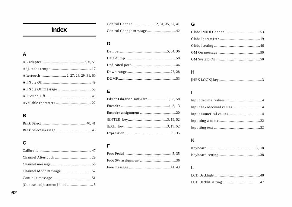
6
GGlobal MIDI Channel......................................53
Global parameter.............................................19
Global setting ...................................................46
GM On message...............................................50
GM System On.................................................50
H[HEX LOCK] key ...............................................3
IInput decimal values.........................................4
Input hexadecimal values ................................4
Input numerical values.....................................4
Inputting a name .............................................22
Inputting text ...................................................22
KKeyboard ......................................................2, 18
Keyboard setting .............................................38
LLCD Backlight..................................................48
LCD Backlit setting .........................................47
2
Index
AAC adapter............................................... 5, 6, 59
Adjust the tempo............................................. 17
Aftertouch ............................ 2, 27, 28, 29, 31, 60
All Note Off ..................................................... 49
All Note Off message ..................................... 50
All Sound Off................................................... 49
Available characters ....................................... 22
BBank Select ................................................. 40, 41
Bank Select message ....................................... 43
CCalibration ....................................................... 47
Channel Aftertouch ........................................ 29
Channel message ............................................ 56
Channel Mode message ................................. 57
Continue message........................................... 51
[Contrast adjustment] knob............................. 5
Control Change..........................2, 31, 35, 37, 41
Control Change message................................42
DDamper....................................................5, 34, 36
Data dump........................................................58
Dedicated port..................................................46
Down range ................................................27, 28
DUMP................................................................53
EEditor Librarian software .....................1, 53, 58
Encoder .....................................................1, 3, 13
Encoder assignment ........................................20
[ENTER] key...........................................3, 19, 52
[EXIT] key ...............................................3, 19, 52
Expression.....................................................5, 35
FFoot Pedal .....................................................5, 35
Foot SW assignment........................................36
Free message ..............................................41, 43

63
Pedal Calibration............................................. 47
PEDAL jack .................................................. 5, 16
Pedal operation................................................ 38
Pitch Bend .................................................... 2, 27
Pitch Bend assignment ................................... 26
Pitch bend wheel ............................... 1, 2, 15, 60
Play mode..................................................... 8, 13
Polarity setting........................................... 46, 47
Polyphonic key pressure................................ 29
Portamento............................................. 5, 34, 37
Portamento Time......................................... 5, 35
Power supply connector .................................. 5
Power switch...................................................... 5
PRELOAD ........................................................ 54
Preset scene ................................................ 52, 54
Preset Scene Name.......................................... 58
Program Change ............................. 2, 33, 40, 41
Program Change & Bank Select .................... 40
Program Change message ............................. 42
QQuick Assign.................................................... 11
Quick-assign for control changes.................. 23
LSB .....................................................................43
LSB/MSB ..........................................................57
MMain display.......................................................2
Main encoder................................................2, 17
Main Encoder assignment..............................40
Master Balance .............................................2, 27
Master Volume.............................................5, 35
[MESSAGE] key...........................................3, 49
Message mode..............................................8, 49
Message setting................................................41
MIDI Channel...................................................53
MIDI Clock .............................................2, 17, 60
MIDI connection ................................................6
MIDI connector ..................................................5
MIDI Control Change messages....................56
MIDI implementation .....................................58
MIDI IN connector ..........................................46
MIDI IN Port ....................................................46
MIDI OUT A connector ..................................46
MIDI OUT B connector...................................46
MIDI OUT B port.............................................46
MOD Wheel assignment ................................30
Modulation wheel .............................1, 2, 15, 60
Momentary...........................................14, 25, 38
Moving the cursor ...........................................22
MSB ...................................................................43
NNative Korg mode...........................................58
Note message ...............................................2, 25
Note No. ...........................................................57
NRPN ......................................1, 3, 20, 21, 23, 57
OOctave setting ..................................................18
OCTAVE SHIFT/CURSOR keys ........3, 19, 52
One-parameter.......................................2, 32, 33
PPAD 1–8 assignment .......................................24
PAD 9–16 assignment .....................................26
PAD Illumination setting .........................47, 48
Pad number ........................................................4
Pad operation...................................................25
PAD Type .........................................................25
Panic message ..................................................49
Panpot ...........................................................5, 35
Pedal assignment.............................................35

6
VVector joystick..........................................1, 2, 15
Vector-X assignment .......................................31
Vector-Y assignment .......................................32
Velocity .................................2, 27, 28, 29, 31, 60
Velocity Curve .................................................39
Velocity Sens ....................................................25
Velocity Type ...................................................25
Volume..........................................................5, 35
WWRITE...............................................................55
XX-axis .................................................................31
YY-axis .................................................................32
4
RReset All Controller ........................................ 49
RPN......................................... 1, 3, 20, 21, 23, 57
SSave ................................................................... 55
[SCENE] key ................................................ 3, 52
Scene MIDI Channel....................................... 53
Scene mode .................................................. 8, 52
Scene set ........................................................... 12
Select Scene ...................................................... 52
[SETTING] key .................................................. 3
Setting mode................................................ 8, 19
Slider ......................................................... 1, 3, 13
Slider assignment............................................ 24
Snapshot message ........................................... 50
Soft Pedal ............................................... 5, 34, 37
Sostenuto................................................ 5, 34, 37
START............................................................... 51
Start message ................................................... 51
STOP ................................................................. 50
Stop message ................................................... 50
Sub-display ........................................................ 3
SW1/SW2 assignment ................................... 32
Switch 1, Switch 2 ........................................2, 16
SWITCH jack ................................................5, 16
System Exclusive message .............................58
System Realtime message...............................56
TTap tempo message.........................................51
Tempo Change .................................................40
TEMPO LED.......................................................2
Toggle..............................................14, 25, 38, 60
Transmitted on the MIDI channel .................53
Trigger pad ...........................................1, 2, 4, 14
Two-parameter.......................................2, 32, 33
UUp range......................................................27, 28
USB connection ..................................................6
USB connector ....................................................5
USB-MIDI..........................................................45
USB-MIDI Port setting ....................................44
User memories ...................................................1
User message....................................................51


Ow
ner’s manual
2E
2004 KORG INC. 1610 GH Printed in Japan
4015-2 Yanokuchi, Inagi-city, Tokyo 206-0812 Japan
IMPORTANT NOTICE TO CONSUMERSThis product has been manufactured according to strict specifications and voltage requirementsthat are applicable in the country in which it is intended that this product should be used. If youhave purchased this product via the internet, through mail order, and/or via a telephone sale, youmust verify that this product is intended to be used in the country in which you reside.WARNING: Use of this product in any country other than that for which it is intendedcould be dangerous and could invalidate the manufacturer’s or distributor’s warranty.Please also retain your receipt as proof of purchase otherwise your product may bedisqualified from the manufacturer’s or distributor’s warranty.


