Komatsu D155AX Bulldozer Operation Maintenance Manual
279
https://tractormanualz.com
Transcript of Komatsu D155AX Bulldozer Operation Maintenance Manual

https://tractormanualz.com

1-1
FOREWORD11
https://tractormanualz.com

FOREWORD FOREWORD
1-2
FOREWORD
This manual provides rules and guidelines which will help you use this machine safely and effectively. The precau-tions in this manual must be followed at all times when performing operation and maintenance. Most accidents arecaused by the failure to follow fundamental safety rules for the operation and maintenance of machines. Accidentscan be prevented by knowing beforehand conditions that may cause hazard when performing operation and main-tenance.
WARNINGOperators and maintenance personnel must always do as follows before beginning operation or mainte-nance.
● Always be sure to read and understand this manual thoroughly before performing operation andmaintenance.
● Read the safety messages given in this manual and the safety labels affixed to the machine thor-oughly and be sure that you understand them fully.
Keep this manual at the storage location for the Operation and Maintenance Manual given below, andhave all personnel read it periodically.
If this manual has been lost or has become dirty and cannot be read, request a replacement manualimmediately from Komatsu or your Komatsu distributor.
If you sell the machine, be sure to give this manual to the new owners together with the machine.
Komatsu delivers machines that comply with all applicable regulations and standards of the country towhich it has been shipped. If this machine has been purchased in another country or purchased fromsomeone in another country, it may lack certain safety devices and speciffications that are necessary foruse in your country. If there is any question about whether your product complies with the applicablestandards and regulations of your country, consult Komatsu or your Komatsu distributor before operat-ing the machine.
Storage location for the Operation and Maintenance Manual:
Machine equipped with cab
Inside of right and left doors
Machine without cab
Back pocket of operator's seat
https://tractormanualz.com

FOREWORD FOREWORD
1-3https://tractormanualz.com

FOREWORD FOREWORD
1-4 https://tractormanualz.com

FOREWORD SAFETY INFORMATION
1-5
SAFETY INFORMATION
To enable you to use this machine safely, safety precautions and labels are given in this manual and affixed to themachine to give explanations of situations involving potential hazards and of the methods of avoiding such situa-tions.
Signal wordsThe following signal words are used to inform you that there is a potential hazardous situation that may lead to per-sonal injury or damage.
In this manual and on machine labels, the following signal words are used to express the potential level of hazard.
Indicates an imminently hazardous situation which, if not avoided, will result in death or seri-ous injury. This signal word is to be limited to most extreme situations.
Indicates a potentially hazardous situation which, if not avoided, could result in death orserious injury.
Indicates a potentially hazardous situation which, if not avoided, may result in minor or mod-erate injury. It may also be used to alert against unsafe practices.
Example of safety message using signal word
WARNINGTo avoid hitting unlocked operation levers, lower equipment to ground and move SAFETY LOCK LEVER(located near seat) to LOCK position before starting up from operator's seat.Sudden and unwanted machine movement can cause serious injury or death.
Other signal wordsIn addition to the above, the following signal words are used to indicate precautions that should be followed to pro-tect the machine or to give information that is are useful to know.
This word is used for precautions that must be taken to avoid actions which could shortenthe life of the machine.
This gives information that is useful to know.
DANGER
WARNING
CAUTION
NOTICE
REMARKS
https://tractormanualz.com

SAFETY INFORMATION FOREWORD
1-6
Safety labelsSafety labels are affixed to the machine to inform the operator or maintenance worker on the spot when carryingout operation or maintenance of the machine that may involve hazard.
This machine uses "Safety labels using words" and "Safety labels using pictograms" to indicate safety procedures.
Example of safety label using words
Safety labels using pictogramSafety pictograms use a picture to express a level of hazard-ous condition equivalent to the signal word. These safety picto-grams use pictures in order to let the operator or maintenanceworker understand the level and type of hazardous condition atall times. Safety pictograms show the type of hazardous condi-tion at the top or left side, and the method of avoiding the haz-ardous condition at the bottom or right side. In addition, thetype of hazardous condition is displayed inside a triangle andthe method of avoiding the hazardous condition is showninside a circle.
Komatsu cannot predict every circumstance that might involve a potential hazard in operation and maintenance.Therefore, the safety messages in this manual and on the machine may not include all possible safety precau-tions. If any procedures or actions not specifically recommended or allowed in this manual are used, it is yourresponsibility to take the necessary steps to ensure safety.
In no event should you engage in prohibited uses or actions described in this manual.
The explanations, values, and illustrations in this manual were prepared based on the latest information availableat that time. Continuing improvements in the design of this machine can lead to changes in detail which may notbe reflected in this manual. Consult Komatsu or your Komatsu distributor for the latest available information of yourmachine or for questions regarding information in this manual.
The numbers in circles in the illustrations correspond to the numbers in ( ) in the text. (For example: → (1))
Part No.
Part No.
https://tractormanualz.com
FOREWORD INTRODUCTION
1-7
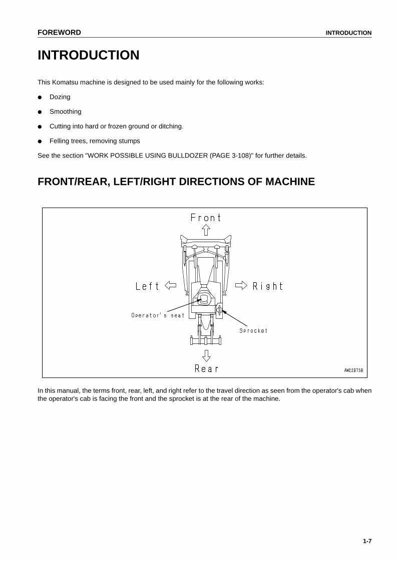
INTRODUCTION
This Komatsu machine is designed to be used mainly for the following works:
● Dozing
● Smoothing
● Cutting into hard or frozen ground or ditching.
● Felling trees, removing stumps
See the section "WORK POSSIBLE USING BULLDOZER (PAGE 3-108)" for further details.
FRONT/REAR, LEFT/RIGHT DIRECTIONS OF MACHINE
In this manual, the terms front, rear, left, and right refer to the travel direction as seen from the operator's cab whenthe operator's cab is facing the front and the sprocket is at the rear of the machine.
https://tractormanualz.com

NECESSARY INFORMATION FOREWORD
1-8
NECESSARY INFORMATION
When requesting service or ordering replacement parts, please inform your Komatsu distributor of the followingitems.
MACHINE SERIAL NO. PLATE AND POSITION
Under the front of the console box on the right side of the operator's seat.
ENGINE SERIAL NO. PLATE AND POSITION
On the upper of the engine starting motor on the right side of the machine.
https://tractormanualz.com
FOREWORD NECESSARY INFORMATION
1-9
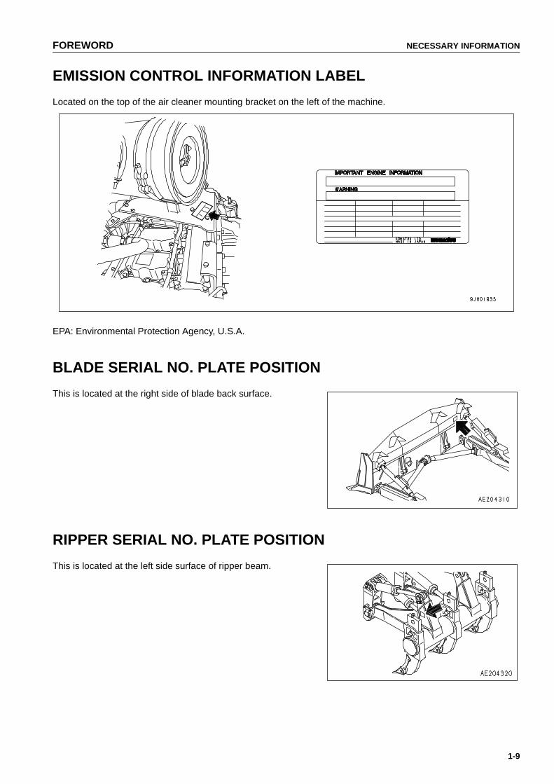
EMISSION CONTROL INFORMATION LABEL
Located on the top of the air cleaner mounting bracket on the left of the machine.
EPA: Environmental Protection Agency, U.S.A.
BLADE SERIAL NO. PLATE POSITION
This is located at the right side of blade back surface.
RIPPER SERIAL NO. PLATE POSITION
This is located at the left side surface of ripper beam.
https://tractormanualz.com
NECESSARY INFORMATION FOREWORD
1-10
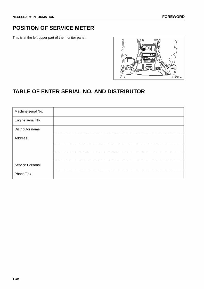
POSITION OF SERVICE METER
This is at the left upper part of the monitor panel.
TABLE OF ENTER SERIAL NO. AND DISTRIBUTOR
Machine serial No.
Engine serial No.
Distributor name
Address
Service Personal
Phone/Fax
https://tractormanualz.com

FOREWORD CONTENTS
1-11
CONTENTS
FOREWORD
FOREWORD......................................................................................................................................................... 1-2
SAFETY INFORMATION...................................................................................................................................... 1-5
INTRODUCTION................................................................................................................................................... 1-7
FRONT/REAR, LEFT/RIGHT DIRECTIONS OF MACHINE....................................................................... 1-7
NECESSARY INFORMATION ............................................................................................................................. 1-8
MACHINE SERIAL NO. PLATE AND POSITION....................................................................................... 1-8
ENGINE SERIAL NO. PLATE AND POSITION.......................................................................................... 1-8
EMISSION CONTROL INFORMATION LABEL ......................................................................................... 1-9
BLADE SERIAL NO. PLATE POSITION .................................................................................................... 1-9
RIPPER SERIAL NO. PLATE POSITION................................................................................................... 1-9
POSITION OF SERVICE METER ............................................................................................................ 1-10
TABLE OF ENTER SERIAL NO. AND DISTRIBUTOR ............................................................................ 1-10
SAFETY
SAFETY ................................................................................................................................................................ 2-2
SAFETY LABELS................................................................................................................................................. 2-4
POSITIONS OF SAFETY PICTOGRAMS .................................................................................................. 2-5
SAFETY LABELS ....................................................................................................................................... 2-6
GENERAL PRECAUTIONS ............................................................................................................................... 2-10
PRECAUTIONS FOR OPERATION ................................................................................................................... 2-19
STARTING ENGINE................................................................................................................................. 2-19
OPERATION............................................................................................................................................. 2-21
TRANSPORTATION................................................................................................................................. 2-25
BATTERY ................................................................................................................................................. 2-26
TOWING ................................................................................................................................................... 2-28
PRECAUTIONS FOR MAINTENENCE .............................................................................................................. 2-29
OPERATION
GENERAL VIEW .................................................................................................................................................. 3-2
GENERAL VIEW OF MACHINE................................................................................................................. 3-2
GENERAL VIEW OF CONTROLS AND GAUGES..................................................................................... 3-3
https://tractormanualz.com

CONTENTS FOREWORD
1-12
EXPLANATION OF COMPONENTS.................................................................................................................... 3-6
FRONT PANEL........................................................................................................................................... 3-7
SWITCHES ............................................................................................................................................... 3-24
CONTROL LEVERS, PEDALS, DIAL ....................................................................................................... 3-28
DUST INDICATOR ................................................................................................................................... 3-35
POWER SOURCE .................................................................................................................................... 3-35
FUSE BOX................................................................................................................................................ 3-36
DOOR-OPEN LOCK ................................................................................................................................. 3-38
SASH GLASS INTERMEDIATE LOCK..................................................................................................... 3-38
HOT AND COOL BOX .............................................................................................................................. 3-39
DOOR POCKET ....................................................................................................................................... 3-39
ASHTRAY ................................................................................................................................................. 3-39
TOOL BOX................................................................................................................................................ 3-40
USING CAR RADIO.................................................................................................................................. 3-41
AM/FM RADIO .......................................................................................................................................... 3-46
HANDLING AIR CONDITIONER .............................................................................................................. 3-54
HANDLING HEATER................................................................................................................................ 3-58
HANDLING ACCUMULATOR................................................................................................................... 3-59
OPERATION ....................................................................................................................................................... 3-60
CHECK BEFORE STARTING ENGINE.................................................................................................... 3-60
STARTING ENGINE ................................................................................................................................. 3-79
AFTER STARTING ENGINE .................................................................................................................... 3-85
WARMING-UP OPERATION.................................................................................................................... 3-86
STOPPING ENGINE................................................................................................................................. 3-90
CHECK AFTER STOPPING ENGINE ...................................................................................................... 3-91
MACHINE OPERATION ........................................................................................................................... 3-92
STEERING MACHINE .............................................................................................................................. 3-98
PRECAUTIONS FOR OPERATION ....................................................................................................... 3-101
PARKING MACHINE .............................................................................................................................. 3-103
CHECK AFTER FINISHING WORK ....................................................................................................... 3-105
LOCKING................................................................................................................................................ 3-105
RIPPER OPERATION ............................................................................................................................ 3-106
WORK POSSIBLE USING BULLDOZER ............................................................................................... 3-108
ADJUSTING POSTURE OF WORK EQUIPMENT................................................................................. 3-110
TIPS FOR LONGER UNDERCARRIAGE LIFE ...................................................................................... 3-117
TRANSPORTATION......................................................................................................................................... 3-120
LOADING, UNLOADING WORK ............................................................................................................ 3-120
PRECAUTIONS FOR LOADING ............................................................................................................ 3-120
METHOD OF LIFTING MACHINE .......................................................................................................... 3-121
PRECAUTIONS FOR TRANSPORTATION ........................................................................................... 3-122
REMOVAL OF CAB ................................................................................................................................ 3-123
COLD WEATHER OPERATION ...................................................................................................................... 3-125
COLD WEATHER OPERATION INFORMATION................................................................................... 3-125
AFTER DAILY WORK COMPLETION.................................................................................................... 3-127
AFTER COLD WEATHER SEASON ...................................................................................................... 3-127
https://tractormanualz.com
FOREWORD CONTENTS
1-13
LONG TERM STORAGE.................................................................................................................................. 3-128
BEFORE STORAGE............................................................................................................................... 3-128
DURING STORAGE ............................................................................................................................... 3-128
AFTER STORAGE.................................................................................................................................. 3-128
TROUBLESHOOTING...................................................................................................................................... 3-129
AFTER RUNNING OUT OF FUEL.......................................................................................................... 3-129
METHOD OF TOWING MACHINE......................................................................................................... 3-130
DISCHARGED BATTERY ...................................................................................................................... 3-131
OTHER TROUBLE ................................................................................................................................. 3-135
MAINTENANCE
GUIDE TO MAINTENANCE ................................................................................................................................. 4-2
OUTLINE OF SERVICE........................................................................................................................................ 4-5
OUTLINE OF OIL, FUEL, COOLANT......................................................................................................... 4-5
ELECTRIC SYSTEM MAINTENANCE ....................................................................................................... 4-8
WEAR PARTS ...................................................................................................................................................... 4-9
WEAR PARTS LIST.................................................................................................................................... 4-9
USE OF FUEL, COOLANT AND LUBRICANTS ACCORDING TO AMBIENT TEMPERATURE .................... 4-11
PROPER SELECTION OF FUEL, COOLANT AND LUBRICANTS ......................................................... 4-11
STANDARD TIGHTENING TORQUES FOR BOLTS AND NUTS..................................................................... 4-15
TORQUE LIST.......................................................................................................................................... 4-15
PERIODIC REPLACEMENT OF SAFETY CRITICAL PARTS .......................................................................... 4-16
SAFETY CRITICAL PARTS...................................................................................................................... 4-17
MAINTENANCE SCHEDURE CHART............................................................................................................... 4-19
MAINTENANCE SCHEDURE CHART ..................................................................................................... 4-19
SERVICE PROCEDURE .................................................................................................................................... 4-21
INITIAL 250 HOURS MAINTENANCE...................................................................................................... 4-21
WHEN REQUIRED................................................................................................................................... 4-22
CHECK BEFORE STARTING .................................................................................................................. 4-43
EVERY 250 HOURS SERVICE................................................................................................................ 4-44
EVERY 500 HOURS SERVICE................................................................................................................ 4-51
EVERY 1000 HOURS SERVICE.............................................................................................................. 4-57
EVERY 2000 HOURS SERVICE.............................................................................................................. 4-65
EVERY 4000 HOURS SERVICE.............................................................................................................. 4-69
EVERY 8000 HOURS SERVICE.............................................................................................................. 4-72
SPECIFICATIONS
SPECIFICATIONS ................................................................................................................................................ 5-2
https://tractormanualz.com

CONTENTS FOREWORD
1-14
ATTACHMENTS AND OPTIONS
GENERAL PRECAUTIONS ................................................................................................................................. 6-2
PRECAUTIONS RELATED TO SAFETY ................................................................................................... 6-2
INTRODUCTION OF OPTIONAL PARTS AND ATTACHMENTS....................................................................... 6-4
INTRODUCTION OF OPTIONAL PARTS AND ATTACHMENTS.............................................................. 6-4
HANDLING HEADREST ...................................................................................................................................... 6-5
HANDLING REVERSIBLE FAN ........................................................................................................................... 6-6
REVERSING REVERSIBLE FAN ............................................................................................................... 6-6
HANDLING CAP WITH LOCK ............................................................................................................................. 6-7
OPENING AND CLOSING LOCKABLE CAP ............................................................................................. 6-7
PROCEDURE FOR SELECTING RIPPER POINT............................................................................................... 6-8
PROCEDURE FOR SELECTING RIPPER POINT..................................................................................... 6-8
INDEX ................................................................................................................................................................... 7-1
https://tractormanualz.com

2-1
SAFETY21
WARNINGPlease read and make sure that you fully understand theprecautions described in this manual and the safety labelson the machine. When operating or servicing the machine,always follow these precaustions strictly.
https://tractormanualz.com

SAFETY SAFETY
2-2
SAFETY
SAFETY LABELS.................................................................................................................................................. 2-4
POSITIONS OF SAFETY PICTOGRAMS ....................................................................................................... 2-5
SAFETY LABELS............................................................................................................................................. 2-6
GENERAL PRECAUTIONS ................................................................................................................................ 2-10
SAFETY RULES ....................................................................................................................................... 2-10IF ABNORMALITIES ARE FOUND .......................................................................................................... 2-10CLOTHING AND PERSONAL PROTECTIVE ITEMS .............................................................................. 2-10FIRE EXTINGUISHER AND FIRST AID KIT ............................................................................................ 2-10SAFETY FEATURES................................................................................................................................ 2-11KEEP MACHINE CLEAN.......................................................................................................................... 2-11INSIDE OPERATOR'S COMPARTMENT................................................................................................. 2-11ALWAYS APPLY LOCK WHEN LEAVING OPERATOR'S SEAT ............................................................ 2-11HANDRAILS AND STEPS ........................................................................................................................ 2-12MOUNTING AND DISMOUNTING ........................................................................................................... 2-13NO PEOPLE ON ATTACHMENTS........................................................................................................... 2-13PREVENTION OF BURNS ....................................................................................................................... 2-14FIRE PREVENTION ................................................................................................................................. 2-14ACTION IF FIRE OCCURS ...................................................................................................................... 2-15WINDOW WASHER LIQUID .................................................................................................................... 2-15PRECAUTIONS WHEN USING ROPS .................................................................................................... 2-15PRECAUTIONS FOR ATTACHMENTS ................................................................................................... 2-16UNAUTHORIZED MODIFICATION .......................................................................................................... 2-16SAFETY AT WORKSITE .......................................................................................................................... 2-16WORKING ON LOOSE GROUND............................................................................................................ 2-17DO NOT GO CLOSE TO HIGH-VOLTAGE CABLES............................................................................... 2-17ENSURE GOOD VISIBILITY .................................................................................................................... 2-17VENTILATION FOR ENCLOSED AREAS................................................................................................ 2-18CHECKING SIGNALMAN'S SIGNALS AND SIGNS ................................................................................ 2-18BE CAREFUL ABOUT ASBESTOS DUST............................................................................................... 2-18
https://tractormanualz.com

SAFETY SAFETY
2-3
PRECAUTIONS FOR OPERATION ................................................................................................................... 2-19
STARTING ENGINE ...................................................................................................................................... 2-19
CHECKS BEFORE STARTING ENGINE ................................................................................................. 2-19PRECAUTIONS WHEN STARTING......................................................................................................... 2-20PRECAUTIONS IN COLD AREAS ........................................................................................................... 2-20
OPERATION.................................................................................................................................................. 2-21
CHECKS AFTER OPERATION................................................................................................................ 2-21PRECAUTIONS FOR MOVING MACHINE FORWARD OR IN REVERSE ............................................. 2-21PRECAUTIONS WHEN TRAVELING....................................................................................................... 2-22TRAVELING ON SLOPES........................................................................................................................ 2-23PROHIBITION OF DANGEROUS WORK ................................................................................................ 2-23USING BRAKES....................................................................................................................................... 2-23OPERATE CAREFULLY ON SNOW........................................................................................................ 2-23PARKING MACHINE ................................................................................................................................ 2-24
TRANSPORTATION...................................................................................................................................... 2-25
LOADING AND UNLOADING................................................................................................................... 2-25SHIPPING................................................................................................................................................. 2-25
BATTERY ...................................................................................................................................................... 2-26
BATTERY HAZARD PREVENTION ......................................................................................................... 2-26STARTING WITH BOOSTER CABLE ...................................................................................................... 2-27
TOWING ........................................................................................................................................................ 2-28
WHEN TOWING ....................................................................................................................................... 2-28
PRECAUTIONS FOR MAINTENENCE .............................................................................................................. 2-29
WARNING TAG ........................................................................................................................................ 2-29KEEP WORK PLACE CLEAN AND TIDY................................................................................................. 2-29APPOINT LEADER WHEN WORKING WITH OTHERS.......................................................................... 2-29STOP ENGINE BEFORE CARRYING OUT INSPECTION AND MAINTENANCE .................................. 2-30TWO WORKERS FOR MAINTENANCE WHEN ENGINE IS RUNNING ................................................. 2-30PROPER TOOLS...................................................................................................................................... 2-31HANDLING ACCUMULATOR................................................................................................................... 2-31NO UNAUTHORIZED PERSONNEL INTO AREA ................................................................................... 2-31ATTACHMENTS....................................................................................................................................... 2-32PRECAUTIONS FOR WORK UNDER MACHINE AND WORK EQUIPMENT......................................... 2-32NOISE....................................................................................................................................................... 2-32PRECAUTIONS WHEN USING HAMMER............................................................................................... 2-32REPAIR WELDING................................................................................................................................... 2-33REMOVING BATTERY TERMINAL.......................................................................................................... 2-33PRECAUTIONS WHEN USING HIGH-PRESSURE GREASE TO ADJUST TRACK TENSION ............. 2-33DO NOT DISASSEMBLE RECOIL SPRING ............................................................................................ 2-33PRECAUTION WITH HIGH-PRESSURE OIL .......................................................................................... 2-34PRECAUTIONS WITH PRESSURIZED FUEL......................................................................................... 2-34HANDLING HIGH-PRESSURE HOSES................................................................................................... 2-34PRECAUTIONS WITH HIGH VOLTAGE.................................................................................................. 2-34WASTE MATERIAL .................................................................................................................................. 2-35MAINTENANCE FOR AIR CONDITIONER.............................................................................................. 2-35COMPRESSED AIR ................................................................................................................................. 2-35PERIODIC REPLACEMENT OF SAFETY CRITICAL PARTS ................................................................. 2-35
https://tractormanualz.com

SAFETY LABELS SAFETY
2-4
SAFETY LABELS
The following warning signes and safety labels are used on this machine.
● Be sure that you fully understand the correct position and content of labels.
● To ensure that the content of labels can be read properly. Be sure that they are in the correct place and alwayskeep them clean. When cleaning them, do not use organic solvents or gasoline, there may cause the labels topeel off.
● There are also other labels in addition to the warning signes and safety labels. Handle those labels in thesame way.
● If the labels are damaged, lost, or cannot be read properly, replace them with new ones. For details of the partnumbers for the labels, see this manual or the actual label, and place an order with Komatsu distributor.
https://tractormanualz.com

SAFETY SAFETY LABELS
2-5
POSITIONS OF SAFETY PICTOGRAMS
https://tractormanualz.com

SAFETY LABELS SAFETY
2-6
SAFETY LABELS
(1) Precautions for operation, inspection and mainte-nance (09651-A06411)
(2) Precautions when traveling in reverse (09802-B0750)
(3) Precautions for leaving the operator's seat (09654-B0641)
(4) Precautions for high-temperature hydraulic oil (09653-A0481)
https://tractormanualz.com

SAFETY SAFETY LABELS
2-7
(5) Precautions for check and adjust track tension (09657-A0881)
Safety label is attached on the back side of the inspection cover of the track frame.
(6) Precautions for handling accumulator(09659-A057B)
(7) Precautions for use of seat belt(195-98-12940)
(8) Warning for ROPS (09620-30200)
https://tractormanualz.com

SAFETY LABELS SAFETY
2-8
(9) Precautions for handling electric wires (09808-A0881)
(10) Precautions for avoiding falling down (09805-C0881)
(11) Caution for engine running (09667-A0481)
(12) Caution for approach when machine moving (09806-B1201)
https://tractormanualz.com

SAFETY SAFETY LABELS
2-9
(13) Precautions for high voltage(7872-10-1600)
https://tractormanualz.com

GENERAL PRECAUTIONS SAFETY
2-10
GENERAL PRECAUTIONS
SAFETY RULES
● Only trained and authorized personnel can operate and maintain the machine.
● Follow all safety rules, precautions and instructions when operating or performing maintenance on themachine.
● If you are under the influence of alcohol or medication, your ability to safely operate or repair your machinemay be severly impaired putting yourself and everyone else on your jobsite in danger.
● When working with another operator or with a person on worksite traffic duty, be sure that all personnel under-stand all hand signals that are to be used.
IF ABNORMALITIES ARE FOUND
If you find any abnormality in the machine during operation or maintenance (noise, vibration, smell, incorrectgauges, smoke, oil leakage, etc., or any abnormal display on the warning devices or monitor), report to the personin charge and have the necessary action taken. Do not operate the machine until the abnormality has been cor-rected.
CLOTHING AND PERSONAL PROTECTIVE ITEMS
● Do not wear loose clothing and accessories. There is ahazard that they may catch on control levers or other pro-truding parts.
● If you have long hair and it hangs out from your hard hat,there is a hazard that it may get caught up in the machine,so tie your hair up and be careful not to let it get caught.
● Always wear a hard hat and safety shoes. If the nature ofthe work requires it, wear safety glasses, mask, gloves, earplugs, and safety belt when operating or maintaining themachine.
● Check that all protective equipment functions properly before using it.
FIRE EXTINGUISHER AND FIRST AID KIT
Always follow the precautions below to prepare for action if any injury or fire should occur.
● Be sure that fire extinguishers have been provided andread the labels to ensure that you know how to use them inemergencies.
● Carry out periodic inspection and maintenance to ensurethat the fire extinguisher can always be used.
● Provide a first aid kit at the storage point. Carry out periodicchecks and add to the contents if necessary.
https://tractormanualz.com

SAFETY GENERAL PRECAUTIONS
2-11
SAFETY FEATURES
● Be sure that all guards and covers are in their proper position. Have guards and covers repaired immediatelyif they are damaged.
● Understand the method of use of safety features and use them properly.
● Never remove any safety features. Always keep them in good operating condition.
KEEP MACHINE CLEAN
● If water gets into the electrical system, there is a hazardthat it will cause malfunctions or misoperation. Do not usewater or steam to wash the electrical system (sensors,connectors).
● If inspection and maintenance is carried out when themachine is still dirty with mud or oil, there is a hazard thatyou will slip and fall, or that dirt or mud will get into youreyes. Always keep the machine clean.
INSIDE OPERATOR'S COMPARTMENT
● When entering the operator's compartment, always remove all mud and oil from the soles of your shoes. If youoperate the pedal with mud or oil affixed to your shoes, your foot may slip and this may cause a serious acci-dent.
● Do not leave parts or tools lying around the operator's compartment.
● Do not stick suction pads to the window glass. Suction pads act as a lens and may cause fire.
● Do not use cellular telephones inside the operator's compartment when driving or operating the machine.
● Never bring any dangerous objects such as flammable or explosive items into the operator's cab.
ALWAYS APPLY LOCK WHEN LEAVING OPERATOR'S SEAT
● Before standing up from the operator's seat (such as whenadjusting the operator's seat), lower the work equipmentcompletely to the ground, set safety lock lever and brakelock lever securely to the LOCK position, then stop theengine. If you accidentally touch the levers when they are notlocked, there is a hazard that the machine may suddenlymove and cause serious injury or property damage.
https://tractormanualz.com

GENERAL PRECAUTIONS SAFETY
2-12
● When leaving the machine, always lower the work equip-ment completely to the ground, set safety lock lever andbrake lock lever securely to the LOCK position, then stopthe engine. Use the key to lock all the equipment. Alwaysremove the key, take it with you, and keep it in the specifiedplace.
HANDRAILS AND STEPS
To prevent personal injury caused by slipping or falling off the machine, always do as follows.
● Use the parts marked by arrow A in the diagram belowwhen getting on or off machine.Never use the parts marked by arrow B when getting on oroff the machine.Use them only when moving along the top of the track orwhen checking or carrying out maintenance inside the sidecover,or when filling the tank with oil.
● Never hold any control levers or lock levers when gettingon or off the machine.
● To ensure safety, always face the machine and maintainthree-point contact (both feet and one hand, or both handsand one foot) with the handrails and steps (including thetrack shoe) to ensure that you support yourself.
● Do not grip the control levers when getting on or off themachine.
● Never climb on the engine hood or covers where there areno non-slip pads.
● Before getting on or off the machine, check the handrails and steps (including the track shoe). If there is anyoil, grease, or mud on the handrails or steps (including the track shoe), wipe it off immediately. Always keepthese parts clean. Repair any damage and tighten any loose bolts.
● Do not get on or off the machine while holding tools in your hand.
https://tractormanualz.com

SAFETY GENERAL PRECAUTIONS
2-13
MOUNTING AND DISMOUNTING
● Never jump on or off the machine. Never get on or off a moving machine.
● If the machine starts to move when there is no operator on the machine, do not jump on to the machine and tryto stop it.
NO PEOPLE ON ATTACHMENTS
Never let anyone ride on the attachments. There is a hazard of falling and suffering serious injury.
https://tractormanualz.com

GENERAL PRECAUTIONS SAFETY
2-14
PREVENTION OF BURNS
Hot coolant● To prevent burns from hot water or steam spurting out
when checking or draining the coolant, wait for the water tocool to a temperature where it is possible to touch the radi-ator cap by hand before starting the operation. Even whenthe coolant has cooled down, loosen the cap slowly torelieve the pressure inside the radiator before removing thecap.
Hot oil● To prevent burns from hot oil or other parts when checking
or draining the oil, wait for the oil to cool to a temperaturewhere it is possible to touch the cap by hand before start-ing the operation. Even when the oil has cooled down,loosen the plug slowly to relieve the internal pressurebefore removing the plug.
FIRE PREVENTION
● Fire caused by fuel or oilFuel, oil, antifreeze, and window washer liquid are particu-larly flammable and can be hazardous. To prevent fire,always observe the following:
● Do not smoke or use any flame near fuel or oil.
● Stop the engine before refueling.
● Do not leave the machine while adding fuel or oil.
● Tighten all fuel and oil caps securely.
● Do not spill fuel on overheated surfaces or on parts ofthe electrical system.
● Use well-ventilated areas for adding or storing oil andfuel.
● Keep oil and fuel in the determined place and do notallow unauthorized persons to enter.
● After adding fuel or oil, wipe up any spilled fuel or oil.
● When carrying out grinding or welding work on thechassis, move any flammable materials to a safe placebefore starting.
● When washing parts with oil, use a non-flammable oil. Diesel oil and gasoline may catch fire, so do notuse them.
● Put greasy rags and other flammable materials into a safe container to maintain safety at the work place.
https://tractormanualz.com

SAFETY GENERAL PRECAUTIONS
2-15
● Do not weld or use a cutting torch to cut any pipes or tubes that contain flammable liquids.
● Fire caused by accumulation of flammable material.● Remove any dry leaves, chips, pieces of paper, dust, or any other flammable materials accumulated or
affixed around the engine, exhaust manifold, muffler, or battery, or inside the undercovers.
● Fire coming from electric wiringShort circuits in the electrical system can cause fire.
● Always keep electric wiring connections clean and securely tightened.
● Check the wiring every day for looseness or damage. Tighten any loose connectors or wiring clamps.Repair or replace any damaged wiring.
● Fire coming from hydraulic lineCheck that all the hose and tube clamps, guards, and cushions are securely fixed in position. If they are loose,they may vibrate during operation and rub against other parts. This may lead to damage to the hoses, andcause high-pressure oil to spurt out, leading to fire damage or serious injury.
● Explosion caused by lighting equipment● When checking fuel, oil, battery electrolyte, window washer fluid, or coolant, use explosion-proof lighting.
If you do not use explosion-proof lighting, there is a hazard of serious injury or damage caused by explo-sion.
● When taking the electrical power for the lighting from the machine, follow the instructions in this manual.
ACTION IF FIRE OCCURS
If a fire occurs, escape from the machine as follows.
● Turn the starting switch OFF and stop the engine.
● Use the handrails and steps to get off the machine.
WINDOW WASHER LIQUID
Use an ethyl alcohol base washer liquid. Methyl alcohol base washer liquid may irritate your eyes, so do not use it.
PRECAUTIONS WHEN USING ROPS
Install ROPS when working in places where there is danger offalling rocks, such as in mines and quarries, or in places wherethere is danger of rolling over.
● If ROPS is installed, do not remove it when operating themachine.
● ROPS is installed to protect the operator when machinerolls over. When machine rolls over, ROPS supports itsweight and absorbs its impact energy.
● If ROPS is modified, its strength may lower. When modify-ing it, consult your Komatsu distributor.
● If ROPS is deformed by falling objects or by rolling over, its strength lowers and its design functions cannot bemaintained. In this case, be sure to ask your Komatsu distributor about repair method.
https://tractormanualz.com
GENERAL PRECAUTIONS SAFETY
2-16
● Even if ROPS is installed, it does not work normally, if your seat belt is not fastened. Be sure to fasten yourseat belt when operating machine.
PRECAUTIONS FOR ATTACHMENTS
● When installing optional parts or attachments, there may be problems with safety or legal restrictions, soplease contact your Komatsu distributor for advice.
● Any injuries, accidents, or product failures resulting from the use of unauthorized attachments or parts will notbe the responsibility of Komatsu.
● When installing and using optional attachments, read the instruction manual for the attachment, and the gen-eral information related to attachments in this manual.
UNAUTHORIZED MODIFICATION
Any modification mode without authorization from Komatsu can create hazards. Before making a modification,consult your Komatsu distributor.
● Komatsu will not be responsible for any injuries, accidents, or product failures resulting from modificationsmade without authorization from Komatsu.
SAFETY AT WORKSITE
Before starting operations, thoroughly check the area for any unusual conditions that could be dangerous.
● When carrying out operations near combustable materials such as thatched roofs, dry leaves or dry grass,there is a hazard of fire, so be careful when operating.
● Check the terrain and condition of the ground at the worksite, and determine the safest method of operation.Do not carry out operations at places where there is a hazard of landslides or falling rocks.
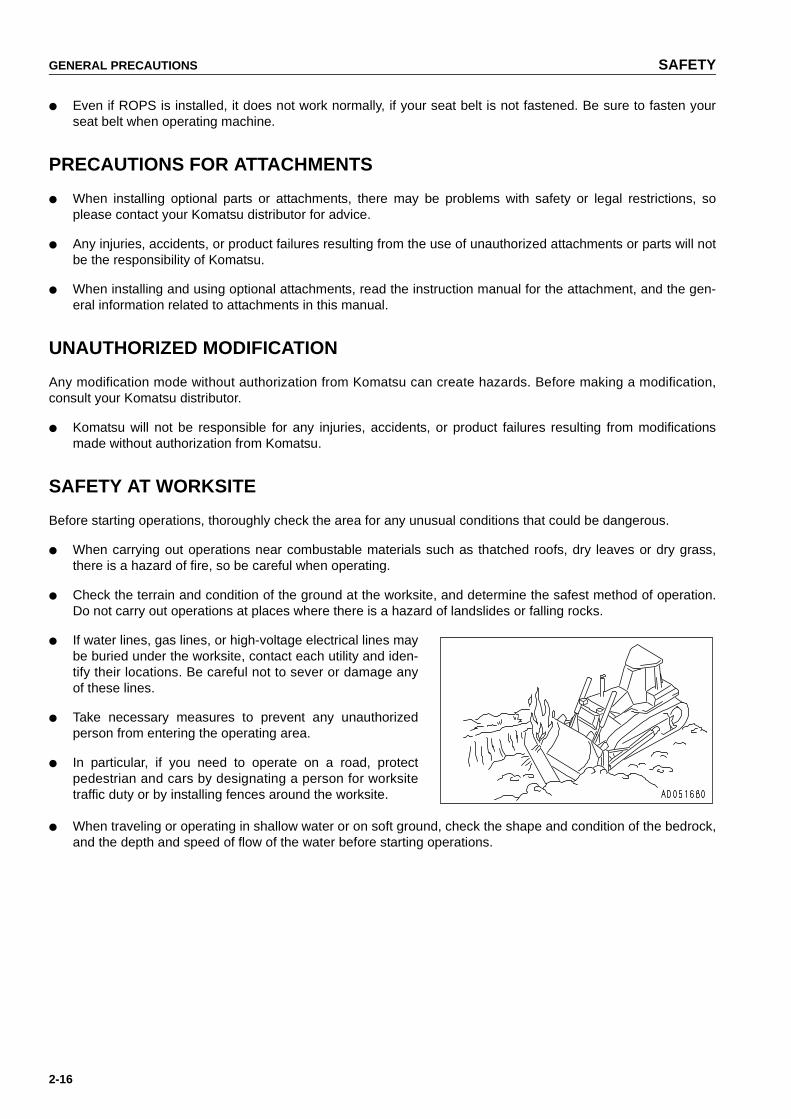
● If water lines, gas lines, or high-voltage electrical lines maybe buried under the worksite, contact each utility and iden-tify their locations. Be careful not to sever or damage anyof these lines.
● Take necessary measures to prevent any unauthorizedperson from entering the operating area.
● In particular, if you need to operate on a road, protectpedestrian and cars by designating a person for worksitetraffic duty or by installing fences around the worksite.
● When traveling or operating in shallow water or on soft ground, check the shape and condition of the bedrock,and the depth and speed of flow of the water before starting operations.
https://tractormanualz.com

SAFETY GENERAL PRECAUTIONS
2-17
WORKING ON LOOSE GROUND
● Avoid traveling or operating your machine too close to the edge of cliffs, overhangs, and deep ditches. Theground may be weak in such areas. If the ground should collapse under the weight or vibration of the machine,there is a hazard that the machine may fall or tip over. Remember that the soil after heavy rain or blasting orafter earthquakes is weak in these areas.
● When working on embankments or near excavated ditches, there is a hazard that the weight and vibration ofthe machine will cause the soil to collapse. Before starting operations, take steps to ensure that the ground issafe and to prevent the machine from rolling over or falling.
DO NOT GO CLOSE TO HIGH-VOLTAGE CABLES
Do not travel or operate the machine near electric cables. There is a hazard of electric shock, which may causeserious injury or property damage. On jobsites where the machine may go close to electric cables, always do asfollows.
● Before starting work near electric cables, inform the local power company of the work to be performed, andask them to take the necessary action.
● Even going close to high-voltage cables can cause electricshock, which may cause serious burns or even death.Always maintain a safe distance (see the table onthe right)between the machine and the electric cable. Check withthe local power company about safe operating procedurebefore starting operations.
● To prepare for any possible emergencies, wear rubbershoes and gloves. Lay a rubber sheet on top of the seat,and be careful not to touch the chassis with any exposedpart of your body.
● Use a signalman to give warning if the machineapproaches too close to the electric cables.
● When carrying out operations near high voltage cables, donot let anyone come close to the machine.
● If the machine should come too close or touch the electriccable, to prevent electric shock, the operator should notleave the operator's compartment until it has been con-firmed that the electricity has been shut off. Also, do not letanyone come close to the machine.
ENSURE GOOD VISIBILITY
Check for any persons or obstacles in the area around the machine and check the conditions of the jobsite toensure that operations and travel can be carried out safely. Always do as follows.
● Position a signalman if there are areas at the rear of the machine where the visibility is not good.
● When working in dark places, turn on the working lamp and front lamps installed to the machine, and setup additional lighting in the work area if necessary.
● Stop operations if the visibility is poor, such as in mist, snow, rain, or dust.
VoltageMin. safety
distance
Low voltage
100V 200V 2m
6,600V 2m
Very high voltage
22,000V 3m
66,000V 4m
154,000V 5m
187,000V 6m
275,000V 7m
500,000V 11m
https://tractormanualz.com

GENERAL PRECAUTIONS SAFETY
2-18
VENTILATION FOR ENCLOSED AREAS
Exhaust fumes from the engine can kill.
● If it is necessary to start the engine within an enclosedarea, or when handling fuel, flushing oil, or paint, open thedoors and windows to ensure that you provide adequateventilation is provided to prevent gas poisoning.
CHECKING SIGNALMAN'S SIGNALS AND SIGNS
● Set up signs to inform of road shoulders and soft ground. If the visibility is not good, position a signalman ifnecessary. Operators should pay careful attention to the signs and follow the instructions from the signalman.
● Only one signalman should give signals.
● Make sure that all workers understand the meaning of all signals and signs before starting work.
BE CAREFUL ABOUT ASBESTOS DUST
Asbestos dust in the air can cause lung cancer if it is inhaled.There is danger of inhaling asbestos when working on jobsiteshandling demolition work or work handling industrial waste.Always observe the following.
● Spray water to keep down the dust when cleaning. Do notuse compressed air for cleaning.
● If there is danger that there may be asbestos dust in theair, always operate the machine from an upwind position.All workers should use an approved respirator.
● Do not allow other persons to approach during the operation.
● Always observe the rules and regulations for the work site and environmental standards.
This machine does not use asbestos, but there is a danger that imitation parts may contain asbestos, so alwaysuse genuine Komatsu parts.
https://tractormanualz.com

SAFETY PRECAUTIONS FOR OPERATION
2-19
PRECAUTIONS FOR OPERATION
STARTING ENGINE
If there is a warning tag hanging from the work equipment con-trol lever, do not start the engine or touch the levers.
CHECKS BEFORE STARTING ENGINE
Carry out the following checks before starting the engine at the beginning of the day's work.
● Completely remove all flammable materials accumulated around the engine and battery, and remove all dirtfrom the window glasses, mirrors, lights, hand rails, and steps.
● Check the coolant level, fuel level, and oil level in engine oil pan, check for clogging of the air cleaner, andcheck for damage to the electric wiring.
● Adjust the operator's seat to a position where it is easy to carry out operations, and check that there is no dam-age or wear to the seat belt or mounting clamps.
● Check that the gauges work properly, check the angle of the lights and working lamps, and check that the con-trol levers are all at the neutral position.
● Adjust the mirrors so that the rear of the machine can be seen clearly from the operator's seat.When adjusting, see "ADJUSTING MIRROR (PAGE 3-74)".
https://tractormanualz.com
PRECAUTIONS FOR OPERATION SAFETY
2-20
● Check that there are no persons or obstacles above, below, or in the area around the machine.
PRECAUTIONS WHEN STARTING
● When starting the engine, sound the horn as a warning.
● Start and operate the machine only while seated.
● Do not allow anyone apart from the operator to ride on the machine.
● Do not short circuit the starting motor circuit to start the engine. It is not only dangerous, but will also causedamage to the equipment.
PRECAUTIONS IN COLD AREAS
● Carry out the warming-up operation thoroughly. If the machine is not thoroughly warmed up before the controllevers are operated, the reaction of the machine will be slow, and this may lead to unexpected accidents.
● If the battery electrolyte is frozen, do not charge the battery or start the engine with a different power source.There is a hazard that this will ignite the battery.Before charging or starting the engine with a different power source, melt the battery electrolyte and check forfrost and leakage of battery electrolyte before starting.
https://tractormanualz.com

SAFETY PRECAUTIONS FOR OPERATION
2-21
OPERATION
CHECKS BEFORE OPERATION
When carrying out the checks, move the machine to a wide area where there are no obstructions, and operateslowly. Do not allow anyone near the machine.
● Always fasten your seat belt.
● Check the operation of travel, steering and brake systems,and work equipment control system.
● Check for any abnormality in the sound of the machine,vibration, heat, smell, or gauges; check also that there isno leakage of oil or fuel.
● If any abnormality is found, carry out repairs immediately.
PRECAUTIONS FOR MOVING MACHINE FORWARD OR IN REVERSE
● Before travelling, check again that there is no one in thesurrounding area, and that there are no obstacles.
● Before travelling, sound the horn to warn people in thearea.
● Always operate the machine only when seated.
● Do not allow anyone apart from the operator to ride on themachine.
● Check that the back-up alarm (alarm buzzer when machinetravels in reverse) works properly.
● Fix the operator's cpmpartment doors and windows in position securely.
Always be sure to carry out the above precautions even when the machine is equipped with mirrors.
https://tractormanualz.com

PRECAUTIONS FOR OPERATION SAFETY
2-22
PRECAUTIONS WHEN TRAVELING
● Never turn the key in the starting switch to the OFF position while traveling. If the engine stops while traveling,steering mechanism does not function, and it results in dangerous situation. In this case, immediately depressthe brake pedal to stop the machine.
● When traveling on flat ground, keep its height at 40 to 50cm (16 to 20in) above the ground.
● When traveling on rough ground, travel at low speed anddo not operate the steering suddenly. There is danger thatthe machine may turn over. The work equipment may hitthe ground surface and cause the machine to lose its bal-ance, or may damage the machine or structures in thearea.
● Avoid traveling over obstacles when possible. If themachine has to travel over an obstacle, keep the workequipment close to the ground and travel at low speed.Never travel over obstacles which make the machine tiltstrongly to one side.
● When traveling or carrying out operations, always keep asafe distance from people, structures, or other machines toavoid coming into contact with them.
● When passing over bridges or structures, check first thatthe structure is strong enough to support the weight of themachine. When traveling on public roads, check first withthe relevant authorities and follow their instructions.
● When operating in tunnels, under bridges, under electric wires, or other places where the height is limited,operate slowly and be extremely careful not to let the work equipment hit anything.
● Do not approach the edge of a cliff carelessly. When dropping soil over a cliff for banking or reclamation, leavesoil of one scoop at the edge of the cliff and push it with the next scoop.
● When the machine passes over the top of a hill or when a load is dumped over a cliff, the load is suddenlyreduced, and there is danger that the travel speed rises suddenly. To prevent this, lower the travel speed.
● If the machine moves with only either side of the blade loaded, its tail may swing. Take care.
https://tractormanualz.com

SAFETY PRECAUTIONS FOR OPERATION
2-23
TRAVELING ON SLOPES
To prevent the machine from tipping over or slipping to the side, always do as follows.
● When traveling on slopes, keep the blade 20 to 30 cm (8 to12 in) above the ground. In case of emergency, quicklylower the blade to the ground to help the machine to stop.Apply the brake and use engine as a brake, if necessary.
● Always travel straight up or down a slope. Traveling at anangle or across the slope is extremely dangerous.
● Do not turn on slopes or travel across slopes. Always godown to a flat place to change the position of the machine,then travel on to the slope again.
● Travel on grass, fallen leaves, or wet steel plates with low speed. Even with slight slopes there is a hazard thatthe machine may slip.
● Do not shift the gear while traveling downhill or travel downhill with the transmission in neutral.If this is neglected, the engine does not work as a brake, and that is dangerous. Be sure to set the transmis-sion in one of the lower speeds.
PROHIBITION OF DANGEROUS WORK
● Do not work near the edge of cliff or road. When unavoidably working at such place, set crawlers at rightangles to the edge with the sprockets at the rear to make it easier to escape if there is any problem.
● When using the machine, to prevent accidents caused by damage to the work equipment and overturningcaused by excessive load, do not use the machine in excess of its ability (in terms of the maximum load andstability determined by the structure of the machine).
USING BRAKES
● When the machine is traveling, do not rest your foot on the brake pedal. If you travel with your foot resting onthe pedal, the brake will always be applied, and this will cause the brakes to overheat and fail.
● Do not depress the brake pedal repeatedly if not necessary. If this is neglected, the brake will be overheatedand will not work when required.
● When traveling downhill, use the braking force of the engine. If necessary, use the brake pedal at the sametime.
OPERATE CAREFULLY ON SNOW
● Snow-covered or frozen surfaces are slippery, so be extremely careful when traveling or operating themachine, and do not operate the levers suddenly. Even a slight slope may cause the machine to slip, so beparticularly careful when working on slopes.
● With frozen ground surfaces, the ground becomes soft when the temperature rises, and this may cause themachine to tip over.
● If the machine enters deep snow, there is a hazard that it may tip over or become buried in the snow. Be care-ful not to leave the road shoulder or to get trapped in a snow drift.
● When clearing snow, the road shoulder and objects placed beside the road are buried in the snow and cannotbe seen. There is a hazard of the machine tipping over or hitting covered objects, so always carry out opera-tions carefully.
https://tractormanualz.com

PRECAUTIONS FOR OPERATION SAFETY
2-24
● When traveling on snow-covered slopes, never apply the brakes suddenly. Reduce the speed and use theengine as a brake while appling the foot brake intermittently (depress the brake intermittently several times). Ifnecessary, lower the blade to the ground to stop the machine.
PARKING MACHINE
● Park the machine on level ground where there is no dangerof falling rocks or landslides, or of flooding if the land islow,and lower the work equipment to the ground.
● If it is necessary to park the machine on a slope, set blocksunder the tracks to prevent the machine from moving, thendig the work equipment into the ground.
● After stopping the engine, operate the blade control leverseveral times to the RAISE and LOWER positions torelease the remaining pressure in the hydraulic circuit.
● When parking on public roads, provide fences, signs, flags, or lights, and put up any other necessary signs toensure that passing traffic can see the machine clearly, and park the machine so that the machine, flags, andfences do not obstruct traffic.Parking procedure : See "PARKING MACHINE (PAGE 3-103)".
● When leaving the machine, set the safety lock lever to the LOCK position, stop the engine, and use the key tolock all the equipment. Always remove the key and take it with you.Work equipment posture : See "PARKING MACHINE (PAGE 3-103)".Locks : See "LOCKING (PAGE 3-105)".
● Always close the door of the operator's compartment.
https://tractormanualz.com
SAFETY PRECAUTIONS FOR OPERATION
2-25
TRANSPORTATION
LOADING AND UNLOADING
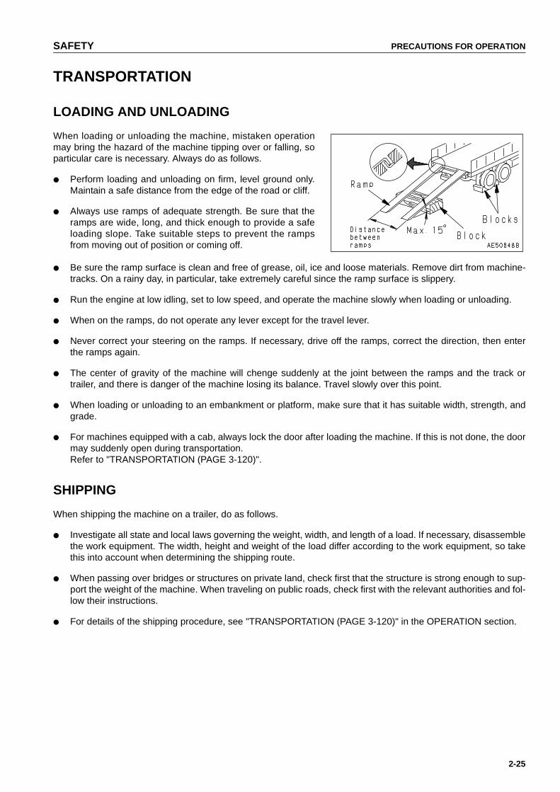
When loading or unloading the machine, mistaken operationmay bring the hazard of the machine tipping over or falling, soparticular care is necessary. Always do as follows.
● Perform loading and unloading on firm, level ground only.Maintain a safe distance from the edge of the road or cliff.
● Always use ramps of adequate strength. Be sure that theramps are wide, long, and thick enough to provide a safeloading slope. Take suitable steps to prevent the rampsfrom moving out of position or coming off.
● Be sure the ramp surface is clean and free of grease, oil, ice and loose materials. Remove dirt from machine-tracks. On a rainy day, in particular, take extremely careful since the ramp surface is slippery.
● Run the engine at low idling, set to low speed, and operate the machine slowly when loading or unloading.
● When on the ramps, do not operate any lever except for the travel lever.
● Never correct your steering on the ramps. If necessary, drive off the ramps, correct the direction, then enterthe ramps again.
● The center of gravity of the machine will chenge suddenly at the joint between the ramps and the track ortrailer, and there is danger of the machine losing its balance. Travel slowly over this point.
● When loading or unloading to an embankment or platform, make sure that it has suitable width, strength, andgrade.
● For machines equipped with a cab, always lock the door after loading the machine. If this is not done, the doormay suddenly open during transportation.Refer to "TRANSPORTATION (PAGE 3-120)".
SHIPPING
When shipping the machine on a trailer, do as follows.
● Investigate all state and local laws governing the weight, width, and length of a load. If necessary, disassemblethe work equipment. The width, height and weight of the load differ according to the work equipment, so takethis into account when determining the shipping route.
● When passing over bridges or structures on private land, check first that the structure is strong enough to sup-port the weight of the machine. When traveling on public roads, check first with the relevant authorities and fol-low their instructions.
● For details of the shipping procedure, see "TRANSPORTATION (PAGE 3-120)" in the OPERATION section.
https://tractormanualz.com

PRECAUTIONS FOR OPERATION SAFETY
2-26
BATTERY
BATTERY HAZARD PREVENTION
Battery electrolyte contains sulphuric acid, and batteries generate flammable hydrogen gas, which may explode.Mistaken handling can lead to serious injury or fire. For this reason, always observe the following precautions.
● Do not use or charge the battery if the battery electrolyte level is below the LOWER LEVEL line. This maycause an explosion. Always check the battery electrolyte level periodically and add distilled water to bring theelectrolyte level to the UPPER LEVEL line.
● When working with batteries, always wear safety glasses and rubber gloves.
● Never smoke or use any flame near the battery.
● If you spill acid on your clothes or skin, immediately flushthe area with large amounts of water.
● If acid gets into your eyes, flush them immediately withlarge quantities of water and seek medical attention.
● Before working with batteries, turn the starting switch to the OFF position.
As there is a hazard that sparks will be generated, always do as follows.
● Do not let tools or other metal objects make any contact between the battery terminals. Do not leave tools orother metal objects lying around near the battery.
● Always disconnect the negative (-) terminal (ground side) first when removing the battery; when installing thebattery, connect the positive (+) terminal first, and connect the ground last. Tighten the battery terminalssecurely.
● Tighten the battery terminals securely.
● Flammable hydrogen gas is generated when the battery is charged, so remove the battery from the chassis,take it to a well-ventilated place, and remove the battery caps before charging it.
● Tighten the battery caps securely.
● Install the battery securely to the determined place.
https://tractormanualz.com

SAFETY PRECAUTIONS FOR OPERATION
2-27
STARTING WITH BOOSTER CABLE
If any mistake is made in the method of connecting the boostercables, it may cause the battery to explode, so always do asfollows.
● When starting with a booster cable, carry out the startingoperation with two workers (one worker sitting in the opera-tor's seat and the other working with the battery).
● When starting from another machine, do not allow the twomachines to touch.
● When connecting the booster cables, turn the startingswitch OFF for both the normal machine and problemmachine. There is a hazard that the machine will movewhen the power is connected.
● Be sure to connect the positive (+) cable first when install-ing the booster cables. Disconnect the ground or negative(-) cable (ground side) first when removing them.
● When removing the booster cables, be careful not to let thebooster cable clips touch each other or to let the clips touchthe machine.
● Always wear safety goggles and rubber gloves when start-ing the engine with booster cables.
● When connecting a normal machine to a problem machine with booster cables, always use a normal machinewith the same battery voltage as the problem machine.
● For details of the starting procedure when using booster cables, see "STARTING ENGINE WITH BOOSTERCABLES (PAGE 3-133)" in the OPERATION section.
https://tractormanualz.com

PRECAUTIONS FOR OPERATION SAFETY
2-28
TOWING
WHEN TOWING
● Injury or death could result if a disabled machine is towedincorrectly or if there is mistake in the selection of the wirerope, so always do as follows.
● Do not tow in a different way from the method given in thesection "METHOD OF TOWING MACHINE (PAGE 3-130)".
● Always wear leather gloves when handling wire rope.
● When carrying out the preparation for towing with anotherworker, agree on signals before starting the operation.
● If your machine is towed by another machine, stop theengine and release the brake. Please contact yourKomatsu distributor to have the brake released.
● It is dangerous to tow a machine on a slope, so choose aplace where there is a gradual slope.If there is no place with a gradual slope, carry out work tomake the slope as small as possible.
● When connecting up a towing machine,do not let anyoneenter the area between the towing machine and the equip-ment being towed.
● Do not straddle the towing cable or wire rope.
● If your machine is towed by another machine, ALWAYS usea wire rope with a sufficient towing capacity.
● Set the towing machine and the towing connection of theequipment being towed in a straight line when connectingit.
● Take up the slack in the wire rope and tow the machine.
● When pulling out the machine getting stuck in mud, use thetowing hook.
● If the machine is stuck in sandy soil, dig out the soil aroundthe towing hook, then use the towing hook to pull themachine out.Permissible load for towing hook: 29,300 kg (288,371 N)
● Never use a wire rope which has cut strands (A), reduceddiameter (B), or kinks (C). There is danger that the ropemay break during the towing operation.
https://tractormanualz.com

SAFETY PRECAUTIONS FOR MAINTENENCE
2-29
PRECAUTIONS FOR MAINTENENCE
WARNING TAG
● Always attach the "DO NOT OPERATE" warning tag to thework equipment control lever in the operator's cab to alertothers that you are performing service or maintenance onthe machine. Attach additional warning tags around themachine if necessary.Warning tag Part No. 09963-A1640Keep this warning tag in the tool box while it is not used. Ifthere is not the tool box, keep the tag in the operation man-ual pocket.
● If others start the engine, or touch or operate the workequipment control lever while you are performing serviceor maintenance, you could suffer serious injury or propertydamage.
KEEP WORK PLACE CLEAN AND TIDY
Do not leave hammers or other tools lying around in the work place. Wipe up all grease, oil, or other substancesthat will cause you to slip. Always keep the work place clean the tidy to enable you to carry out operations safely. Ifthe work place is not kept claen and tidy, there is the danger that you will trip, slip, or fall over and injure yourself.
APPOINT LEADER WHEN WORKING WITH OTHERS
When repairing the machine or when removing and installing the work equipment, appoint a leader and follow hisinstructions during the operation.When working with others, misunderstandings between workers can lead to serious accidents.
https://tractormanualz.com
PRECAUTIONS FOR MAINTENENCE SAFETY
2-30
STOP ENGINE BEFORE CARRYING OUT INSPECTION AND MAINTENANCE
● Stop the machine on firm, level ground.
● Select a place where there is no hazard of falling rocks orlandslides, or of flooding if the land is low.
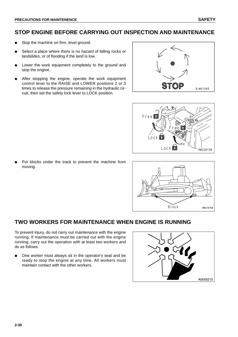
● Lower the work equipment completely to the ground andstop the engine.
● After stopping the engine, operate the work equipmentcontrol lever to the RAISE and LOWER positions 2 or 3times to release the pressure remaining in the hydraulic cir-cuit, then set the safety lock lever to LOCK position.
● Put blocks under the track to prevent the machine frommoving.
TWO WORKERS FOR MAINTENANCE WHEN ENGINE IS RUNNING
To prevent injury, do not carry out maintenance with the enginerunning. If maintenance must be carried out with the enginerunning, carry out the operation with at least two workers anddo as follows.
● One worker must always sit in the operator's seat and beready to stop the engine at any time. All workers mustmaintain contact with the other workers.
https://tractormanualz.com

SAFETY PRECAUTIONS FOR MAINTENENCE
2-31
● Set safety lock lever and brake lock lever to the LOCKposition.
● When carrying out operations near the fan, fan belt, orother rotating parts, there is a hazard of being caught in theparts, so be extremely careful.
● Do not touch any control levers. If any control lever mustbe operated, always give a signal to the other workers towarn them to move to a safe place.
● Never drop or insert tools or other objects into the fan orfan belt. Parts may break or be sent flying.
PROPER TOOLS
Use only tools suited to the task and be sure to use the toolscorrectly. Using damaged, low quality, faulty, makeshift tools orimproper use of the tools could cause serious personal injury.
HANDLING ACCUMULATOR
● On machines equipped with an accumulator, for a short time after the engine is stopped, if the blade controllever is moved to the LOWER position, the work equipment will move down under its own weight.After stopping the engine, always place the safety lever in the LOCK position.
● When releasing the pressure inside the work equipment circuit on machines equipped with an accumulator,follow the procedure given in the following section.Method of releasing pressure : See "HANDLING ACCUMULATOR (PAGE 3-59)".
● The accumulator is filled with high-pressure nitrogen gas, and it is extremely dangerous if it is handled in thewrong way. Always observe the following precautions.
● Never make any hole in the accumulator or expose it to flame or fire.
● Do not weld any boss to the accumulator.
● When disposing the accumulator, it is necessary to release the gas from the accumulator, so please con-tact your Komatsu distributor.
NO UNAUTHORIZED PERSONNEL INTO AREA
Only authorized personnel can service and repair the machine. Do not allow unauthorized personnel into the area.If necessary, employ an observer.
https://tractormanualz.com
PRECAUTIONS FOR MAINTENENCE SAFETY
2-32
ATTACHMENTS
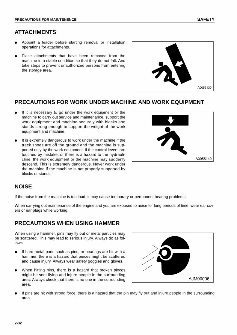
● Appoint a leader before starting removal or installationoperations for attachments.
● Place attachments that have been removed from themachine in a stable condition so that they do not fall. Andtake steps to prevent unauthorized persons from enteringthe storage area.
PRECAUTIONS FOR WORK UNDER MACHINE AND WORK EQUIPMENT
● If it is necessary to go under the work equipment or themachine to carry out service and maintenance, support thework equipment and machine securely with blocks andstands strong enough to support the weight of the workequipment and machine.
● It is extremely dangerous to work under the machine if thetrack shoes are off the ground and the machine is sup-ported only by the work equipment. If the control levers aretouched by mistake, or there is a hazard to the hydrauli-cline, the work equipment or the machine may suddenlydescend. This is extremely dangerous. Never work underthe machine if the machine is not properly supported byblocks or stands.
NOISE
If the noise from the machine is too loud, it may cause temporary or permanent hearing problems.
When carrying out maintenance of the engine and you are exposed to noise for long periods of time, wear ear cov-ers or ear plugs while working.
PRECAUTIONS WHEN USING HAMMER
When using a hammer, pins may fly out or metal particles maybe scattered. This may lead to serious injury. Always do as fol-lows.
● If hard metal parts such as pins, or bearings are hit with ahammer, there is a hazard that pieces might be scatteredand cause injury. Always wear safety goggles and gloves.
● When hitting pins, there is a hazard that broken piecesmight be sent flying and injure people in the surroundingarea. Always check that there is no one in the surroundingarea.
● If pins are hit with strong force, there is a hazard that the pin may fly out and injure people in the surroundingarea.
https://tractormanualz.com
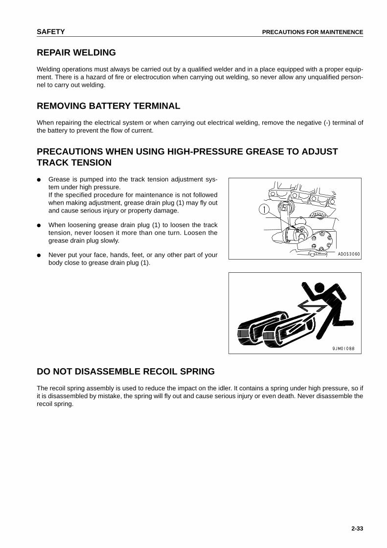
SAFETY PRECAUTIONS FOR MAINTENENCE
2-33
REPAIR WELDING
Welding operations must always be carried out by a qualified welder and in a place equipped with a proper equip-ment. There is a hazard of fire or electrocution when carrying out welding, so never allow any unqualified person-nel to carry out welding.
REMOVING BATTERY TERMINAL
When repairing the electrical system or when carrying out electrical welding, remove the negative (-) terminal ofthe battery to prevent the flow of current.
PRECAUTIONS WHEN USING HIGH-PRESSURE GREASE TO ADJUST TRACK TENSION
● Grease is pumped into the track tension adjustment sys-tem under high pressure.If the specified procedure for maintenance is not followedwhen making adjustment, grease drain plug (1) may fly outand cause serious injury or property damage.
● When loosening grease drain plug (1) to loosen the tracktension, never loosen it more than one turn. Loosen thegrease drain plug slowly.
● Never put your face, hands, feet, or any other part of yourbody close to grease drain plug (1).
DO NOT DISASSEMBLE RECOIL SPRING
The recoil spring assembly is used to reduce the impact on the idler. It contains a spring under high pressure, so ifit is disassembled by mistake, the spring will fly out and cause serious injury or even death. Never disassemble therecoil spring.
https://tractormanualz.com
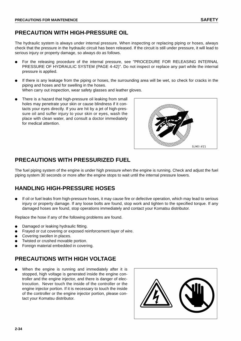
PRECAUTIONS FOR MAINTENENCE SAFETY
2-34
PRECAUTION WITH HIGH-PRESSURE OIL
The hydraulic system is always under internal pressure. When inspecting or replacing piping or hoses, alwayscheck that the pressure in the hydraulic circuit has been released. If the circuit is still under pressure, it will lead toserious injury or property damage, so always do as follows.
● For the releasing procedure of the internal pressure, see "PROCEDURE FOR RELEASING INTERNALPRESSURE OF HYDRAULIC SYSTEM (PAGE 4-42)". Do not inspect or replace any part while the internalpressure is applied.
● If there is any leakage from the piping or hoses, the surrounding area will be wet, so check for cracks in thepiping and hoses and for swelling in the hoses.When carry out inspection, wear safety glasses and leather gloves.
● There is a hazard that high-pressure oil leaking from smallholes may penetrate your skin or cause blindness if it con-tacts your eyes directly. If you are hit by a jet of high-pres-sure oil and suffer injury to your skin or eyes, wash theplace with clean water, and consult a doctor immediatelyfor medical attention.
PRECAUTIONS WITH PRESSURIZED FUEL
The fuel piping system of the engine is under high pressure when the engine is running. Check and adjust the fuelpiping system 30 seconds or more after the engine stops to wait until the internal pressure lowers.
HANDLING HIGH-PRESSURE HOSES
● If oil or fuel leaks from high-pressure hoses, it may cause fire or defective operation, which may lead to seriousinjury or property damage. If any loose bolts are found, stop work and tighten to the specified torque. If anydamaged hoses are found, stop operations immediately and contact your Komatsu distributor.
Replace the hose if any of the following problems are found.
● Damaged or leaking hydraulic fitting.● Frayed or cut covering or exposed reinforcement layer of wire.● Covering swollen in places.● Twisted or crushed movable portion.● Foreign material embedded in covering.
PRECAUTIONS WITH HIGH VOLTAGE
● When the engine is running and immediately after it isstopped, high voltage is generated inside the engine con-troller and the engine injector, and there is danger of elec-trocution. Never touch the inside of the controller or theengine injector portion. If it is necessary to touch the insideof the controller or the engine injector portion, please con-tact your Komatsu distributor.
https://tractormanualz.com

SAFETY PRECAUTIONS FOR MAINTENENCE
2-35
WASTE MATERIAL
To prevent pollution, pay careful attention to the method of disposing of waste materials.
● Always put oil drained from your machine in containers.Never drain oil directly onto the ground or dump into thesewage system, rivers, the sea, or lakes.
● Obey appropriate laws and regulations when disposing ofharmful objects such as oil, fuel, coolant, solvent, filters,and batteries.
MAINTENANCE FOR AIR CONDITIONER
If air conditioner refrigerant gets into your eyes, it may cause blindness; if it touches your skin, it may cause frost-bite. Never touch refrigerant.
COMPRESSED AIR
● When carrying out cleaning with compressed air, there is a hazard of serious injury or property damagecaused by flying particles.
● When using compressed air to clean elements or the radiator, always wear safety goggles, dust mask, gloves,and other protective equipment.
PERIODIC REPLACEMENT OF SAFETY CRITICAL PARTS
● In order for the machine to be operated safely for a long time, it is necessary to add oil and to carry out serviceand maintenance at periodic intervals. In order to further increase safety, components with a strong relation-ship to safety, such as hoses and seat belts, must be replaced at periodic intervals.
Replacement of safety critical parts: See "PERIODIC REPLACEMENT OF SAFETY CRITICAL PARTS(PAGE 4-16)".
● The material of these components naturally changes over time, and repeated use causes deterioration, wear,and fatigue. As a result, there is a hazard that these components may fail and cause serious injury or propertydamage. It is difficult to judge the remaining life of these components from external inspection or the feelingwhen operating, so always replace them at the specified interval.
● Replace or repair safety critical parts if any defect is found, even when they have not reached the time speci-fied interval.
https://tractormanualz.com

3-1
OPERATION31
WARNINGPlease read and make sure that you understand the SAFETYsection before reading this section.
https://tractormanualz.com

GENERAL VIEW OPERATION
3-2
GENERAL VIEW
GENERAL VIEW OF MACHINE
(1) Blade (7) Multi ripper(2) Blade tilt cylinder (8) Ripper lift cylinder(3) Blade lift cylinder (9) Sprocket(4) Cab (10) Track frame(5) Track shoe (11) Frame(6) Ripper tilt cylinder (12) Idler
https://tractormanualz.com

OPERATION GENERAL VIEW
3-3
GENERAL VIEW OF CONTROLS AND GAUGES
Machine equipped with cabMonitor panel specification
(1) Cigarette lighter (9) Brake pedal(2) Fuel control dial (10) Deceleraion pedal(3) Steering, directional and gear shift lever (11) Blade control lever(4) Air conditioner panel or heater panel (12) Horn switch(5) Buzzer cancel switch (13) Ripper control lever(6) Head lamp switch (14) Pin puller control switch (if equipped)(7) Rear lamp switch (15) Safety lock lever(8) Starting switch (16) Parking lever
https://tractormanualz.com

GENERAL VIEW OPERATION
3-4
Machine equipped with canopyMonitor panel specification
(1) Cigarette lighter (9) Deceleration pedal(2) Fuel control dial (10) Blade control lever(3) Steering, directional and gear shift lever (11) Horn switch(4) Buzzer cancel switch (12) Ripper control lever(5) Head lamp switch (13) Pin puller control switch (if equipped)(6) Rear lamp switch (14) Safety lock lever(7) Starting switch (15) Parking lever(8) Brake pedal
https://tractormanualz.com
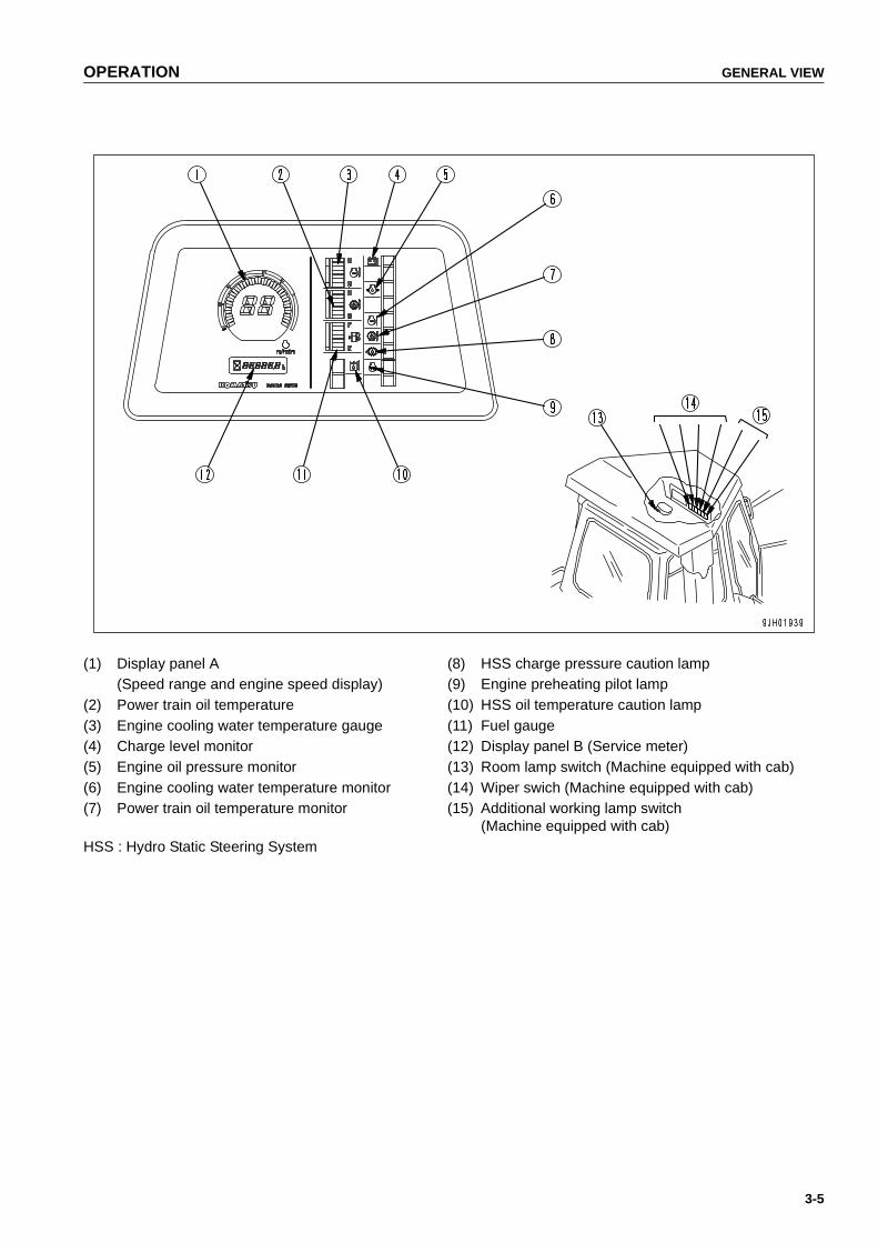
OPERATION GENERAL VIEW
3-5
(1) Display panel A (8) HSS charge pressure caution lamp(Speed range and engine speed display) (9) Engine preheating pilot lamp
(2) Power train oil temperature (10) HSS oil temperature caution lamp(3) Engine cooling water temperature gauge (11) Fuel gauge(4) Charge level monitor (12) Display panel B (Service meter)(5) Engine oil pressure monitor (13) Room lamp switch (Machine equipped with cab)(6) Engine cooling water temperature monitor (14) Wiper swich (Machine equipped with cab)(7) Power train oil temperature monitor (15) Additional working lamp switch
(Machine equipped with cab)HSS : Hydro Static Steering System
https://tractormanualz.com

EXPLANATION OF COMPONENTS OPERATION
3-6
EXPLANATION OF COMPONENTS
The following is an explanation of the devices needed for operating the machine.
To carry out suitable operations correctly and safely,it is important to understand fully the methods of operating theequipment and the meanings of the displays.
Before reading the explanation of components,please read the table below to check what equipment is installed toyour machine.
REMARK● When the key in starting switch is turned to the ON position before starting the engine, the caution lamps (3
seconds) and alarm lamp (2 seconds) light up, and the alarm buzzer (1 second) sounds.● After the engine stops, the caution lamps cannot be checked unless 30 seconds or more lapses.
D155AX-5
Equipment Canopy Cab
Frontpanel
Monitor panel
Air conditioner panel —
Heater panel —
Switch panel (cab) —
Switch panel (canopy) —
Alarm lamp (cab) —
Alarm lamp (canopy) —
Switches
Horn switch
Room lamp switch —
Cigarette lighter —
Wiper switch —
Additional working lamp switch (if equipped) —
Controllevers,pedals,
switches
Fuel control dial
Joystick (counterrotation turning possible)
Brake pedal
Decelerator pedal
Parking lever
Safety lever (for blade control lever, ripper control lever)
Blade control lever
Power tiltdozer specification
Angle dozer specification
Engine Dust indicator
https://tractormanualz.com

OPERATION EXPLANATION OF COMPONENTS
3-7
FRONT PANEL
MONITOR PANEL
A: Caution Items C: Meter Display PortionB: Emergency Stop Items D: Monitor Switches ("SWITCHES (PAGE 3-24)")
A. Caution items (See "CAUTION ITEMS (PAGE 3-9)")
CAUTIONIf these monitor items flash, check and repair the appropriate location as soon as possible.
These are items which need to be observed while the engine is running. If any abnormality occurs, items whichneed to be repaired as soon as possible are displayed.
If there is any abnormality, the appropriate monitor lamp will flash to indicate the location of the abnormality.
B. Emergency stop items (See "EMERGENCY STOP ITEMS (PAGE 3-10)")
CAUTIONIf the monitor for any of these items flashes, stop the engine immediately or run it at low idling, and takethe following action.
This displays those of the abnormality items for which action must be taken immediately when the engine is run-ning.
If there is any abnormality, the monitor showing the location of the abnormality will flash and the alarm buzzer willsound.
https://tractormanualz.com

EXPLANATION OF COMPONENTS OPERATION
3-8
C. Meter Display Portion (See "METER DISPLAY PORTION (PAGE 3-12)")This portion consists of pre-heating pilot lamp, power train oil temperature gauge, engine water temperaturegauge, fuel gauge, service meter and display.
D. Monitor switches (See "SWITCHES (PAGE 3-24)")This select working mode, travel speed and time setting of clock.
https://tractormanualz.com
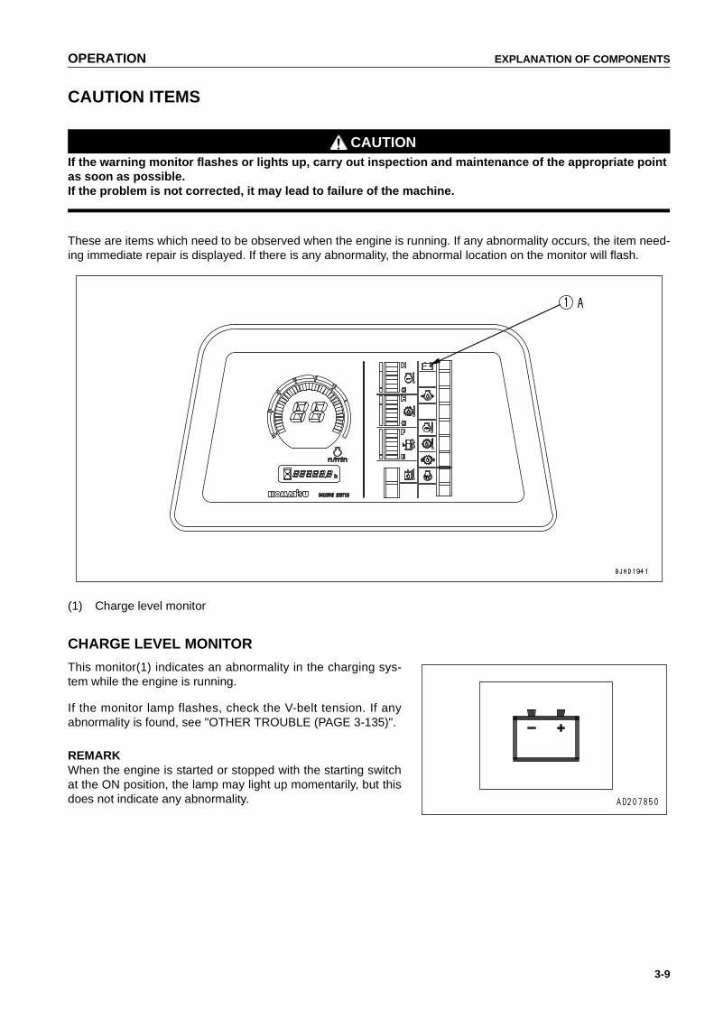
OPERATION EXPLANATION OF COMPONENTS
3-9
CAUTION ITEMS
CAUTIONIf the warning monitor flashes or lights up, carry out inspection and maintenance of the appropriate pointas soon as possible.If the problem is not corrected, it may lead to failure of the machine.
These are items which need to be observed when the engine is running. If any abnormality occurs, the item need-ing immediate repair is displayed. If there is any abnormality, the abnormal location on the monitor will flash.
(1) Charge level monitor
CHARGE LEVEL MONITOR
This monitor(1) indicates an abnormality in the charging sys-tem while the engine is running.
If the monitor lamp flashes, check the V-belt tension. If anyabnormality is found, see "OTHER TROUBLE (PAGE 3-135)".
REMARKWhen the engine is started or stopped with the starting switchat the ON position, the lamp may light up momentarily, but thisdoes not indicate any abnormality.
https://tractormanualz.com

EXPLANATION OF COMPONENTS OPERATION
3-10
EMERGENCY STOP ITEMS
CAUTIONIf any monitor lamp flashes, stop the engine or run it at a low idling speed,and repair it immediately.
These items need to be observed while the engine is running. If any abnormality occurs, items which need to berepaired immediately are displayed. If there is any abnormality, the alarm buzzer sounds intermittently and thecaution lamp for the location of abnormality flashes.
(1) Engine oil pressure monitor (4) HSS charge pressure caution lamp(2) Engine cooling water temperature monitor (5) HSS oil temperature caution lamp(3) Power train oil temperature monitor
ENGINE OIL PRESSURE MONITOR
This monitor (1) indicates a low engine oil pressure.If the monitor lamp flashes, stop the engine and check it imme-diately.
REMARKThe alarm buzzer sounds, when the starting switch is turned toON immediately after the engine oil changed. It does not indi-cate an abnormality.
https://tractormanualz.com

OPERATION EXPLANATION OF COMPONENTS
3-11
ENGINE COOLING WATER TEMPERATURE MONITOR
This monitor (2) indicates a rise in the cooling water tempera-ture.When the monitor lamp flashes, run the engine at the low idlingspeed until the green range of the engine water temperaturegauge lights.
POWER TRAIN OIL TEMPERATURE MONITOR
This monitor (3) indicates a rise in the oil temperature of thetorque converter outlet.When the monitor lamp flashes,run the engine at the low idlingspeed until the green range of the power train oil temperaturegauge lights.
HSS CHARGE PRESSURE CAUTION LAMP
If any drop in the HSS charge pressure is detected by the pres-sure detector, the lamp (4) flashes and the alarm buzzersounds at the same time to warn the operator. If there is anyabnormality, stop the engine immediately and contact yourKomatsu distributor.
HSS OIL TEMPERATURE CAUTION LAMP
This lamp (5) warns of any rise in the oil temperature at theHSS monitor outlet port. If this lamp lights up, run the engine atlow idling or stop the engine and wait for the hydraulic oil tem-perature to go down.
https://tractormanualz.com

EXPLANATION OF COMPONENTS OPERATION
3-12
METER DISPLAY PORTION
NOTICETurn the key in starting switch to the ON position while the engine is at rest, and confirm that the enginewater temperature gauge, power train oil temperature gauge, and fuel gauge, and the caution lamps forthese items light up. If they do not light up, please ask your Komatsu distributor to check them.
The meter display portion consists of the engine water temperature gauge, power train oil temperature gauge, fuelgauge, service meter, and preheating pilot lamp.
(1) Engine cooling water temperature gauge (4) Engine preheating pilot lamp(2) Power train oil temperature gauge (5) Display panel A (3) Fuel gauge (Speed range and engine speed display)
(6) Display panel B (Service meter)
ENGINE COOLING WATER TEMPERATURE GAUGE
This gauge (1) indicates the temperature of the cooling water.If the temperature is normal during operation, the green rangewill light.If the red range lights up during operation, move the Fuel con-trol dial to lower the engine speed to approx. 3/4 of the fullspeed, and run until the water temperature enters the greenrange.If the engine cooling water temperature enters the red range,and the engine water temperature monitor flashes and thealarm buzzer sounds, stop the machine and run at low idlinguntil the water temperature enters the green range.
NOTICEIf the water temperature gauge often enters the red range, check the radiator for clogging.
https://tractormanualz.com

OPERATION EXPLANATION OF COMPONENTS
3-13
POWER TRAIN OIL TEMPERATURE GAUGE
This gauge (2) indicates the oil temperature of the torque con-verter outlet. If the temperature is normal during operation, thegreen range will light.If the red range lights up during operation,move the Fuel con-trol dial to lower the engine speed to approx. 3/4 of the fullspeed, reduce the load and run until the oil temperature entersthe green range.If the power train oil temperature enters the red range, and thepower train oil temperature monitor flashes and the alarmbuzzer sounds, stop the machine and run at low idling until theoil temperature enters the green range.
NOTICEIf the power train oil temperature gauge often enters thered range, we recommend you to lower the travel speedone range (for example, F2 to F1)to reduce the load on thepower train when operating.
FUEL GAUGE
This gauge (3) indicates the amount of fuel in the fuel tank. Ifthere is enough fuel in the tank while the engine is running, thegreen range lights. If the red range lights, there is less than60 (15.84 US gal, 13.20 UK gal)of fuel in the tank.When the red range lights, add fuel.
REMARKThe display is not directly proportional with the remainingamount of fuel.
ENGINE PREHEATING PILOT LAMP
When the electrical heater is used to start the engine in coldweather, this lamp (4) indicates that preheating is being carriedout.When the switch is ON, the preheating pilot lamp on the moni-tor panel lights up. (when the ambient temperature is belowapprox. -5ºC.)
https://tractormanualz.com

EXPLANATION OF COMPONENTS OPERATION
3-14
DISPLAY PANEL A (SPEED RANGE AND ENGINE SPEED DISPLAY)
Meter (5) displays the transmission speed range being used onthe machine and engine speed.
● When the transmission is in 1st FORWARD, the displayshows F1, and when it is in 1st REVERSE, the displayshows R1.
● The peripheral bar graph indicates the engine speed.When the red range lights up during running, shift the gearto a lower speed to run the engine at a speed within thegreen range.
DISPLAY PANEL B (SERVICE METER)
This meter (6) shows the total operation hours of the machine.Set the periodic maintenance intervals using this display.
● The service meter advances while the engine is running -even if the machine is not traveling.
● When the engine is running, the sand glass pilot lamp bythe side of the meters flashes to indicate that the meter isadvancing. Meter will advance by 1 for each hour of opera-tion regardless of the engine speed.
● If any abnormality occurs, an abnormality code and servicehours are alternately displayed on the service meter sec-tion of the display panel B. When an abnormality code isdisplayed during running, see "OTHER TROUBLE (PAGE3-135)".
https://tractormanualz.com
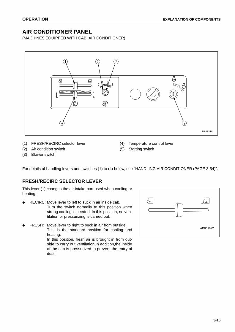
OPERATION EXPLANATION OF COMPONENTS
3-15
AIR CONDITIONER PANEL(MACHINES EQUIPPED WITH CAB, AIR CONDITIONER)
(1) FRESH/RECIRC selector lever (4) Temperature control lever(2) Air condition switch (5) Starting switch(3) Blower switch
For details of handling levers and switches (1) to (4) below, see "HANDLING AIR CONDITIONER (PAGE 3-54)".
FRESH/RECIRC SELECTOR LEVER
This lever (1) changes the air intake port used when cooling orheating.
● RECIRC: Move lever to left to suck in air inside cab.Turn the switch normally to this position whenstrong cooling is needed. In this position, no ven-tilation or pressurizing is carried out.
● FRESH: Move lever to right to suck in air from outside.This is the standard position for cooling andheating.In this position, fresh air is brought in from out-side to carry out ventilation.In addition,the insideof the cab is pressurized to prevent the entry ofdust.
https://tractormanualz.com

EXPLANATION OF COMPONENTS OPERATION
3-16
AIR CONDITION SWITCH
When the switch (2) is pressed and the blue lamp lights up, thecooling function is actuated.Use this switch for cooling or dehu-midifying.
BLOWER SWITCH
This swich (3) acts as the wind flow control switch and mainswitch when cooling or heating.
● The air flow can be set to three stages: 1 (LOW), 2(MEDIUM), 3 (HIGH).
● If the switch is set to 0, the power is switched off and the airconditioner stops.
TEMPERATURE CONTROL LEVER
This lever (4) is used to control the temperature for cooling orheating.
● When the temperature control lever is moved to the right,the temperature of the air coming from the vents becomeslower. (The water valve is losed and the heating function isstopped.)
● When the temperature control lever is moved to the left,the temperature of the air coming from the vents becomeshigher. (The water valve is opened and the heating functionis started.)
https://tractormanualz.com
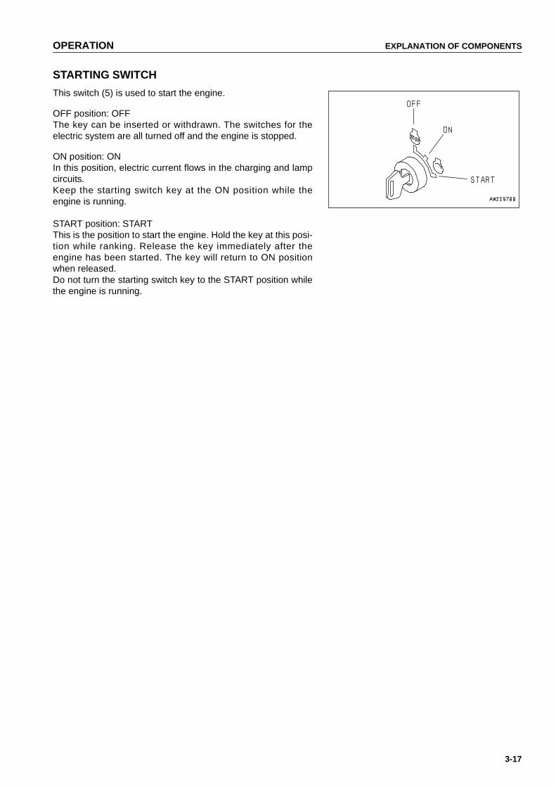
OPERATION EXPLANATION OF COMPONENTS
3-17
STARTING SWITCH
This switch (5) is used to start the engine.
OFF position: OFFThe key can be inserted or withdrawn. The switches for theelectric system are all turned off and the engine is stopped.
ON position: ONIn this position, electric current flows in the charging and lampcircuits.Keep the starting switch key at the ON position while theengine is running.
START position: STARTThis is the position to start the engine. Hold the key at this posi-tion while ranking. Release the key immediately after theengine has been started. The key will return to ON positionwhen released.Do not turn the starting switch key to the START position whilethe engine is running.
https://tractormanualz.com
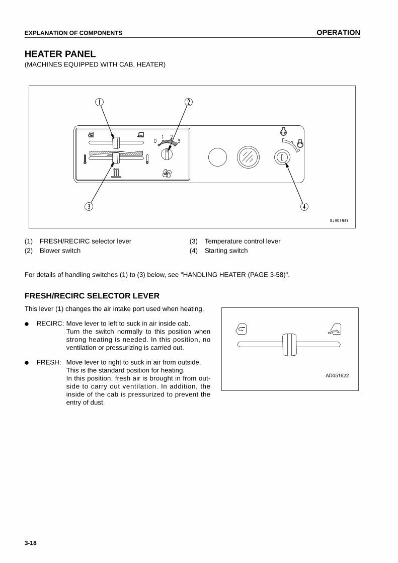
EXPLANATION OF COMPONENTS OPERATION
3-18
HEATER PANEL(MACHINES EQUIPPED WITH CAB, HEATER)
(1) FRESH/RECIRC selector lever (3) Temperature control lever(2) Blower switch (4) Starting switch
For details of handling switches (1) to (3) below, see "HANDLING HEATER (PAGE 3-58)".
FRESH/RECIRC SELECTOR LEVER
This lever (1) changes the air intake port used when heating.
● RECIRC: Move lever to left to suck in air inside cab.Turn the switch normally to this position whenstrong heating is needed. In this position, noventilation or pressurizing is carried out.
● FRESH: Move lever to right to suck in air from outside.This is the standard position for heating.In this position, fresh air is brought in from out-side to carry out ventilation. In addition, theinside of the cab is pressurized to prevent theentry of dust.
https://tractormanualz.com
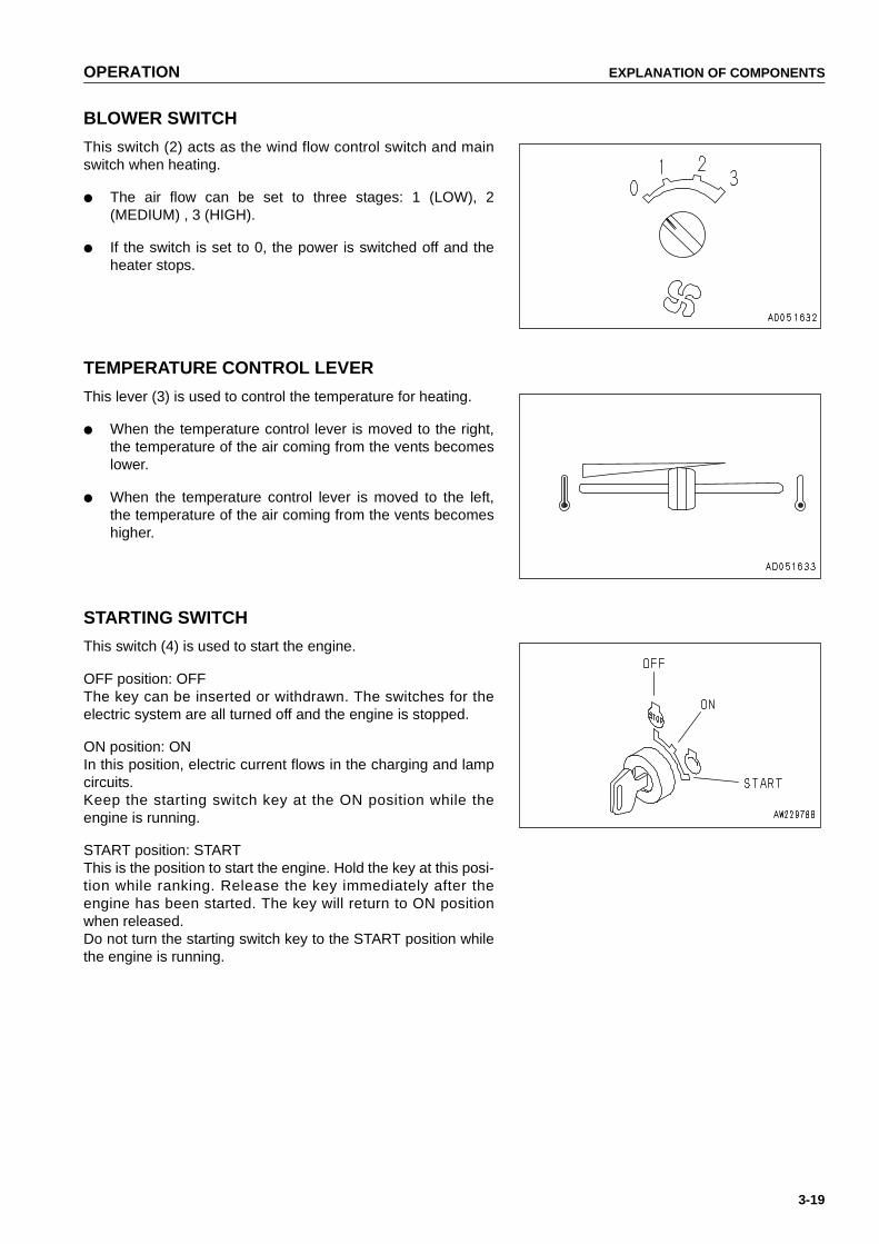
OPERATION EXPLANATION OF COMPONENTS
3-19
BLOWER SWITCH
This switch (2) acts as the wind flow control switch and mainswitch when heating.
● The air flow can be set to three stages: 1 (LOW), 2(MEDIUM) , 3 (HIGH).
● If the switch is set to 0, the power is switched off and theheater stops.
TEMPERATURE CONTROL LEVER
This lever (3) is used to control the temperature for heating.
● When the temperature control lever is moved to the right,the temperature of the air coming from the vents becomeslower.
● When the temperature control lever is moved to the left,the temperature of the air coming from the vents becomeshigher.
STARTING SWITCH
This switch (4) is used to start the engine.
OFF position: OFFThe key can be inserted or withdrawn. The switches for theelectric system are all turned off and the engine is stopped.
ON position: ONIn this position, electric current flows in the charging and lampcircuits.Keep the starting switch key at the ON position while theengine is running.
START position: STARTThis is the position to start the engine. Hold the key at this posi-tion while ranking. Release the key immediately after theengine has been started. The key will return to ON positionwhen released.Do not turn the starting switch key to the START position whilethe engine is running.
https://tractormanualz.com

EXPLANATION OF COMPONENTS OPERATION
3-20
SWITCH PANEL(MACHINES EQUIPPED WITH CAB)
(MACHINES EQUIPPED WITH CANOPY)
(1) Head lamp switch (3) Buzzer cancel switch(2) Rear lamp switch (4) Starting switch (Machine equipped with canopy)
https://tractormanualz.com

OPERATION EXPLANATION OF COMPONENTS
3-21
HEAD LAMP SWITCH
This switch (1) lights up the head lamps.
OFF position: Lamps are outON position: Lamps light up
REAR LAMP SWITCH
This switch (2) lights up the rear lamps.
OFF position: Lamps are outON position: Lamps light up
BUZZER CANCEL SWITCH
Operate this switch (3) to the left or right to stop the alarmbuzzer.
https://tractormanualz.com
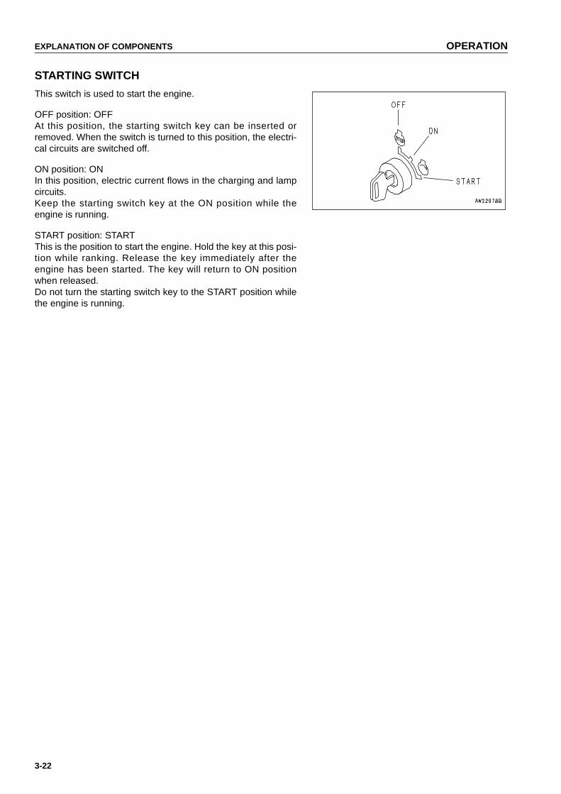
EXPLANATION OF COMPONENTS OPERATION
3-22
STARTING SWITCH
This switch is used to start the engine.
OFF position: OFFAt this position, the starting switch key can be inserted orremoved. When the switch is turned to this position, the electri-cal circuits are switched off.
ON position: ONIn this position, electric current flows in the charging and lampcircuits.Keep the starting switch key at the ON position while theengine is running.
START position: STARTThis is the position to start the engine. Hold the key at this posi-tion while ranking. Release the key immediately after theengine has been started. The key will return to ON positionwhen released.Do not turn the starting switch key to the START position whilethe engine is running.
https://tractormanualz.com
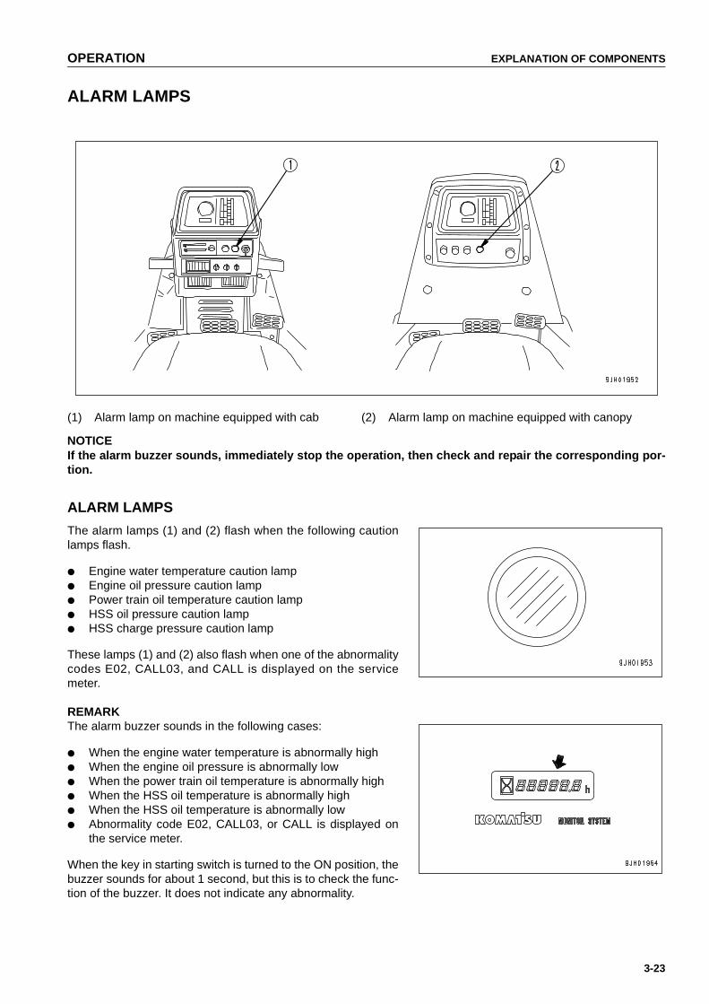
OPERATION EXPLANATION OF COMPONENTS
3-23
ALARM LAMPS
(1) Alarm lamp on machine equipped with cab (2) Alarm lamp on machine equipped with canopy
NOTICEIf the alarm buzzer sounds, immediately stop the operation, then check and repair the corresponding por-tion.
ALARM LAMPS
The alarm lamps (1) and (2) flash when the following cautionlamps flash.
● Engine water temperature caution lamp● Engine oil pressure caution lamp● Power train oil temperature caution lamp● HSS oil pressure caution lamp● HSS charge pressure caution lamp
These lamps (1) and (2) also flash when one of the abnormalitycodes E02, CALL03, and CALL is displayed on the servicemeter.
REMARKThe alarm buzzer sounds in the following cases:
● When the engine water temperature is abnormally high● When the engine oil pressure is abnormally low● When the power train oil temperature is abnormally high● When the HSS oil temperature is abnormally high● When the HSS oil temperature is abnormally low● Abnormality code E02, CALL03, or CALL is displayed on
the service meter.
When the key in starting switch is turned to the ON position, thebuzzer sounds for about 1 second, but this is to check the func-tion of the buzzer. It does not indicate any abnormality.
https://tractormanualz.com

EXPLANATION OF COMPONENTS OPERATION
3-24
SWITCHES
The sketch shows the D155AX-5 (with cab, monitor panel specification).
(1) Horn switch (4) Wiper switch (machines equipped with cab)(2) Room lamp switch (machines equipped with cab) (5) Additional working lamp switch(3) Cigarette lighter (machines equipped with cab) (machines equipped with cab)
HORN SWITCH
The horn sounds when the button (1) at the rear of the bladecontrol lever at the right side of the operator's seat is pressed.
https://tractormanualz.com

OPERATION EXPLANATION OF COMPONENTS
3-25
ROOM LAMP SWITCH(MACHINES EQUIPPED WITH CAB)
This switch (2) lights up the room lamp.
ON position: Lamp lights upOFF position: Lamp is out
CIGARETTE LIGHTER(MACHINES EQUIPPED WITH CAB)
This switch (3) is used to light igarettes.When the cigarette lighter is pushed in, it will return to its origi-nal position after a few seconds, so take it out to light your cig-arette.
NOTICEThis cigarette lighter is 24V. Do not use it as the powersource for 12 V equipment.
WIPER SWITCH(MACHINES EQUIPPED WITH CAB)
This switch (4) activates the wipers.The wiper switches are as follows.
(A) Left door(B) Front window(C) Right door(D) Rear window
This is also used as the window washer switch.The switch is operated as follows.
● Window washer onlyKeep the switch pressed to the OFF position to spray outwater.
https://tractormanualz.com

EXPLANATION OF COMPONENTS OPERATION
3-26
● Wiper onlyIf this is switched on, the wiper will start.
● Wiper and window washerIf this is kept pressed to the ON position while the wiper isworking,water will be sprayed out.
ADDITIONAL WORKING LAMP SWITCH(MACHINES EQUIPPED WITH CAB) (OPTION)
This switch (5) is used to turn on the additional working lamp.
(A) Head lamp switch(B) Rear lamp switch
Push in the direction of the arrow to turn on the lamps.
https://tractormanualz.com

OPERATION EXPLANATION OF COMPONENTS
3-27
REMARK● When installing the cab, check the colors of the washer
tank and window washer hoses, and be sure to connectcorrectly.
● When installing the cab, please contact your Komatsu dis-tributor for installation.
https://tractormanualz.com
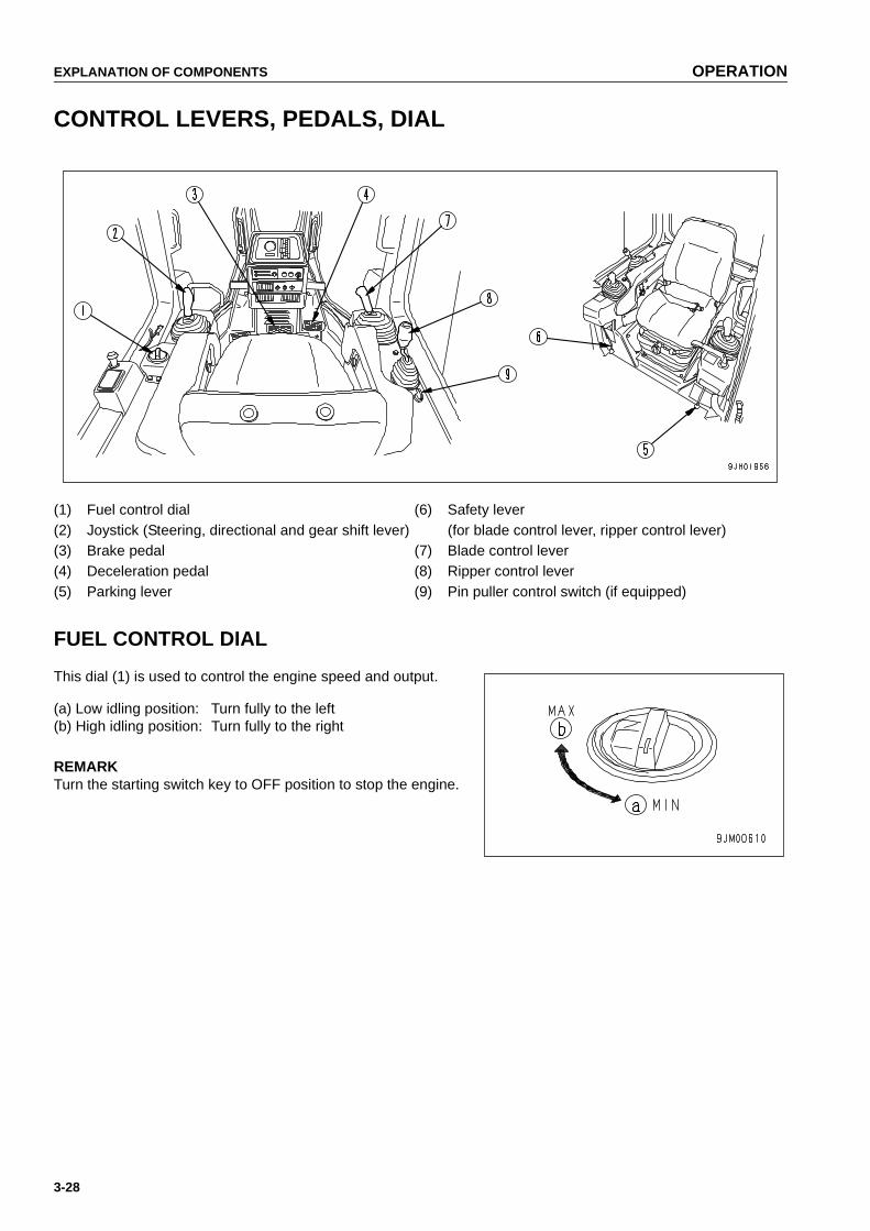
EXPLANATION OF COMPONENTS OPERATION
3-28
CONTROL LEVERS, PEDALS, DIAL
(1) Fuel control dial (6) Safety lever(2) Joystick (Steering, directional and gear shift lever) (for blade control lever, ripper control lever)(3) Brake pedal (7) Blade control lever(4) Deceleration pedal (8) Ripper control lever(5) Parking lever (9) Pin puller control switch (if equipped)
FUEL CONTROL DIAL
This dial (1) is used to control the engine speed and output.
(a) Low idling position: Turn fully to the left(b) High idling position: Turn fully to the right
REMARKTurn the starting switch key to OFF position to stop the engine.
https://tractormanualz.com

OPERATION EXPLANATION OF COMPONENTS
3-29
JOYSTICK(STEERING, DIRECTIONAL AND GEAR SHIFT LEVER)
This lever (2) is used to switch between forward and reverse tosteer and gear shift the machine or carry out counterrotationturns.
● Switching between forward and reverse
Position (a) : FORWARDPosition (b) : REVERSEPosition N : Neutral
● Steering operations
Position (L) : Left turnPosition (R) : Right turn
When the lever is pushed forward, the machine will travel for-ward, and when it is moved back, the machine will travel inreverse.When the lever is being set to the FORWARD or REVERSEposition, if it is moved to the left or right to steer the machine,the machine will turn smoothly in the direction of the lever witha turning angle that matches the amount the lever is moved.If this lever is operated fully to the left or right, the turningradius will become smaller.
REMARK● When carrying out turning operations, if the lever is
released, it will return to position (a) or (b) and the machinewill travel in a straight line.
● During steering operations, if you use the lever guide tosupport your hand,the turning performance wil l beimproved.
● Gear shifting
Rotate the joystick 30º to carry out gear shifting operation.
Position (A) : 1stPosition (B) : 2ndPosition (C) : 3rd
https://tractormanualz.com

EXPLANATION OF COMPONENTS OPERATION
3-30
For details of the maximum speed at each speed range,see "SPECIFICATIONS (PAGE 5-2)".
When gear shifting operation is carried out, the displaypanel A will display the used speed range.
1st: F1, R1, or N1 is displayed2nd: F2, R2, or N2 is displayed3rd: F3, R3, or N3 is displayed
● Counterrotation turn
WARNINGWhen carrying out a counterrotation turn, if the load is notequal on the left and right sides, the machine may carryout a pivot turn, so check the ground conditions and becareful not to hit any obstacles.
If the lever is operated partially in the direction of turn with thelever at the (N) position, the left and right tracks will rotate inopposite directions and the machine will turn smoothly on thespot. If the steering lever is operated fully, the speed of thecounterrotation turn will increase.
https://tractormanualz.com

OPERATION EXPLANATION OF COMPONENTS
3-31
BRAKE PEDAL
WARNINGDo not place your foot on this pedal unnecessarily.
Depress the pedal (3) to apply the right and left brakes.
DECELERATION PEDAL
WARNING● Do not place your foot on this pedal unnecessarily.
● When passing over the top of a hill or when a load is dumped over a cliff, the load is suddenlyreduced, so there is danger that the travel speed will also increase suddenly. To prevent this, depressthe decelerator pedal to reduce the travel speed.
This pedal (4) is used for reducing the engine speed or stop-ping the machine.
Depress this pedal to reduce the speed when shifting betweenforward and reverse or when stopping the machine.
PARKING LEVER
WARNINGWhen the machine is parked, always set the parking lever to the LOCK position.
This lever (5) is used to apply the parking brake.
REMARK● If the steering, directional, and gearshift lever is at the
FORWARD or REVERSE position and the parking brakelever is operated to the LOCK position, the steering, direc-tional, and gearshift lever is automatically returned to the Nposition.
● When starting the engine, if the parking lever is not at thelock position, the engine does not start.
https://tractormanualz.com
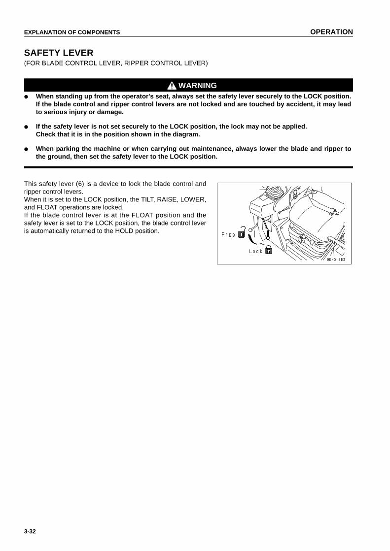
EXPLANATION OF COMPONENTS OPERATION
3-32
SAFETY LEVER(FOR BLADE CONTROL LEVER, RIPPER CONTROL LEVER)
WARNING● When standing up from the operator's seat, always set the safety lever securely to the LOCK position.
If the blade control and ripper control levers are not locked and are touched by accident, it may leadto serious injury or damage.
● If the safety lever is not set securely to the LOCK position, the lock may not be applied.Check that it is in the position shown in the diagram.
● When parking the machine or when carrying out maintenance, always lower the blade and ripper tothe ground, then set the safety lever to the LOCK position.
This safety lever (6) is a device to lock the blade control andripper control levers.When it is set to the LOCK position, the TILT, RAISE, LOWER,and FLOAT operations are locked.If the blade control lever is at the FLOAT position and thesafety lever is set to the LOCK position, the blade control leveris automatically returned to the HOLD position.
https://tractormanualz.com
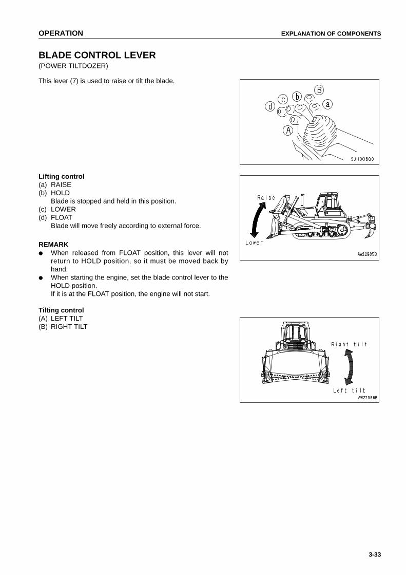
OPERATION EXPLANATION OF COMPONENTS
3-33
BLADE CONTROL LEVER(POWER TILTDOZER)
This lever (7) is used to raise or tilt the blade.
Lifting control(a) RAISE(b) HOLD
Blade is stopped and held in this position.(c) LOWER(d) FLOAT
Blade will move freely according to external force.
REMARK● When released from FLOAT position, this lever will not
return to HOLD position, so it must be moved back byhand.
● When starting the engine, set the blade control lever to theHOLD position.If it is at the FLOAT position, the engine will not start.
Tilting control(A) LEFT TILT(B) RIGHT TILT
https://tractormanualz.com
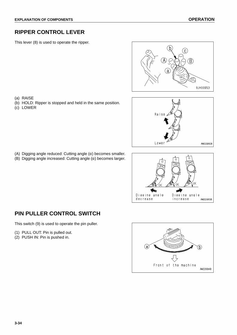
EXPLANATION OF COMPONENTS OPERATION
3-34
RIPPER CONTROL LEVER
This lever (8) is used to operate the ripper.
(a) RAISE(b) HOLD: Ripper is stopped and held in the same position.(c) LOWER
(A) Digging angle reduced: Cutting angle (α) becomes smaller.(B) Digging angle increased: Cutting angle (α) becomes larger.
PIN PULLER CONTROL SWITCH
This switch (9) is used to operate the pin puller.
(1) PULL OUT: Pin is pulled out.(2) PUSH IN: Pin is pushed in.
https://tractormanualz.com

OPERATION EXPLANATION OF COMPONENTS
3-35
DUST INDICATOR
This device indicates that the air cleaner element is clogged.For details on how to lean the element, see "CHECK, CLEANAND REPLACE AIR CLEANER ELEMENT (PAGE 4-25)".
POWER SOURCE
The cigarette lighter socket can be used as a power source.The capacity of the cigarette lighter power source is 120 W(24V x 5A).
NOTICEThe power from the cigarette lighter socket is 24 V. Do notuse this as the power source for any 12 V equipment.
https://tractormanualz.com

EXPLANATION OF COMPONENTS OPERATION
3-36
FUSE BOX
NOTICEBefore replacing a fuse, be sure to turn off the starting switch.
The fuses protect the electrical equipment and wiring from burning out.If the fuse becomes corroded, or white powder can be seen, or the fuse is loose in the fuse holder, replace thefuse.Replace a fuse with another of the same capacity.
● ChassisWhen the battery cover is opened,fuse box (1) can befound inside.
● Cab (machines equipped with cab)Fuse box (2) is installed at the bottom of the overheadpanel.
https://tractormanualz.com

OPERATION EXPLANATION OF COMPONENTS
3-37
FUSE CAPACITY AND NAME OF CIRCUIT
Fuse box (1)
Fuse box (2) (machine equipped with cab)
No. Fuse capacity Circuit Remarks
(1) 15 A Horn, pin puller
(2) 15 A Engine
(3) 20 A Rear lamp
(4) 20 A Front lamp
(5) 10 A Controller,HSS
(6) 15 AMonitor pannel, alarm buzzer
(7) — —
(8) 20 A Air conditioner
(9) 20 A Backup alarm
(10) 10 A Cab, key switch Power circuit
No. Fuse capacity Circuit
(1) 10 A Radio memory
(2) 20 A Radio, lamp, cigarette lighter
(3) 10 A Rear wiper
(4) 10 A Right door wiper
(5) 10 A Front wiper
(6) 10 A Left door wiper
https://tractormanualz.com

EXPLANATION OF COMPONENTS OPERATION
3-38
DOOR-OPEN LOCK(MACHINES EQUIPPED WITH CAB)
Use this when you want to keep the door held open.
1. Push the door against door catch (1). The door will beheld by the door catch.
2. To release the door, move lever (2) inside the cab to thefront of the cab. This will release the catch.
NOTICE● When keeping the door open, fix it securely to the
catch.● Always close the door when traveling or carrying out
operations. Leaving the door open will cause the doorto break.
● Keep the door locked open securely.The door may swing closed because of the vibration.
SASH GLASS INTERMEDIATE LOCK(MACHINES EQUIPPED WITH CAB)
When carrying out operations with the cab sash glass open,use this block to prevent the glass from moving.
● When the lever is at the FREE position, the glass can beopened or losed.
● When the lever is moved to the LOCK (up or down)posi-tion, the glass is fixed in position.
● If the glass is not held securely, set the lever in the FREEposition and rotate lockwise to strengthen the holdingpower.
● To reduce the holding power, turn counterclockwise.
https://tractormanualz.com

OPERATION EXPLANATION OF COMPONENTS
3-39
HOT AND COOL BOX(MACHINES EQUIPPED WITH CAB)
This is at the top of the front panel. It can be used to warm orcool three canned drinks.
This is interconnected with the air conditioner: During heating,it warms up the drinks; during cooling, it cools down the drinks.
DOOR POCKET(MACHINES EQUIPPED WITH CAB)
These are on the inside of the left and right doors, and can beused for keeping things. However, do not put tools or otherheavy objects in the pocket. If the pocket becomes dirty, turnthree clips (1), remove the pocket and wash it.
ASHTRAY(MACHINES EQUIPPED WITH CAB)
This is on the left side of the operator's seat.Always make sure that you extinguish the cigarette before clos-ing the lid.
https://tractormanualz.com

EXPLANATION OF COMPONENTS OPERATION
3-40
TOOL BOX
This is inside the right engine side cover.It is used for storing tools.
https://tractormanualz.com
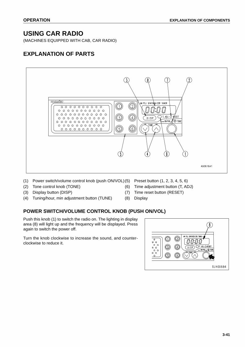
OPERATION EXPLANATION OF COMPONENTS
3-41
USING CAR RADIO(MACHINES EQUIPPED WITH CAB, CAR RADIO)
EXPLANATION OF PARTS
(1) Power switch/volume control knob (push ON/VOL)(5) Preset button (1, 2, 3, 4, 5, 6)(2) Tone control knob (TONE) (6) Time adjustment button (T, ADJ)(3) Display button (DISP) (7) Time reset button (RESET)(4) Tuning/hour, min adjustment button (TUNE) (8) Display
POWER SWITCH/VOLUME CONTROL KNOB (PUSH ON/VOL)
Push this knob (1) to switch the radio on. The lighting in displayarea (8) will light up and the frequency will be displayed. Pressagain to switch the power off.
Turn the knob clockwise to increase the sound, and counter-clockwise to reduce it.
https://tractormanualz.com
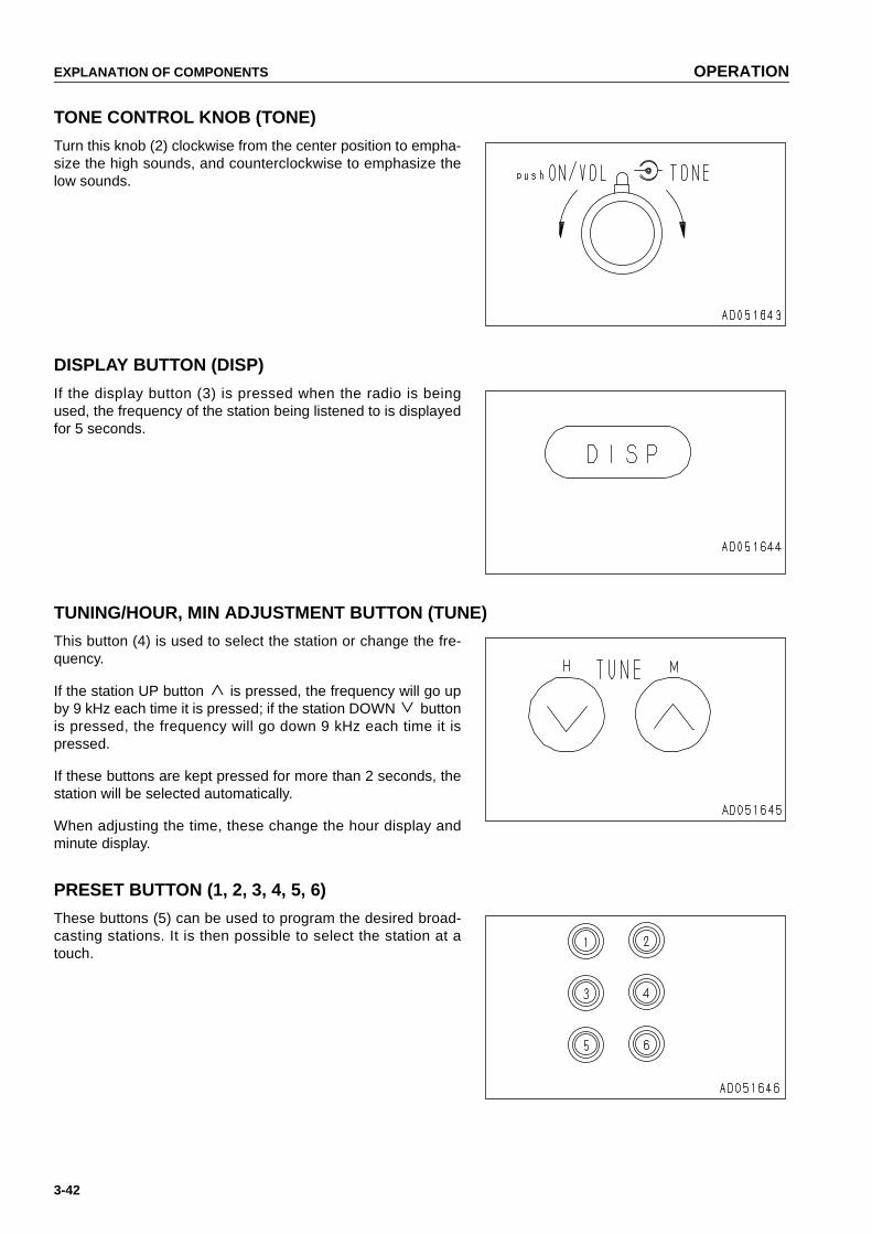
EXPLANATION OF COMPONENTS OPERATION
3-42
TONE CONTROL KNOB (TONE)
Turn this knob (2) clockwise from the center position to empha-size the high sounds, and counterclockwise to emphasize thelow sounds.
DISPLAY BUTTON (DISP)
If the display button (3) is pressed when the radio is beingused, the frequency of the station being listened to is displayedfor 5 seconds.
TUNING/HOUR, MIN ADJUSTMENT BUTTON (TUNE)
This button (4) is used to select the station or change the fre-quency.
If the station UP button is pressed, the frequency will go upby 9 kHz each time it is pressed; if the station DOWN buttonis pressed, the frequency will go down 9 kHz each time it ispressed.
If these buttons are kept pressed for more than 2 seconds, thestation will be selected automatically.
When adjusting the time, these change the hour display andminute display.
PRESET BUTTON (1, 2, 3, 4, 5, 6)
These buttons (5) can be used to program the desired broad-casting stations. It is then possible to select the station at atouch.
https://tractormanualz.com

OPERATION EXPLANATION OF COMPONENTS
3-43
TIME ADJUSTMENT BUTTON (T, ADJ)
Press this button (6) to adjust the time.
TIME RESET BUTTON (RESET)
Press this button (7) to reset to the exact hour.
DISPLAY
This display (8) displays the frequency, time, and preset sym-bols.
https://tractormanualz.com

EXPLANATION OF COMPONENTS OPERATION
3-44
METHOD OF USE
Method of setting preset buttons
1. Press power switch (1). The frequency is displayed indisplay area (8).
2. Use selector button (4) ( or ) to adjust to the desiredfrequency.
3. Choose a preset button to use for this station, and keep itpressed for at least 2 seconds to program the button tothat frequency.
When the sound suddenly disappears and appears again, the button is programmed, and the preset number isshown in display area (8) .After programming the button, press the preset button and release it within approx. 2 sec.The station programmedto that button will be selected for reception.It is possible to program one station for each preset button.
Method of manual tuning
Press the tuning button lightly to adjust to the desired fre-quency.Each time the button is pressed, the frequency will change by 9kHz.
button: Select station at higher frequency button: Select station at lower frequency
Method of automatic tuning
Keep the tuning button pressed for at least 2 seconds and thenrelease it. When reception from a broadcasting station ispicked up, the selector will automatically stop at that position.When searching for the next station, keep the selector buttonpressed again for at least 2 seconds.
button: Select station at higher frequency button: Select station at lower frequency
If the reception is weak, and stations are not found,adjust thefrequency manually to select the desired station.
https://tractormanualz.com

OPERATION EXPLANATION OF COMPONENTS
3-45
Adjusting time
1. Keep T.ADJ button (6) pressed, and press H button (A).The hour display will change, so when it reaches the cor-rect hour, release the button.
2. Keep T.ADJ button (6) pressed and press M button (B).The minute display will change, so when it reaches thecorrect time, release the button.
Method of using RESET button
If RESET button (7) is pressed at the same time as the timesignal or standard time, the display will return immediately tothe exact hour ( hour 00 min).
If the display is 01 - 29 min, the display will go back to 0 min.If the display is 30 - 59 min, the display will advance to 0 min.
[Example]10:29 to 10:00 (return to exact hour)10:30 to 11:00 (advances to exact hour)
PRECAUTIONS WHEN USING
● For safety reasons, when operating keep the sound to a level where you can enjoy the sound but still hear thesound from outside the cab.
● If water gets inside the speaker case or car radio (auto tuning), it may cause a serious problem, so do not letwater get on these parts.
● Do not wipe the knobs or buttons or any other parts with any solvent such as benzene or thinner. Always wipewith a soft dry cloth (in cases of extreme dirt, use alcohol on the cloth).
https://tractormanualz.com
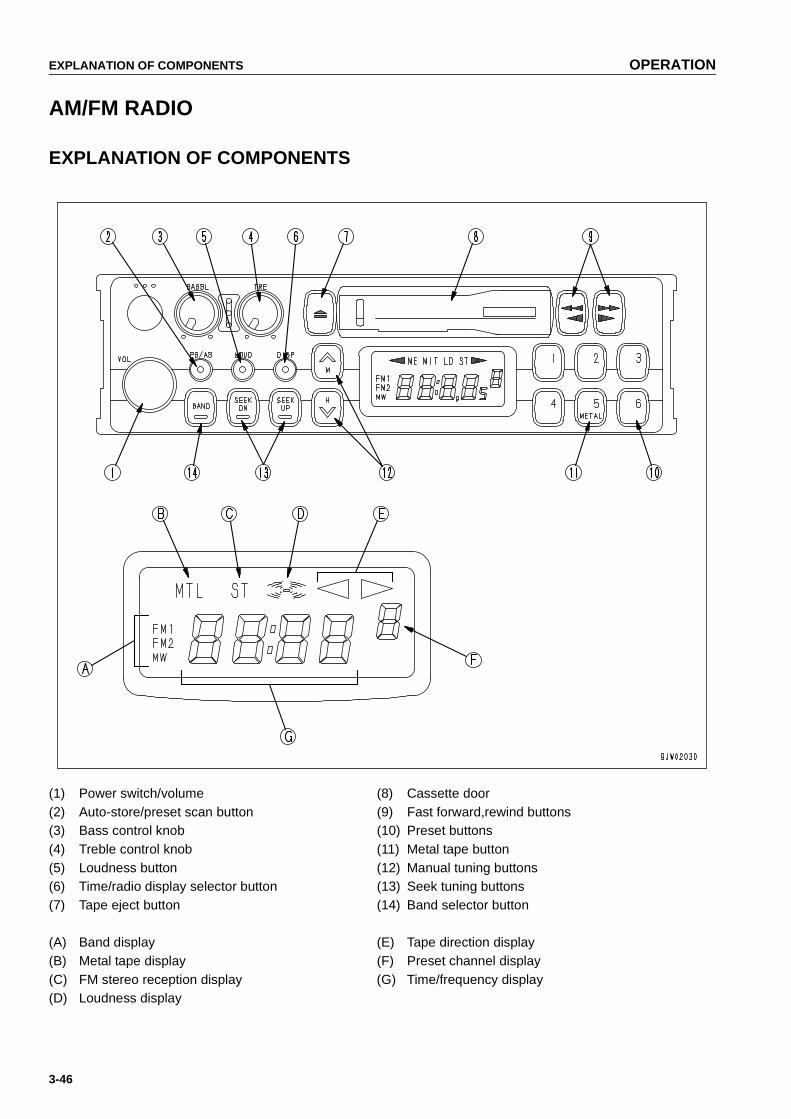
EXPLANATION OF COMPONENTS OPERATION
3-46
AM/FM RADIO
EXPLANATION OF COMPONENTS
(1) Power switch/volume (8) Cassette door(2) Auto-store/preset scan button (9) Fast forward,rewind buttons(3) Bass control knob (10) Preset buttons(4) Treble control knob (11) Metal tape button(5) Loudness button (12) Manual tuning buttons(6) Time/radio display selector button (13) Seek tuning buttons(7) Tape eject button (14) Band selector button
(A) Band display (E) Tape direction display(B) Metal tape display (F) Preset channel display(C) FM stereo reception display (G) Time/frequency display(D) Loudness display
https://tractormanualz.com

OPERATION EXPLANATION OF COMPONENTS
3-47
POWER SWITCH/VOLUME
Turn this knob (1) to the right until it clicks to turn the power on.Turn it further to increase the volume.
AUTO-STORE/PRESET SCAN BUTTON
Use this button (2) to actuate the preset scan and auto-storefunctions.
● Auto-storeIf this button is pressed for at least 2 seconds during radioreception, the system will automatically search for radio sta-tions within the same band and will store the frequency in thepreset memory. During this operation, the channel display onthe right side of the display will change.This shows that the frequency is being saved to each memorychannel.
REMARKThe auto-store function cannot be used when the channel dis-play is flashing.When the display is flashing, the preset scan function is beingused.
● Preset scanIf this button is pressed for less than 2 seconds during radioreception, the stations preset in the present reception band arebroadcast for 5 seconds each from No.1 to No.6.To listen to the desired station, press the button again. After thepreset scan operation is completed, it will return to normalbroadcasting.
BASS CONTROL KNOB
Turn this button (3) to the left to reduce the low tones; turn it tothe right to emphasize the low tones.
Direction (a): Low tone reducedDirection (b): Low tone emphasized
https://tractormanualz.com

EXPLANATION OF COMPONENTS OPERATION
3-48
TREBLE CONTROL KNOB
Turn this button (4) to the left to reduce the low tones; turn it tothe right to emphasize the high tones.
Direction (a): High tone reducedDirection (b): High tone emphasized
LOUDNESS BUTTON
This button (5) is used when playing at low volume. It makes itpossible to hear more easily by emphasizing the low tone whenit is felt that the low tones are weak.
Push button: Actuated (ON)Push button again: Canceled (OFF)
TIME/RADIO DISPLAY SELECTOR BUTTON
This button (6) is used to switch between the "Radio/tape dis-play" and the "Time display".
● Correcting timePress the button to set to the time display.
(A) Correcting hour: Keep the DISP button pressed andpress the bottom tuning button (H) tocorrect the hour.
(B) Correcting minute: Keep the DISP button pressed andpress the top tuning button (M) to cor-rect the minute.
https://tractormanualz.com
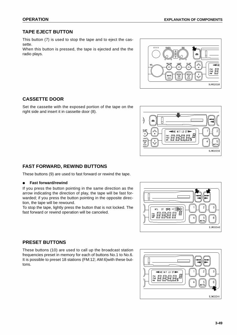
OPERATION EXPLANATION OF COMPONENTS
3-49
TAPE EJECT BUTTON
This button (7) is used to stop the tape and to eject the cas-sette.When this button is pressed, the tape is ejected and the theradio plays.
CASSETTE DOOR
Set the cassette with the exposed portion of the tape on theright side and insert it in cassette door (8).
FAST FORWARD, REWIND BUTTONS
These buttons (9) are used to fast forward or rewind the tape.
● Fast forward/rewindIf you press the button pointing in the same direction as thearrow indicating the direction of play, the tape will be fast for-warded; if you press the button pointing in the opposite direc-tion, the tape will be rewound.To stop the tape, lightly press the button that is not locked. Thefast forward or rewind operation will be canceled.
PRESET BUTTONS
These buttons (10) are used to call up the broadcast stationfrequencies preset in memory for each of buttons No.1 to No.6.It is possible to preset 18 stations (FM:12; AM:6)with these but-tons.
https://tractormanualz.com

EXPLANATION OF COMPONENTS OPERATION
3-50
METAL TAPE BUTTON(used also for preset button No.5)
This button (11) is used when playing a metal or chrome tape.This button is used also for preset button No.5. When it ispressed, "MTL" appears on the display.
MANUAL TUNING BUTTONS
When the button of button (12) is pressed, the frequencygoes up 9 kHz for AM or 0.1 MHz for FM; when the button ofbutton is pressed, the frequency goes down 9 kHz for AM or0.1 MHz for FM.If the button is kept pressed, the frequency will change continu-ously.
SEEK TUNING BUTTONS
When the "SEEK UP" button of button (13) is pressed, the fre-quency automatically goes up; when the "SEEK DOWN" buttonof button is pressed, the frequency automatically goes down.When the next station that can be received is found, it automat-ically stops.
BAND SELECTOR BUTTON
When this button (14) is pressed, the band is switched betweenFM1, FM2, and MW(AM). The band is shown on the display.
https://tractormanualz.com

OPERATION EXPLANATION OF COMPONENTS
3-51
METHOD OF OPERATION
METHOD OF SETTING PRESET BUTTONS
To listen to a preset station, use band selector button (1) toselect AM, FM1, or FM2, then press the preset switch numberto listen to the desired station.It is possible to preset six AM stations and 12 FM stations(FM1:6, FM2:6).
1. If you are playing a cassette, press the tape eject buttonto stop the tape.
2. Select the station to be preset.Use band selector button (1) to select MW (AM), FM1, orFM2, then use the manual tuning button to select the fre-quency of the broadcasting station.
3. Press manual memory button (2) or seek tuning button(3).
4. Press preset button (4) of the number to be preset for 2seconds while the frequency display is being shown onthe display. (The preset channel and frequency are dis-played and the presetting is completed).
5. Repeat Steps 2 to 4 to preset other stations.
REMARK● Use Steps 2 to 4 also when changing the setting of a preset switch to another station.● When the power is disconnected, such as when the battery is replaced, all the settings are deleted,so preset
the stations again.
MANUAL MEMORY BUTTON
Select the station to be preset with manual tuning button (1) orseek tuning button (2), then keep button No.1 to button No.6 ofbutton (3) pressed for 2 seconds while the frequency is beingdisplayed to preset the station.
https://tractormanualz.com

EXPLANATION OF COMPONENTS OPERATION
3-52
LISTENING TO RADIO
1. Turn the starting switch ON, then turn power switch (1)ON.
2. Set band selector button (2) to AM or FM.
3. Select the station with the preset buttons or manual tun-ing button (3).
4. Adjust the volume, balance, and tone as desired.
5. When turning the radio OFF, turn power switch (1) to theleft until there is a click.
REMARK● To switch to the radio when listening to a cassette, press the cassette eject button to stop the tape.● If you insert a cassette when listening to the radio, the tape will start to play.
LISTENING TO CASSETTE TAPE
1. Turn the starting switch ON, then turn power switch (1)ON.
2. Set the cassette with the exposed portion of the tape onthe right side and push it into the cassette door. The tapewill automatically start playing.If the arrow indicating the direction of play is pointing tothe right, the top side is being played; if the arrow is point-ing to the left, the bottom side is being played.When the tape reaches the end, it is automaticallyreversed and the other side starts to play.
3. When finishing with the tape, press the cassette ejectbutton to eject the tape and automatically switch to theradio.
https://tractormanualz.com
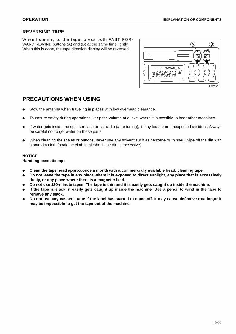
OPERATION EXPLANATION OF COMPONENTS
3-53
REVERSING TAPE
When l i s ten ing to the tape, press both FAST FOR-WARD,REWIND buttons (A) and (B) at the same time lightly.When this is done, the tape direction display will be reversed.
PRECAUTIONS WHEN USING
● Stow the antenna when traveling in places with low overhead clearance.
● To ensure safety during operations, keep the volume at a level where it is possible to hear other machines.
● If water gets inside the speaker case or car radio (auto tuning), it may lead to an unexpected accident. Alwaysbe careful not to get water on these parts.
● When cleaning the scales or buttons, never use any solvent such as benzene or thinner. Wipe off the dirt witha soft, dry cloth (soak the cloth in alcohol if the dirt is excessive).
NOTICEHandling cassette tape
● Clean the tape head approx.once a month with a commercially available head. cleaning tape.● Do not leave the tape in any place where it is exposed to direct sunlight, any place that is excessively
dusty, or any place where there is a magnetic field.● Do not use 120-minute tapes. The tape is thin and it is easily gets caught up inside the machine.● If the tape is slack, it easily gets caught up inside the machine. Use a pencil to wind in the tape to
remove any slack.● Do not use any cassette tape if the label has started to come off. It may cause defective rotation,or it
may be impossible to get the tape out of the machine.
https://tractormanualz.com

EXPLANATION OF COMPONENTS OPERATION
3-54
HANDLING AIR CONDITIONER(MACHINES EQUIPPED WITH CAB)
COOLING OPERATION
When the cooling operation is carried out, the inside of the cab is cooled, and at the same time the drinks insidethe hot and cool box can be cooled.
Cooling (RECIRC)
When the control switch and lever are operated as shown inthe diagram, a cool breeze is sent out.Use this position when strong cooling is needed.
● Press switch (2).
● Place levers (1) and (4) in the position shown in the dia-gram.
● Set switch (3) to the desired position.
Cooling (FRESH)
If the air inside the cab is no longer fresh, set FRESH/RECIRCselector lever (1) to FRESH to bring in fresh air. Keep the otherswitches at the same positions as for cooling (RECIRC).In this position, the inside of the cab is pressurized to preventthe entry of dust.
REMARK● If the cooling effect is reduced, set FRESH/RECIRC selec-
tor lever (1) to RECIRC again.This increases the coolingeffect.
● New Freon R134a is used as the refrigerant.● The tightening torque for the air conditioner gas piping
thread is as follows.
Thread size Tightening torque N•m (kgf•m)
Discharge 22 x 1.5 19.6 to 24.5 (2 to 2.5)
Liquid 16 x 1.5 11.8 to 14.7 (1.2 to 1.5)
Suction 24 x 1.5 29.4 to 24.3 (3 to 3.5)
https://tractormanualz.com
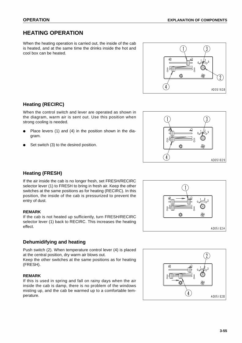
OPERATION EXPLANATION OF COMPONENTS
3-55
HEATING OPERATION
When the heating operation is carried out, the inside of the cabis heated, and at the same time the drinks inside the hot andcool box can be heated.
Heating (RECIRC)
When the control switch and lever are operated as shown inthe diagram, warm air is sent out. Use this position whenstrong cooling is needed.
● Place levers (1) and (4) in the position shown in the dia-gram.
● Set switch (3) to the desired position.
Heating (FRESH)
If the air inside the cab is no longer fresh, set FRESH/RECIRCselector lever (1) to FRESH to bring in fresh air. Keep the otherswitches at the same positions as for heating (RECIRC). In thisposition, the inside of the cab is pressurized to prevent theentry of dust.
REMARKIf the cab is not heated up sufficiently, turn FRESH/RECIRCselector lever (1) back to RECIRC. This increases the heatingeffect.
Dehumidifying and heating
Push switch (2). When temperature control lever (4) is placedat the central position, dry warm air blows out.Keep the other switches at the same positions as for heating(FRESH).
REMARKIf this is used in spring and fall on rainy days when the airinside the cab is damp, there is no problem of the windowsmisting up, and the cab be warmed up to a comfortable tem-perature.
https://tractormanualz.com
EXPLANATION OF COMPONENTS OPERATION
3-56
PRECAUTIONS WHEN USING AIR CONDITIONER
Carry out ventilation from time to time when using the cooler.● If you smoke when the cooler is on, the smoke may start to hurt your eyes, so turn the lever to FRESH to
remove the smoke while continuing the cooling.
● When running the air conditioner for a long time, turn the lever to the FRESH position once an hour to carryout ventilation and cooling.
Be careful not to make the temperature in the cab too low.● When the cooler is on, set the temperature so that it feels slightly cool when entering the cab (5 - 6ºC lower
than the outside temperature). This temperature difference is considered to the most suitable for your health,so always be careful to adjust the temperature properly.
Direction of vents when cooling● If the vents (left and right)in the middle of the dashboard are turned so that cold air plays directly on the cab
door glass, moisture may condense on the outside of the cab door glass and reduce the visibility. (This occursparticularly in high temperatures.)If this happens, turn the vent shutter selector lever to stop the air going directly to the glass and direct itupward.
INSPECTION DURING OFF-SEASON
Even during the off-season, run the compressor at low speed for several minutes once a week to prevent the lossof the oil film at the lubricated parts of the compressor. (Run the engine at low speed and set the temperature con-trol lever at the central position.)
REMARKWhen the ambient temperature is low, if the compressor is suddenly run at high speed, it may cause failure of thecompressor.Note that the system is set so that the compressor will not run when the cooler switch is turned on if the ambienttemperature is less than 2 - 6.5ºC.
PROCEDURE FOR REPLACING RECEIVER
Replace the receiver once every two years.After replacing the receiver, add compressor oil. Turn the old receiver at an angle and measure the oil remaininginside the receiver, then add the same amount of oil (Denso Oil 6) to fill the new receiver.
REMARK● Depending on the condition of use, the replacement interval may be shorter.● If the receiver is used when the desiccant has exceeded the water absorption limit, the refrigerant ircuit may
become clogged and cause failure of the compressor.
Precautions when replacing receiver
● If the receiver is left for more than 15 minutes with the blind cover removed, the moisture in the air will beabsorbed, and this will reduce the life of the desiccant. If you remove the blind cover, connect the pipingquickly, evacuate the system and fill with refrigerant.
● When removing the refrigerant from the refrigerant ircuit, release it gradually from the low pressure side to pre-vent oil from flowing out.
https://tractormanualz.com

OPERATION EXPLANATION OF COMPONENTS
3-57
CLEANING AIR FILTER
If the air filter for the FRESH or RECIRC air intake becomes clogged, the cooling or heating capacity will drop. Toprevent this, clean the air filter with compressed air once a week.
For details of the cleaning method, see "CLEAN AIR CONDITIONER AIR FILTER (PAGE 4-36)".
CLEAN AIR CONDITIONER CONDENSER FINS
If the air conditioner condenser fins are clogged, the cooling capacity will drop.To prevent this, lean the air condi-tioner condenser fins with compressed air.
For details of the cleaning method, see "CLEAN, CHECK AIR CONDITIONER CONDENSER FINS (PAGE 4-34)".
https://tractormanualz.com
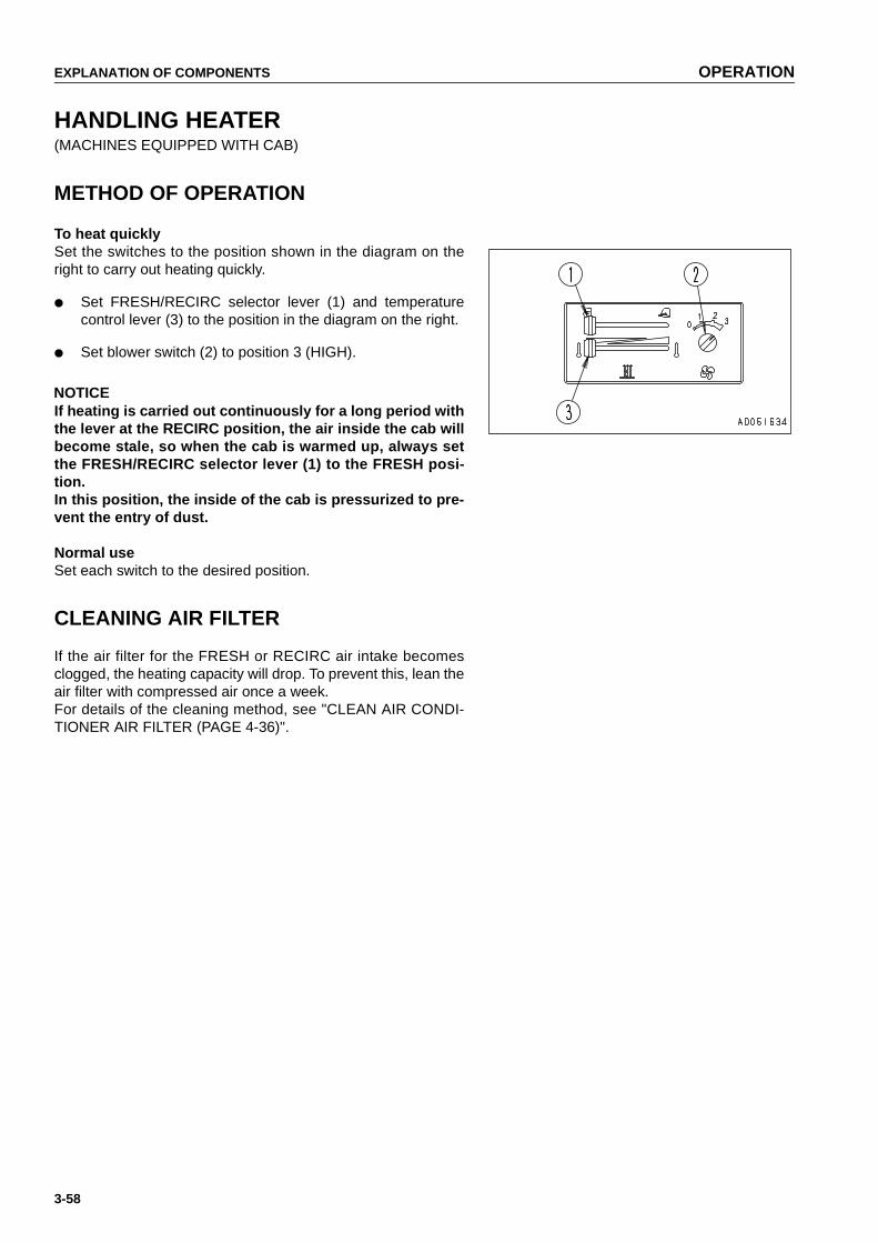
EXPLANATION OF COMPONENTS OPERATION
3-58
HANDLING HEATER(MACHINES EQUIPPED WITH CAB)
METHOD OF OPERATION
To heat quicklySet the switches to the position shown in the diagram on theright to carry out heating quickly.
● Set FRESH/RECIRC selector lever (1) and temperaturecontrol lever (3) to the position in the diagram on the right.
● Set blower switch (2) to position 3 (HIGH).
NOTICEIf heating is carried out continuously for a long period withthe lever at the RECIRC position, the air inside the cab willbecome stale, so when the cab is warmed up, always setthe FRESH/RECIRC selector lever (1) to the FRESH posi-tion.In this position, the inside of the cab is pressurized to pre-vent the entry of dust.
Normal useSet each switch to the desired position.
CLEANING AIR FILTER
If the air filter for the FRESH or RECIRC air intake becomesclogged, the heating capacity will drop. To prevent this, lean theair filter with compressed air once a week.For details of the cleaning method, see "CLEAN AIR CONDI-TIONER AIR FILTER (PAGE 4-36)".
https://tractormanualz.com

OPERATION EXPLANATION OF COMPONENTS
3-59
HANDLING ACCUMULATOR
WARNINGOn machines equipped with an accumulator, for a short time after the engine is stopped, if the workequipment control lever is moved to the LOWER position, the work equipment will move down under itsown weight.After stopping the engine, always place the safety lever in the LOCK position.
The accumulator is filled with high-pressure nitrogen gas, and it is extremely dangerous if it is handled inthe wrong way.Always observe the following precautions.
● Never make any hole in the accumulator or expose it to flame or fire.
● Do not weld any boss to the accumulator.
● When disposing of the accumulator, it is necessary to release the gas from the accumulator, soplease contact your Komatsu distributor.
The accumulator is a device to store the pressure in the controlcircuit, and when it is installed, the control circuit can be oper-ated for a short time even after the engine is stopped. There-fore, if the control lever is moved in the direction to lower thework equipment, it is possible for the work equipment to moveunder its own weight.The accumulator is installed to the position shown in the dia-gram on the right.
METHOD OF RELEASING PRESSURE IN OPERATING CIRCUIT ON MACHINE EQUIPPED WITH ACCUMULATOR
1. Lower the work equipment and stop the engine.
2. After stopping the engine, operate the control lever fully to the front, rear, left, and right to release the pres-sure inside the work equipment ircuit.However, the pressure cannot be completely removed, so when removing the work equipment ircuit, loosenthe screw slowly, and never stand in the direction where the oil spurts out.
https://tractormanualz.com

OPERATION OPERATION
3-60
OPERATION
CHECK BEFORE STARTING ENGINE
WALK-AROUND CHECK
Before starting the engine, look around the machine and under the machine to check for loose nut or bolts, or leak-age of oil, fuel, or coolant, and check the condition of the work equipment and hydraulic system. Check also forloose wiring, play, and accumulation of dust at places which reach high temperatures.
WARNINGRemove any flammable materials from around the battery or engine muffler, or other high temperatureengine parts. Leakage of fuel or oil will cause the machine to catch fire. Check carefully, and be sure torepair any abnormalities, or please contact your Komatsu distributor.
When inspecting,if the machine is at an angle,move it to a horizontal place to carry out the check.
Before starting the engine, look around the machine and under the machine to check for loose nut or bolts, or leak-age of oil, fuel, or coolant, and check the condition of the work equipment and hydraulic system. Check also forloose wiring, play, and collection of dust at places which reach high temperatures.
Always carry out the items in this section before starting the engine each day.
1. Check for damage, wear, play in work equipment, cylinders, linkage,hosesCheck that there are no cracks, excessive wear, or play in the work equipment, cylinders, linkage, or hoses. Ifany abnormality is found, repair it.
2. Remove dirt and dust from around engine, battery radiatorCheck if there is any dirt or dust accumulated around the engine or radiator. Check also if there is any flamma-ble material (dead leaves, twigs, grass, etc.)accumulated around the battery or high temperature engine parts,such as the engine muffler or turbocharger. Remove all such dirt or flammable material.
3. Check for leakage of water or oil around engineCheck that there is no leakage of oil from the engine or leakage of water from the cooling system. If any abnor-mality is found, repair it.
4. Check for leakage of oil from power train case, final drive case, hydraulic tank, hose, jointsCheck that there is no oil leakage. If any abnormality is found, repair the place where the oil is leaking.Check for leakage of oil from the undercover. Check the ground for traces of oil leakage.
5. Check the undercarriage (track, sprocket, idler, guard) for damage, wear, loose bolts, or leakage of oilfrom rollers If any damage, wear, or oil leakage is found, repair the problem and tighten the bolts.
6. Check for damage to handrail, loose boltsRepair any damage and tighten any loose.
7. Check for damage to gauges, lamps on instrument panel, loose boltsCheck that there is no damage to the panel, gauges and lamps.If any abnormality is found, replace the parts. Clean off any dirt on the surface.
8. Check for damage to seat belt and mounting clampsCheck that there is no abnormality in the seat belt or mounting clamps. If there is any damage, replace withnew parts.
https://tractormanualz.com

OPERATION OPERATION
3-61
CHECK BEFORE STARTING
Always carry out the items in this section before starting the engine each day.
CHECKING WITH MACHINE MONITOR(MONITOR PANEL SPECIFICATION)
1. Turn starting switch (1) to the ON position.
2. Check that all monitor lamps light up for 3 seconds, thewarning lamp lights up for 2 seconds, and the alarmbuzzer sounds for (1) second.
REMARKIf the lamps do not light up,there may be a failure or disconnec-tion in the monitor, so please contact your Komatsu distributor.
NOTICEWhen carrying out the checks before starting, do not relayonly on the monitor. Always carry out all the items listedfor periodic maintenance.
https://tractormanualz.com

OPERATION OPERATION
3-62
CHECK COOLANT LEVEL, ADD WATER
WARNING● Normally, do not open the radiator cap. When checking the cooling water level, check the sub-tank
when the engine is cold.
● Do not remove the cap when the radiator water is hot. Boiling water may spurt out. After the watertemperature goes down, turn the cap slowly to release the pressure, then remove it.
1. Open the engine side cover on the left side of the chas-sis, and check that the cooling water is between theFULL and LOW marks on sub-tank (1). If the water levelis low, add water to the FULL level through the water fillerport in sub-tank (1).
REMARKThe coolant may overflow from the sub-tank drain hose. This isno problem. It occurs because too much coolant has beenadded.
2. After adding water, tighten the cap securely.
3. If the sub-tank is empty, check for leakage of water, thenadd water to the radiator and sub-tank.
4. After adding water, close the engine side cover.
https://tractormanualz.com

OPERATION OPERATION
3-63
CHECK FUEL LEVEL, ADD FUEL
WARNINGWhen adding fuel, never let the fuel overflow. This may cause a fire. If you spill fuel, thoroughly clean upany spillage.
1. Turn the engine starting switch to the ON position andcheck the fuel level with fuel level gauge (G) on the mon-itor panel.After checking, turn the switch back to the OFF position.
2. After completing work, fill the fuel tank through fuel fillerport (F).
3. After adding fuel, tighten the cap securely.Fuel capacity: 625 (165 US gal)
REMARKIf breather hole (1) on the cap is logged, the pressure in thetank will drop and fuel will not flow.Clean the hole from time to time.
https://tractormanualz.com

OPERATION OPERATION
3-64
DRAIN WATER,SEDIMENT FROM FUEL TANK
Loosen drain valve (1) at the bottom of the fuel tank and drainthe sediment and water accumulated at the bottom of the tanktogether with the fuel.
https://tractormanualz.com
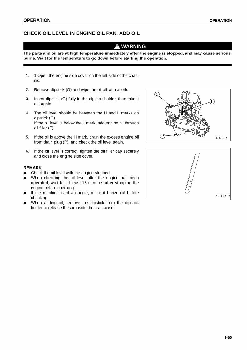
OPERATION OPERATION
3-65
CHECK OIL LEVEL IN ENGINE OIL PAN, ADD OIL
WARNINGThe parts and oil are at high temperature immediately after the engine is stopped, and may cause seriousburns. Wait for the temperature to go down before starting the operation.
1. 1.Open the engine side cover on the left side of the chas-sis.
2. Remove dipstick (G) and wipe the oil off with a loth.
3. Insert dipstick (G) fully in the dipstick holder, then take itout again.
4. The oil level should be between the H and L marks ondipstick (G).If the oil level is below the L mark, add engine oil throughoil filler (F).
5. If the oil is above the H mark, drain the excess engine oilfrom drain plug (P), and check the oil level again.
6. If the oil level is correct, tighten the oil filler cap securelyand close the engine side cover.
REMARK● Check the oil level with the engine stopped.● When checking the oil level after the engine has been
operated, wait for at least 15 minutes after stopping theengine before checking.
● If the machine is at an angle, make it horizontal beforechecking.
● When adding oil, remove the dipstick from the dipstickholder to release the air inside the crankcase.
https://tractormanualz.com
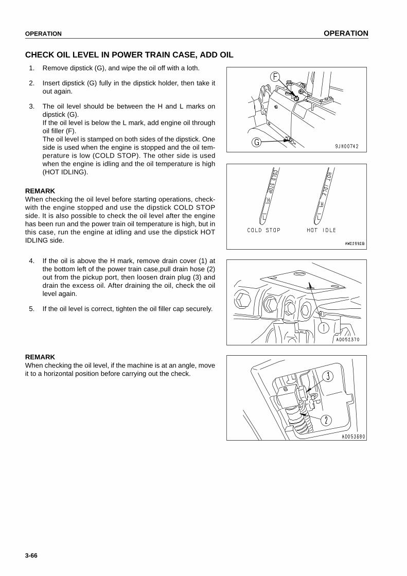
OPERATION OPERATION
3-66
CHECK OIL LEVEL IN POWER TRAIN CASE, ADD OIL
1. Remove dipstick (G), and wipe the oil off with a loth.
2. Insert dipstick (G) fully in the dipstick holder, then take itout again.
3. The oil level should be between the H and L marks ondipstick (G).If the oil level is below the L mark, add engine oil throughoil filler (F).The oil level is stamped on both sides of the dipstick. Oneside is used when the engine is stopped and the oil tem-perature is low (COLD STOP). The other side is usedwhen the engine is idling and the oil temperature is high(HOT IDLING).
REMARKWhen checking the oil level before starting operations, check-with the engine stopped and use the dipstick COLD STOPside. It is also possible to check the oil level after the enginehas been run and the power train oil temperature is high, but inthis case, run the engine at idling and use the dipstick HOTIDLING side.
4. If the oil is above the H mark, remove drain cover (1) atthe bottom left of the power train case,pull drain hose (2)out from the pickup port, then loosen drain plug (3) anddrain the excess oil. After draining the oil, check the oillevel again.
5. If the oil level is correct, tighten the oil filler cap securely.
REMARKWhen checking the oil level, if the machine is at an angle, moveit to a horizontal position before carrying out the check.
https://tractormanualz.com

OPERATION OPERATION
3-67
CHECK BRAKE PEDAL TRAVEL
Drive the machine, depress the brake pedal, and check that themachine stops.
CHECK DAMPER CASE OIL LEVEL, ADD OIL
1. Open engine side cover (1) on the left side of themachine.
2. Remove dipstick (G), and wipe the oil off with a loth.
3. Insert dipstick (G) fully into the dipstick holder, then pull itout again.
4. The oil level should be between the H and L marks ondipstick (G).If the oil is below the L mark, add engine oil through thedipstick holder.
5. If the oil is above the H mark, open inspection cover (2) atthe bottom center of the power train case, and drain theexcess oil from drain plug (P) of the engine damper (thiscan be seen to the front of the machine through theinspection window). After draining the oil, check the oillevel again.
REMARK● Check the oil level with the engine stopped.● When checking the oil level, if the machine is at an angle,
move it to a horizontal position before carrying out thecheck.
https://tractormanualz.com

OPERATION OPERATION
3-68
CHECK OIL LEVEL IN HYDRAULIC TANK, ADD OIL
WARNING● When removing the oil filler cap, oil may spurt out, so
stop the engine and wait for the oil temperature to godown, then turn the cap slowly to release the internalpressure before removing the cap.
● If oil has been added to above the H mark, stop theengine and wait for the hydraulic oil to cool down.Then remove drain plug (P), loosen drain valve (1),and drain the excess oil.
1. Lower the blade to the ground, stop the engine and waitfor about 5 minutes before checking oil level. If the oillevel is between H and L in sight gauge (G), it is normal.
NOTICEDo not add oil if the level is above the H line. This will dam-age the hydraulic equipment and cause the oil to spurt out.
2. If the level is below the L mark, add engine oil through oilfiller (F).
REMARKWhen inspecting, if the machine is at an angle, move it to ahorizontal place to carry out the check.
https://tractormanualz.com

OPERATION OPERATION
3-69
CHECK DUST INDICATOR
1. Open the engine side Cover on the left side of the chas-sis, and check that the red piston has not appeared inthe transparent portion of dust indicator (1).
2. If the red piston has appeared, clean or replace the ele-ment immediately.For details of the method of cleaning the element, see"CHECK, CLEAN AND REPLACE AIR CLEANER ELE-MENT (PAGE 4-25)".
3. After checking, cleaning, and replacing, press the knob ofdust indicator (1) to return the red piston to its originalposition.
CHECK ELECTRIC WIRINGS
WARNING● If the fuses are frequently blown or if there are traces of short circuits on the electrical wiring, locate
the cause immediately and carry out repairs, or contact your Komatsu distributor for repairs.
● If flammable materials (dead leaves, twigs, dry grass, etc.) accumulate around the battery, they willcause fire, so always remove such material immediately.
● Keep the top surface of the battery clean and check the breather hole in the battery cap. If it isclogged with dirt or dust, wash the battery cap to clean the breather hole.
Check for damage and wrong capacity of the fuse and any sign of disconnection or short circuit in the electric wir-ing. Check also for loose terminals and tighten any loose parts.
Check the wiring of the "battery", "starting motor" and "alternator" carefully in particular.
When carrying out walk-around checks or checks before starting, always check if there is any accumulation offlammable material around the battery, and remove such flammable material.
Please contact your Komatsu distributor for investigation and correction of the cause.
https://tractormanualz.com

OPERATION OPERATION
3-70
CHECK THAT LAMPS LIGHT UP
1. Turn the key of starting switch (1) to the ON position.
2. Turn the front lamp switch (2) and rear lamp switch (3) tothe ON position and check that the front lamp and rearlamp light up.
If the lamps do not light up, there is probably a brokenbulb or disconnection in the wiring, so contact yourKomatsu distributor for repairs.
https://tractormanualz.com
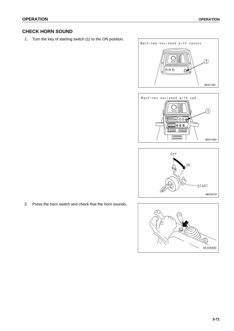
OPERATION OPERATION
3-71
CHECK HORN SOUND
1. Turn the key of starting switch (1) to the ON position.
2. Press the horn switch and check that the horn sounds.
https://tractormanualz.com

OPERATION OPERATION
3-72
CHECK BACKUP ALARM SOUND
1. Turn the key of starting switch (1) to the ON position.
2. Set the joystick to the REVERSE position. The buzzermust sound immediately. The buzzer will continue tosound until the joystick is moved to the NEUTRAL orFORWARD position.
https://tractormanualz.com
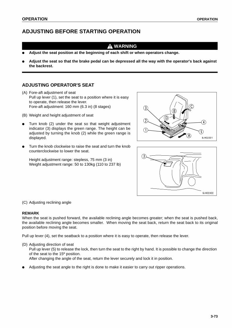
OPERATION OPERATION
3-73
ADJUSTING BEFORE STARTING OPERATION
WARNING● Adjust the seat position at the beginning of each shift or when operators change.
● Adjust the seat so that the brake pedal can be depressed all the way with the operator's back againstthe backrest.
ADJUSTING OPERATOR'S SEAT
(A) Fore-aft adjustment of seatPull up lever (1), set the seat to a position where it is easy to operate, then release the lever.Fore-aft adjustment: 160 mm (6.3 in) (8 stages)
(B) Weight and height adjustment of seat
● Turn knob (2) under the seat so that weight adjustmentindicator (3) displays the green range. The height can beadjusted by turning the knob (2) while the green range isdisplayed.
● Turn the knob clockwise to raise the seat and turn the knobcounterclockwise to lower the seat.
Height adjustment range: stepless, 75 mm (3 in)Weight adjustment range: 50 to 130kg (110 to 237 lb)
(C) Adjusting reclining angle
REMARKWhen the seat is pushed forward, the available reclining angle becomes greater; when the seat is pushed back,the available reclining angle becomes smaller. When moving the seat back, return the seat back to its originalposition before moving the seat.
Pull up lever (4), set the seatback to a position where it is easy to operate, then release the lever.
(D) Adjusting direction of seatPull up lever (5) to release the lock, then turn the seat to the right by hand. It is possible to change the direction of the seat to the 15º position.After changing the angle of the seat, return the lever securely and lock it in position.
● Adjusting the seat angle to the right is done to make it easier to carry out ripper operations.
https://tractormanualz.com

OPERATION OPERATION
3-74
ADJUSTING MIRROR(MACHINES EQUIPPED WITH CAB)
Loosen screw (1) which is installed on the mirror, and adjustthe mirror to the best position to see the mirror from the opera-tor's seat.Especially for seeing behind the machine, adjust in such a waythat you can easily see persons at the rear L.H and R.H cor-ners.
https://tractormanualz.com

OPERATION OPERATION
3-75
USING SEAT BELT
Always install a seat belt on machines equipped with ROPS.
WARNING● Before fitting the seat belt, check that there is no abnormality in the mounting bracket and mounting
belt of the belt. If the belt is worn or damaged, replace it.
● Replace the seat belt every three years, even if their outside is free from abnormality. The year of man-ufacture is woven on the back side of the belt.
● Always fasten the seat belt before starting operations.
● Always use the seat belt during operations.
● Do not twist the left or right side of the seat belt when fastening it.
FASTENING AND REMOVING BELT1. Sit on the seat, depress the brake pedal fully, and adjust the seat so that your back is pressed against the
backrest.
2. After adjusting the seat position, adjust tether belt(1).Tense the tether belt and install it when there is no onesitting on the seat.
3. Sit on the seat and hold tongue(4) connected to wind-inmechanism(2) and pull out the belt slowly so that the beltwill cover your abdomen sufficiently.
4. Insert tongue(4) in buckle(3) until it clicks. The belt ispulled back into wind-in mechanism(2) until it is fitted toyour abdomen. The belt is locked under this conditionand cannot be extended anymore. Fit the belt to yourabdomen without twisting it.
REMARKIf the belt is locked before the tongue is inserted in the buckle,let it return to the wind-in mechanism, then repeat the aboveprocedure from the first.
5. Pull the belt to check that it is securely locked in position.
6. When removing the belt, press the red button on buckle(3).The belt will automatically be wound in.
Check that the bolts of the clamp securing the belt to the chassis are not loose. Tighten them if they are loose. Thetightening torque for the mounting bolt is 24.5 ± 4.9 N•m (2.5 ± 0.5 kgf•m,18.1 ± 3.6 lbft).If the belt surface is scratched or frayed or if the fittings are broken or deformed, replace the seat belt unit.
https://tractormanualz.com
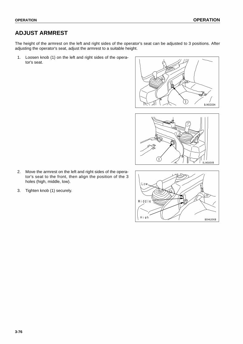
OPERATION OPERATION
3-76
ADJUST ARMREST
The height of the armrest on the left and right sides of the operator's seat can be adjusted to 3 positions. Afteradjusting the operator's seat, adjust the armrest to a suitable height.
1. Loosen knob (1) on the left and right sides of the opera-tor's seat.
2. Move the armrest on the left and right sides of the opera-tor's seat to the front, then align the position of the 3holes (high, middle, low).
3. Tighten knob (1) securely.
https://tractormanualz.com

OPERATION OPERATION
3-77
OPERATIONS AND CHECKS BEFORE STARTING ENGINE
WARNING● When starting the engine, check that the safety lock
lever is securely at the LOCK position.If the control levers are not locked and they aretouched by accident when starting the engine, thework equipment may move unexpectedly, and thismay lead to a serious injury or death.
● When standing up from the operator's seat, always setthe safety lock lever to the LOCK position, regardlessof whether the engine is running or stopped.
1. Check that parking lever (1) is locked. If this lever is notat the LOCK position, the engine will not start.If parking lever (1) is placed at the LOCK position, joy-stick (2) is returned to neutral even if it is at the FOR-WARD (REVERSE) position.
https://tractormanualz.com
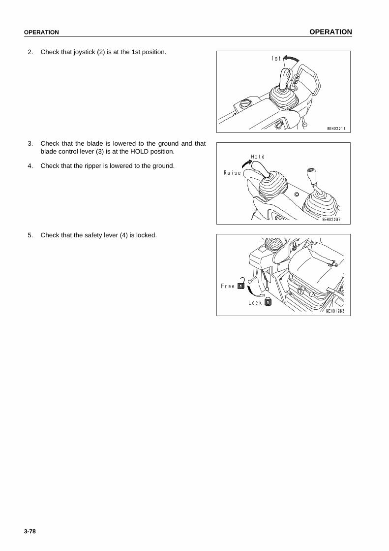
OPERATION OPERATION
3-78
2. Check that joystick (2) is at the 1st position.
3. Check that the blade is lowered to the ground and thatblade control lever (3) is at the HOLD position.
4. Check that the ripper is lowered to the ground.
5. Check that the safety lever (4) is locked.
https://tractormanualz.com

OPERATION OPERATION
3-79
STARTING ENGINE
NORMAL STARTING
WARNING● Check that there are no persons or obstacles in the
surrounding area, then sound the horn and start theengine.
● Exhaust gas is toxic. When starting the engine in con-fined spaces, be particularly careful to ensure goodventilation.
● Never use starting aid fluids as they may cause explo-sions.
NOTICE● Before starting the engine, check that the fuel control
dial is at the low idling (MIN) position.● Do not crank the starting motor continuously for more
than 20 seconds.If the engine does not start, wait for at least 2 minutesbefore trying again.
● If the fuel control dial is at the FULL position, theengine will accelerate suddenly and cause damage tothe engine parts, so set it to an intermediate or lowspeed position.
1. Set the fuel control dial to the low idling (MIN) position.
● If it is at the high idling (MAX) position, alwayschange it to the low idling (MIN) position.
2. Insert the key into starting switch (2) and turn the key tothe START position.The engine will start.
https://tractormanualz.com
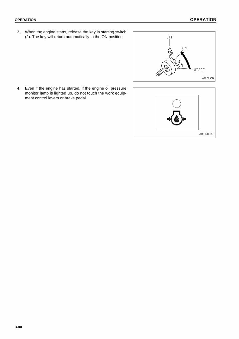
OPERATION OPERATION
3-80
3. When the engine starts, release the key in starting switch(2). The key will return automatically to the ON position.
4. Even if the engine has started, if the engine oil pressuremonitor lamp is lighted up, do not touch the work equip-ment control levers or brake pedal.
https://tractormanualz.com
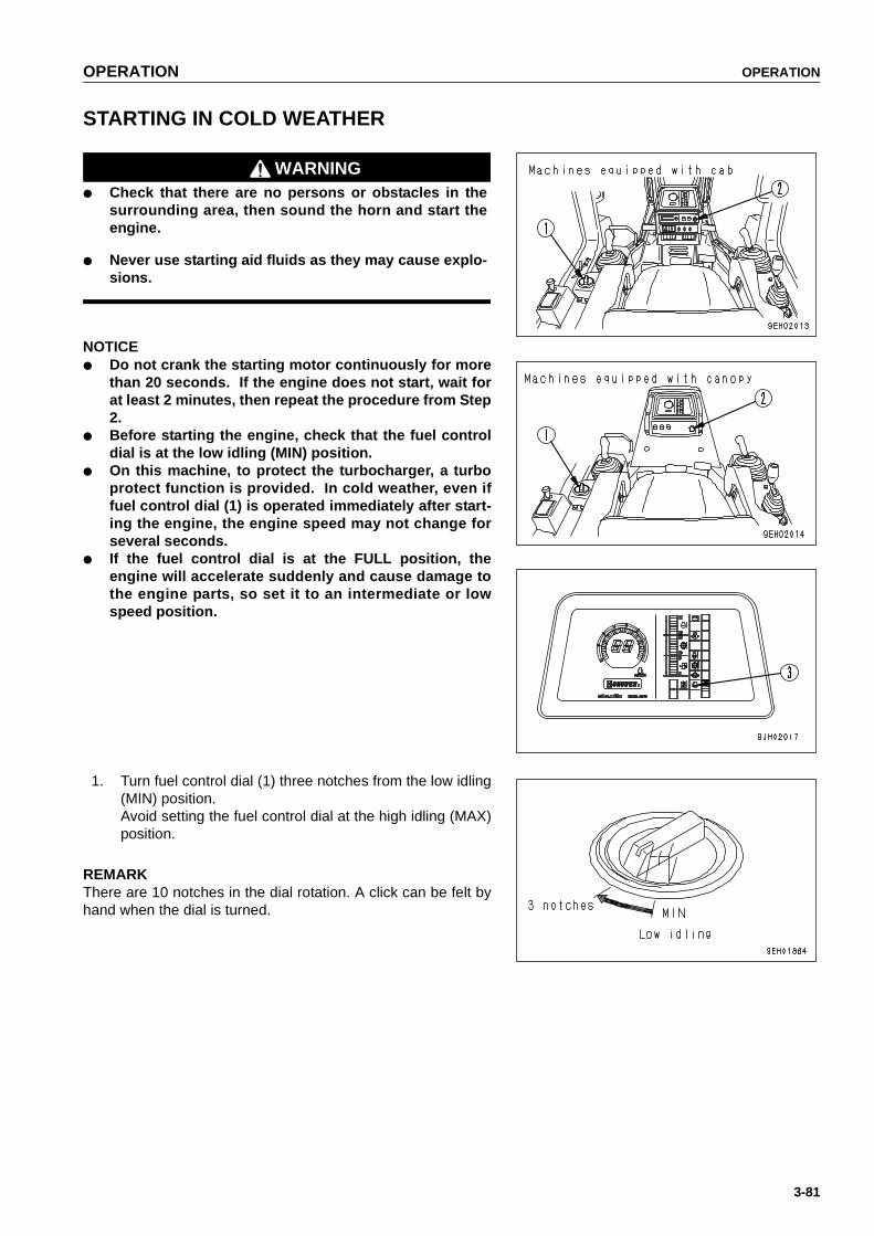
OPERATION OPERATION
3-81
STARTING IN COLD WEATHER
WARNING● Check that there are no persons or obstacles in the
surrounding area, then sound the horn and start theengine.
● Never use starting aid fluids as they may cause explo-sions.
NOTICE● Do not crank the starting motor continuously for more
than 20 seconds. If the engine does not start, wait forat least 2 minutes, then repeat the procedure from Step2.
● Before starting the engine, check that the fuel controldial is at the low idling (MIN) position.
● On this machine, to protect the turbocharger, a turboprotect function is provided. In cold weather, even iffuel control dial (1) is operated immediately after start-ing the engine, the engine speed may not change forseveral seconds.
● If the fuel control dial is at the FULL position, theengine will accelerate suddenly and cause damage tothe engine parts, so set it to an intermediate or lowspeed position.
1. Turn fuel control dial (1) three notches from the low idling(MIN) position.Avoid setting the fuel control dial at the high idling (MAX)position.
REMARKThere are 10 notches in the dial rotation. A click can be felt byhand when the dial is turned.
https://tractormanualz.com

OPERATION OPERATION
3-82
2. Insert the key into the starting switch (2) and turn the keyto the ON position.
● When the key is turned to the ON position, preheat-ing is automatically carried out according to theambient temperature (engine water temperature).The preheating pilot lamp (3) lights up during thepreheating operation.
REMARK● When the ambient temperature is higher than about -5ºC,
the automatic preheating is not actuated.● When the ambient temperature is lower than about -5ºC,
the preheating is automatically carried out for about 20 to40 seconds according to the ambient temperature.
3. Keep this state until the preheating pilot lamp (3) goesout.
REMARKWhen the ambient temperature is low, this lamp lights up for 36seconds and then the lamp switches to flashing.
4. When preheating pilot lamp (3) goes out, turn the key instarting switch (2) to the START position to start theengine. The time that preheating pilot lamp (3) stays onchanges according to the ambient temperature as shownin the table below.
REMARKRegardless of the ambient temperature, if the key in startingswitch (2) is turned from OFF position to left, preheating pilotlamp (3) will light up and preheating will start. (Preheating con-tinues while the starting switch is held at the left.)For the details of the preheating time, see the table in Step 4.
Ambient temperature Preheat time
-5ºC to -10ºC(23ºF to 14ºF)
20 to 27 seconds
-10ºC to -20ºC(14ºF to -4ºF)
27 to 40 seconds
-20ºC to -30ºC(-4ºF to -22ºF)
40 seconds
https://tractormanualz.com

OPERATION OPERATION
3-83
While preheating is being carried out, the preheating pilot lamp(3) lights up to show that preheating is being carried out. After itlights up for 36 seconds, it flashes for 16 seconds and goesout. When it goes out, complete the preheating immediately.
If the engine does not start with the above operation, wait forabout 2 minutes, and repeat steps from Step 2.
5. When the engine starts, release the key in starting switch(2). The key will return automatically to the ON position.
REMARKImmediately after starting the engine, run the engine at idling, and do not operate the decelerator pedal or workequipment during this time.
Guideline for idling time
● Cold weather: At least 15 seconds● When first starting engine after changing engine oil or replacing engine oil filter: 20 seconds
6. Even if the engine has started, if the engine oil pressuremonitor lamp is lighted up, do not touch the work equip-ment control levers or brake pedal.
REMARK● The actuation time for the turbo protect function and the relationship with the engine coolant temperature are
as shown below.If the fuel control dial is operated within the time shown below, the engine speed will not change.
Colling water temperature Turbo protect time (sec.)
+10ºC above(+50ºF above)
0
+10 to -10ºC(+50ºF to 14ºF)
Change 0 to 5
-10ºC below(14ºF below)
5
https://tractormanualz.com

OPERATION OPERATION
3-84
● In cold weather, the turbo protect function is actuated, so the engine speed is maintained below 1,000 rpm forseveral seconds. After that, it changes to the speed specified by the set position of fuel control dial.
https://tractormanualz.com
OPERATION OPERATION
3-85
AFTER STARTING ENGINE
After starting the engine, do not immediately start operations.First, carry out the following operations and checks.
WARNING● Emergency stop
If there has been any abnormal actuation or trouble, turn the starting switch key to the OFF position.
● If the work equipment is operated without warming the machine up sufficiently, the response of thework equipment to the movement of the control lever will be slow, and the work equipment may notmove as the operator desires, so always carry out the warming-up operation. Particularly in coldareas, be sure to carry out the warming-up operation fully.
BREAKING-IN THE NEW MACHINE
NOTICEBefore operating the machine for the first time, confirm that cooling water is in the radiator. If the machineis delivered without cooling water in the radiator, completely clean the inside of the radiator by flowingcity water through the radiator, then fill the radiator with cooling water.
CAUTIONYour Komatsu machine has been thoroughly adjusted and tested before shipment. However, operatingthe machine under severe conditions at the beginning can adversely affect the performance and shortenthe machine life.Be sure to breaking-in the machine for the initial 100 hours (as indicated by the service meter).During breaking-in operations, follow the precautions described in this manual.
● Run the engine at idling for 15 seconds after starting it. During this time, do not operate the control levers orfuel control dial.
● Idle the engine for 5 minutes after starting it up.
● Avoid operation with heavy loads or at high speeds.
● Avoid sudden starts, sudden acceleration, sudden steering and sudden stops except in cases of emergency.
https://tractormanualz.com

OPERATION OPERATION
3-86
WARMING-UP OPERATION
After starting the engine, do not immediately start operations.First, carry out the following operations and checks.
NOTICEAvoid abrupt acceleration until warm-up run is completed.Do not run the engine at low idling or high idling for morethan 20 minutes. If it is necessary to run the engine atidling, apply a load or run at a medium speed from time totime.
https://tractormanualz.com

OPERATION OPERATION
3-87
1. Turn fuel control dial (1) to the center position betweenLOW IDLING (MIN) and HIGH IDLING (MAX) and run theengine at medium speed for about 5 minutes with noload.
2. After warm-up run is completed, check gauges and cau-tion lamps for proper operation. If any abnormality isfound, repair it.Check that each lamp does not light up.
● Battery charge lamp (3)● Engine oil pressure caution lamp (4) ● Engine water temperature caution lamp (5)● Power train oil temperature caution lamp (6)● HSS charge pressure caution lamp (7)● HSS oil temperature caution lamp (8)
3. Continue to run the engine at light load until the greenrange of the engine water temperature gauge (2) lights.
4. Check that there is no abnormal exhaust gas color, noise, or vibration. If any abnormality is found, repair it.
https://tractormanualz.com

OPERATION OPERATION
3-88
IN COLD AREAS
After starting the engine, do not immediately start operations.First, carry out the following operations and checks.
NOTICEAvoid abrupt acceleration until warm-up run is completed.Do not run the engine at low idling or high idling for morethan 20 minutes. If it is necessary to run the engine atidling, apply a load or run at a medium speed from time totime.
1. Turn fuel control dial (1) to the center position betweenLOW IDLING (MIN) and HIGH IDLING (MAX) and run theengine at medium speed for about 5 minutes with noload.
https://tractormanualz.com

OPERATION OPERATION
3-89
2. Operate blade control lever (9) to the RAISE position,then keep the blade raised to the maximum height andcontinue to relieve the circuit for 10 minutes.
3. Finally, operate blade control lever (9) and ripper controllever (10) to operate all the blade and ripper cylindersseveral times.If the oil temperature in the work equipment is not prop-erly raised, there will be a time lag in the response of thework equipment and steering.
4. After warm-up run is completed, check gauges and cau-tion lamps for proper operation. If any abnormality isfound, repair it. Check that each lamp does not light up.
● Battery charge lamp (3)● Engine oil pressure caution lamp (4) ● Engine water temperature caution lamp (5)● Power train oil temperature caution lamp (6)● HSS charge pressure caution lamp (7)● HSS oil temperature caution lamp (8)
5. Continue to run the engine at light load until the greenrange of the engine water temperature gauge (2) lights.
REMARKIf the oil temperature in the power train is not raised properly, itwill take longer to accelerate to the maximum speed.
6. Check that there is no abnormal exhaust gas color, noise,or vibration. If any abnormality is found,repair it.
https://tractormanualz.com

OPERATION OPERATION
3-90
STOPPING ENGINE
NOTICEIf the engine is abruptly stopped before it has cooleddown, engine life may be greatly shortened. Consequently,do not abruptly stop the engine apart from an emergency.In particular, if the engine has overheated, do not abruptlystop it but run it at medium speed to allow it to cool gradu-ally, then stop it.
1. Turn fuel control dial (1) to the low idling position and runthe engine at low idling speed for about 5 minutes toallow it to gradually cool down.
2. Turn the key in starting switch (2) to OFF position andstop the engine.
3. Remove the key from starting switch (2).
https://tractormanualz.com

OPERATION OPERATION
3-91
CHECK AFTER STOPPING ENGINE
1. Walk around the machine and check the work equipment, machine exterior, and undercarriage, and checkalso for leakage of oil or water. If any abnormalities are found, repair them.
2. Fill the fuel tank.
3. Check the engine compartment for paper and debris. Clean out any paper and debris to avoid a fire hazard.
4. Remove any mud affixed to the undercarriage.
https://tractormanualz.com

OPERATION OPERATION
3-92
MACHINE OPERATION
MOVING MACHINE OFF
WARNING● When moving machine, check that the area around
the machine is safe, and sound the horn before mov-ing.Clear all personnel from the machine and the area.Clear all obstacles from the path of the machine.Use extreme care when reversing the machine. Notethere is an blind spot behind the machine.
● When starting on slopes, always keep brake pedal (2)depressed even after releasing parking lever (1).
● When starting the machine up a steep slope, turn fuelcontrol dial (7) to the full speed (MAX) position to setthe engine to full speed. Then keep brake pedal (2)depressed, pull joystick (3) to the 1st speed position,operate joystick (3) in the direction of travel, thenrelease brake pedal (2) slowly to allow the machine tostart gradually.When the machine starts, release the brake pedalcompletely.
1. Set parking lever (1) to the FREE position.
https://tractormanualz.com

OPERATION OPERATION
3-93
2. Set joystick (3) to the desired position.
3. Set safety lever (6) for blade control lever (4) and rippercontrol lever (5) to the FREE position.
4. Operate blade control lever (4) and ripper control lever(5) to the RAISE position, raise the blade 40 - 50 cm(15.8 - 19.7 in) from the ground, and raise the ripper tothe maximum height.
5. Turn fuel control dial (7) to the full speed (MAX) position,raise the engine speed, and fully depress deceleratorpedal (8).
6. Move joystick (3) to the F (FORWARD) or R (REVERSE)position, gradually release the decelerator pedal (8) andallow the machine to move off.
https://tractormanualz.com

OPERATION OPERATION
3-94
STOPPING MACHINE
WARNING● Avoid stopping suddenly. Give yourself ample room
when stopping.
● When stopping the machine, select flat hard groundand avoid dangerous places. If it is unavoidably nec-essary to park the machine on a slope, place the park-ing lever in the LOCK position and insert blocksunderneath the track shoes. As an additional safetymeasure, thrust the work equipment into the ground.
● If the work equipment control lever is touched by acci-dent, the work equipment may move suddenly, andthis may lead to a serious injury or death. Before leav-ing the operator's seat, always operate the safetylever to place it securely at the LOCK position.
1. Depress brake pedal (1) to stop the machine.
NOTICEIf the brake is depressed when the engine speed or travelspeed is high, the brake disc may make a slipping sound.Normally, depress decelerator pedal (3) to reduce theengine speed and travel speed before depressing thebrake.
2. Place joystick (2) at the neutral position and set thespeed range to 1st.
https://tractormanualz.com

OPERATION OPERATION
3-95
SHIFTING GEAR
It is possible to change the speed range when traveling, sothere is no need to stop the machine when shifting gear.
1. Move joystick (1) to the desired gear position to shiftgears.
Gear shiftingRotate the joystick 30º to carry out gear shifting operation.
Position (A): 1stPosition (B): 2ndPosition (C): 3rd
For details of the maximum speed at each speed range, see"SPECIFICATIONS (PAGE 5-2)".
https://tractormanualz.com

OPERATION OPERATION
3-96
REMARKWhen gear shifting operation is carried out, the display panelwill display the used speed range.
NEUTRAL 1st: N1 is displayed on the display panelFORWARD 2nd: F2 is displayed on the display panelREVERSE 3rd: R3 is displayed on the display panel
SHIFTING BETWEEN FORWARD AND REVERSE
CAUTIONThere is no need to stop the machine even when switch-ing between FORWARD and REVERSE.To increase safety, operator comfort,and the life of thetransmission, do not carry out switching operations withthe engine running at full speed. Always depress thedecelerator pedal to lower the engine speed.
1. Depress decelerator pedal (2) and reduce the enginespeed.
https://tractormanualz.com

OPERATION OPERATION
3-97
2. Return joystick (1) to the neutral position, reduce thespeed, then depress brake pedal (3) and stop themachine.
3. After depressing decelerator pedal (2), move joystick (1)to the desired position.
4. Release decelerator pedal (2) to raise the engine speed.
https://tractormanualz.com

OPERATION OPERATION
3-98
STEERING MACHINE
WARNING● Avoid as much as possible turning the machine on a slope.
The machine will tend to slip sideways.Particular care should be taken on soft or clay land.
● Never make a pivot turn at high speed.
NORMAL TURNING
WARNINGThe feeling of the operation if the operator carries out acounterrotation turn when your head is facing the rear isdifferent from the feeling when facing the front, so nevercarry out counterrotation turns when facing the rear.
To turn the machine while traveling, incline joystick (1) in thedirection to turn.
https://tractormanualz.com
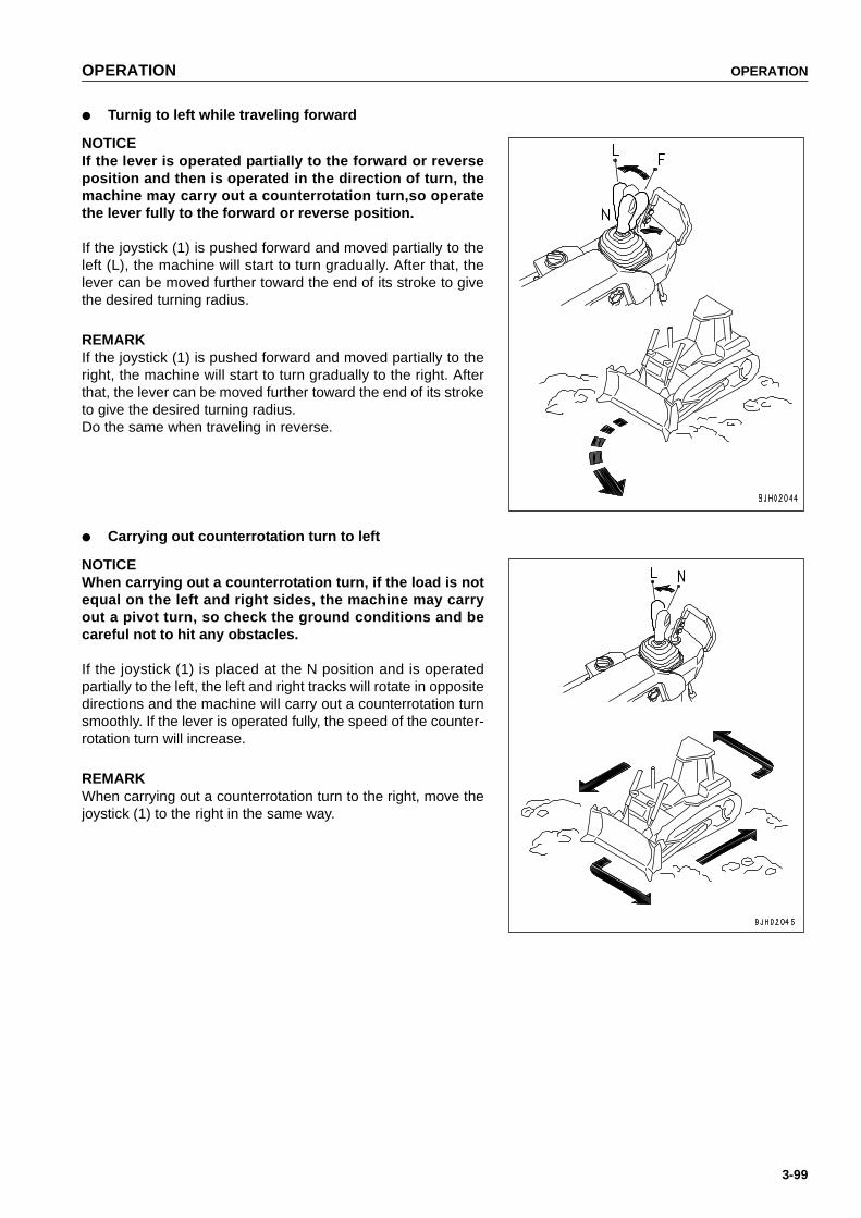
OPERATION OPERATION
3-99
● Turnig to left while traveling forward
NOTICEIf the lever is operated partially to the forward or reverseposition and then is operated in the direction of turn, themachine may carry out a counterrotation turn,so operatethe lever fully to the forward or reverse position.
If the joystick (1) is pushed forward and moved partially to theleft (L), the machine will start to turn gradually. After that, thelever can be moved further toward the end of its stroke to givethe desired turning radius.
REMARKIf the joystick (1) is pushed forward and moved partially to theright, the machine will start to turn gradually to the right. Afterthat, the lever can be moved further toward the end of its stroketo give the desired turning radius.Do the same when traveling in reverse.
● Carrying out counterrotation turn to left
NOTICEWhen carrying out a counterrotation turn, if the load is notequal on the left and right sides, the machine may carryout a pivot turn, so check the ground conditions and becareful not to hit any obstacles.
If the joystick (1) is placed at the N position and is operatedpartially to the left, the left and right tracks will rotate in oppositedirections and the machine will carry out a counterrotation turnsmoothly. If the lever is operated fully, the speed of the counter-rotation turn will increase.
REMARKWhen carrying out a counterrotation turn to the right, move thejoystick (1) to the right in the same way.
https://tractormanualz.com

OPERATION OPERATION
3-100
TURNING WHILE DESCENDING A SLOPE
With machines that can carry out counterrotation turns, on steep downhill slopes where the machine may travelunder its own weight, or on downhill slopes where it is being pushed by a towed machine, the machine will notsteer in the opposite direction, so do as follows.
NOTICEDo not use the counterrotation turn on slopes. The load on the left and right sides will not be uniform, andthe machine may turn sharply to one side.
● Making gradual turns to left while traveling forwardIf the joystick (1) is pushed forward and moved partially tothe left (L), the machine turns gradually to the left. (Doesnot become reverse steering)
REMARKWhen making gradual turns to the right, push the joystick (1)forward, and move it partially to the right. (Does not becomereverse steering)Do the same when traveling in reverse.
https://tractormanualz.com

OPERATION OPERATION
3-101
PRECAUTIONS FOR OPERATION
PERMISSIBLE WATER DEPTH
When operating in water, always keep center line (1) of theidler above the surface of the water.Also, be careful that the engine cooling fan will not come incontact with water. The fan can be damaged.
PAY ATTENTION TO GAUGES
When the red range lights up on the transmission oil temperature gauge while operating, reduce load and wait forlowering of temperature.
PRECAUTIONS WHEN TRAVELING UP OR DOWN HILLS
Method of using decelerator pedal
When stepping on the decelerator pedal while going uphill, climbing ability will be reduced and the machine willstop. Furthermore, the engine sometimes will stall.
Use engine as brake
Do not move the joystick to the N position.When traveling down hills of more than 15º, shift down to 1st speed (R1 or F1).
Braking when traveling downhill
While descending a slope using the engine as a brake, also apply the brakes.Failure to brake may result in overrunning, causing engine trouble.
PRECAUTIONS ON SLOPES
Be careful of fuel level
If the fuel level in the fuel tank becomes low when working on slopes, the engine may suck in air because of theangle of the machine or the swaying of the machine. If this makes the engine stop, the braking effect will bereduced, so be careful not to let the fuel level in the fuel tank become too low.
Precautions when engine stops on slopes
If the engine stops while working or traveling on a hill, the brake is automatically applied, move the parking lever tothe LOCK position to apply the parking brake.
https://tractormanualz.com
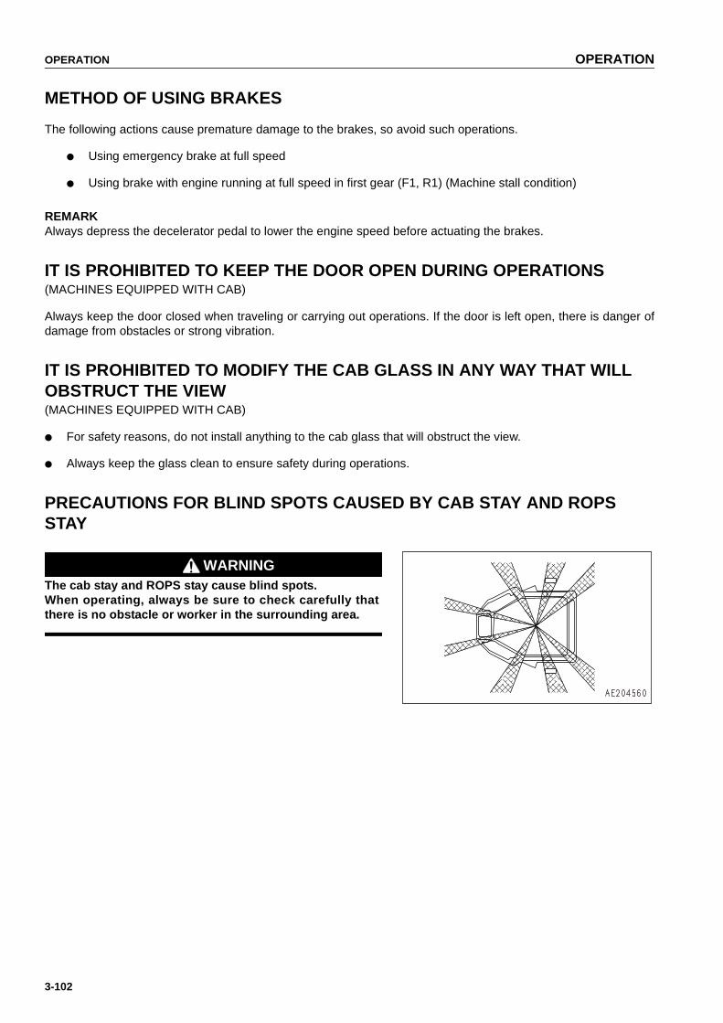
OPERATION OPERATION
3-102
METHOD OF USING BRAKES
The following actions cause premature damage to the brakes, so avoid such operations.
● Using emergency brake at full speed
● Using brake with engine running at full speed in first gear (F1, R1) (Machine stall condition)
REMARKAlways depress the decelerator pedal to lower the engine speed before actuating the brakes.
IT IS PROHIBITED TO KEEP THE DOOR OPEN DURING OPERATIONS(MACHINES EQUIPPED WITH CAB)
Always keep the door closed when traveling or carrying out operations. If the door is left open, there is danger ofdamage from obstacles or strong vibration.
IT IS PROHIBITED TO MODIFY THE CAB GLASS IN ANY WAY THAT WILL OBSTRUCT THE VIEW(MACHINES EQUIPPED WITH CAB)
● For safety reasons, do not install anything to the cab glass that will obstruct the view.
● Always keep the glass clean to ensure safety during operations.
PRECAUTIONS FOR BLIND SPOTS CAUSED BY CAB STAY AND ROPS STAY
WARNINGThe cab stay and ROPS stay cause blind spots.When operating, always be sure to check carefully thatthere is no obstacle or worker in the surrounding area.
https://tractormanualz.com

OPERATION OPERATION
3-103
PARKING MACHINE
WARNING● Avoid stopping suddenly. Give yourself ample room
when stopping.
● When stopping the machine, select flat hard groundand avoid dangerous places. If it is unavoidably nec-essary to park the machine on a slope, place the park-ing lever in the LOCK position and insert blocksunderneath the track shoes. As an additional safetymeasure, thrust the work equipment into the ground.
● If the work equipment control lever is touched by acci-dent, the work equipment may move suddenly, andthis may lead to a serious injury or death. Before leav-ing the operator's seat, always operate the safetylever to place it securely at the LOCK position.
1. Depress brake pedal (1) to stop the machine.
NOTICEIf the brake is depressed when the engine speed or travelspeed is high, the brake disc may make a slipping sound.Normally, depress decelerator pedal (3) to reduce theengine speed and travel speed before depressing thebrake.
https://tractormanualz.com

OPERATION OPERATION
3-104
2. Place joystick (2) in NEUTRAL position and set thespeed range to 1st.
3. Operate parking lever (4) to lock the brakes.
4. Operate blade control lever (5) and ripper control lever(6) to the LOWER position, and lower the blade and rip-per to the ground.
5. Set blade control lever (5) and ripper control lever (6) tothe HOLD position.
6. Lock blade control lever (5) and ripper control lever (6)with safety lever (7).
https://tractormanualz.com

OPERATION OPERATION
3-105
CHECK AFTER FINISHING WORK
1. Use the meters and caution lamps to check the enginewater temperature, engine oil pressure, fuel level, powertrain oil temperature gauge, charge lamp, HSS charge oilpressure and HSS oil temperature.
LOCKING
To prevent vandalism, there are locks at the following places.Places that can be locked with the starting switch key.
● Right and left engine side cover (1)
● Battery inspection cover (2)
● Inspection cover for fuel tank drain valve (3) (option)
● Cab door opener (4) (machines equipped with cab)
● Cap with lock (5) (option)
● Radiator cap
● Fuel tank cap
● Hydraulic oil tank cap
● Hydraulic oil tank breather
● Power train oil filler cap
● Top cover of hood at cab front (air conditioner filter cover)(6)
https://tractormanualz.com

OPERATION OPERATION
3-106
RIPPER OPERATION
EFFECTIVE METHOD OF USE
● The optimum digging angle for the shank is when theshank is perpendicular to the ground (ripping angle:45º -50º).
● In comparatively soft rock (seismic velocity:1200 m/s orbelow), it is also possible to carry out ripping with the shanktilted to the rear (max.ripping angle).
● On comparatively hard rock, if ripping is carried out withthe shank tilted to the rear, there will be excessive wear ofthe point of tip (A), and the self-sharpening ability will belost.
● During ripping operations, if the shoes slip because ofboulders or resistance from the bedrock, use the tilt cylin-der.
● Choosing a suitable ripper point to match the type of rock isone of the most important elements in using the rippereffectively.Ripper points are available for different types of rock, soselect the most suitable ripper point from the list. Fordetails, see "PROCEDURE FOR SELECTING RIPPERPOINT (PAGE 6-8)".
DIGGING UP BOULDERS OR ROCKBED
During ripper operations, if stubborn boulders or rockbed causethe tracks to slip or the travel speed to become slower, operatethe tilt cylinder to dig up the boulder/rockbed.
https://tractormanualz.com
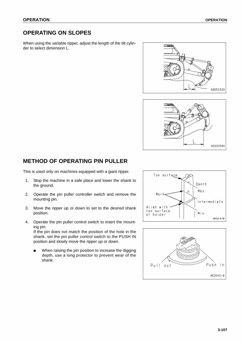
OPERATION OPERATION
3-107
OPERATING ON SLOPES
When using the variable ripper, adjust the length of the tilt cylin-der to select dimension L.
METHOD OF OPERATING PIN PULLER
This is used only on machines equipped with a giant ripper.
1. Stop the machine in a safe place and lower the shank tothe ground.
2. Operate the pin puller controller switch and remove themounting pin.
3. Move the ripper up or down to set to the desired shankposition.
4. Operate the pin puller control switch to insert the mount-ing pin.If the pin does not match the position of the hole in theshank, set the pin puller control switch to the PUSH INposition and slowly move the ripper up or down.
● When raising the pin position to increase the diggingdepth, use a long protector to prevent wear of theshank.
https://tractormanualz.com
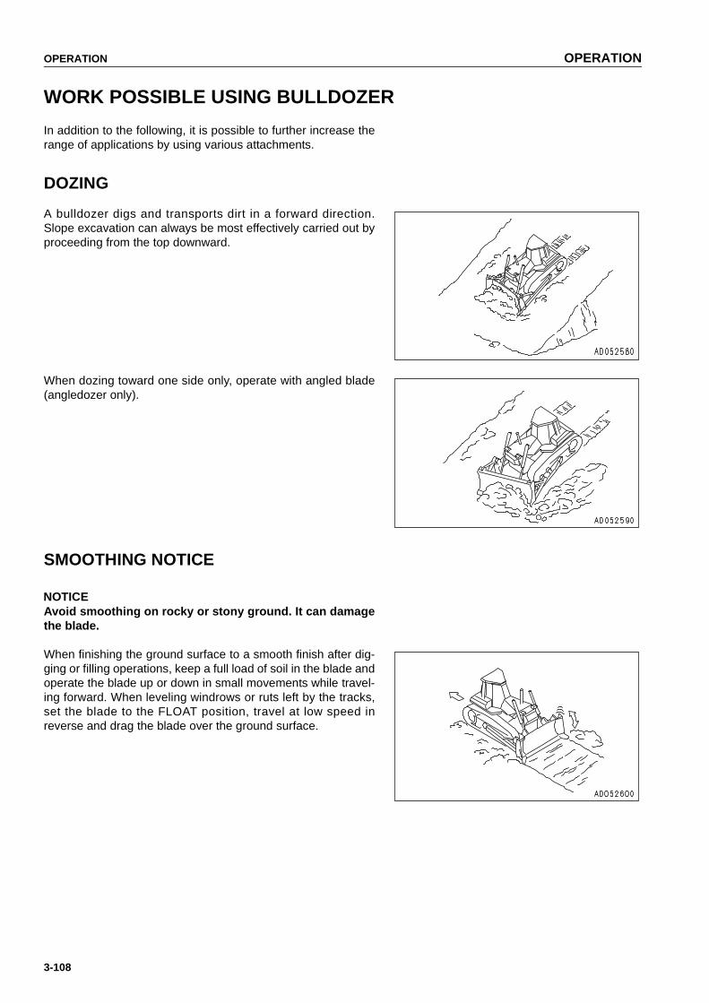
OPERATION OPERATION
3-108
WORK POSSIBLE USING BULLDOZER
In addition to the following, it is possible to further increase therange of applications by using various attachments.
DOZING
A bulldozer digs and transports dirt in a forward direction.Slope excavation can always be most effectively carried out byproceeding from the top downward.
When dozing toward one side only, operate with angled blade(angledozer only).
SMOOTHING NOTICE
NOTICEAvoid smoothing on rocky or stony ground. It can damagethe blade.
When finishing the ground surface to a smooth finish after dig-ging or filling operations, keep a full load of soil in the blade andoperate the blade up or down in small movements while travel-ing forward. When leveling windrows or ruts left by the tracks,set the blade to the FLOAT position, travel at low speed inreverse and drag the blade over the ground surface.
https://tractormanualz.com

OPERATION OPERATION
3-109
CUTTING INTO HARD OR FROZEN GROUND OR DITCHING
For digging and ditch excavation of hard or frozen ground, tiltthe blade. Even hard ground can be dug effectively by a tiltedblade.
FELLING TREES, REMOVING STUMPS
NOTICEDo not up root trees or stumps by angling or tilting theblade.
For trees with a diameter of 10-30 cm (3.9-11.8 in), raise theblade high and push 2 or 3 times to fell the tree.Next, travel in reverse, and dig the corner of the blade into theground to cut and dig up the roots.When doing this, never hit the tree at high speed or applyshock to fell the tree.
PUSHER OPERATIONS
NOTICE● When carrying out pusher operations, always install a
pusher plate.● When approaching other machine,vdepress the decel-
erator pedal or reduce the travel speed with the fuelcontrol dial and bring the machines gently into con-tact. When in contact, raise the engine speed graduallyand push with full power.
https://tractormanualz.com
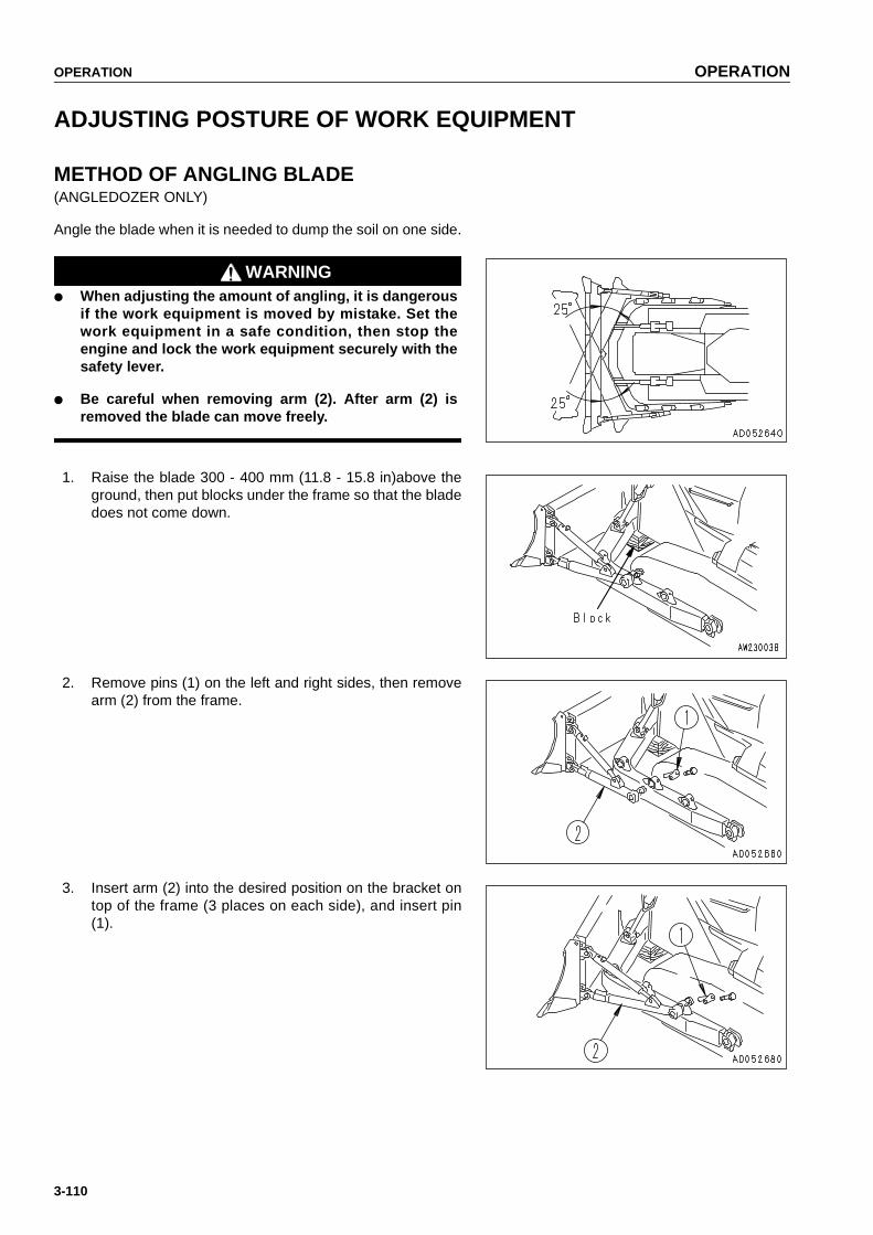
OPERATION OPERATION
3-110
ADJUSTING POSTURE OF WORK EQUIPMENT
METHOD OF ANGLING BLADE(ANGLEDOZER ONLY)
Angle the blade when it is needed to dump the soil on one side.
WARNING● When adjusting the amount of angling, it is dangerous
if the work equipment is moved by mistake. Set thework equipment in a safe condition, then stop theengine and lock the work equipment securely with thesafety lever.
● Be careful when removing arm (2). After arm (2) isremoved the blade can move freely.
1. Raise the blade 300 - 400 mm (11.8 - 15.8 in)above theground, then put blocks under the frame so that the bladedoes not come down.
2. Remove pins (1) on the left and right sides, then removearm (2) from the frame.
3. Insert arm (2) into the desired position on the bracket ontop of the frame (3 places on each side), and insert pin(1).
https://tractormanualz.com

OPERATION OPERATION
3-111
REMARKWhen assembling an angle dozer to the C-frame, adjust theclearance of the center joint by adjusting the length of arm (2)and brace (3) so that dimension S of center joint (4) is 20 mm(0.8 in).
ADJUSTING TILT AMOUNT(ANGLEDOZER, POWER TILTDOZER, POWER TILT POWER PITCHDOZER)
WARNINGWhen adjusting the amount of tilt, it is dangerous if the work equipment is moved by mistake. Set thework equipment in a safe condition,then stop the engine and lock the work equipment securely with thesafety lever.
AngledozerNOTICEThe maximum amount of tilt is 400 mm (15.8 in).Be sure not to exceed 400 mm (15.8 in)for the tilt.
https://tractormanualz.com

OPERATION OPERATION
3-112
1. Raise the blade 300 - 400 mm (11.8 - 15.8 in)above theground, then put blocks under the frame so that the bladedoes not come down.
2. Loosen set bolt (1) of the brace, insert a suitable bar intohole (2) of the brace, and turn it.
REMARKWhen rotating the brace with the adjustment bar, carry out theoperation with the blade raised from the ground.
Right tilt: Make right side shorter, left side longerLeft tilt: Make left side shorter, right side longer
3. Tighten set bolt (1).
NOTICEThe standard value for distance between the brace jointsis 1493 mm (58.8 in),but adjust so that the maximum tiltdoes not exceed 400 mm (15.8 in). Do not use if the tiltexceeds 400 mm (15.8 in) as this will cause strain on vari-ous parts.
Power tiltdozer
NOTICEThe maximum tilt amount is 1000 mm (39.4 in). Be sure notto exceed this value.
1. A tilt of approx.500 mm (19.7 in)can be obtained by oper-ating the blade control lever.
https://tractormanualz.com

OPERATION OPERATION
3-113
2. If a greater tilt amount is needed,use adjustment bar (2)installed to left brace (1) to rotate brace (1) and changethe brace length.It is possible to tilt to a maximum of 1000 mm (39.4 in).
REMARKWhen adjusting the tilt in Steps 1 and 2, carry out the operationwith the blade raised from the ground.
NOTICEThe standard value for distance ( ) between the joints is1389 mm (54.7 in), but adjust the brace length so that themaximum tilt does not exceed 1000 mm (39.4 in). Do notuse if the tilt exceeds 1000 mm (39.4 in) as this will causestrain on various parts.
https://tractormanualz.com

OPERATION OPERATION
3-114
ADJUSTING RIPPER
ADJUSTING DIGGING DEPTH
Mounting pin holes are provided in the shank and these are used according to the desired digging depth. For nor-mal use, use the bottom hole, and when particularly deep digging is needed, use the top hole.
To change the digging depth, do as follows.
1. Place a pointed object on the tip of pin (1), then hit with ahammer to remove from the opposite side.
2. Remove pin (2) and change the position of the shankhole.
3. Insert pin (1) partially by hand then knock it in with a ham-mer.
● Insert pin partially by hand to align the holes thenknock it in with a hammer.
● When a giant ripper is installed, use the pin puller.For details, see "METHOD OF OPERATING PINPULLER (PAGE 3-107)".
REPLACING POINT AND PROTECTOR
To protect the shank, if the protector and point installed to thetip are worn, replace them.Place a pin remover on the pin marked by the arrow, then hitwith a hammer to remove from the opposite side.
https://tractormanualz.com

OPERATION OPERATION
3-115
If the wear exceeds the wear limit in the table below, replacethe worn parts.
ADJUST ANGLE OF BLADE EDGE(ANGLEDOZER, POWER TILTDOZER, POWER TILT POWER PITCHDOZER)
WARNINGIt is dangerous if the work equipment moves by mistake when adjusting angle of the blade edge. Set thework equipment in a stable condition, then stop the engine and apply the locks securely to the safetylever.
Adjust the angle (θ) of the blade edge to match the type of soil.
Angledozer
Adjust the cutting angle by changing the distance ( ) betweenthe joints so that the length of the brace is the same on the leftand right sides.
INCREASE distance ( ) to INCREASE angle (θ)DECREASE distance ( ) to DECREASE angle (θ).
The standard for the cutting angle (θ) is 54º.
The standard for the distance ( ) between the joints is 1493mm (58.8 in).
Unit:mm (in)
Basic dimension Wear limit
(1) Point 335 (13.2) 225 (10.0)
(2) Protector 115 (4.5) 90 (3.5)
https://tractormanualz.com

OPERATION OPERATION
3-116
Power tiltdozer
Turn the brace with bar handle (1) to change the distance ( )between the joints to change the cutting angle (θ) as follows.
INCREASE distance ( ) to INCREASE angle (θ)DECREASE distance ( ) to DECREASE angle (θ).
The standard for the cutting angle (θ) is 52º.
The standard for the distance ( ) between the joints is 1389mm (54.7 in).
https://tractormanualz.com
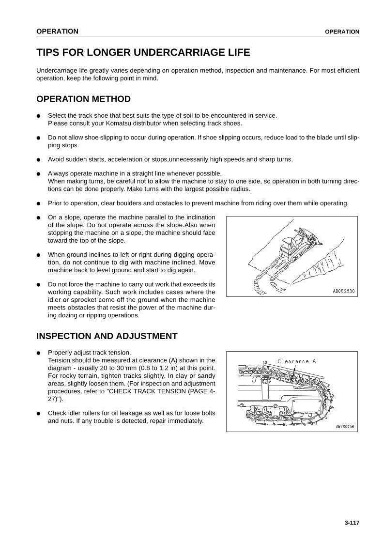
OPERATION OPERATION
3-117
TIPS FOR LONGER UNDERCARRIAGE LIFE
Undercarriage life greatly varies depending on operation method, inspection and maintenance. For most efficientoperation, keep the following point in mind.
OPERATION METHOD
● Select the track shoe that best suits the type of soil to be encountered in service.Please consult your Komatsu distributor when selecting track shoes.
● Do not allow shoe slipping to occur during operation. If shoe slipping occurs, reduce load to the blade until slip-ping stops.
● Avoid sudden starts, acceleration or stops,unnecessarily high speeds and sharp turns.
● Always operate machine in a straight line whenever possible.When making turns, be careful not to allow the machine to stay to one side, so operation in both turning direc-tions can be done properly. Make turns with the largest possible radius.
● Prior to operation, clear boulders and obstacles to prevent machine from riding over them while operating.
● On a slope, operate the machine parallel to the inclinationof the slope. Do not operate across the slope.Also whenstopping the machine on a slope, the machine should facetoward the top of the slope.
● When ground inclines to left or right during digging opera-tion, do not continue to dig with machine inclined. Movemachine back to level ground and start to dig again.
● Do not force the machine to carry out work that exceeds itsworking capability. Such work includes cases where theidler or sprocket come off the ground when the machinemeets obstacles that resist the power of the machine dur-ing dozing or ripping operations.
INSPECTION AND ADJUSTMENT
● Properly adjust track tension.Tension should be measured at clearance (A) shown in thediagram - usually 20 to 30 mm (0.8 to 1.2 in) at this point.For rocky terrain, tighten tracks slightly. In clay or sandyareas, slightly loosen them. (For inspection and adjustmentprocedures, refer to "CHECK TRACK TENSION (PAGE 4-27)").
● Check idler rollers for oil leakage as well as for loose boltsand nuts. If any trouble is detected, repair immediately.
https://tractormanualz.com
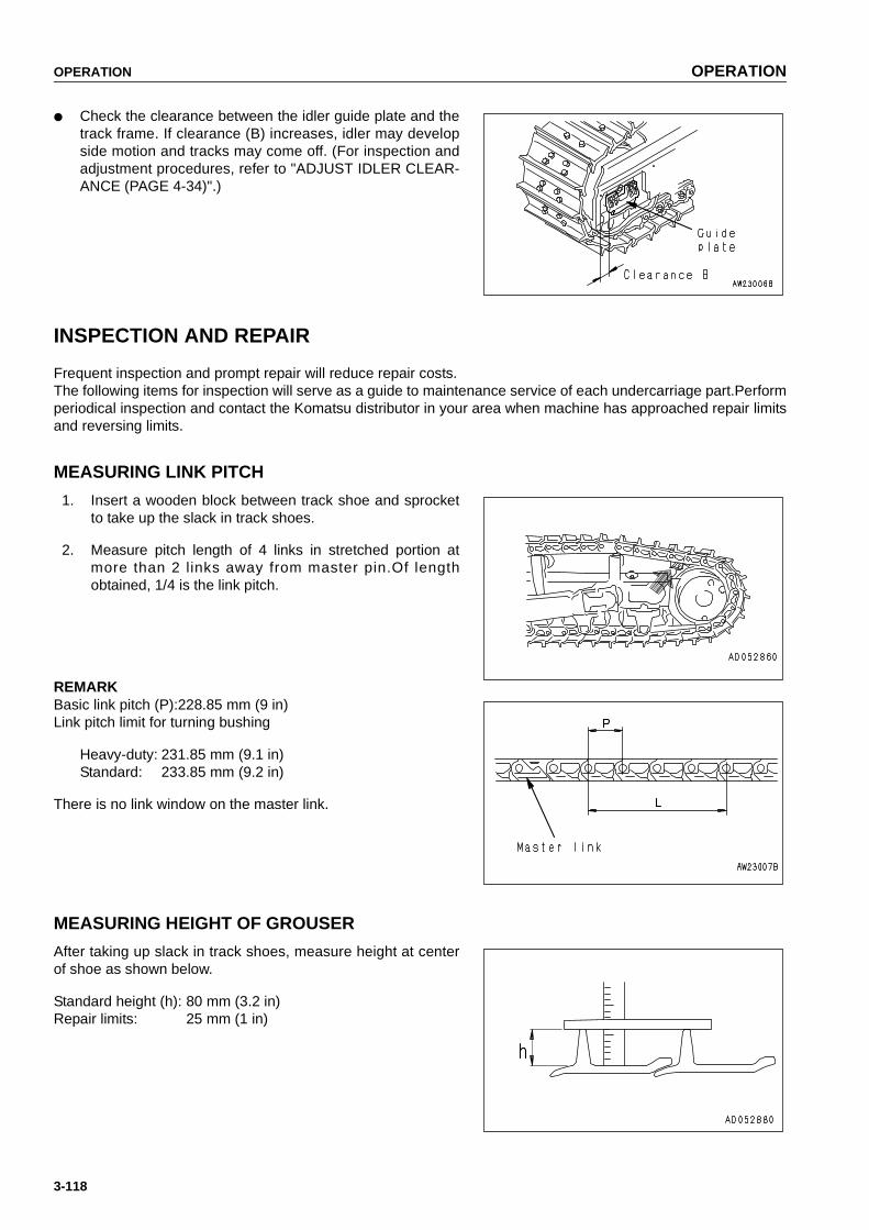
OPERATION OPERATION
3-118
● Check the clearance between the idler guide plate and thetrack frame. If clearance (B) increases, idler may developside motion and tracks may come off. (For inspection andadjustment procedures, refer to "ADJUST IDLER CLEAR-ANCE (PAGE 4-34)".)
INSPECTION AND REPAIR
Frequent inspection and prompt repair will reduce repair costs.The following items for inspection will serve as a guide to maintenance service of each undercarriage part.Performperiodical inspection and contact the Komatsu distributor in your area when machine has approached repair limitsand reversing limits.
MEASURING LINK PITCH
1. Insert a wooden block between track shoe and sprocketto take up the slack in track shoes.
2. Measure pitch length of 4 links in stretched portion atmore than 2 links away from master pin.Of lengthobtained, 1/4 is the link pitch.
REMARKBasic link pitch (P):228.85 mm (9 in)Link pitch limit for turning bushing
Heavy-duty: 231.85 mm (9.1 in)Standard: 233.85 mm (9.2 in)
There is no link window on the master link.
MEASURING HEIGHT OF GROUSER
After taking up slack in track shoes, measure height at centerof shoe as shown below.
Standard height (h): 80 mm (3.2 in)Repair limits: 25 mm (1 in)
https://tractormanualz.com

OPERATION OPERATION
3-119
MEASURING OUTSIDE DIAMETER OF TRACK ROLLER
1. Measure height (size C) of link tread as shown.
2. Stop machine at position where link tread, whose size Chas been measured, completely contacts roller tread.Then measure size B.
3. Calculate outside diameter of tread (size A):A = (B - C) x 2
Standard size (A): 250 mm (9.9 in)Repair limits: 210 mm (8.3 in)
https://tractormanualz.com
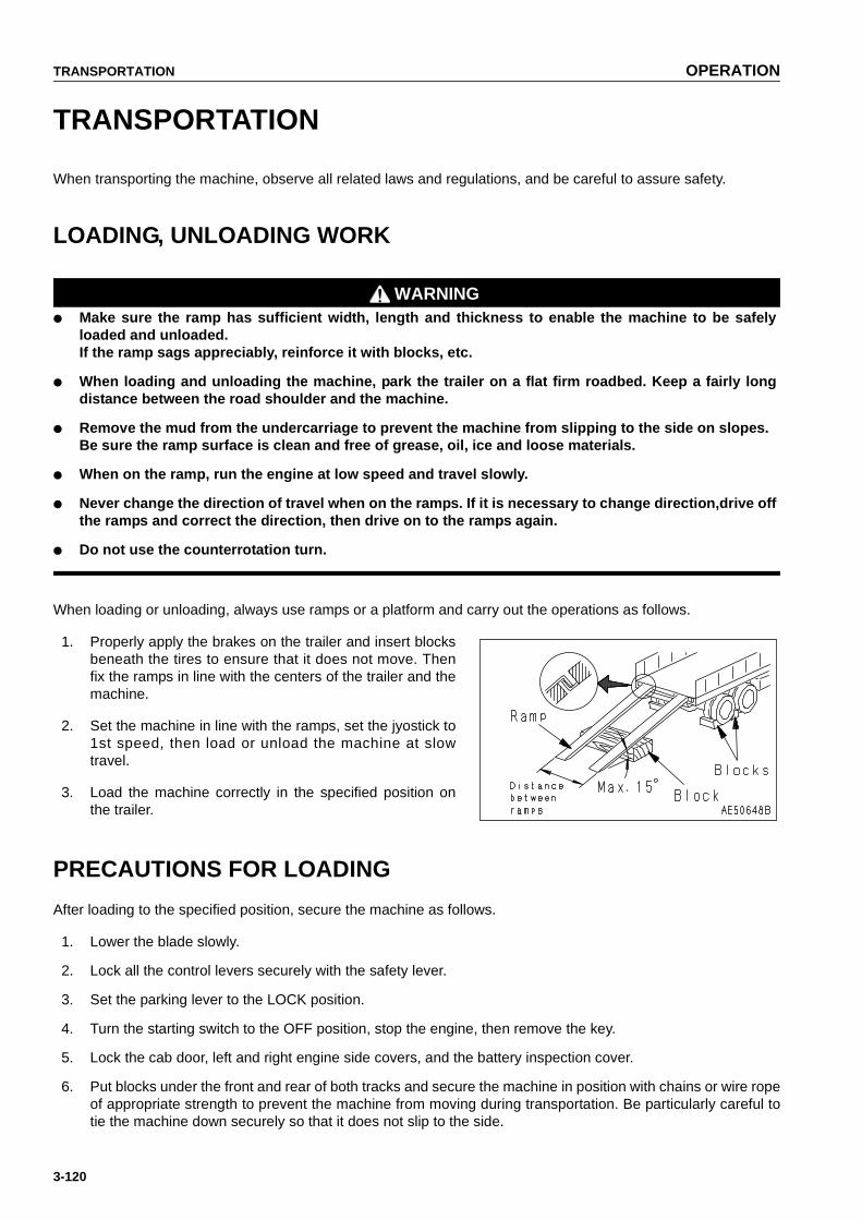
TRANSPORTATION OPERATION
3-120
TRANSPORTATION
When transporting the machine, observe all related laws and regulations, and be careful to assure safety.
LOADING, UNLOADING WORK
WARNING● Make sure the ramp has sufficient width, length and thickness to enable the machine to be safely
loaded and unloaded.If the ramp sags appreciably, reinforce it with blocks, etc.
● When loading and unloading the machine, park the trailer on a flat firm roadbed. Keep a fairly longdistance between the road shoulder and the machine.
● Remove the mud from the undercarriage to prevent the machine from slipping to the side on slopes.Be sure the ramp surface is clean and free of grease, oil, ice and loose materials.
● When on the ramp, run the engine at low speed and travel slowly.
● Never change the direction of travel when on the ramps. If it is necessary to change direction,drive offthe ramps and correct the direction, then drive on to the ramps again.
● Do not use the counterrotation turn.
When loading or unloading, always use ramps or a platform and carry out the operations as follows.
1. Properly apply the brakes on the trailer and insert blocksbeneath the tires to ensure that it does not move. Thenfix the ramps in line with the centers of the trailer and themachine.
2. Set the machine in line with the ramps, set the jyostick to1st speed, then load or unload the machine at slowtravel.
3. Load the machine correctly in the specified position onthe trailer.
PRECAUTIONS FOR LOADING
After loading to the specified position, secure the machine as follows.
1. Lower the blade slowly.
2. Lock all the control levers securely with the safety lever.
3. Set the parking lever to the LOCK position.
4. Turn the starting switch to the OFF position, stop the engine, then remove the key.
5. Lock the cab door, left and right engine side covers, and the battery inspection cover.
6. Put blocks under the front and rear of both tracks and secure the machine in position with chains or wire ropeof appropriate strength to prevent the machine from moving during transportation. Be particularly careful totie the machine down securely so that it does not slip to the side.
https://tractormanualz.com

OPERATION TRANSPORTATION
3-121
METHOD OF LIFTING MACHINE
WARNING● Never raise the machine with any worker on it.
● Always make sure that the wire rope used for lifting the machine is of ample strength for the weight ofthe machine.
● Never try to lift the machine in any posture other than the posture given in the procedure below. Thereis danger that the machine may lose its balance.
● When lifting the machine, pay attention to the center of gravity and be careful to maintain the balance.
When lifting the machine, carry out the operation as follows on flat ground.
1. Stop the engine and be sure to set the parking lever to the LOCK position.
2. Set the lifting position for the machine as shown in thediagram on the right.
NOTICEThis description of the method for lifting the chassisapplies to standard specification machines.Depending on the attachments and options installed, themethod of lifting will differ. In such cases, please contactyour Komatsu distributor for advice.
For details of the weight, see "SPECIFICATIONS (PAGE 5-2)".
https://tractormanualz.com

TRANSPORTATION OPERATION
3-122
PRECAUTIONS FOR TRANSPORTATION
WARNINGDetermine the route for transporting the machine by taking into account the width, height and weight ofthe machine.
Obey all state and local laws governing the weight, width and length of a load. Observe all regulations governingwide loads.
Method of transportation
https://tractormanualz.com
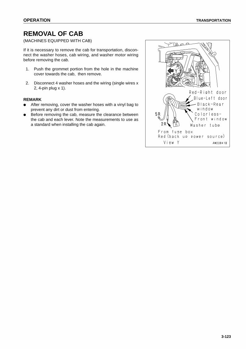
OPERATION TRANSPORTATION
3-123
REMOVAL OF CAB(MACHINES EQUIPPED WITH CAB)
If it is necessary to remove the cab for transportation, discon-nect the washer hoses, cab wiring, and washer motor wiringbefore removing the cab.
1. Push the grommet portion from the hole in the machinecover towards the cab, then remove.
2. Disconnect 4 washer hoses and the wiring (single wires x2, 4-pin plug x 1).
REMARK● After removing, cover the washer hoses with a vinyl bag to
prevent any dirt or dust from entering.● Before removing the cab, measure the clearance between
the cab and each lever. Note the measurements to use asa standard when installing the cab again.
https://tractormanualz.com
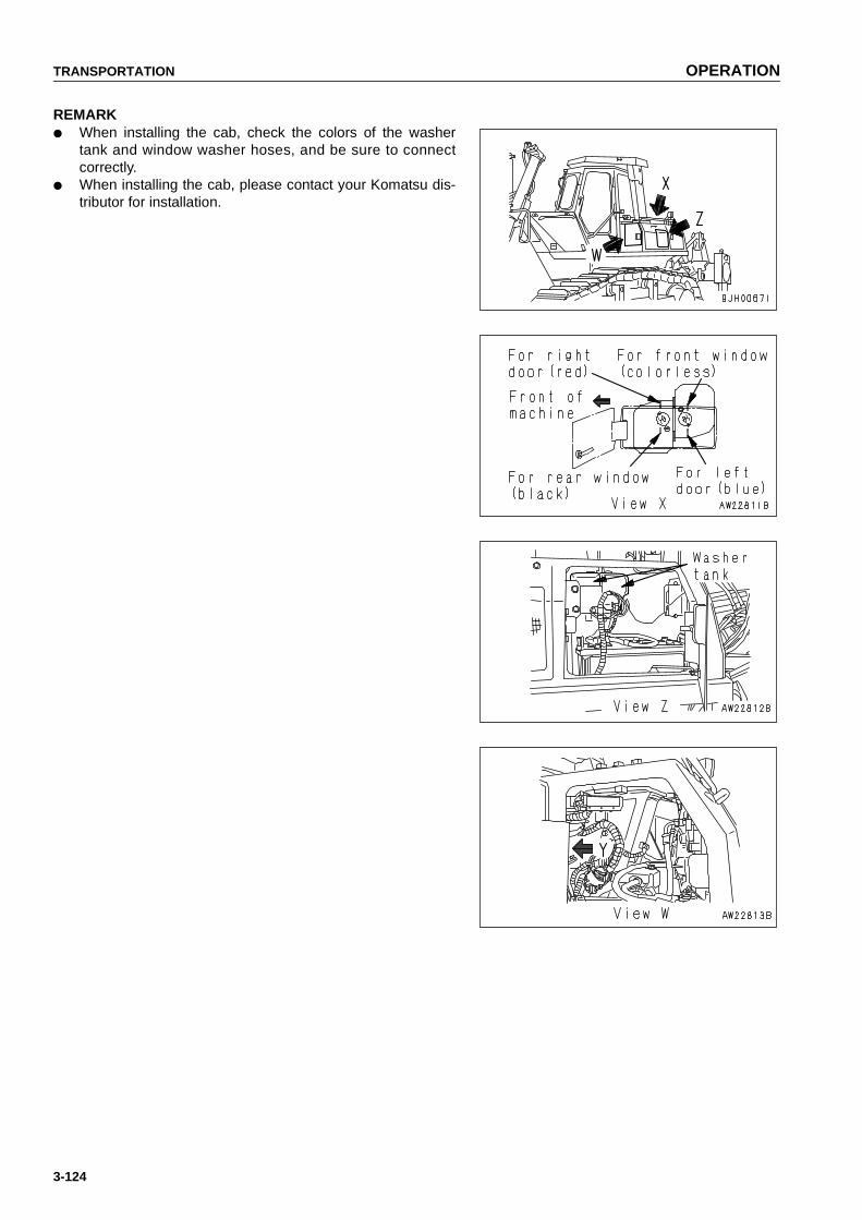
TRANSPORTATION OPERATION
3-124
REMARK● When installing the cab, check the colors of the washer
tank and window washer hoses, and be sure to connectcorrectly.
● When installing the cab, please contact your Komatsu dis-tributor for installation.
https://tractormanualz.com

OPERATION COLD WEATHER OPERATION
3-125
COLD WEATHER OPERATION
COLD WEATHER OPERATION INFORMATION
If the temperature becomes low, it becomes difficult to start the engine, and the coolant may freeze, so do as fol-lows.
FUEL AND LUBRICANTS
Change to fuel and oil with low viscosity for all components. For details of the specified viscosity, see "USE OFFUEL, COOLANT AND LUBRICANTS ACCORDING TO AMBIENT TEMPERATURE (PAGE 4-11)".
COOLING SYSTEM COOLANT
WARNING● Antifreeze is toxic. Be careful not to get it into your eyes or on your skin. If it should get into your eyes
or on your skin, wash it off with large quantities of fresh water and see a doctor at once.
● Antifreeze is toxic. Be extremely careful when handling it. When replacing coolant containing anti-freeze or when handling coolant when repairing the radiator, contact your Komatsu distributor or askyour local antifreeze dealer. Be careful not to let the water flow into drainage ditches or spray on tothe ground surface.
● Antifreeze is flammable, so do not bring any flame close. Do not smoke when handling antifreeze.
NOTICE● Never use methanol, ethanol or propanol based antifreeze.● Absolutely avoid using any water leak preventing agent irrespective of weather it is used indepen-
dently or mixed with an antifreeze.● Do not mix one antifreeze with a different brand.
For details of the antifreeze mixture when changing the coolant, see "CLEAN INSIDE OF COOLING SYSTEM(PAGE 4-22)".
REMARKWhere no permanent antifreeze is available, an ethylene glycol antifreeze without corrosion inhibitor may be usedonly for the cold season. In this case, clean the cooling system twice a year (in spring and autumn). When refillingthe cooling system, add antifreeze in autumn, but do not add any in spring.
For details of the antifreeze mixture when changing the coolant, see "CLEAN INSIDE OF COOLING SYSTEM(PAGE 4-22)".
https://tractormanualz.com

COLD WEATHER OPERATION OPERATION
3-126
BATTERY
WARNING● The battery generates flammable gas, so do not bring fire or sparks near the battery.
● Battery electrolyte is dangerous. If it gets in your eyes or on your skin, wash it off with large amountof water, and consult a doctor.
● Battery electrolyte dissolves paint. If it gets on to the bodywork, wash it off immediately with water.
● If the battery electrolyte is frozen, do not charge the battery or start the engine with a different powersource. There is danger that the battery may explode.
When the ambient temperature drops, the capacity of the battery will also drop. If the battery charge ratio is low,the battery electrolyte may freeze. Maintain the battery charge as close as possible to 100%, and insulate itagainst cold temperature so that the machine can be started easily the next morning.
REMARKMeasure the specific gravity and calculate the rate of charge from the following conversion table.
● As the battery capacity drops markedly in low temperatures, cover the battery or remove it from the machine,keep it in a warm place, and install it again the next morning.
● If the electrolyte level is low, add distilled water in the morning before beginning work. Do not add the waterafter the day's work so as to prevent fluid in the battery from freezing in the night.
Temp. of fluid 20ºC(68ºF)
0ºC(32ºF)
-10ºC(14ºF)
-20ºC(-4ºF)Rate of charge
100 1.28 1.29 1.30 1.31
90 1.26 1.27 1.28 1.29
80 1.24 1.25 1.26 1.27
75 1.23 1.24 1.25 1.26
https://tractormanualz.com
OPERATION COLD WEATHER OPERATION
3-127
AFTER DAILY WORK COMPLETION
WARNING● Performing idle-running of the tracks is dangerous, so stay well away from the tracks.
● After completion of operations, fill the fuel tank to prevent the formation of water caused by conden-sation of moisture in the empty space in the tank when the temperature goes down.
To prevent mud, water, or the undercarriage from freezing and making it impossible for the machine to move onthe following morning, always observe the following precautions.
● Mud and water on the machine body should be completely removed. This is to prevent damage to the sealcaused by mud or dirt getting inside the seal with frozen drops of water.
● Park the machine on hard, dry ground.
If this is impossible, park the machine on wooden boards.
The boards help protect the tracks from being frozen in soil and the machine can start next morning.
● Open the drain valve and drain any water collected in the fuel system to prevent it from freezing.
● After operation in water or mud, remove water from undercarriage as described below to extend undercarriageservice life.
AFTER COLD WEATHER SEASON
When season changes and the weather becomes warmer, do as follows.
● Replace the fuel and oil for all parts with oil of the viscosity specified.
For details, see "USE OF FUEL, COOLANT AND LUBRICANTS ACCORDING TO AMBIENTTEMPERATURE (PAGE 4-11)".
● If for any reason permanent antifreeze cannot be used, and an ethyl glycol base antifreeze (winter, one sea-son type) is used instead, or if no antifreeze is used, drain the cooling system completely, then clean out theinside of the cooling system thoroughly, and fill with fresh soft water.
https://tractormanualz.com

LONG TERM STORAGE OPERATION
3-128
LONG TERM STORAGE
BEFORE STORAGE
When putting the machine in storage for a long time, do as follows.
● Clean and wash all parts, then store the machine indoors. If the machine has to be stored outdoors, selectlevel ground and cover the machine with a sheet.
● Completely fill the fuel tank, lubricate and change the oil before storage.
● Apply a thin coat of grease to the metal surface of the hydraulic piston rods.
● Disconnect the negative terminals of the battery and cover it or remove it from the machine and store it sepa-rately.
● If the ambient temperature is expected to drop below 0ºC (32ºF), always add antifreeze to the cooling water.
● Place all control levers at the neutral position, set the safety lever and parking brake lever to the LOCK posi-tion, and set the fuel control lever to the low idling position.
DURING STORAGE
WARNINGIf it is unavoidably necessary to carry out the rust-preventive operation while the machine is indoors,open the doors and windows to improve ventilation and prevent gas poisoning.
● During storage, always operate the machine once a month so that a new film of oil will be coated over mov-able parts and component surfaces. At the same time, also charge the battery.
● For machines equipped with an air conditioner, run the air conditioner.
● Rotate the tracks.
AFTER STORAGE
NOTICEIf the machine is to be used when the monthly rust prevention operation has not been carried out, pleasecontact your Komatsu distributor.
When using the machine after long-term storage, do as follows before using it.
● Wipe off all the grease coating the hydraulic cylinder rods.
● Add oil and grease to all places.
● When the machine has been stored for a long time, the moisture in the atmosphere will get into the oil. Checkthe oil at all parts before and after starting the engine. If there is water in the oil, change all the oil.
https://tractormanualz.com

OPERATION TROUBLESHOOTING
3-129
TROUBLESHOOTING
AFTER RUNNING OUT OF FUEL
WARNINGWhen air bleed plug (2) at the top of the fuel filter head or supply pump air breather (4) are removed, thesystem is still under pressure, so fuel may spurt out. Loosen these parts slowly before opening them.
When starting after running out of fuel, fill the filter cartridge with fuel and bleed the air from the fuel system beforestarting.
Procedure for Bleeding Air
1. Remove the fuel filter cartridge, fill the filter case with fuel, then install again.
NOTICE● The common rail fuel injection system used on this
machine consists of more precise parts than the con-ventional injection pump and nozzle, so problems maybe caused by dust or dirt getting in. When carrying outinspection or maintenance of the fuel system, paymore attention than normal to the entry of dirt. If dirt isstuck to any part, use fuel to wash it off completely.
● When filling with fuel, use clean fuel and be careful notto let any dust or dirt get in. Portion (B) at the center isthe clean side, so be particularly careful not to let anydust or dirt get in.
● When adding fuel, always add from small hole (A) ateight places on the dirty side.
● If no clean fuel is available, bleed the air with priming pump (3) without removing the fuel cartridge.
2. Loosen air bleed plug (2) at the top of the fuel filter headand open fuel supply valve (1) at the bottom of the fueltank.
3. Loosen the knob of priming pump (3), pump the knob,and check that fuel comes out from air bleed plug (2).After checking, tighten the plug.Tightening torque: 7.8 to 9.8 N•m (0.8 to 1 kgf•m, 5.8 to7.2 lbft)
https://tractormanualz.com
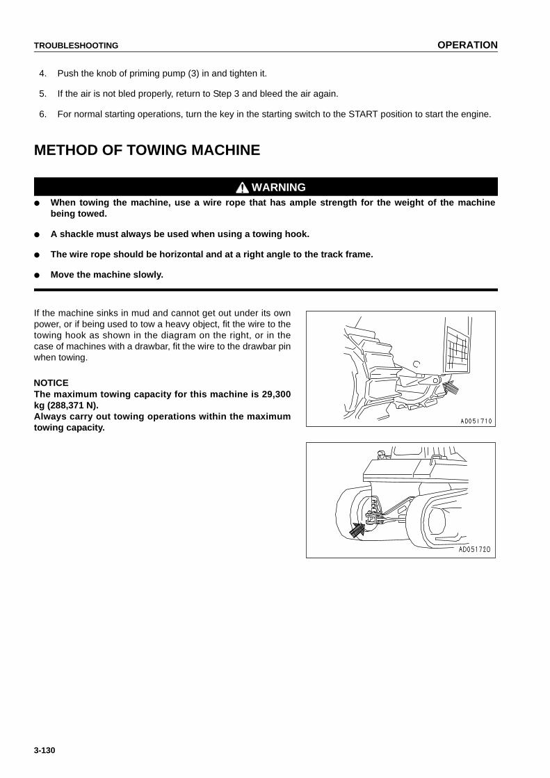
TROUBLESHOOTING OPERATION
3-130
4. Push the knob of priming pump (3) in and tighten it.
5. If the air is not bled properly, return to Step 3 and bleed the air again.
6. For normal starting operations, turn the key in the starting switch to the START position to start the engine.
METHOD OF TOWING MACHINE
WARNING● When towing the machine, use a wire rope that has ample strength for the weight of the machine
being towed.
● A shackle must always be used when using a towing hook.
● The wire rope should be horizontal and at a right angle to the track frame.
● Move the machine slowly.
If the machine sinks in mud and cannot get out under its ownpower, or if being used to tow a heavy object, fit the wire to thetowing hook as shown in the diagram on the right, or in thecase of machines with a drawbar, fit the wire to the drawbar pinwhen towing.
NOTICEThe maximum towing capacity for this machine is 29,300kg (288,371 N).Always carry out towing operations within the maximumtowing capacity.
https://tractormanualz.com

OPERATION TROUBLESHOOTING
3-131
DISCHARGED BATTERY
WARNING● It is dangerous to charge the battery while it is still
mounted on the machine. Always remove the batterybefore charging it.
● When checking or handling the battery, stop theengine and turn the starting switch key to the OFFposition.
● The battery generates hydrogen gas, so there is a haz-ard of explosion.Do not bring lighted cigarettes near the battery, or doanything that will cause sparks.
● Battery electrolyte is dilute sulphuric acid, and it willattack your clothes and skin. If it gets on your clothesor on your skin, wash it immediately off with largeamount of water. If it gets in your eyes, wash it outwith fresh water, and consult a doctor.
● When handling batteries, always wear protective gog-gles and rubber gloves.
● When removing the battery, first disconnect the cablefrom the ground (normally the negative (-) terminal).When installing, install the positive (+) terminal first.If a tool touches the positive terminal and the chassis,there is danger that it will cause a spark, so beextremely careful.
● If the terminals are loose, there is danger that thedefective contact may generate sparks that will causean explosion.
● When installing the terminals, install them tightly.When removing or installing the terminals, checkwhich is the positive (+) terminal and which is the neg-ative (-) terminal.
● Green rust around the terminals is a cause of self-dis-charge of the battery. Polish the terminals with sand-paper. After removing the rust, coat the terminalsthinly with grease before installing.
https://tractormanualz.com

TROUBLESHOOTING OPERATION
3-132
REMOVAL AND INSTALLATION OF BATTERY
NOTICEAfter fixing the battery in position, check that it does not move. If it moves, install it again.
● When removing, remove from the ground side first (normally the negative (-) terminal).Be careful not to touch between the (+) terminal and the machine with any tool. Letting a tool touch is danger-ous as it causes sparks.
● When installing, connect the ground side last.
● When replacing the battery, fix the battery securely with the battery mount clamp.
● Tightening torque of mounting bolts: 9.8 to 14.7 N•m {1 to 1.5 kgf•m, 7.2 to 10.8 lbft}
BATTERY CHARGES
When charging the battery, there is danger that the battery mayexplode if it is handled wrongly, so follow the instructions in"OTHER TROUBLE (PAGE 3-135)" and the instruction manualsupplied with the charger, and be sure to observe the followingprecautions.
● Set the voltage of the charger to match the voltage of thebattery to be charged. If the voltage is not selected cor-rectly, the charger may overheat and cause an explosion.
● Connect the positive (+) charger clip of the charger to thepositive (+) terminal of the battery, then connect the nega-tive (-) charger clip of the charger to the negative (-) termi-nal of the battery. Be sure to fix the clips securely.
● Set the charging current to 1/10 of the value of the rated battery capacity; when carrying out rapid charging,set it to less than the rated battery capacity.If the charger current is too high, the electrolyte will leak or dry up, and this may cause the battery to catch fireand explode.
● If the battery electrolyte is frozen, do not charge the battery or start the engine with a different power source.There is a hazard that this will ignite the battery electrolyte and cause the battery to explode.
● Do not use or charge the battery if the battery electrolyte level is below the LOWER LEVEL line. This maycause an explosion. Always check the battery electrolyte level periodically and add distilled water to bring theelectrolyte level to the UPPER LEVEL line.
https://tractormanualz.com

OPERATION TROUBLESHOOTING
3-133
STARTING ENGINE WITH BOOSTER CABLES
When starting the engine with a booster cable, do as follows:
REMOVAL, INSTALLATION OF BATTERY CABLE
1. Open battery cover (1) and (2).
2. Before removing the battery, remove the ground cable(normally connected to the negative (-) terminal). If anytool touches between the positive terminal and the chas-sis, there is danger of sparks being generated. Loosenthe nut of the terminal and remove the wires from the bat-tery.
3. When installoing the battery, connect the ground cablelast.Insert the hole of the terminal on the battery and tightenthe nut.Tightening torque: 9.8 to 19.6 Nm (1.0 to 2.0 kgm, 7.2 to14.5 lbft)
4. Install battery cover (1) and (2).
CONNECTING AND DISCONNECTING BOOSTER CABLES
WARNING● When connecting the cables, never contact the posi-
tive (+) and negative (-) terminals.
● When starting the engine with a booster cable, alwayswear safety glasses.
● Be careful not to let the normal machine and problemmachine contact each other. This prevents sparksfrom generating near the battery which could ignitethe hydrogen gas given off by the battery. If hydrogengas explodes, it could cause serious injury.
● Make sure that there is no mistake in the boostercable connections.The final connection is to the engine block, but sparkswill be generated when this is done, so connect to aplace as far as possible from the battery. (However,avoid connecting the cable to the work equipment, asconduction is poor.)
● Use care when removing the cables from the machinethat has been started. To avoid hydrogen explosion,do not allow the cable ends to contact each other orthe machine.
NOTICE● The starting system for this machine uses 24 V. For the normal machine, also use a 24V battery.● The size of the booster cable and clip should be suitable for the battry size.● The battry of the normal machine must be the same capacity as that of the engine to be started.● Check the cables and clips for damage or corrosion.
https://tractormanualz.com

TROUBLESHOOTING OPERATION
3-134
● Make sure that the cables and clips are firmly connected.● Check that the safety lock levers and parking brake levers of both machine are in the LOCK position.● Check that each lever is in the NEUTRAL position.
BOOSTER CABLE CONNECTION
Keep the starting switch of the nornal machine and problemmachine both at the OFF position.
Connect the booster cable as follows, in the order of the num-bers marked in the diagram.
1. Make sure that the starting switches of the normalmachine and problem machine are both at the OFF posi-tion.
2. Connect one clip of booster cable (A) to the positive (+)terminal of the problem machine.
3. Connect the other clip of booster cable (A) to the positive (+) terminal of the normal machine.
4. Connect one clip of booster cable (B) to the negative (-) terminal of the normal machine.
5. Connect the other clip of booster cable (B) to the engine block of the problem machine.
STARTING THE ENGINE
CAUTIONAlways check that the safety lock lever is set to the LOCK position, regardless of whether the machine isworking normally or has failed. Check also that all the control levers are at the HOLD or NEUTRAL posi-tion.
1. Make sure the clips are firmly connected to the battery terminals.
2. Start the engine of the normal machine and keep it to run at high idling speed.
3. Turn the starting switch of the problem machine to the START position and start the engine. If the enginedoesn't start at first, try again after 2 minutes or so.
BOOSTER CABLE DISCONNECTION
After the engine has started, disconnect the booster cables inthe reverse of the order in which they were connected.
1. Remove one clip of booster cable (B) from the engineblock of the problem machine.
2. Remove the other clip of booster cable (B) from the nega-tive (-) terminal of the normal machine.
3. Remove one clip of booster cable (A) from the positive(+) terminal of the normal machine.
4. Remove the other clip of booster cable (A) from the posi-tive (+) terminal of the problem machine.
https://tractormanualz.com
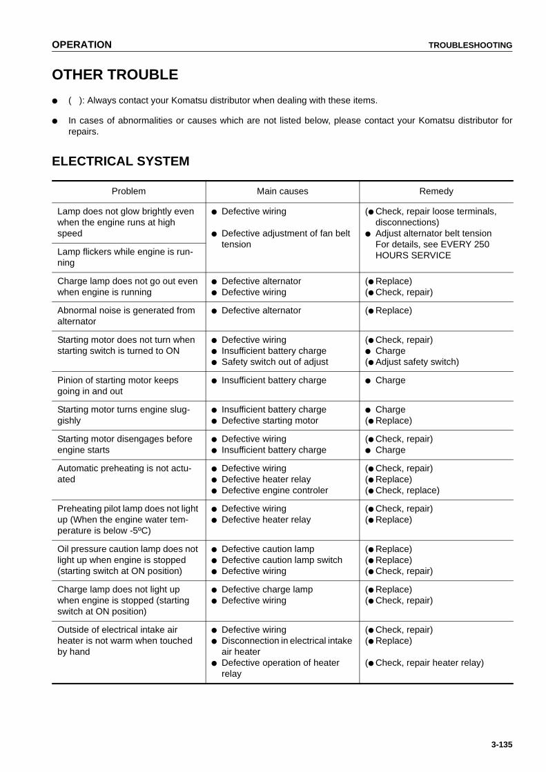
OPERATION TROUBLESHOOTING
3-135
OTHER TROUBLE
● ( ): Always contact your Komatsu distributor when dealing with these items.
● In cases of abnormalities or causes which are not listed below, please contact your Komatsu distributor forrepairs.
ELECTRICAL SYSTEM
Problem Main causes Remedy
Lamp does not glow brightly even when the engine runs at high speed
● Defective wiring
● Defective adjustment of fan belt tension
(● Check, repair loose terminals, disconnections)
● Adjust alternator belt tensionFor details, see EVERY 250HOURS SERVICELamp flickers while engine is run-
ning
Charge lamp does not go out even when engine is running
● Defective alternator● Defective wiring
(● Replace)(● Check, repair)
Abnormal noise is generated from alternator
● Defective alternator (● Replace)
Starting motor does not turn when starting switch is turned to ON
● Defective wiring● Insufficient battery charge● Safety switch out of adjust
(● Check, repair)● Charge(● Adjust safety switch)
Pinion of starting motor keeps going in and out
● Insufficient battery charge ● Charge
Starting motor turns engine slug-gishly
● Insufficient battery charge● Defective starting motor
● Charge(● Replace)
Starting motor disengages before engine starts
● Defective wiring● Insufficient battery charge
(● Check, repair)● Charge
Automatic preheating is not actu-ated
● Defective wiring ● Defective heater relay● Defective engine controler
(● Check, repair)(● Replace)(● Check, replace)
Preheating pilot lamp does not light up (When the engine water tem-perature is below -5ºC)
● Defective wiring● Defective heater relay
(● Check, repair)(● Replace)
Oil pressure caution lamp does not light up when engine is stopped (starting switch at ON position)
● Defective caution lamp● Defective caution lamp switch● Defective wiring
(● Replace)(● Replace)(● Check, repair)
Charge lamp does not light up when engine is stopped (starting switch at ON position)
● Defective charge lamp● Defective wiring
(● Replace)(● Check, repair)
Outside of electrical intake air heater is not warm when touched by hand
● Defective wiring● Disconnection in electrical intake
air heater● Defective operation of heater
relay
(● Check, repair)(● Replace)
(● Check, repair heater relay)
https://tractormanualz.com

TROUBLESHOOTING OPERATION
3-136
Problem Main causes Remedy
Air conditioner does not work prop-erly
● Blown fuse● Insufficient battery charge● Defective air conditioner switch● Defective blower switch● Defective compressor
(● Check, repair)● Charge(● Replace air conditioner switch)(● Replace blower switch)(● Replace)
HSS charge pressure caution lamp does not light up when starting switch is turned ON.
● Defective caution lamp● Defective wiring● Defective charge pressure sen-
sor
(● Replace)(● Check, repair)(● Replace)
https://tractormanualz.com

OPERATION TROUBLESHOOTING
3-137
MONITOR RELATED
If an abnormality code is displayed on the service meter dis-play, take the necessary action according to the table below.
Abnormality code
AbnormalityMethod of displaying
abnormalityRemedy
E01 ● Abnormality in backup alarm relay
● Abnormality in sensor for displaying engine speed on monitor panel
● Abnormality in buzzer can-cel switch
Abnormality code and service hour are displayed in turn on service meter portion
The automatic functions stop and some functions stop, but it is still possible to carry out operations. Please contact your Komatsu distributor immediately for repairs.
E02 ● Abnormality in water tem-perature sensor
● Abnormality in HSS control function of power distribu-tion
Abnormality code and service hour are displayed in turn on service meter portion, caution lamp flashes, buzzer sounds
If user stops engine and then starts again, operations are possible without limit func-tions. However, user must be careful. Please contact your Komatsu distributor immedi-ately for repairs.
CALL 03 ● Abnormality in injector● Abnormality in steering
potentiometer 1 system● Abnormality in sensor for
detecting forward or reverse travel
Abnormality code and service hour are displayed in turn on service meter portion, caution lamp flashes, buzzer sounds
Move machine to a safe place, then contact your Komatsu distributor immedi-ately for repairs.
CALL ● Abnormality in controller power source
● Abnormality in steering potentiometer 2 system
● Abnormality in engine pump
Abnormality code and service hour are displayed in turn on service meter portion, caution lamp flashes, buzzer sounds
Stop machine, then contact your Komatsu distributor immediately for repairs.
https://tractormanualz.com

TROUBLESHOOTING OPERATION
3-138
CHASSIS
● ( ): Always contact your Komatsu distributor when dealing with these items.
● In cases of abnormalities or causes which are not listed below, please contact your Komatsu distributor forrepairs.
Problem Main causes Remedy
When brake pedal is depressed, machine does not stop
● Brakes out of adjust,defective brake oil pressure
(● Check, adjust, repair)
Track comes off ● Track too loose ● Adjust track tension, see WHEN REQUIRED
Abnormal wear of sprocket ● Track too loose or too tightened
Blade,ripper lifting speed is slow or they do not move
● Lack of hydraulic oil
● Work equipment lock lever is at LOCK position
● Add oil to specified level.See EVERY 250 HOURS SER-VICE.
● Set to FREE position
Machine does not turn when steer-ing is operated
● Parking brake is at LOCK posi-tion
● Defective lever wiring ● Abnormality in HSS pump ● Abnormality in HSS motor
● Set to FREE position
(● Check, repair)(● Check, replace)(● Check, replace)
Transmission oil pressure does not rise
● Wear,scuffing of gear pump ● Lack of oil in power train case
● Element strainer of oil filter in power train case clogged
(● Check, replace)● Add oil to specified level.
For details, see CHECKS BEFORE STARTING.
● Clean.For details, see EVERY 1000 HOURS SERVICE.
Lack of drawbar pull (travel speed does not rise)
● Lack of engine horsepower ● See ENGINE
Pickup of travel speed is slow ● Power train oil temperature is low
● Lack of engine horsepower
● Carry out warming-up operation
● See ENGINE
Machine does not move when joy-stick is operated to travel position
● Lack of oil in power train case
● Transmission oil pressure does not rise
● Parking brake is at LOCK posi-tion
● Add oil to specified level.See CHECK BEFORE START-ING.
● See "Transmission oil pressure does not rise" above
● Set to FREE position
Machine does not travel in straight line
● Defective adjustment of HSS controller
● Abnormality in HSS pump
(● Adjust)
(● Check, replace)
https://tractormanualz.com

OPERATION TROUBLESHOOTING
3-139
Torque converter overheats (Red range of power train oil tem-perature gauge lights up)
● Lack of oil in power train case
● Transmission oil pressure does not rise
● Excessive load
● Add oil to specified level.See CHECK BEFORE START-ING
● See "Transmission oil pressure does not rise" above
● Shift down one gear, or reduceload and raise speed duringoperation
Problem Main causes Remedy
https://tractormanualz.com
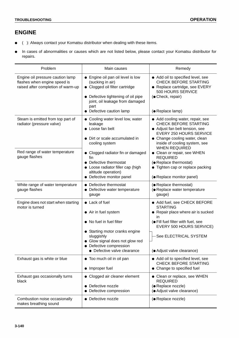
TROUBLESHOOTING OPERATION
3-140
ENGINE
● ( ): Always contact your Komatsu distributor when dealing with these items.
● In cases of abnormalities or causes which are not listed below, please contact your Komatsu distributor forrepairs.
Problem Main causes Remedy
Engine oil pressure caution lamp flashes when engine speed is raised after completion of warm-up
● Engine oil pan oil level is low (sucking in air)
● Clogged oil filter cartridge
● Defective tightening of oil pipe joint, oil leakage from damaged part
● Defective caution lamp
● Add oil to specified level, see CHECK BEFORE STARTING
● Replace cartridge, see EVERY 500 HOURS SERVICE
(● Check, repair)
(● Replace lamp)
Steam is emitted from top part of radiator (pressure valve)
● Cooling water level low, water leakage
● Loose fan belt
● Dirt or scale accumulated in cooling system
● Clogged radiator fin or damaged fin
● Defective thermostat ● Loose radiator filler cap (high
altitude operation)● Defective monitor panel
● Add cooling water, repair, see CHECK BEFORE STARTING
● Adjust fan belt tension, see EVERY 250 HOURS SERVICE
● Change cooling water, clean inside of cooling system, see WHEN REQUIRED
● Clean or repair, see WHEN REQUIRED
(● Replace thermostat)● Tighten cap or replace packing
(● Replace monitor panel)
Red range of water temperature gauge flashes
White range of water temperature gauge flashes
● Defective thermostat ● Defective water temperature
gauge
(● Replace thermostat)(● Replace water temperature
gauge)
Engine does not start when starting motor is turned
● Lack of fuel
● Air in fuel system
● No fuel in fuel filter
● Starting motor cranks engine sluggishly
● Glow signal does not glow red● Defective compression
● Defective valve clearance
● Add fuel, see CHECK BEFORE STARTING
● Repair place where air is sucked in
(● Fill fuel filter with fuel, see EVERY 500 HOURS SERVICE)
See ELECTRICAL SYSTEM
(● Adjust valve clearance)
Exhaust gas is white or blue ● Too much oil in oil pan
● Improper fuel
● Add oil to specified level, see CHECK BEFORE STARTING
● Change to specified fuel
Exhaust gas occasionally turns black
● Clogged air cleaner element
● Defective nozzle ● Defective compression
● Clean or replace, see WHEN REQUIRED
(● Replace nozzle)(● Adjust valve clearance)
Combustion noise occasionally makes breathing sound
● Defective nozzle (● Replace nozzle)
https://tractormanualz.com
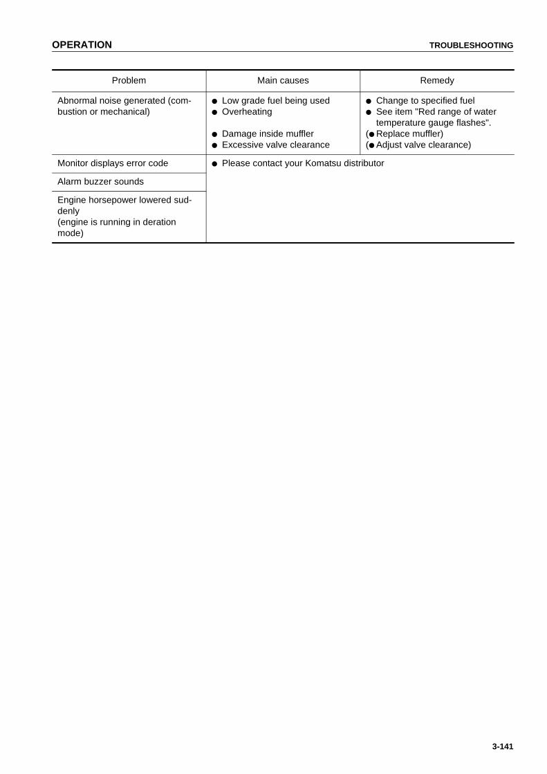
OPERATION TROUBLESHOOTING
3-141
Abnormal noise generated (com-bustion or mechanical)
● Low grade fuel being used ● Overheating
● Damage inside muffler ● Excessive valve clearance
● Change to specified fuel● See item "Red range of water
temperature gauge flashes".(● Replace muffler)(● Adjust valve clearance)
Monitor displays error code ● Please contact your Komatsu distributor
Alarm buzzer sounds
Engine horsepower lowered sud-denly(engine is running in deration mode)
Problem Main causes Remedy
https://tractormanualz.com

4-1
MAINTENANCE41
5
WARNINGPlease read and make sure that you understand the safetyvolume before reading this section.
https://tractormanualz.com
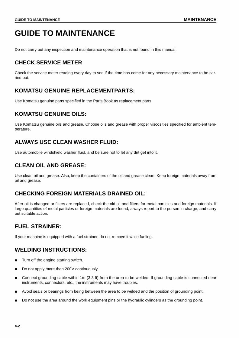
GUIDE TO MAINTENANCE MAINTENANCE
4-2
GUIDE TO MAINTENANCE
Do not carry out any inspection and maintenance operation that is not found in this manual.
CHECK SERVICE METER
Check the service meter reading every day to see if the time has come for any necessary maintenance to be car-ried out.
KOMATSU GENUINE REPLACEMENTPARTS:
Use Komatsu genuine parts specified in the Parts Book as replacement parts.
KOMATSU GENUINE OILS:
Use Komatsu genuine oils and grease. Choose oils and grease with proper viscosities specified for ambient tem-perature.
ALWAYS USE CLEAN WASHER FLUID:
Use automobile windshield washer fluid, and be sure not to let any dirt get into it.
CLEAN OIL AND GREASE:
Use clean oil and grease. Also, keep the containers of the oil and grease clean. Keep foreign materials away fromoil and grease.
CHECKING FOREIGN MATERIALS DRAINED OIL:
After oil is changed or filters are replaced, check the old oil and filters for metal particles and foreign materials. Iflarge quantities of metal particles or foreign materials are found, always report to the person in charge, and carryout suitable action.
FUEL STRAINER:
If your machine is equipped with a fuel strainer, do not remove it while fueling.
WELDING INSTRUCTIONS:
● Turn off the engine starting switch.
● Do not apply more than 200V continuously.
● Connect grounding cable within 1m (3.3 ft) from the area to be welded. If grounding cable is connected nearinstruments, connectors, etc., the instruments may have troubles.
● Avoid seals or bearings from being between the area to be welded and the position of grounding point.
● Do not use the area around the work equipment pins or the hydraulic cylinders as the grounding point.
https://tractormanualz.com

MAINTENANCE GUIDE TO MAINTENANCE
4-3
DO NOT DROP THINGS INSIDE MACHINE:
● When opening inspection windows or the oil filler port of the tank to carry out inspection, be careful not to dropnuts, bolts, or tools inside the machine.If such things are dropped inside the machine, it will cause damage and malfunction of the machine, and willlead to failure. If you drop anything inside the machine, always remove it immediately.
● Do not put unnecessary things in your pockets. Carry only things which are necessary for inspection.
DUSTY WORKSITES:
When working at dusty worksites, do as follows:
● Inspect the air cleaner clogging monitor frequently to see if the air cleaner is clogged.Clean the air cleaner element at a shorter interval than specified.
● Clean the radiator core frequently to avoid clogging.
● Clean and replace the fuel filter frequently.
● Clean electrical components, especially the starting motor and alternator, to avoid accumulation of dust.
● When inspecting or changing the oil, move the machine to a place that is free of dust to prevent dirt from get-ting into the oil.
AVOID MIXING OILS:
Never mix different kinds of oil. If a different type of oil has to be added, drain the old oil and replace all the oil withthe new type of oil.
PRECAUTIONS FOR OPENING AND CLOSING ENGINE SIDE COVER
Precautions when opening and closing engine side cover:● When standing on track to open the engine side cover,
adopt a standing position, hold the side cover with boththumbs, and open it slowly with your other fingers.
● When the engine side cover is open, do not open or closethe cab. Before opening or closing the cab, always close the engineside cover first.
https://tractormanualz.com
GUIDE TO MAINTENANCE MAINTENANCE
4-4
LOOKING THE INSPECTION COVERS:
When carrying out maintenance with the inspection cover open, lock it in position securely with a lock bar. Ifinspection or maintenance is carried out with the inspection cover open and not locked in position, there is a haz-ard that it may be suddenly blown shut by the wind and cause injury to the worker.
HYDRAULIC SYSTEM - AIR BLEEDING
After repairing or replacing the hydraulic equipment or after removing the hydraulic piping, it is necessary to bleedthe air from the circuit. For details, see "PROCEDURE FOR BLEEDING AIR IN HYDRAULIC SYSTEM (PAGE 4-42)".
PRECAUTIONS WHEN INSTALLING HYDRAULIC HOSES
● When removing parts at locations where there are O-rings or gasket seals, clean the mounting surface, andreplace with new parts.When doing this, be careful not to forget to assemble the O-rings and gaskets.
● When installing the hoses, do not twist them or bend them into loops with a small radius.
This will cause damage to the hose and markedly reduce its service life.
CHECK AFTER INSPECTION AND MAINTENANCE WORKS:
If you forget to carry out the checks after inspection and maintenance, unexpected problems may occur, and thismay lead to serious injuly or property damage. Always do as follows.
● Checks after operation (with engine stopped)
● Have any inspection and maintenance points been forgotten?
● Have all inspection and maintenance items been carried out correctly?
● Have any tools or parts been dropped inside the machine? It is particularly dangerous if parts are droppedinside machine and get caught in the lever linkage mechanism.
● Is there any leakage of water or oil? Have all the bolts been tightened?
● Checks when engine is running
● For the checks when the engine is running, see "TWO WORKERS FOR MAINTENANCE WHEN ENGINEIS RUNNING (PAGE 2-30)" in the SAFETY section, and take care of safety sufficiently.
● Check that the inspected and maintained parts work normally.
● Raise the engine speed and check for fuel leakage and oil leakage.
FUEL AND LUBRICANTS TO MATCH THE AMBIENT TEMPERATURE
Select the fuel and lubricants to match the ambient temperature.For details, see "USE OF FUEL, COOLANT AND LUBRICANTS ACCORDING TO AMBIENT TEMPERATURE(PAGE 4-11)".
https://tractormanualz.com
MAINTENANCE OUTLINE OF SERVICE
4-5
OUTLINE OF SERVICE
OUTLINE OF OIL, FUEL, COOLANT
OIL
● Oil is used in the engine and work equipment under extremely severe conditions (high temperature, high pres-sure), and is deteriorates with use.Always use oil that matches the grade and temperature for use given in the Operation and Maintenance Man-ual. Even if the oil is not dirty, always change the oil after the specified interval.
● Oil corresponds to blood in the human body, so always be careful when handling it to prevent any impurities(water, metal particles, dirt, etc.) from getting in.The majority of problems with machine are caused by the entry of such impurities.Take particular care not to let any impurities get in when storing or adding oil.
● Never mix oils of different grades or brands.
● Always add the specified amount of oil.Having too much oil or too little oil are both causes of problems.
● If the oil in the work equipment is not clear, there is probably water or air getting into the circuit. In such cases,please contact your Komatsu distributor.
● When changing the oil, always replace the related filters. In particular, when replacing the engine oil filter, fillthe new filter with fresh, clean specified oil before installing.
● We recommend you to have an analysis made of the oil periodically to check the condition of the machine. Forthose who wish to use this service, please contact your Komatsu distributor.
FUEL
● The fuel pump is a precision instrument, and if fuel containing water or dirt is used, it cannot work properly.
● Be extremely careful not to let impurities get in when storing or adding fuel.
● Always use the fuel specified in the Operation and Maintenance Manual.Fuel may congeal depending on the temperature when it is used (particularly in low temperature below -15ºC(5ºF)), so it is necessary to change to a fuel that matches the temperature.
● To prevent the moisture in the air from condensing and forming water inside the fuel tank, always fill the fueltank after completing the day's work.
● Before starting the engine, or when 10 minutes have passed after adding fuel, drain the sediment and waterfrom the fuel tank.
● If the engine runs out of fuel, or if the filters have been replaced, it is necessary to bleed the air from the circuit.
https://tractormanualz.com

OUTLINE OF SERVICE MAINTENANCE
4-6
COOLANT
● River water contains large amounts of calcium and other impurities, so if it is used, scale will stick to theengine and radiator, and this will cause defective heat exchange and overheating.Do not use water that is not suitable for drinking.
● When using anti-freeze, always observe the precautions given in the Operation and Maintenance Manual.
● Komatsu machines are supplied with Komatsu original anti-freeze in the coolant when the machine is shipped.This anti-freeze is effective in preventing corrosion of the cooling system.The anti-freeze can be used continuously for two years or 4000 hours. Therefore, it can be used as it is evenin hot areas.
● Anti-freeze is flammable, so be extremely careful not to expose it to flame or fire.
● The proper mixing proportion of the antifreeze depends on the ambient temperature. For the mixing propor-tion, see "CLEAN INSIDE OF COOLING SYSTEM (PAGE 4-22)".
● If the engine overheats, wait for the engine to cool before adding coolant.
● If the coolant level is low, it will cause overheating and will also cause problems with corrosion from the air inthe coolant.
GREASE
● Grease is used to prevent twisting and noise at the joints.
● The nipples not included in the MAINTENANCE section are nipples used when overhauling, so they do notneed grease.If any part becomes stiff or generates noise after being used for a long time, grease it.
● Always wipe off all of the old grease that is pushed out when greasing.Be particularly careful to wipe off the old grease in places where sand or dirt sticking in the grease wouldcause wear of the rotating parts.
https://tractormanualz.com

MAINTENANCE OUTLINE OF SERVICE
4-7
CARRYING OUT KOWA (Komatsu Oil Wear Analysis)
KOWA is a maintenance service that makes it possible to prevent machine failures and down-time. With KOWA,the oil is periodically sampled and analyzed. This enables early detection of wear of the machine drive parts andother abnormalities.
Periodic use of KOWA makes the following possible:
● It enables abnormalities to be detected early, leading to reduction of repair costs and machine downtime.
● It enables repair schedules to be planned, leading to improved machine availability.
KOWA ANALYSIS ITEMS
● Analysis of metal wear particlesThis uses an ICP (Inductively Coupled Plasma) analyzer tomeasure the density of metal wear particles in the oil.
● Measurement of particle quantityThis uses a PQI (Particle Quantifier Index) measurer tomeasure the quantity of large iron particles in the oil.
● OthersMeasurements are made of items such as the ratio of water or fuel in the oil, and the dynamic viscosity.
OIL SAMPLING
● Sampling interval250 hours: Engine500 hours: Other components
● Precautions when sampling● Make sure that the oil is well mixed before sampling.● Carry out sampling regularly at fixed intervals.● Do not carry out sampling on rainy or windy days when water or dust can get into the oil.
For further details of KOWA, please contact your Komatsu distributor.
https://tractormanualz.com

OUTLINE OF SERVICE MAINTENANCE
4-8
STORING OIL AND FUEL
● Keep indoors to prevent any water, dirt, or other impurities from getting in.
● When keeping drum cans for a long period, put the drum on its side so that the filler port of the drum can is atthe side. (To prevent moisture from being sucked in)If drum cans have to be stored outside, cover them with a waterproof sheet or take other measures to protectthem.
● To prevent any change in quality during long-term storage, be sure to use in the order of first in - first out (usethe oldest oil or fuel first).
FILTERS
● Filters are extremely important safety parts. They prevent impurities in the fuel and air circuits from enteringimportant equipment and causing problems.
Replace all filters periodically. For details, see the Operation and Maintenance Manual.
However, when working in severe conditions, replace the filters at shorter intervals according to the oil and fuel(sulfur content) being used.
● Never try to clean the filters (cartridge type) and use them again. Always replace with new filters.
● When replacing oil filters, check if any metal particles are affixed to the old filter. If any metal particles arefound, please contact your Komatsu distributor.
● Do not open packs of spare filters until just before they are to be used.
● Always use Komatsu genuine filters.
ELECTRIC SYSTEM MAINTENANCE
● It is extremely dangerous if the electrical equipment becomes wet or the covering of the wiring is damaged.This will cause electrical leakage and may lead to malfunction of the machine. Do not wash the inside of theoperator's cab with water. When washing the machine, be careful not to let water get into the electrical compo-nents.
● Service relating to the electric system is check of fan belt tension, check of damage or wear in the fan belt andcheck of battery fluid level.
● Never install any electric components other than there specified by Komatsu.
● External electrical interference may cause malfunction of the control system controller, so before installing aradio receiver or other wireless equipment, please contact your Komatsu distributor.
● When working at the seashore, carefully clean the electric system to prevent corrosion.
● When installing an operator's cab cooler or any other electrical equipment, connect it to an independent powersource connector. The optional power source must never be connected to the fuse, starting switch, or batteryrelay.
https://tractormanualz.com

MAINTENANCE WEAR PARTS
4-9
WEAR PARTSWear parts such as the filter element, air cleaner element etc. are to be replaced at the time of periodic mainte-nance or before their abrasion limits.
The wear parts should be changed correctly in order to use the machine economically.
When changing parts,use Komatsu genuine parts of excellent quality.
When ordering parts, please check the part number in the parts book.
WEAR PARTS LISTThe parts in parentheses are to be replaced at the same time.
Item Part No. Part NameWeight
(kg)Q'ty
Replacement frequency
Engine oil filter 600-211-1340 Cartridge — 1
Every 500 hour service
Power train filter07063-01100
(07000-02130)Element(O-ring)
——
1(1)
Fuel filter 600-311-3110 Cartridge — 1
Hydraulic tank breather 20Y-60-21470 Cap element — 1
Corrosion resistor 600-411-1161 Cartridge — 1Every 1000 hours seviceCharge filter
07063-51054(07000-02110)
Element(O-ring)
——
1(1)
Hydraulic oil filter07063-51100
(07000-02130)Element(O-ring)
——
1(1)
Every 2000 hours service
Air cleaner6128-81-7042 Element ass'y — 1
—600-181-4401 Outer element ass'y — 1
Air conditioner
Fresh filter 14X-911-7750 Filter — 2
Recirc filter 14X-911-7741 Filter — 1
Blade
Semi U-blade
195-70-1249217A-71-1135117M-71-2193017M-71-2194017A-71-1245117M-71-21530
Cutting edgeCutting edgeEnd bit (left)End bit (right)(Bolt)(Nut)
103.4576363——
1211
(33)(33)
—U-blade
17A-72-1222117M-72-2116017M-71-2193017M-71-2194017A-71-1245117M-71-21530
Cutting edgeCutting edgeEnd bit (left)End bit (right)(Bolt)(Nut)
69586363——
2211
(36)(36)
Angledozer
175-70-26310175-70-21115175-71-11454175-71-11530175-70-21126175-70-21136175-71-11463175-71-11530
Cutting edgeCutting edge(Bolt)(Nut)End bit (left)End bit (right)(Bolt)(Nut)
48.864.1——3737——
12
(25)(25)
11
(14)(14)
https://tractormanualz.com

WEAR PARTS MAINTENANCE
4-10
NOTICEWhen handling parts that weigh more than 25 kg (55 lb), remember that they are heavy objects, and takethe necessary care.
Ripper
Multi175-78-31230195-78-2132009244-02508
PointProtector(Pin)
1513—
33
(9)—
Giant175-78-31230195-78-2132009244-02508
PointProtector(Pin)
1513—
113
—
Item Part No. Part NameWeight
(kg)Q'ty
Replacement frequency
https://tractormanualz.com

MAINTENANCE USE OF FUEL, COOLANT AND LUBRICANTS ACCORDING TO AMBIENT TEMPERATURE
4-11
USE OF FUEL, COOLANT AND LUBRICANTS ACCORDING TO AMBIENT TEMPERATURE
PROPER SELECTION OF FUEL, COOLANT AND LUBRICANTS
NOTICEUse only diesel fuel.The engine mounted on this machine employs electronic control and a high-pressure fuel injection deviceto obtain good fuel consumption and good exhaust gas characteristics. For this reason, it requires highprecision for the parts and good lubrication.If kerosene or other fuel with low lubricating ability is used, there will be a big drop in durability.
https://tractormanualz.com

USE OF FUEL, COOLANT AND LUBRICANTS ACCORDING TO AMBIENT TEMPERATURE MAINTENANCE
4-12
REMARK● When fuel sulphur content is less than 0.5%, change oil in the oil pan every periodic maintenance hours
described in this manual.Change oil according to the following table if fuel suiphur content is above 0.5%.
● When starting the engine in an atmosphric temterature of lower than 0ºC (32ºF), be sure to use engine oil ofSAE10W, SAE10W-30 and SAE15W-40, even though an atmospheric temparature gose up to 10ºC (50ºF)more or less in the day time.Use CE or CF class oil for the engine oil.
● Use API classification CD as engine oil and if API classification CC, reduce the engine oil change interval tohalf.
● There is no problem if single grade oil is mixed with multigrade oil (SAE10W-30, 15W-40), but be sure to addsingle grade oil than matches the temparature in the table.
● We recommend Komatsu genuine oil which has been specifically formulated and approved for use in engineand hydrauric work equipment applications.
Specified capacity: Total amount of oil including oil for components and oil in piping.
Refill capacity: Amount of oil needed to refill system during normal inspection and maintenance.
ASTM: American Society of Testing and Material
SAE: Society of Automotive Engineers
API: American Petroleum Insitute
Fuel sulphur contentCharge interval of oil in
engine oil pan
0.5 to 1.0% 1/2 of regular interval
Above 1.0% 1/4 of regular interval
https://tractormanualz.com

MAINTENANCE USE OF FUEL, COOLANT AND LUBRICANTS ACCORDING TO AMBIENT TEMPERATURE
4-13
No. Supplier
Engine Oil[CD or CE]
SAE10W, 30, 40 10W30, 15W40(The 15W40 oilmarked * is CE.)
Gear Oil[GL-4 or GL-5]
SAE80, 90, 140
Grease[Lithium-Base]
NLGI No.2
Anti-freeze Coolant
[Ethylene GlycolBase]
Permanent Type
1 KOMATSU
EO10-CDEO30-CDEO10-30CDEO15-40CD
GO90GO140
G2-LIG2-LI-S
AF-ACLAF-PTLAF-PT(Winter, one season type)
2 AGIP
Diesel sigma S super dieselmulti- grade*Sigma turbo
Rotra MP GR MU/EP -
3 AMOCO *Amoco 300Multi-purpose gear oil
PYKON premium grease
-
4 ARCO *Arcofleet S3 pius Arco HD gear oilLitholine HEP 2 Arco EP moly D
-
5 BP Vanellus C3Gear oil EPHypogear EP
Energrease LS-EP2 Antifreeze
6 CALTEX*RPM delo 400RPM delo 450
Universal thubanUniversal thuban EP
Marfak all purpose 2Ultra-duty grease 2
AF engine coolant
7 CASTROL*Turbomax *RX superCRD
EPEPXHypoyHypoy BHypoy C
MS3Spheerol EPL2
Anti-freeze
8 CHEVRON *Delo 400 Universal gear Ultra-duty grease 2 -
9 CONOCO *Fleet motor oilUniversal gear lubricant
Super-sta grease -
10 ELFMultiperformance 3CPerformance 3C
-Tranself EPTranself EP type 2
Glacelf
11EXXON (ESSO)
Essolube D3*Essolube XD-3*Essolube XD-3 Extra*Esso heavy dutyExxon heavy duty
Gear oil GPGear oil GX
Beacon EP2 All season coolant
12 GULFSuper duty motor oil*Super duty plus
Multi-purpose gear lubricant
Gulfcrown EP2Gulfcrown EP special
Antifeeze and coolant
13 MOBILDelvac 1300*Delvac super10W-30, 15W-40
Mobilube GXMobilube HD
Mobilux EP2Mobilgrease 77Mobilgrease special
-
14 PENNZOIL*Superme duty fleet motor oil
Multi-purpose 4092Multi-purpose 4140
Multi-purpose white grease 705707L White-bearing grease
Anti-freeze and summer coolant
https://tractormanualz.com

USE OF FUEL, COOLANT AND LUBRICANTS ACCORDING TO AMBIENT TEMPERATURE MAINTENANCE
4-14
15 PETROFINA FINA kappa TDFINA potonic NFINA potonic NE
FINA marson EPL2 FINA tamidor
16 SHELL Rimura XSpirax EPSpirax heavy duty
Albania EP grease -
17 SUN -Sunoco GL5 gear oil
Sunoco ultra pres-tige 2EPSun prestige 742
Sunoco antifreeze and summer cool-ant
18 TEXACO*Ursa super plus Ursa premium
MultigearMultifak EP2 Starplex 2
Coda 2055 startex antifreeze coolant
19 TOTALRubia S *Rubia X
Total EPTotal Transmission TM
Multis EP2 Antigal/antifreeze
20 UNION *Guardol MP gear lube LS Unoba EP -
21 VEEDOL*Turbostar*Diesel star MDC
Multigear Multigear BMultigear C
- Antifreeze
No. Supplier
Engine Oil[CD or CE]
SAE10W, 30, 40 10W30, 15W40(The 15W40 oilmarked * is CE.)
Gear Oil[GL-4 or GL-5]SAE80, 90, 140
Grease[Lithium-Base]
NLGI No.2
Anti-freeze Coolant
[Ethylene GlycolBase]
Permanent Type
https://tractormanualz.com

MAINTENANCE STANDARD TIGHTENING TORQUES FOR BOLTS AND NUTS
4-15
STANDARD TIGHTENING TORQUES FOR BOLTS AND NUTS
TORQUE LIST
CAUTIONIf nuts, bolts, or other parts are not tightened to the specified torque, it will cause looseness or damage tothe tightened parts, and this will cause failure of the machine or problems with operation.Always pay careful attention when tightening parts.
Unless otherwise specified, tighten the metric nuts and bolts to the torque shown in the table below.
The tightening torque is determined by the width across the flats of the nut and bolt.
If it is necessary to replace any nut or bolt, always use a Komatsu genuine part of the same size as the part thatwas replaced.
Apply the following table for Hydraulic Hose.
Thread diameter a(mm)
Width across
flat b(mm)
Tightening torque
Target value Service limit
N•m kgf•m lbft N•m kgf•m lbft
6 10 13.2 1.35 9.8 11.8 - 14.7 1.2 - 1.5 8.7 - 10.8
8 13 31 3.2 23.1 27 - 34 2.8 - 3.5 20.3 - 25.3
10 17 66 6.7 48.5 59 - 74 6.0 - 7.5 43.4 - 54.2
12 19 113 11.5 83.2 98 - 123 10.0 - 12.5 72.3 - 90.4
14 22 177 18 130.2 157 - 196 16.0 - 20.0 115.7 - 144.7
16 24 279 28.5 206.1 245 - 309 25.0 - 31.5 180.8 - 227.8
18 27 382 39 282.1 343 - 425 35.0 - 43.5 253.2 - 314.6
20 30 549 56 405.0 490 - 608 50.0 - 62.0 361.7 - 448.4
22 32 745 76 549.7 662 - 829 67.5 - 84.5 488.2 - 611.2
24 36 927 94.5 683.5 824 - 1030 84.0 - 105.0 607.6 - 759.5
27 41 1320 135.0 976.5 1180 - 1470 120.0 - 150.0 868.0 - 1085.0
30 46 1720 175.0 1265.8 1520 - 1910 155.0 - 195.0 1121.1 - 1410.4
33 50 2210 225.0 1627.4 1960 - 2450 200.0 - 250.0 1446.6 - 1808.3
36 55 2750 280.0 2025.2 2450 - 3040 250.0 - 310.0 1808.3 - 2242.2
39 60 3280 335.0 2423.1 2890 - 3630 295.0 - 370.0 2133.7 - 2676.2
Thread diameter a(mm)
Width across
flat b(mm)
Tightening torque
Target value Service limit
N•m kgf•m lbft N•m kgf•m lbft
10 14 14.7 1.5 10.8 12.7 - 16.7 1.3 - 1.7 9.4 - 12.3
14 19 29.4 3.0 21.7 27.5 - 39.2 2.8 - 4.0 20.3 - 28.9
18 24 78.5 8.0 57.3 58.8 - 98.1 6.0 - 10.0 43.4 - 72.3
22 27 117.7 12.0 86.8 88.3 - 137.3 9.0 - 14.0 65.1 - 101.3
24 32 147.1 15.0 108.5 117.7 - 176.5 12.0 - 18.0 86.8 - 130.2
30 36 215.7 22.0 159.1 176.5 - 245.2 18.0 - 25.0 130.2 - 180.8
33 41 255.0 26.0 188.1 215.7 - 284.4 22.0 - 29.0 159.1 - 209.8
https://tractormanualz.com

PERIODIC REPLACEMENT OF SAFETY CRITICAL PARTS MAINTENANCE
4-16
PERIODIC REPLACEMENT OF SAFETY CRITICAL PARTS
To ensure safety at all times when operating or driving the machine, the user of the machine must always carry outperiodic maintenance. In addition, to further improve safety, the parts in the safety-critical parts list on the nextpage must also be replaced at the specified interval. These parts are particularly closely connected to safety andfire prevention, so please contact your Komatsu distributor to have them replaced.
With these parts, the material changes as time passes, or they easily wear out or deteriorate. However, it is difficultto judge the condition of the parts simply by periodic maintenance, so they should always be replaced after a fixedtime has passed, regardless of their condition. This is necessary to ensure that they always maintain their functioncompletely.
However, if these parts show any abnormality before the replacement interval has passed, they should be repairedor replaced immediately.
If the hose clamps show any deterioration, such as deformation or cracking, replace the clamps at the same as thehoses.
In addition, carry out the following checks for the hydraulic hoses not listed as periodic replacement parts. If anyabnormality is found, tighten or replace the parts.
When replacing the hoses, always replace the O-rings, gaskets, and other such parts at the same time.
Ask your Komatsu distributor to replace the critical parts.
https://tractormanualz.com

MAINTENANCE PERIODIC REPLACEMENT OF SAFETY CRITICAL PARTS
4-17
SAFETY CRITICAL PARTS
No. Safety critical parts for periodic replacement Q'ty Replacement interval
1 Fuel tank - hand priming pump 1
Every 2 years or 4000 hours, whichever comes sooner
2 Engine overflow nipple - joint (bottom of fuel tank) 1
3 Engine overflow nipple - joint (bottom of fuel tank) 1
4 Joint (bottom of fuel tank) - fuel tank (overflow) 1
5 Joint (bottom of fuel tank) - fuel tank (spill) 1
6 Hand priming pump - supply pump 1
7 P/L pump - P/L filter 1
8 Steering case cover - HSS motor gear train 1
9 P/L filter - transmission control valve 1
10 Transmission control valve - brake valve 1
11 Torque converter - oil cooler 1
12 Oil cooler - transmission case, torque converter case 1
13Central pressure detection hose - transmission case, torque converter case
1
14 Hydraulic tank - charge pump 1
15 Charge pump - charge filter 1
16 HSS, PPC charge valve - accumulator 1
17 HSS, PPC charge valve - hydraulic tank 1
18 HSS, PPC charge valve - PPC lock valve 1
19 PPC lock valve - PPC valve (blade) 1
20 PPC lock valve - PPC valve (ripper) 1
21 HSS, PPC charge valve - CLSS valve 1
22 HSS, PPC charge valve - HSS pump 1
23 PPC relief valve - HSS pump 1
24 HSS pump - HSS motor 1
25 HSS pump - HSS motor 1
26 HSS motor - central drain block 1
27 Central drain block - hydraulic tank 1
28 HSS motor - central drain block 1
29 HSS motor - central drain block 1
30 HSS pump - central drain block 1
31 Central drain block - cooler bypass valve 1
https://tractormanualz.com
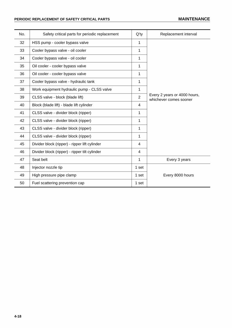
PERIODIC REPLACEMENT OF SAFETY CRITICAL PARTS MAINTENANCE
4-18
32 HSS pump - cooler bypass valve 1
Every 2 years or 4000 hours, whichever comes sooner
33 Cooler bypass valve - oil cooler 1
34 Cooler bypass valve - oil cooler 1
35 Oil cooler - cooler bypass valve 1
36 Oil cooler - cooler bypass valve 1
37 Cooler bypass valve - hydraulic tank 1
38 Work equipment hydraulic pump - CLSS valve 1
39 CLSS valve - block (blade lift) 2
40 Block (blade lift) - blade lift cylinder 4
41 CLSS valve - divider block (ripper) 1
42 CLSS valve - divider block (ripper) 1
43 CLSS valve - divider block (ripper) 1
44 CLSS valve - divider block (ripper) 1
45 Divider block (ripper) - ripper lift cylinder 4
46 Divider block (ripper) - ripper tilt cylinder 4
47 Seat belt 1 Every 3 years
48 Injector nozzle tip 1 set
Every 8000 hours49 High pressure pipe clamp 1 set
50 Fuel scattering prevention cap 1 set
No. Safety critical parts for periodic replacement Q'ty Replacement interval
https://tractormanualz.com

MAINTENANCE MAINTENANCE SCHEDURE CHART
4-19
MAINTENANCE SCHEDURE CHART
MAINTENANCE SCHEDURE CHART
INITIAL 250 HOURS MAINTENANCEREPLACE POWER TRAIN OIL FILTER ELEMENT........................................................................................... 4-52
CHANGE OIL IN POWER TRAIN CASE, WASH STRAINERS.......................................................................... 4-57
CHANGE OIL IN FINAL DRIVE CASE ............................................................................................................... 4-59
REPLACE CHARGE FILTER ELEMENT............................................................................................................ 4-63
CHANGE OIL IN HYDRAULIC TANK,REPLACE HYDRAULIC OIL FILTER ELEMENT ................................... 4-65
WHEN REQUIREDCLEAN INSIDE OF COOLING SYSTEM............................................................................................................ 4-22
CHECK, CLEAN AND REPLACE AIR CLEANER ELEMENT ............................................................................ 4-25
CHECK ELECTRICAL INTAKE AIR HEATER.................................................................................................... 4-27
CHECK TRACK TENSION ................................................................................................................................. 4-27
CHECK AND TIGHTEN TRACK SHOE BOLTS................................................................................................. 4-29
REVERSE AND REPLACE THE END BITS AND CUTTING EDGES................................................................ 4-30
CLEAN, CHECK RADIATOR FINS..................................................................................................................... 4-31
REPLACE AIR CONDITIONER BELT ................................................................................................................ 4-32
CLEAN, CHECK HYDRAULIC COOLER FINS .................................................................................................. 4-33
CLEAN, CHECK AIR CONDITIONER CONDENSER FINS ............................................................................... 4-34
ADJUST IDLER CLEARANCE............................................................................................................................ 4-34
CHECK UNDERCARRIAGE OIL ........................................................................................................................ 4-35
CLEAN AIR CONDITIONER AIR FILTER........................................................................................................... 4-36
CHECK, ADJUST AIR CONDITIONER .............................................................................................................. 4-37
GREASE DOOR HINGE..................................................................................................................................... 4-38
CHECK DOOR LOCK STRIKER ........................................................................................................................ 4-38
CHECK DOOR LATCH....................................................................................................................................... 4-39
REPLACE DOOR DAMPER ............................................................................................................................... 4-40
CHECK WINDOW WASHER FLUID LEVEL, ADD FLUID ................................................................................. 4-40
REPLACE WIPER BLADE.................................................................................................................................. 4-41
PROCEDURE FOR BLEEDING AIR IN HYDRAULIC SYSTEM ........................................................................ 4-42
PROCEDURE FOR RELEASING INTERNAL PRESSURE OF HYDRAULIC SYSTEM.................................... 4-42
CHECK BEFORE STARTING
EVERY 250 HOURS SERVICELUBRICATING.................................................................................................................................................... 4-44
CHECK OIL LEVEL IN FINAL DRIVE CASE, ADD OIL...................................................................................... 4-47
CHECK LEVEL OF BATTERY ELECTROLYTE................................................................................................. 4-47
CHECK, ADJUST ALTERNATOR DRIVE BELT TENSION ............................................................................... 4-49
CHECK BRAKE PERFORMANCE ..................................................................................................................... 4-50
https://tractormanualz.com

MAINTENANCE SCHEDURE CHART MAINTENANCE
4-20
EVERY 500 HOURS SERVICEREPLACE FUEL FILTER CARTRIDGE.............................................................................................................. 4-51
REPLACE POWER TRAIN OIL FILTER ELEMENT........................................................................................... 4-52
REPLACE HYDRAULIC TANK BREATHER ELEMENT .................................................................................... 4-53
CHECK AND REPLACE FAN BELT ................................................................................................................... 4-54
CHANGE OIL IN ENGINE OIL PAN, REPLACE ENGINE OIL FILTER CARTRIDGE........................................ 4-55
EVERY 1000 HOURS SERVICECHANGE OIL IN POWER TRAIN CASE, WASH STRAINERS.......................................................................... 4-57
CHANGE OIL IN FINAL DRIVE CASE ............................................................................................................... 4-59
CLEAN POWER TRAIN CASE BREATHER ...................................................................................................... 4-60
GREASE UNIVERSAL JOINT (2 PLACES)........................................................................................................ 4-60
REPLACE CORROSION RESISTOR CARTRIDGE...........................................................................................4-61
CHECK ALL TIGHTENING PARTS OF TURBOCHARGER .............................................................................. 4-61
GREASE TENSION PULLEY ASSEMBLY ......................................................................................................... 4-61
CHECK, CLEAN FUEL STRAINER .................................................................................................................... 4-62
REPLACE CHARGE FILTER ELEMENT............................................................................................................ 4-63
GREASE DLER ADJUSTMENT ROD ................................................................................................................ 4-64
CHECK FOR LOOSE ROPS MOUNT BOLTS ................................................................................................... 4-64
EVERY 2000 HOURS SERVICECHANGE OIL IN HYDRAULIC TANK,REPLACE HYDRAULIC OIL FILTER ELEMENT ................................... 4-65
CHECK PLAY OF TURBOCHARGER ROTOR.................................................................................................. 4-66
CLEAN, CHECK TURBOCHARGER .................................................................................................................. 4-66
CLEAN ENGINE BREATHER ELEMENT........................................................................................................... 4-66
CHECK ALTERNATOR, STARTING MOTOR.................................................................................................... 4-66
CHECK ENGINE VALVE CLEARANCE, ADJUST ............................................................................................. 4-66
CHANGE OIL IN DAMPER CASE, CLEAN DAMPER BREATHER ................................................................... 4-67
CHECK PIVOT BEARING OIL LEVEL, ADD OIL ............................................................................................... 4-68
CHECK INJECTOR............................................................................................................................................. 4-68
EVERY 4000 HOURS SERVICECHECK WATER PUMP ...................................................................................................................................... 4-69
CHECK FAN PULLEY AND TENSION PULLEY ................................................................................................ 4-69
CHECK VIBRATION DAMPER........................................................................................................................... 4-69
CHECKING FOR LOOSENESS OF HIGH-PRESSURE CLAMP, HARDENING OF RUBBER.......................... 4-70
CHECKING FOR MISSING FUEL SPRAY PREVENTION CAP, HARDENING OF RUBBER........................... 4-71
REPLACE INJECTOR NOZZLE TIP................................................................................................................... 4-71
EVERY 8000 HOURS SERVICEREPLACE HIGH-PRESSURE PIPING CLAMP.................................................................................................. 4-72
REPLACE FUEL SPLAY PREVENTION CAP.................................................................................................... 4-72
https://tractormanualz.com

MAINTENANCE SERVICE PROCEDURE
4-21
SERVICE PROCEDURE
INITIAL 250 HOURS MAINTENANCE(ONLY AFTER THE FIRST 250 HOURS)
Carry out the following maintenance only after the first 250 hours of operation on new machines.
● REPLACE POWER TRAIN OIL FILTER ELEMENT
● CHANGE OIL IN POWER TRAIN CASE, WASH STRAINERS (POWER TRAIN PUMP STRAINER, SCAV-ENGING PUMP STRAINER)
● CHANGE OIL IN FINAL DRIVE CASE
● REPLACE CHARGE FILTER ELEMENT
● CHANGE OIL IN HYDRAULIC TANK, REPLACE HYDRAULIC OIL FILTER ELEMENT
For details of the method of replacing or maintaining, see the section on EVERY 500 HOURS, 1000 HOURS AND2000 HOURS SERVICE.
https://tractormanualz.com

SERVICE PROCEDURE MAINTENANCE
4-22
WHEN REQUIRED
CLEAN INSIDE OF COOLING SYSTEM
WARNING● Soon after the engine has been stopped, the coolant is hot and can cause personal injury. Allow the
engine to cool before draining water.
● Never be under the machine with the engine running. To avoid serious injury, always stop the enginebefore being under the machine to open the drain valve.
● Never remove the radiator cap when the engine is at operating temperature. At operating temperature,the coolant is under pressure. Steam blowing up from the radiator could cause personal injury. Allowthe engine to cool until the radiator filler cap is cool enough to touch with your hand.Remove the filler cap slowly to relieve pressure.
Clean the inside of the cooling system, change the coolant and replace the corrosion resistor according to thetable below.
Stop the machine on level ground when cleaning or changing the coolant.
Use a permanent type of antifreeze.
If, for some reason, it is impossible to use permanent type antifreeze, use an antifreeze containing ethylene glycol.
Super Coolant (AF-ACL) has an anti-corrosion effect as well as an antifreeze effect.
The ratio of antifreeze to water depends on the ambient temperature, but to obtain the corrosion resistance effect,a minimum ratio of 30% by volume is necessary.
When deciding the ratio of antifreeze to water, check the lowest temperature in the past, and decide from the mix-ing rate table given below.
It is actually better to estimate a temperature about 10ºC (50ºF) lower when deciding the mixing rate.
Kind of coolantCleaning inside of cooling system
and changing coolantAdding corrosion resistor
Permanent type antifreeze (All season type)
Every year (autumn) or every 2000 hours whichever comes first
Every 500 hours and when cleaning the inside of the cooling system and when changing coolant.
Non permanent type antifreeze containing ethylene glycol (Winter, one season type)
Every 6 months (spring, autumn) (Drain antifreeze in spring, add antifreeze in autumn)
When not using antifreeze Every 6 months or every 1000 hours whichever comes first
https://tractormanualz.com
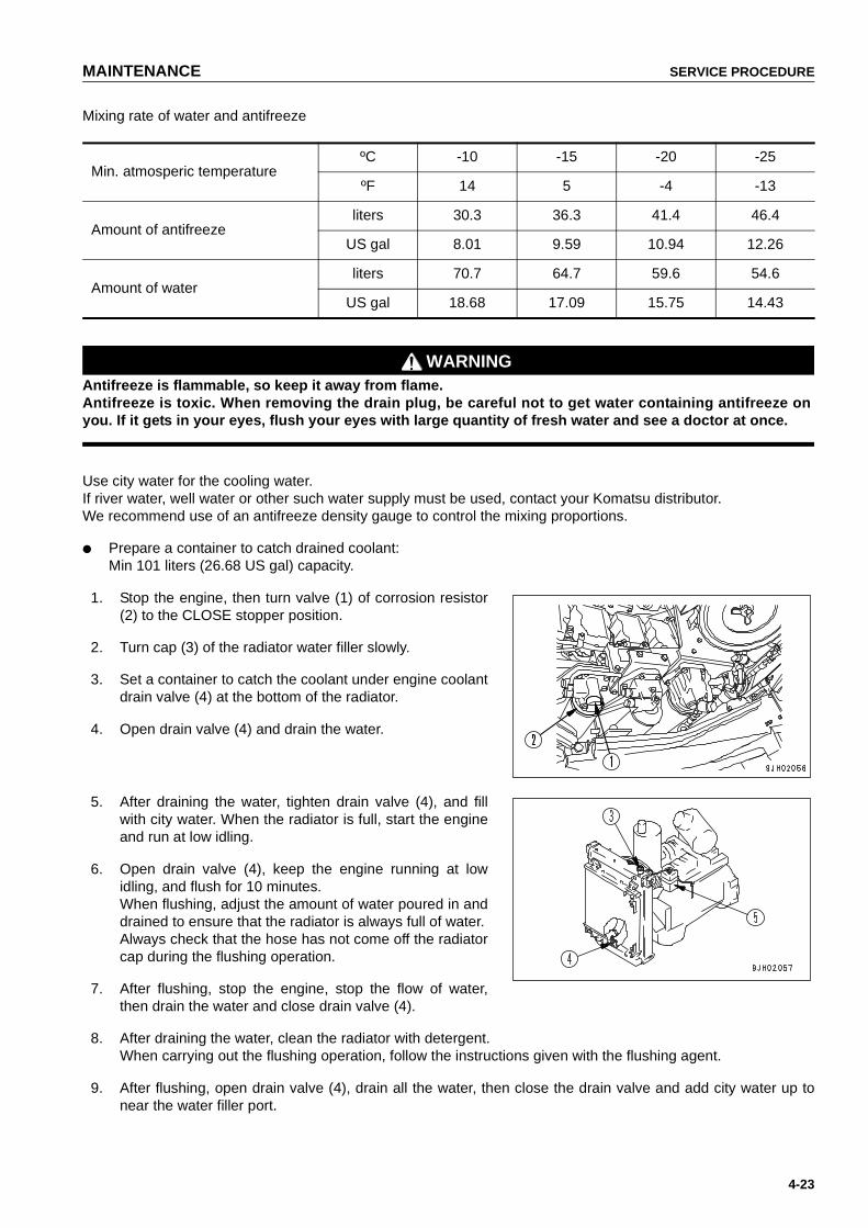
MAINTENANCE SERVICE PROCEDURE
4-23
Mixing rate of water and antifreeze
WARNINGAntifreeze is flammable, so keep it away from flame.Antifreeze is toxic. When removing the drain plug, be careful not to get water containing antifreeze onyou. If it gets in your eyes, flush your eyes with large quantity of fresh water and see a doctor at once.
Use city water for the cooling water.If river water, well water or other such water supply must be used, contact your Komatsu distributor.We recommend use of an antifreeze density gauge to control the mixing proportions.
● Prepare a container to catch drained coolant:Min 101 liters (26.68 US gal) capacity.
1. Stop the engine, then turn valve (1) of corrosion resistor(2) to the CLOSE stopper position.
2. Turn cap (3) of the radiator water filler slowly.
3. Set a container to catch the coolant under engine coolantdrain valve (4) at the bottom of the radiator.
4. Open drain valve (4) and drain the water.
5. After draining the water, tighten drain valve (4), and fillwith city water. When the radiator is full, start the engineand run at low idling.
6. Open drain valve (4), keep the engine running at lowidling, and flush for 10 minutes.When flushing, adjust the amount of water poured in anddrained to ensure that the radiator is always full of water.Always check that the hose has not come off the radiatorcap during the flushing operation.
7. After flushing, stop the engine, stop the flow of water,then drain the water and close drain valve (4).
8. After draining the water, clean the radiator with detergent.When carrying out the flushing operation, follow the instructions given with the flushing agent.
9. After flushing, open drain valve (4), drain all the water, then close the drain valve and add city water up tonear the water filler port.
Min. atmosperic temperatureºC -10 -15 -20 -25
ºF 14 5 -4 -13
Amount of antifreezeliters 30.3 36.3 41.4 46.4
US gal 8.01 9.59 10.94 12.26
Amount of waterliters 70.7 64.7 59.6 54.6
US gal 18.68 17.09 15.75 14.43
https://tractormanualz.com

SERVICE PROCEDURE MAINTENANCE
4-24
10. When the water reaches near the water filler port, open drain valve (4), run the engine at low idling, and carryout the flushing operation until clean water comes out.When flushing, adjust the amount of water added and drained to ensure that the radiator is always full ofwater.
11. When clean water comes out, stop the engine and close drain valve (4).
12. Replace the corrosion resistor, and turn valve (1) to the OPEN stopper position.For details of the method for replacing the corrosion resistor cartridge, see "REPLACE CORROSIONRESISTOR CARTRIDGE (PAGE 4-61)".
13. Fill with antifreeze and city water until the water overflows from the water filler. Determine the proportions ofantifreeze and water in accordance with the water and antifreeze mixture table.
14. Run the engine idle at a low speed for 5 minutes, then at a high speed for 5 minutes to bleed air mixed in thecooling water. (At this time, keep the water filler cap removed.)
15. Drain the cooling water inside sub-tank (5), clean theinside of the sub-tank,then fill again with cooling water toa point midway between the FULL and LOW marks.
16. Stop the engine,wait for 3 minutes,add city water until thewater level reaches near the water filler port,then tightenthe cap (3).
https://tractormanualz.com
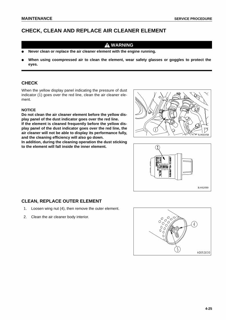
MAINTENANCE SERVICE PROCEDURE
4-25
CHECK, CLEAN AND REPLACE AIR CLEANER ELEMENT
WARNING● Never clean or replace the air cleaner element with the engine running.
● When using coompressed air to clean the element, wear safety glasses or goggles to protect theeyes.
CHECK
When the yellow display panel indicating the pressure of dustindicator (1) goes over the red line, clean the air cleaner ele-ment.
NOTICEDo not clean the air cleaner element before the yellow dis-play panel of the dust indicator goes over the red line. If the element is cleaned frequently before the yellow dis-play panel of the dust indicator goes over the red line, theair cleaner will not be able to display its performance fully,and the cleaning efficiency will also go down. In addition, during the cleaning operation the dust stickingto the element will fall inside the inner element.
CLEAN, REPLACE OUTER ELEMENT
1. Loosen wing nut (4), then remove the outer element.
2. Clean the air cleaner body interior.
https://tractormanualz.com

SERVICE PROCEDURE MAINTENANCE
4-26
3. Direct dry compressed air (less then 700 kPa (7 kg/cm2,100 psi)) to the element from inside along its folds,thendirect it from outside along its folds and again from inside.
1) Remove one seal from the outer element. The num-ber of times the outer element has been cleaned canbe seen by the number of removed seals.
2) Replace the outer element which has been cleaned6 times repeatedly or used throughout a year.Replace the inner element at the same time.
3) Replace the element when the air cleaner cloggedwarning lamp lights up soon after installing thecleaned element even though it has not beencleaned 6 times.
4) Check inner element mounting nuts for loosenessand, if necessary, retighten.
5) Replace seal washer (5) or wing nut (4) with newparts if they are broken.
NOTICEIf small holes or thinner parts are found on the elementwhen it is checked with an electric bulb after cleaning anddrying,replace the element.Do not use an element whose folds or gasket or seal aredamaged.When cleaning the element,do not hit it or beat it againstsomething.
4. Set the cleaned element.
REPLACING INNER ELEMENT
1. First remove the outer element, and then remove the inner element.
2. To prevent dust from getting in,use a clean cloth or tape to cover the air connector (outlet side).
3. Clean the air cleaner body interior,then remove the cover installed in Step 2.
4. Fit a new inner element to the connector and tighten it with nuts.Do not clean and reinstall a inner element.
5. Install the outer element.
6. After replacing the element, press dust indicator resetbutton (3) to return the yellow display panel to its originalposition.
https://tractormanualz.com

MAINTENANCE SERVICE PROCEDURE
4-27
CHECK ELECTRICAL INTAKE AIR HEATER
Before the start of the cold season (once a year), contact your Komatsu distributor to have the electrical intake airheater repaired or checked for dirt or disconnections.
CHECK TRACK TENSION
The wear of pins and bushings on the undercarriage will vary with the working conditions and soil properties. It isthus necessary to continually inspect the track tension so as to maintain the standard tension.Carry out the check and adjustment under the same conditions as when operating (on jobsites where the trackbecomes clogged with mud, measure with the track clogged with mud).
INSPECTION
Stop the machine on level ground (stop with the transmission inFORWARD without applying the brake). Then place a straightbar on the track shoes between the carrier roller and the idleras shown in the diagram, and measure the clearance betweenthe bar and the grouser at the midpoint. If the clearance is 20 to30 mm (0.79 to 1.18 in), the tension is standard.If the track tension is not at the standard value,adjust it in thefollowing manner.
ADJUSTMENT
WARNINGGrease inside the adjusting mechanism is under highpressure.Grease coming from lubricator (1) under pressure canpenetrate the body causing injury or death. For this rea-son, do not loosen lubricator (1) more than one turn. Donot loosen any part other than lubricator (1). Furthermore,do not bring your face in front of the grease fitting.If the track tension is not relieved by this procedure,please contact your Komatsu distributor.
When increasing tension
1. Remove both bolts (3), then remove cover (2).
NOTICE● There is a safety label stuck to the rear face of cover (2), so be careful not to damage the safety label.● Be careful not to let dirt or soil get in when removing cover (2).
2. Pump in grease through the grease fitting with a grease pump.
3. To check that the correct tension has been achieved, move the machine backwards and forwards.
4. Check the track tension again,and if the tension is not correct, adjust it again.
https://tractormanualz.com

SERVICE PROCEDURE MAINTENANCE
4-28
5. Continue to pump in grease until S becomes 0 mm. If thetension is still loose, the pin and bushing are excessivelyworn, so they must be either turned or replaced. Pleasecontact your Komatsu distributor.
When loosening tension
WARNINGIt is extremely dangerous to release the grease by any method except the procedure given below. If thetrack tension is not relieved by this procedure, please contact your Komatsu distributor.
1. Remove both bolts (3), then remove cover (2).
NOTICE● There is a safety label stuck to the rear face of cover
(2), so be careful not to damage the safety label.● Be careful not to let dirt or soil get in when removing
cover (2).
2. Loosen lubricator (1) gradually to release the grease.
3. Turn lubricator (1) a maximum of one turn.
4. If the grease does not come out smoothly, move the machine backwards and forwards a short distance.
5. Tighten lubricator (1).
6. To check that the correct tension has been achieved, move the machine backwards and forwards.
7. Check the track tension again, and if the tension is not correct, adjust it again.
When removing track
WARNINGDepending on the situation,the operation to remove the track may be extremely dangerous.Before removing the track, if the procedure above "When loosening tension" does not loosen the tracktension, please contact your Komatsu distributor for repair.
https://tractormanualz.com
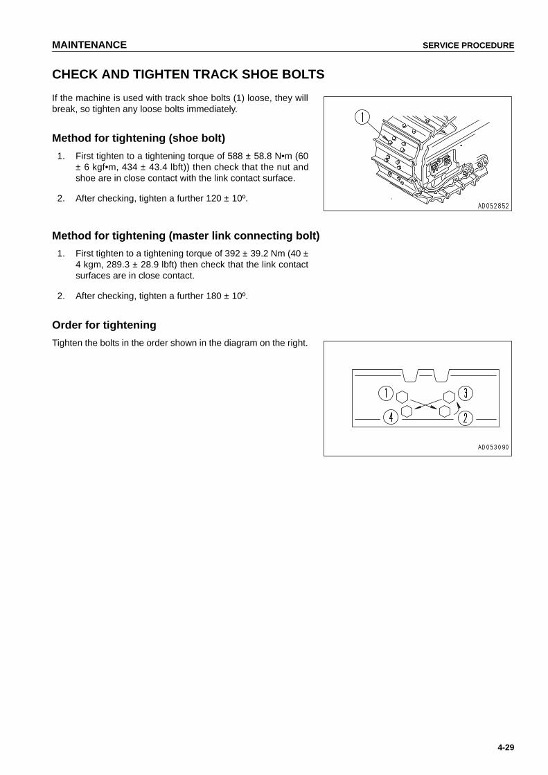
MAINTENANCE SERVICE PROCEDURE
4-29
CHECK AND TIGHTEN TRACK SHOE BOLTS
If the machine is used with track shoe bolts (1) loose, they willbreak, so tighten any loose bolts immediately.
Method for tightening (shoe bolt)
1. First tighten to a tightening torque of 588 ± 58.8 N•m (60± 6 kgf•m, 434 ± 43.4 lbft)) then check that the nut andshoe are in close contact with the link contact surface.
2. After checking, tighten a further 120 ± 10º.
Method for tightening (master link connecting bolt)
1. First tighten to a tightening torque of 392 ± 39.2 Nm (40 ±4 kgm, 289.3 ± 28.9 lbft) then check that the link contactsurfaces are in close contact.
2. After checking, tighten a further 180 ± 10º.
Order for tightening
Tighten the bolts in the order shown in the diagram on the right.
https://tractormanualz.com
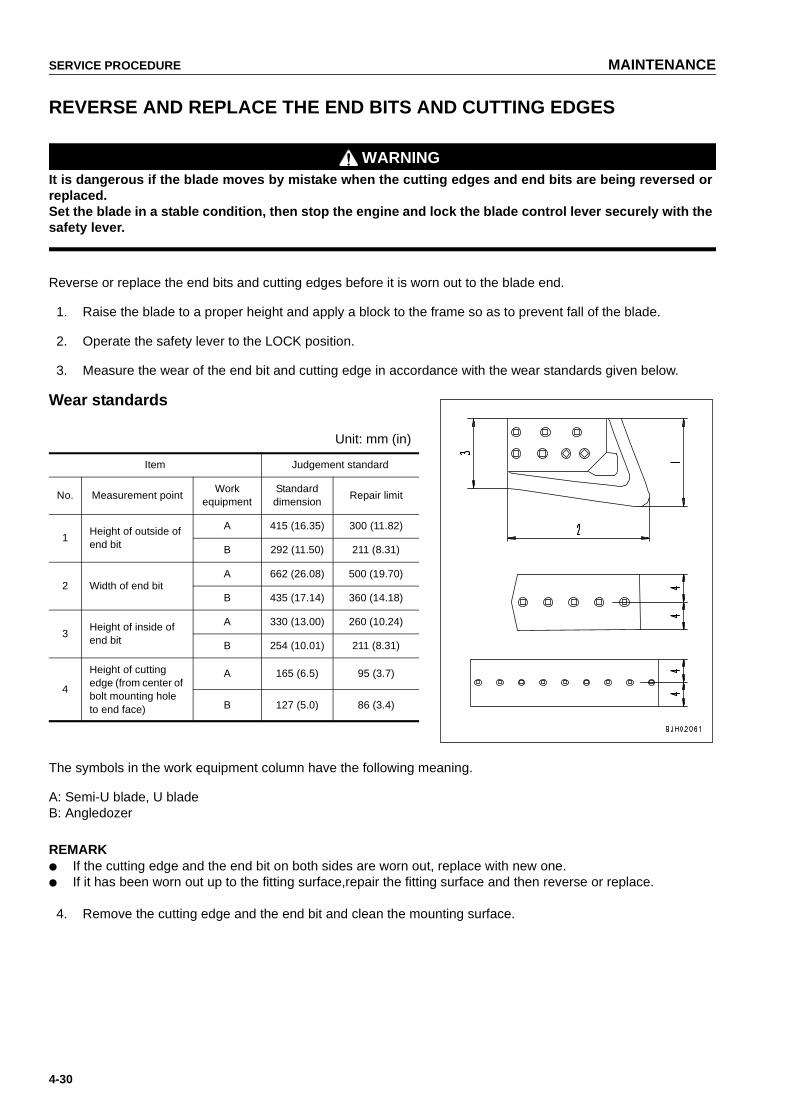
SERVICE PROCEDURE MAINTENANCE
4-30
REVERSE AND REPLACE THE END BITS AND CUTTING EDGES
WARNINGIt is dangerous if the blade moves by mistake when the cutting edges and end bits are being reversed orreplaced.Set the blade in a stable condition, then stop the engine and lock the blade control lever securely with thesafety lever.
Reverse or replace the end bits and cutting edges before it is worn out to the blade end.
1. Raise the blade to a proper height and apply a block to the frame so as to prevent fall of the blade.
2. Operate the safety lever to the LOCK position.
3. Measure the wear of the end bit and cutting edge in accordance with the wear standards given below.
Wear standards
The symbols in the work equipment column have the following meaning.
A: Semi-U blade, U bladeB: Angledozer
REMARK● If the cutting edge and the end bit on both sides are worn out, replace with new one.● If it has been worn out up to the fitting surface,repair the fitting surface and then reverse or replace.
4. Remove the cutting edge and the end bit and clean the mounting surface.
Unit: mm (in)
Item Judgement standard
No. Measurement pointWork
equipmentStandarddimension
Repair limit
1Height of outside of end bit
A 415 (16.35) 300 (11.82)
B 292 (11.50) 211 (8.31)
2 Width of end bitA 662 (26.08) 500 (19.70)
B 435 (17.14) 360 (14.18)
3Height of inside of end bit
A 330 (13.00) 260 (10.24)
B 254 (10.01) 211 (8.31)
4
Height of cutting edge (from center of bolt mounting hole to end face)
A 165 (6.5) 95 (3.7)
B 127 (5.0) 86 (3.4)
https://tractormanualz.com
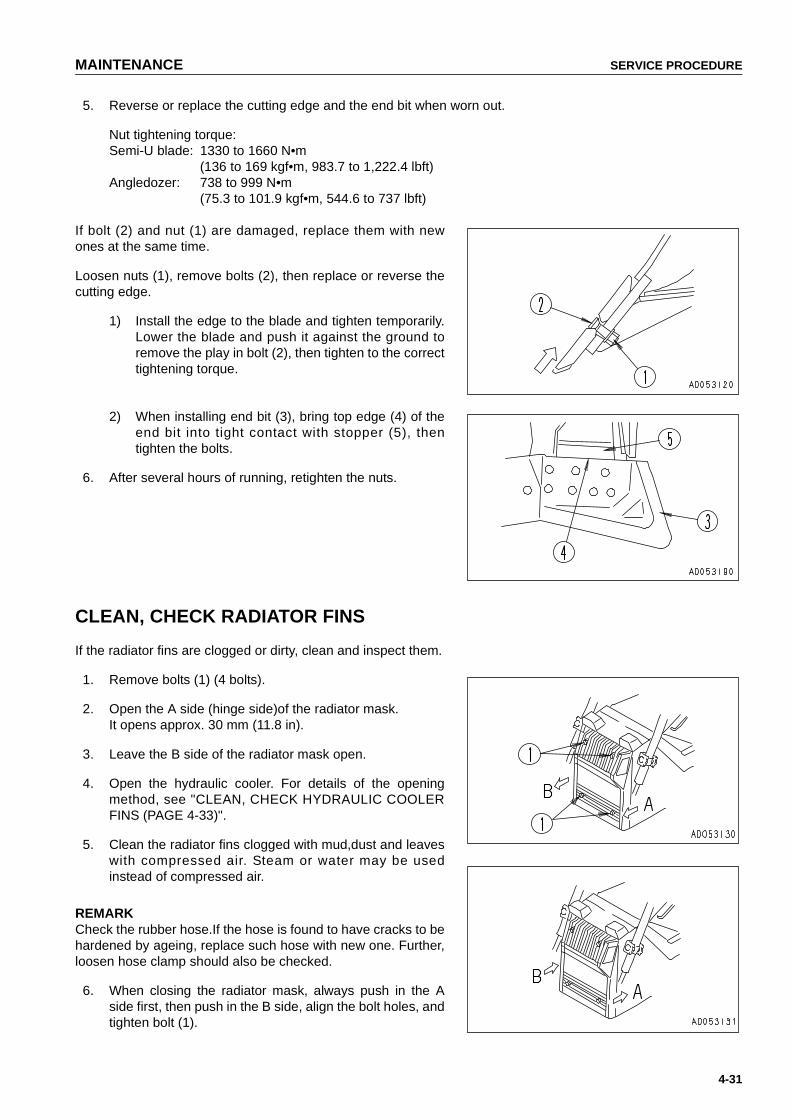
MAINTENANCE SERVICE PROCEDURE
4-31
5. Reverse or replace the cutting edge and the end bit when worn out.
Nut tightening torque:Semi-U blade: 1330 to 1660 N•m
(136 to 169 kgf•m, 983.7 to 1,222.4 lbft)Angledozer: 738 to 999 N•m
(75.3 to 101.9 kgf•m, 544.6 to 737 lbft)
If bolt (2) and nut (1) are damaged, replace them with newones at the same time.
Loosen nuts (1), remove bolts (2), then replace or reverse thecutting edge.
1) Install the edge to the blade and tighten temporarily.Lower the blade and push it against the ground toremove the play in bolt (2), then tighten to the correcttightening torque.
2) When installing end bit (3), bring top edge (4) of theend bit into tight contact with stopper (5), thentighten the bolts.
6. After several hours of running, retighten the nuts.
CLEAN, CHECK RADIATOR FINS
If the radiator fins are clogged or dirty, clean and inspect them.
1. Remove bolts (1) (4 bolts).
2. Open the A side (hinge side)of the radiator mask.It opens approx. 30 mm (11.8 in).
3. Leave the B side of the radiator mask open.
4. Open the hydraulic cooler. For details of the openingmethod, see "CLEAN, CHECK HYDRAULIC COOLERFINS (PAGE 4-33)".
5. Clean the radiator fins clogged with mud,dust and leaveswith compressed air. Steam or water may be usedinstead of compressed air.
REMARKCheck the rubber hose.If the hose is found to have cracks to behardened by ageing, replace such hose with new one. Further,loosen hose clamp should also be checked.
6. When closing the radiator mask, always push in the Aside first, then push in the B side, align the bolt holes, andtighten bolt (1).
https://tractormanualz.com

SERVICE PROCEDURE MAINTENANCE
4-32
REPLACE AIR CONDITIONER BELT
1. Loosen 4 bolts (1) and jack bolt (2), then move compres-sor (3) to the side.
2. Replace the V-belt.
● When adjusting the V-belt, do not push the compres-sor directly with a bar. Use jack bolt (2).
3. Tighten jack bolt (2) and bolts (1), and apply tension tothe V-belt.The standard deflection for the V-belt is approx. 10 mm(0.39 in) when the belt is pushed by thumb (approx. 6 kg(13 lb)) at a point midway between the air compressorpulley and fan pulley.
https://tractormanualz.com

MAINTENANCE SERVICE PROCEDURE
4-33
CLEAN, CHECK HYDRAULIC COOLER FINS
If the hydraulic cooler fins are clogged or there is dirt caught inthe fins, clean and check the fins.
1. Open the radiator mask. For details on how to open theradiator mask, see "CLEAN, CHECK RADIATOR FINS(PAGE 4-31)".
2. Set the hinge pin in position.
1) TopExtend pin bolt (1), and when it penetrates plate (2)(welded to the hydraulic cooler) by 8 mm (0.31 in),set nut (9) in position.
2) BottomExtend pin bolt (4), and when it penetrates plate (5)by 8 mm (0.31 in), set double nut (3) in position.
3. Remove cooler mounting bolts (6) (x 4) and (7) (x 4), andhose clips (8).
4. Open the hydraulic cooler to the hinge side,then cleanand check the fins. The hydraulic cooler can be openedapprox. 40º.
5. Use compressed air to remove the mud,dirt, and leavesclogging the hydraulic cooler fins. Steam or water may beused instead of compressed air.
REMARKInspect the rubber hoses, and replace them if they are crackedor brittle. Check also for loose hose clamps.
6. When fixing the hydraulic cooler in position again:
1) Fix the hydraulic cooler in position with bolts (6) and(7), then fix the hose in position with clamp (8).
2) Retract pin bolts (1) and (4) and set so that there is aclearance of 5 - 10 mm (0.20 - 0.39 in)at the top fromplate (2) and at the bottom from plate (5).
https://tractormanualz.com

SERVICE PROCEDURE MAINTENANCE
4-34
CLEAN, CHECK AIR CONDITIONER CONDENSER FINS
If the air conditioner condenser fins are clogged, clean andcheck the fins.
1. Remove 3 mounting bolts (1) of the upper cover, thenremove upper cover (2).
2. Use compressed air to blow off the mud, dirt, or leavesclogging the fins.
3. Install upper cover (2) with bolts (1).
ADJUST IDLER CLEARANCE
Since the idlers are forced to move forward and backward byan external force, guide plates (2) will be worn out.Wear of these plates will cause the vibration of idlers from sideto side or inclination of the idlers, and running off of track linksfrom the idlers or unevenly worn idler and links may result.Therefore, adjust the idlers according to the following proce-dure.
ADJUSTMENT
1. Drive the machine on level ground for 1 - 2 m (3.28 - 6.56ft), then remove covers (3) (both inside and outside) atthe side face of the idler.
2. Measure the clearance A (4 locations: left, right, insideand outside) between the track frame and the guideplate.
3. If the clearance A exceeds 3.0 mm (0.12 in), loosen bolt(1), and pull out the shim to adjust the clearance at oneend to 0.5 - 1.0 mm (0.02 - 0.04 in).
REMARKThickness of one shim is 1.0 mm (0.04 in).
https://tractormanualz.com

MAINTENANCE SERVICE PROCEDURE
4-35
CHECK UNDERCARRIAGE OIL
Stop the machine on level ground, and check for any reductionin the oil at the idler (portion P), track roller (portion Q), bogieshaft (portion Q), and carrier roller (portion R).
1. Loosen seal bolt (1) slowly and check if oil oozes outfrom the thread. If oil oozes out, the oil level has not gonedown, so tighten the bolt.
2. If no oil comes out even when seal bolt (1) is removed,the oil level is low, so please contact your Komatsu dis-tributor for repair.
REMARK● On the idler, seal bolt (1) cannot be seen unless outside
cover is removed.● There is one bogie shaft seal bolt (1) each on the inside
and outside.
https://tractormanualz.com
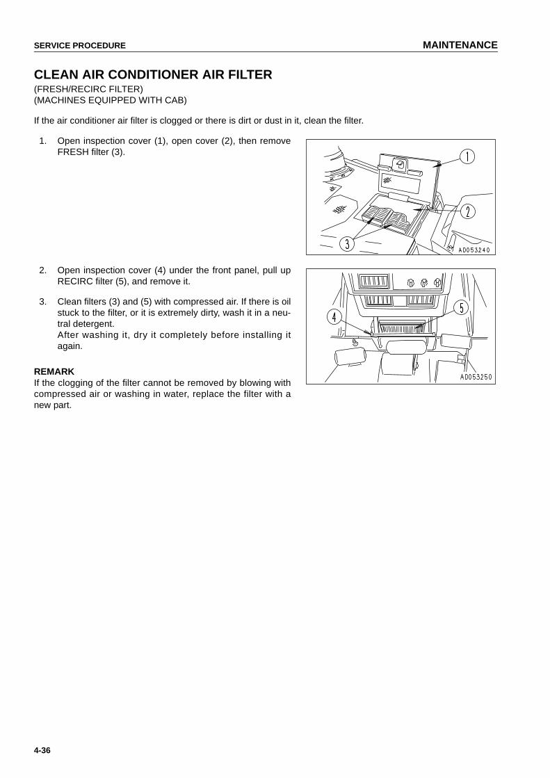
SERVICE PROCEDURE MAINTENANCE
4-36
CLEAN AIR CONDITIONER AIR FILTER(FRESH/RECIRC FILTER)(MACHINES EQUIPPED WITH CAB)
If the air conditioner air filter is clogged or there is dirt or dust in it, clean the filter.
1. Open inspection cover (1), open cover (2), then removeFRESH filter (3).
2. Open inspection cover (4) under the front panel, pull upRECIRC filter (5), and remove it.
3. Clean filters (3) and (5) with compressed air. If there is oilstuck to the filter, or it is extremely dirty, wash it in a neu-tral detergent.After washing it, dry it completely before installing itagain.
REMARKIf the clogging of the filter cannot be removed by blowing withcompressed air or washing in water, replace the filter with anew part.
https://tractormanualz.com

MAINTENANCE SERVICE PROCEDURE
4-37
CHECK, ADJUST AIR CONDITIONER(MACHINES EQUIPPED WITH CAB)
CHECKING TENSION OF COMPRESSOR BELT
If the belt is loose, it will slip and the cooling effect will bereduced. From time to time, press a point midway between thedrive pulley and compressor pulley with your finger (approx.6kg (13 lb)) and check that the tension is 10 mm (0.39 in).When the belt is new, there will be initial elongation, so alwaysadjust again after 2 or 3 days.
CHECK LEVEL OF REFRIGERANT (GAS)
WARNING● When handling refrigerant (gas), always follow local laws and regulations.
● The refrigerant used in the cooler is colorless and odorless and does not harm the atmosphere, but ifthe liquid gets into your eyes or on your hands, it may cause loss of sight or frostbite, so neverloosen any part of the refrigerant circuit.
If the level of the refrigerant (gas) is low, the cooling effect willbe reduced. Run the engine at high idling, and check the flowof the refrigerant in the refrigerant circuit through the sightglass of the receiver when the cooler is running at high speed.
● No bubbles in refrigerant flow: Correct
● Bubbles in refrigerant flow (bubbles continuously passthrough): Refrigerant level low
● Colorless,transparent: No refrigerant
REMARK● When there are bubbles,the refrigerant gas level is low, so
contact your refrigerant dealer to have refrigerant added. Ifthe air conditioner is run with the refrigerant gas level low, itwill cause damage to the compressor.
● New Freon R-134a is used as refrigerant.
https://tractormanualz.com

SERVICE PROCEDURE MAINTENANCE
4-38
GREASE DOOR HINGE(MACHINES EQUIPPED WITH CAB)
If the door makes a squeaking noise when it is opened orclosed, spray lubricant in through the split in the hinge bushing.If the bushing is worn, replace the hinge.
CHECK DOOR LOCK STRIKER(MACHINES EQUIPPED WITH CAB)
If the wear of the doors lock striker exceeds 0.5 mm (0.02 in),replace the striker. If it is used at it is, the play will increase andthis may result in breakage of the hinge or door lock.
https://tractormanualz.com

MAINTENANCE SERVICE PROCEDURE
4-39
CHECK DOOR LATCH
WARNINGIf the control lever is touched by accident during check-ing, the machine moves off suddenly, and this may lead toserious injury or death. Before checking door latch, stop the engine and set theparking lever securely to the LOCK position.
CHECK
Hold the door open-locked, and check that there is still greaseinside the latch. If the amount of grease is low or there is nomore grease, coat the inside of the latch with grease from por-tion (1).
REMARKIf there is no more grease inside the latch, the movement willbecome poor because of dust inside the latch, and the handlemay be stiff when opening the door.
https://tractormanualz.com

SERVICE PROCEDURE MAINTENANCE
4-40
REPLACE DOOR DAMPER(MACHINES EQUIPPED WITH CAB)
If the depth of the door damper rubber groove is less than 2mm (0.08 in), replace the damper.There are two dampers each at the top and bottom on the leftand right doors.
CHECK WINDOW WASHER FLUID LEVEL, ADD FLUID(MACHINES EQUIPPED WITH CAB)
If there is air in the window washer fluid, check the level andadd fluid.Open the battery cover, check the level of the fluid in windowwasher tank (1), and if it is low, add automobile window washerfluid.When adding fluid, be careful not to let dirt or dust get in.
https://tractormanualz.com
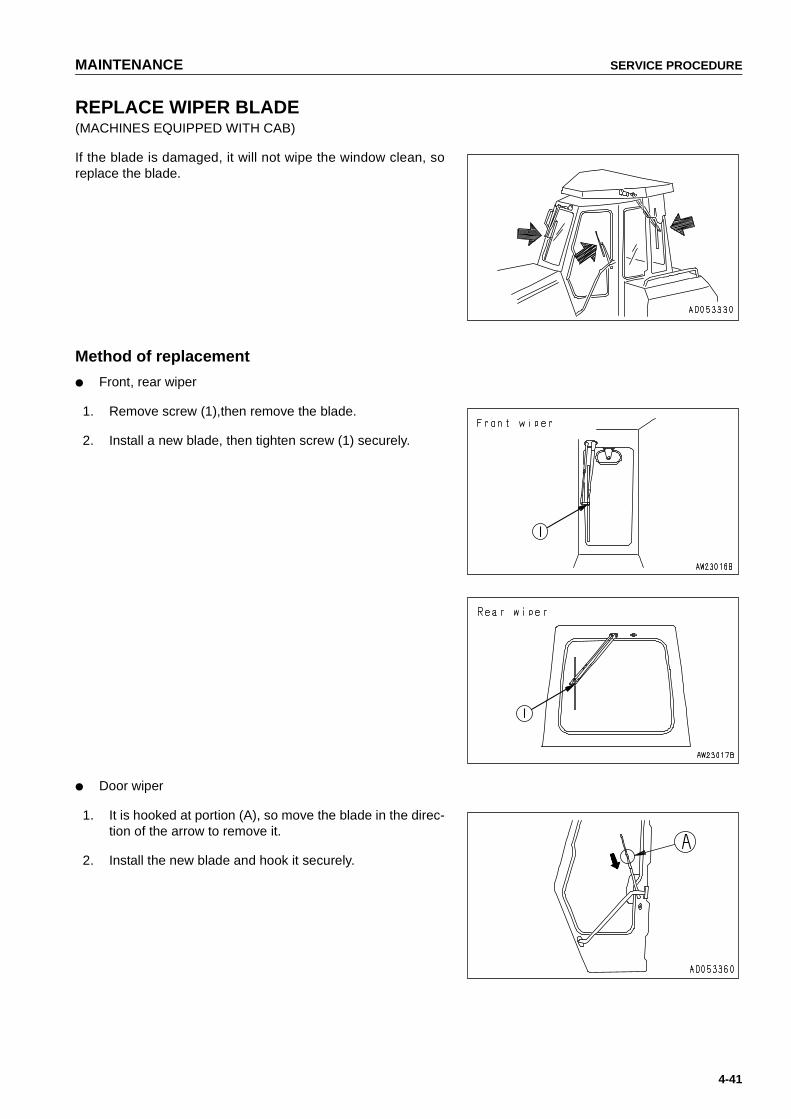
MAINTENANCE SERVICE PROCEDURE
4-41
REPLACE WIPER BLADE(MACHINES EQUIPPED WITH CAB)
If the blade is damaged, it will not wipe the window clean, soreplace the blade.
Method of replacement
● Front, rear wiper
1. Remove screw (1),then remove the blade.
2. Install a new blade, then tighten screw (1) securely.
● Door wiper
1. It is hooked at portion (A), so move the blade in the direc-tion of the arrow to remove it.
2. Install the new blade and hook it securely.
https://tractormanualz.com

SERVICE PROCEDURE MAINTENANCE
4-42
PROCEDURE FOR BLEEDING AIR IN HYDRAULIC SYSTEM
See "STARTING ENGINE (PAGE 3-79)".Since the engine must be started and the blade must be operated, see OPERATION.
NOTICEIf the engine is run immediately at high speed or the cylinder is operated to the end of its stroke, the airinside the cylinder may cause damage to the piston packing.
1. Bleeding air from cylinders
1) Run the engine at low idling, and extend and retract each cylinder 4 to 5 times. Do not operate the cylin-der to the end of its stroke. (Stop at a point approx. 100 mm before the end of the stroke.)
2) Next, operate each cylinder 3 to 4 times to the end of its stroke.
3) Finally, operate each cylinder 4 to 5 times to the end of its stroke to completely remove the air.
PROCEDURE FOR RELEASING INTERNAL PRESSURE OF HYDRAULIC SYSTEM
WARNING● The hydraulic system is always under internal pressure, so when inspecting or replacing the piping or
hoses, always release the pressure in the circuit before starting. If the pressure is not released, highpressure oil may spurt out and cause serious personal injury.
● The parts and oil are at high temperature after the engine is stopped, and may cause serious burns.Wait for the temperature to go down before starting the operation.
● When the oil filler cap is removed, oil may spurt out, so turn the cap slowly to release the pressurebefore removing the cap.
1. Stop the machine on firm level ground.
2. Lower the blde to the ground, then stop the engine.
3. Operate the blade control lever in each direction to thestroke end to release the internal pressure within 15 sec-onds after the engine is stopped.
4. Loosen oil filler cap (F) at the top of the hydraulic tankslowly to release the internal pressure.
5. Run the engine at low idling for about 5 seconds, andstop the engine. Move the blade control lever to back-ward, forward, right and left.
● Repeat step5 2 to 3 times to completely release theremaining pressure.
https://tractormanualz.com
MAINTENANCE SERVICE PROCEDURE
4-43
CHECK BEFORE STARTING
For details of the following items, see "CHECK BEFORE STARTING (PAGE 3-61)" in the OPERATION section.
● Check coolant level, add water
● Checking with machine monitor (Monitor panel specification)
● Check fuel level, add fuel
● Drain water, sediment from fuel tank
● Check oil level in engine oil pan, add oil
● Check oil level in power train case, add oil
● Check brake pedal travel
● Check damper case oil level, add oil
● Check oil level in hydraulic tank, add oil
● Check electric wirings
● Check that lamps light up
● Check horn sound
● Check backup alarm sound
https://tractormanualz.com
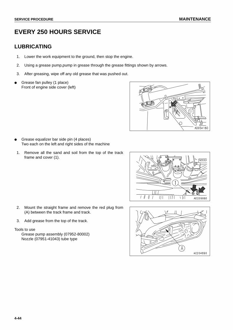
SERVICE PROCEDURE MAINTENANCE
4-44
EVERY 250 HOURS SERVICE
LUBRICATING
1. Lower the work equipment to the ground, then stop the engine.
2. Using a grease pump,pump in grease through the grease fittings shown by arrows.
3. After greasing, wipe off any old grease that was pushed out.
● Grease fan pulley (1 place)Front of engine side cover (left)
● Grease equalizer bar side pin (4 places)Two each on the left and right sides of the machine
1. Remove all the sand and soil from the top of the trackframe and cover (1).
2. Mount the straight frame and remove the red plug from(A) between the track frame and track.
3. Add grease from the top of the track.
Tools to useGrease pump assembly (07952-80002)Nozzle (07951-41043) tube type
https://tractormanualz.com
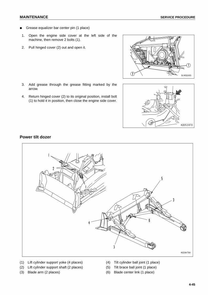
MAINTENANCE SERVICE PROCEDURE
4-45
● Grease equalizer bar center pin (1 place)
1. Open the engine side cover at the left side of themachine, then remove 2 bolts (1).
2. Pull hinged cover (2) out and open it.
3. Add grease through the grease fitting marked by thearrow.
4. Return hinged cover (2) to its original position, install bolt(1) to hold it in position, then close the engine side cover.
Power tilt dozer
(1) Lift cylinder support yoke (4 places) (4) Tilt cylinder ball joint (1 place)(2) Lift cylinder support shaft (2 places) (5) Tilt brace ball joint (1 place)(3) Blade arm (2 places) (6) Blade center link (1 place)
https://tractormanualz.com

SERVICE PROCEDURE MAINTENANCE
4-46
Angledozer
(1) Lift cylinder support yoke (4 places)(2) Lift cylinder support shaft (2 places)(3) Tilt brace thread (2 places)
Ripper
(1) Tilt cylinder bottom pin (2 places)(2) Lift cylinder bottom pin (2 places)(3) Tilt cylinder rod end pin (2 places)(4) Lift cylinder rod end pin (2 places)(5) Arm pin (front) (2 places)(6) Arm pin (rear) (2 places)
https://tractormanualz.com

MAINTENANCE SERVICE PROCEDURE
4-47
CHECK OIL LEVEL IN FINAL DRIVE CASE, ADD OIL
WARNINGThe oil is at high temperature immediately after the machine has been operated. Wait for the oil to cooldown before starting the operation.
1. Stop the machine so that drain plug (1) is directly at thebottom.
2. Remove oil level plug (2) and check whether the finaldrive case is filled with oil to lower edge of the plug hole.
3. If the oil level is low, remove plug (3) and add engine oiluntil it overflows from oil level plug (2).
CHECK LEVEL OF BATTERY ELECTROLYTE
Carry out this check before operating the machine.
WARNING● To avoid gas explosions,do not bring fire or sparks near the battery.
● Battery electrolyte is dangerous.If it gets in your eyes or on your skin, wash it off with large amount ofwater, and consult a doctor.
WHEN CHECKING ELECTROLYTE LEVEL FROM SIDE OF BATTERY
1. Open the battery cover.
2. Remove cap (1), and check that the electrolyte is at thespecified level (10 to 12 mm (0.39 to 0.47 in) above theplate). If the electrolyte level is low, add distilled water tothe specified level.If the battery electrolyte is spilled, have dilute sulphuricacid added.
3. When adding distilled water to any cell at cap (1), adddistilled water also to the other cells.
4. Clean the air hole in the battery cap, then tighten the capsecurely.
NOTICEWhen adding distilled water in cold weather, add it before starting operations in the morning to preventthe electrolyte from freezing.
https://tractormanualz.com
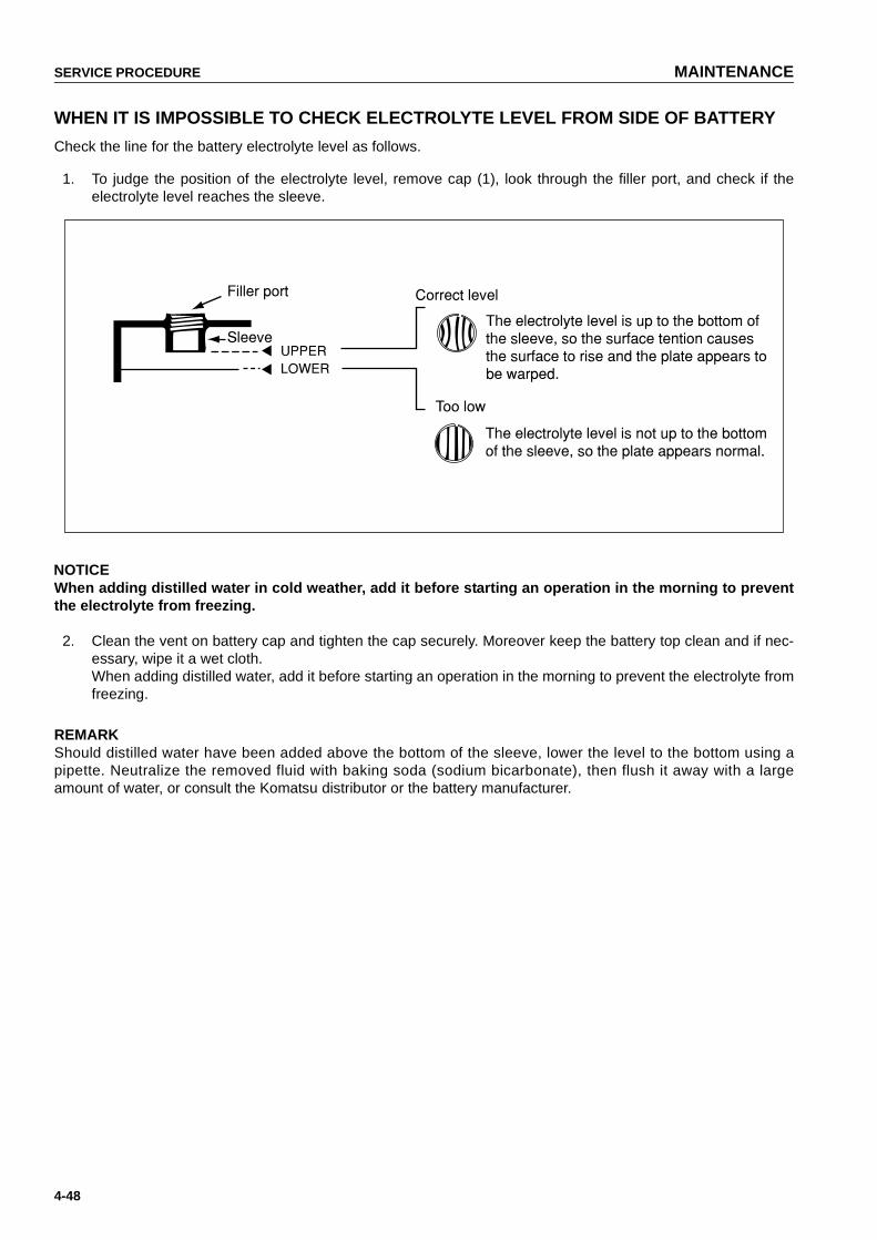
SERVICE PROCEDURE MAINTENANCE
4-48
WHEN IT IS IMPOSSIBLE TO CHECK ELECTROLYTE LEVEL FROM SIDE OF BATTERY
Check the line for the battery electrolyte level as follows.
1. To judge the position of the electrolyte level, remove cap (1), look through the filler port, and check if theelectrolyte level reaches the sleeve.
NOTICEWhen adding distilled water in cold weather, add it before starting an operation in the morning to preventthe electrolyte from freezing.
2. Clean the vent on battery cap and tighten the cap securely. Moreover keep the battery top clean and if nec-essary, wipe it a wet cloth.When adding distilled water, add it before starting an operation in the morning to prevent the electrolyte fromfreezing.
REMARKShould distilled water have been added above the bottom of the sleeve, lower the level to the bottom using apipette. Neutralize the removed fluid with baking soda (sodium bicarbonate), then flush it away with a largeamount of water, or consult the Komatsu distributor or the battery manufacturer.
https://tractormanualz.com
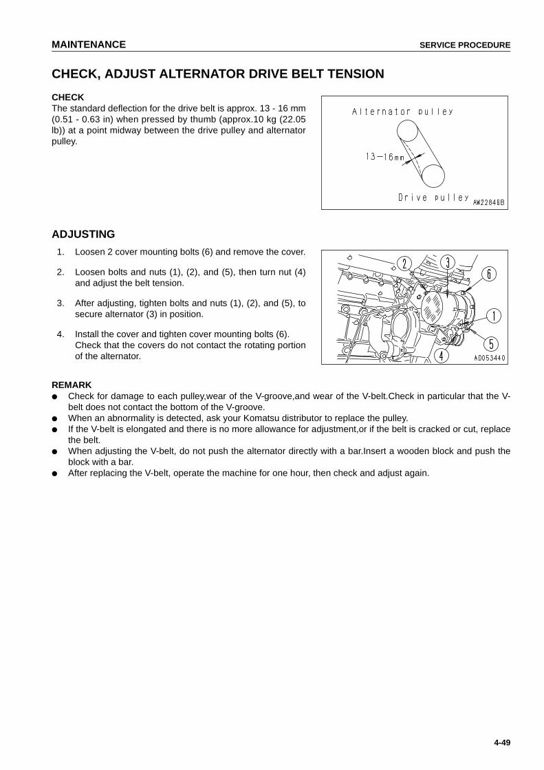
MAINTENANCE SERVICE PROCEDURE
4-49
CHECK, ADJUST ALTERNATOR DRIVE BELT TENSION
CHECKThe standard deflection for the drive belt is approx. 13 - 16 mm(0.51 - 0.63 in) when pressed by thumb (approx.10 kg (22.05lb)) at a point midway between the drive pulley and alternatorpulley.
ADJUSTING
1. Loosen 2 cover mounting bolts (6) and remove the cover.
2. Loosen bolts and nuts (1), (2), and (5), then turn nut (4)and adjust the belt tension.
3. After adjusting, tighten bolts and nuts (1), (2), and (5), tosecure alternator (3) in position.
4. Install the cover and tighten cover mounting bolts (6).Check that the covers do not contact the rotating portionof the alternator.
REMARK● Check for damage to each pulley,wear of the V-groove,and wear of the V-belt.Check in particular that the V-
belt does not contact the bottom of the V-groove.● When an abnormality is detected, ask your Komatsu distributor to replace the pulley.● If the V-belt is elongated and there is no more allowance for adjustment,or if the belt is cracked or cut, replace
the belt.● When adjusting the V-belt, do not push the alternator directly with a bar.Insert a wooden block and push the
block with a bar.● After replacing the V-belt, operate the machine for one hour, then check and adjust again.
https://tractormanualz.com
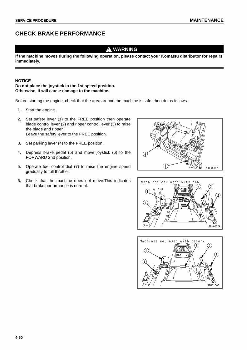
SERVICE PROCEDURE MAINTENANCE
4-50
CHECK BRAKE PERFORMANCE
WARNINGIf the machine moves during the following operation, please contact your Komatsu distributor for repairsimmediately.
NOTICEDo not place the joystick in the 1st speed position.Otherwise, it will cause damage to the machine.
Before starting the engine, check that the area around the machine is safe, then do as follows.
1. Start the engine.
2. Set safety lever (1) to the FREE position then operateblade control lever (2) and ripper control lever (3) to raisethe blade and ripper.Leave the safety lever to the FREE position.
3. Set parking lever (4) to the FREE position.
4. Depress brake pedal (5) and move joystick (6) to theFORWARD 2nd position.
5. Operate fuel control dial (7) to raise the engine speedgradually to full throttle.
6. Check that the machine does not move.This indicatesthat brake performance is normal.
https://tractormanualz.com

MAINTENANCE SERVICE PROCEDURE
4-51
EVERY 500 HOURS SERVICE
Maintenance for every 250 hours service should be carried out at the same time.
REPLACE FUEL FILTER CARTRIDGE
WARNING● After the engine has been operated, all parts are at high temperature, so do not replace the filter
immediately. Wait for all parts to cool down before starting the operation.
● High pressure is generated inside the engine fuel piping system when the engine is running. Whenreplacing the filter, wait for at least 30 seconds after stopping the engine to let the internal pressurego down before replacing the filter.
● Do not bring any fire or flame close.
● Genuine Komatsu fuel filter cartridges use a special filter that has highly efficient filtering ability. When replac-ing the filter cartridge, always use a genuine Komatsu part.
● The common rail fuel injection system used on this machine consists of more precise parts than the conven-tional injection pump and nozzle.If any part other than a genuine Komatsu filter cartridge is used, dust or dirt may get in and cause problemswith the injection system. Always avoid using substitute parts.
● When carrying out inspection or maintenance of the fuel system, pay more attention than normal to the entryof dirt. If dirt is stuck to any part, use fuel to wash it off completely.
● Container to catch the oil
● Filter wrench
1. Set the container to catch the fuel under the filter car-tridge.
● The fuel filter is found by opening the engine sidecover at the left of the machine.
2. Using a filter wrench, turn filter cartridge (1) counterclock-wise to remove it.
3. Clean the filter holder, fill the new filter cartridge withclean fuel, coat the packing surface thinly with engine oil,then install to the filter holder.
NOTICE● When filling with fuel, use clean fuel and be careful not
to let any dirt or dust get in. In particular, the centerarea is the clean side, so be careful not to let dirt ordust get in.
● When filling with fuel, use clean fuel and be careful notto let any dust or dirt get in. Portion (B) at the center isthe clean side, so be particularly careful not to let anydust or dirt get in.
● When adding fuel, always add from small hole (A) ateight places on the dirty side.
● If no clean fuel is available, bleed the air with primingpump (3) without removing the fuel cartridge.
https://tractormanualz.com

SERVICE PROCEDURE MAINTENANCE
4-52
4. When installing, tighten until the packing surface contacts the seal surface of the filter holder, then tighten itup 1/2 to 3/4 of a turn.If the filter cartridge is tightened too far, the packing will be damaged and this will lead to leakage of fuel. Ifthe filter cartridge is too loose, fuel will also leak from the packing, so always tighten to the correct amount.
5. After completion of the replacement of fuel filter cartridge (1), bleed the air.
Bleed the air as follows.6. Add fuel to the fuel tank until full (to FULL mark on the fuel gauge).
7. After replacing filter cartridge (1), loosen air bleed plug (2).
8. Loosen the knob of priming pump (3), move it up and down (90 to 100 times), and continue until no bubblescome out with the fuel.
9. Tighten air bleed plug (2), push in the knob of priming pump (3), then tighten it.Use a genuine Komatsu part for the fuel filter cartridge. After replacing the filter cartridge, run the engine,and check for any leakage of oil from the filter seal surface.
REPLACE POWER TRAIN OIL FILTER ELEMENT
1. Open engine side cover at the left side of the machine,remove bolt (1), then open cover (2) to the outside usingthe hinge at the bottom as the fulcrum.
2. Remove mounting bolt (4) of filter (3), then remove cover(5).
3. Take out element (6).
4. Clean the removed parts and the inside of the case, theninstall a new element.Always use a genuine Komatsu element.
5. Close cover (2), tighten bolt (1), then close engine sidecover on the left side of the machine.
https://tractormanualz.com
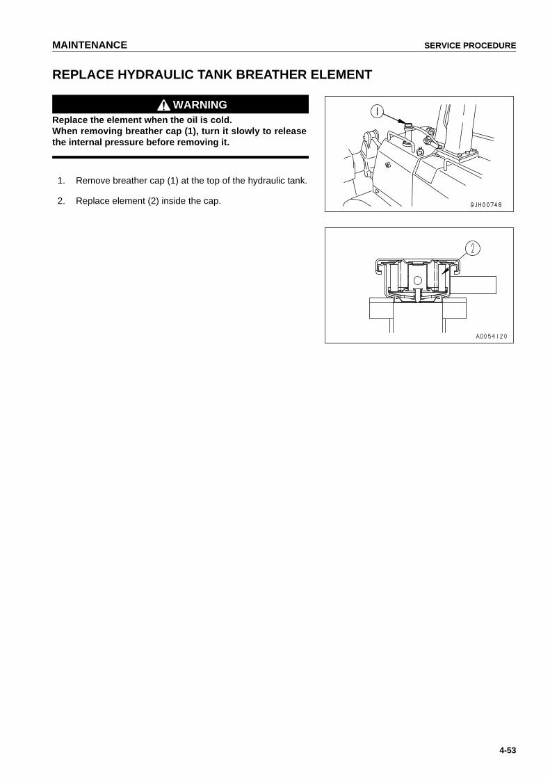
MAINTENANCE SERVICE PROCEDURE
4-53
REPLACE HYDRAULIC TANK BREATHER ELEMENT
WARNINGReplace the element when the oil is cold.When removing breather cap (1), turn it slowly to releasethe internal pressure before removing it.
1. Remove breather cap (1) at the top of the hydraulic tank.
2. Replace element (2) inside the cap.
https://tractormanualz.com

SERVICE PROCEDURE MAINTENANCE
4-54
CHECK AND REPLACE FAN BELT
Check the V-belt and when the following conditions exist,replace the V-belt.
● When the V-belt makes contact with the bottom of thegroove in each pulley.
● When the V-belt is worn, and its surface is lower than theouter diameter of the pulley.
● When cracking and peeling of the V-belt occurs.
A device is installed to maintain the tension constant regard-less of any elongation of the V-belt, so there is no need to carryout adjustment until the V-belt is replaced.
REPLACE● Fit a wrench to the tension pulley, push the pulley in the
direction of the arrow to remove the V-belt, then replacethe V-belt.
● Replace the V-belts as a set.
https://tractormanualz.com

MAINTENANCE SERVICE PROCEDURE
4-55
CHANGE OIL IN ENGINE OIL PAN, REPLACE ENGINE OIL FILTER CARTRIDGE
WARNINGThe oil is at high temperature after the engine has been operated, so never change the oil immediatelyafter finishing operations. Wait for the oil to cool down before changing it.
Prepare the following.
● Refill capacity: 37 (9.77 US gal, 8.14 UK gal)
● Socket wrench, filter wrench.
1. Remove the cover (1) at the bottom of the machine andset a container to catch the oil under the drain plug.
2. To prevent getting oil on yourself, remove drain plug (P)slowly, then loosen drain valve (2) to drain the oil. Do notloosen the drain valve too far, otherwise,the stopper pininside the valve may be deformed.
3. Check the drained oil, and if there are excessive metalparticles or foreign material, please contact yourKomatsu distributor.
4. Install drain plug (P) and drain valve (2) .
Tightening torqueDrain plug (P): 68.6 ± 9.8 N•m
(7 ± 1 kgf•m, 50.6 ± 7.2 lbft)Drain valve (2): 63.7 ± 14.7 N•m
(6.5 ± 1.5 kgf•m, 47.0 ± 10.8 lbft)
5. Using a filter wrench, turn filter cartridge (3) counterclock-wise to remove it. When doing this, to prevent getting oilon yourself, do not carry out this operation from immedi-ately under the cartridge.In particular, if this operation is carried out immediatelyafter stopping the engine, a large amount of oil will comeout, so wait for 10 minutes before starting the operation.
https://tractormanualz.com
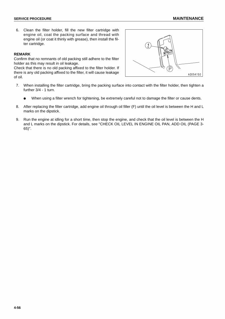
SERVICE PROCEDURE MAINTENANCE
4-56
6. Clean the filter holder, fill the new filter cartridge withengine oil, coat the packing surface and thread withengine oil (or coat it thinly with grease), then install the fil-ter cartridge.
REMARKConfirm that no remnants of old packing still adhere to the filterholder as this may result in oil leakage.Check that there is no old packing affixed to the filter holder. Ifthere is any old packing affixed to the filter, it will cause leakageof oil.
7. When installing the filter cartridge, bring the packing surface into contact with the filter holder, then tighten afurther 3/4 - 1 turn.
● When using a filter wrench for tightening, be extremely careful not to damage the filter or cause dents.
8. After replacing the filter cartridge, add engine oil through oil filler (F) until the oil level is between the H and Lmarks on the dipstick.
9. Run the engine at idling for a short time, then stop the engine, and check that the oil level is between the Hand L marks on the dipstick. For details, see "CHECK OIL LEVEL IN ENGINE OIL PAN, ADD OIL (PAGE 3-65)".
https://tractormanualz.com

MAINTENANCE SERVICE PROCEDURE
4-57
EVERY 1000 HOURS SERVICE
Maintenance for every 250 and 500 hours service should be carried out at the same time.
CHANGE OIL IN POWER TRAIN CASE, WASH STRAINERS(POWER TRAIN PUMP STRAINER, SCAVENGING PUMP STRAINER)
WARNING● The oil is at high temperature immediately after operations, so wait for the temperature to go down
before starting the operation.
● The undercover is heavy.Do not go directly under the cover when opening or closing it. When remov-ing bolts (5), carry out the operation at the rear of the point immediately under the cover so that it ispossible to escape at any time.
Prepare the following.
● Refill capacity: 60 (15.84 US gal, 13.2 UK gal)
1. Remove drain cover (1) at the bottom left of the powertrain case, pull out drain hose (2) from the pick-up port,then loosen drain plug (P1) and drain the oil.After draining the oil, tighten drain plug (P1).Do not remove drain plug (P1).
2. Remove inspection cover (3) in the undercover at thebottom rear of the machine as follows.
1) Remove 2 bolts (4) at the front (front of machine).
2) Hold cover (3) in position and gradually remove 2bolts (5) at the rear (rear of machine). (Rain watermay flow out when doing this.)
3) Lower cover (3) gradually to open it. (The front of thecover is attached by a hinge.)If you look up, you can see the strainer at portion (P).
3. Remove drain plug (P2) in the strainer cover, and drainthe oil (approx. 4 )collected inside the piping.
4. Loosen mounting bolt (6) of the power train strainer, thenremove cover (7).
5. Remove spring (8), then remove strainer (9).
6. Remove any dirt stuck to strainer (9), then wash it inclean diesel oil or flushing oil. Wash the removed partsand the inside of the case at the same time.
https://tractormanualz.com

SERVICE PROCEDURE MAINTENANCE
4-58
7. Loosen mounting bolt (10) of the scavenging pumpstrainer, then remove cover (11).
8. Remove strainer (12).
9. Remove any dirt stuck to strainer (12), then wash it inclean diesel oil or flushing oil. Wash the removed partsand the inside of the case at the same time.
10. Install the strainers to their original positions.
11. Replace the power train filter element.For details, see "REPLACE POWER TRAIN OIL FILTERELEMENT (PAGE 4-52)".
12. Add engine oil through oil filler port (F) to the specifiedlevel.
13. After adding the oil, check that the oil is at the specifiedlevel.For details, see "CHECK OIL LEVEL IN POWER TRAINCASE, ADD OIL (PAGE 3-66)".If the spring or strainer are damaged,replace them withnew parts.
https://tractormanualz.com

MAINTENANCE SERVICE PROCEDURE
4-59
CHANGE OIL IN FINAL DRIVE CASE
WARNINGThe oil is at high temperature immediately after the machine has been operated.Wait for the oil to cooldown before starting the operation.
Prepare the following.
● Refill capacity: each 58 (15.31 US gal,12.76 UK gal)
1. Stop the machine so that drain plug (3) is directly at thebottom.
2. Remove oil level plug (2) and oil filler plug (1), thenremove drain plugs (3) and (4), and drain the oil.Afterdraining the oil, tighten the plugs.
3. Add engine oil to the specified level through the hole in oilfiller plug (1).
4. Check that the oil is at the specified level.For details, see "CHECK OIL LEVEL IN FINAL DRIVECASE, ADD OIL (PAGE 4-47)".
https://tractormanualz.com
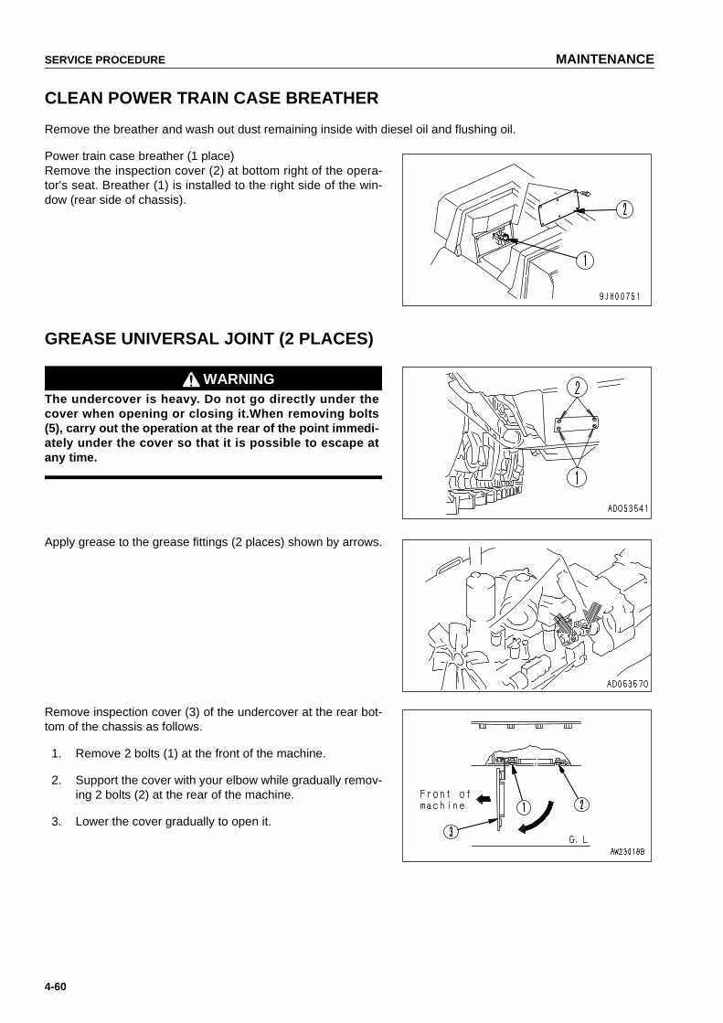
SERVICE PROCEDURE MAINTENANCE
4-60
CLEAN POWER TRAIN CASE BREATHER
Remove the breather and wash out dust remaining inside with diesel oil and flushing oil.
Power train case breather (1 place)Remove the inspection cover (2) at bottom right of the opera-tor's seat. Breather (1) is installed to the right side of the win-dow (rear side of chassis).
GREASE UNIVERSAL JOINT (2 PLACES)
WARNINGThe undercover is heavy. Do not go directly under thecover when opening or closing it.When removing bolts(5), carry out the operation at the rear of the point immedi-ately under the cover so that it is possible to escape atany time.
Apply grease to the grease fittings (2 places) shown by arrows.
Remove inspection cover (3) of the undercover at the rear bot-tom of the chassis as follows.
1. Remove 2 bolts (1) at the front of the machine.
2. Support the cover with your elbow while gradually remov-ing 2 bolts (2) at the rear of the machine.
3. Lower the cover gradually to open it.
https://tractormanualz.com

MAINTENANCE SERVICE PROCEDURE
4-61
REPLACE CORROSION RESISTOR CARTRIDGE
WARNINGThe oil is at high temperature after the engine has been operated, so never replace the cartridge immedi-ately after finishing operations.Wait for the oil to cool down before replacing cartridge.
● Container to catch coolant
● Filter wrench
1. Turn valve (1) of corrosion resistor (2) to the CLOSEstopper position.
2. Set a container under the cartridge to catch the coolant.
3. Using a filter wrench, turn cartridge (2) to the left toremove it.
4. Clean the filter holder, coat the seal surface of the newcartridge thinly with engine oil, then install the cartridge.
● Always use a genuine Komatsu part for the car-tridge.
5. When installing the cartridge, bring the packing surface into contact with the seal surface of the filter holder,then tighten a further 2/3 turn.If the filter cartridge is tightened too far, the gasket will be damaged and water will leak. If it is too loose,water will leak from the gap in the gasket, so always keep to the proper tightening angle.
6. Turn valve (1) of corrosion resistor (2) to the OPEN stopper position.
7. After replacing the cartridge, run the engine, and check for any leakage of water from the filter seal surface.If any water leakage is found, check the tightening of the filter cartridge.
CHECK ALL TIGHTENING PARTS OF TURBOCHARGER
Contact your Komatsu distributor to have the tightening portions checked.
GREASE TENSION PULLEY ASSEMBLY(1 PLACE)
Add grease through the grease fitting until grease comes outfrom the relief valve.
https://tractormanualz.com

SERVICE PROCEDURE MAINTENANCE
4-62
CHECK, CLEAN FUEL STRAINER
1. Tighten fuel supply valve (1) at the bottom of the fueltank, remove cap (2), and wash the strainer and strainercase.The strainer forms one unit with the cap.
2. After checking and cleaning, set the strainer in the case,then tighten cap (2).
3. After installing,open fuel supply valve (1).
https://tractormanualz.com

MAINTENANCE SERVICE PROCEDURE
4-63
REPLACE CHARGE FILTER ELEMENT
1. Loosen mounting bolt (1) and remove inspection cover(2).
2. Loosen mounting bolt (3) and remove filter cover (4).
3. Remove drain plug (P) (which can be seen from underthe fender) and drain the oil.
4. Remove spring (5), then take out element (6) .
5. Clean the removed parts and the inside of filter case (7),then install a new element.Use a genuine Komatsu element.
6. Install inspection cover (2) with bolt (1).
https://tractormanualz.com

SERVICE PROCEDURE MAINTENANCE
4-64
GREASE DLER ADJUSTMENT ROD(LEFT, RIGHT:1 PLACE EACH)
1. Remove bolt (2), then remove cover (1).
2. Add grease through the grease fitting marked by thearrow.
CHECK FOR LOOSE ROPS MOUNT BOLTS(If equipped)
Check for any loose or damaged bolts.If any bolt is loose, tighten to a torque of 926.7 ± 103.0 Nm (94.5 ± 10.5kgm, 683.5 ± 75.9 lbft).If any bolt is damaged, replace it with a genuine Komatsu bolt.
https://tractormanualz.com
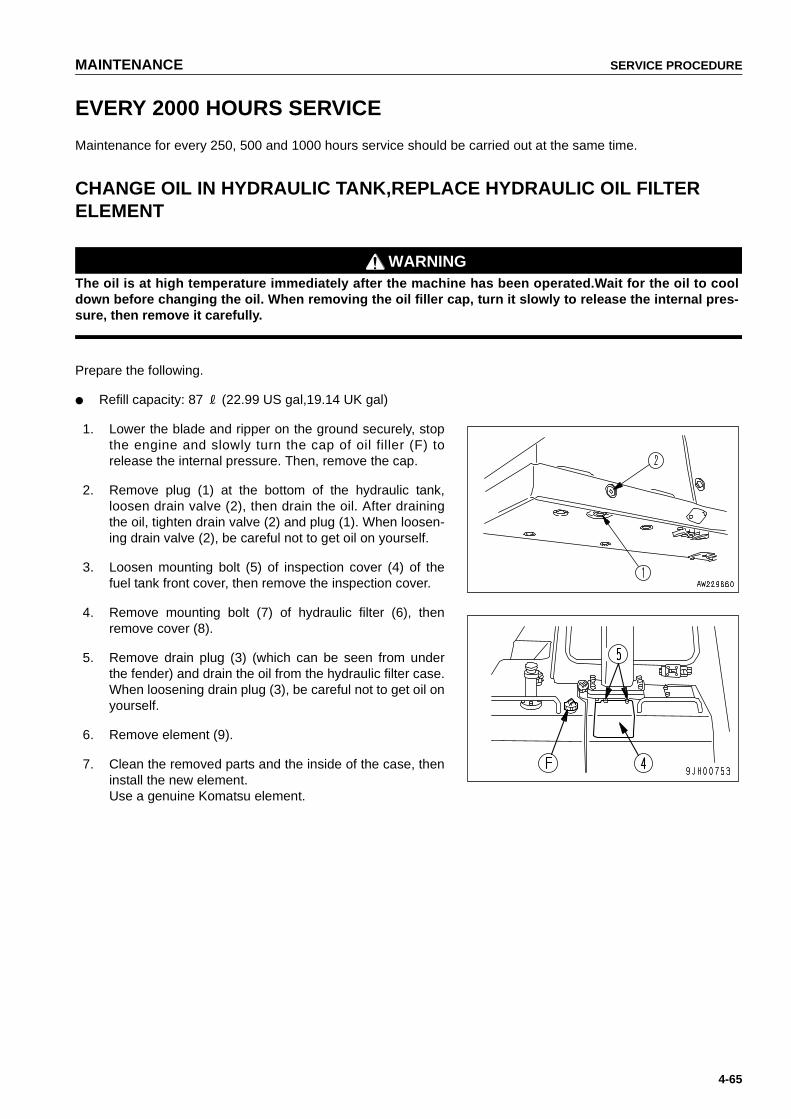
MAINTENANCE SERVICE PROCEDURE
4-65
EVERY 2000 HOURS SERVICE
Maintenance for every 250, 500 and 1000 hours service should be carried out at the same time.
CHANGE OIL IN HYDRAULIC TANK,REPLACE HYDRAULIC OIL FILTER ELEMENT
WARNINGThe oil is at high temperature immediately after the machine has been operated.Wait for the oil to cooldown before changing the oil. When removing the oil filler cap, turn it slowly to release the internal pres-sure, then remove it carefully.
Prepare the following.
● Refill capacity: 87 (22.99 US gal,19.14 UK gal)
1. Lower the blade and ripper on the ground securely, stopthe engine and slowly turn the cap of oil filler (F) torelease the internal pressure. Then, remove the cap.
2. Remove plug (1) at the bottom of the hydraulic tank,loosen drain valve (2), then drain the oil. After drainingthe oil, tighten drain valve (2) and plug (1). When loosen-ing drain valve (2), be careful not to get oil on yourself.
3. Loosen mounting bolt (5) of inspection cover (4) of thefuel tank front cover, then remove the inspection cover.
4. Remove mounting bolt (7) of hydraulic filter (6), thenremove cover (8).
5. Remove drain plug (3) (which can be seen from underthe fender) and drain the oil from the hydraulic filter case.When loosening drain plug (3), be careful not to get oil onyourself.
6. Remove element (9).
7. Clean the removed parts and the inside of the case, theninstall the new element.Use a genuine Komatsu element.
https://tractormanualz.com

SERVICE PROCEDURE MAINTENANCE
4-66
8. Install drain plug (3).
9. Close filter cover (8), then tighten bolt (7).
10. Add engine oil through oil filler port (F) to the specifiedlevel.
11. After adding oil, check that the oil is at the specified level.For details, see "CHECK OIL LEVEL IN HYDRAULICTANK, ADD OIL (PAGE 3-68)".
CHECK PLAY OF TURBOCHARGER ROTOR
Contact your Komatsu distributor to have the play checked.
CLEAN, CHECK TURBOCHARGER
Contact your Komatsu distributor for cleaning or inspection.
CLEAN ENGINE BREATHER ELEMENT
1. Wipe off all the dirt around breather (1).
2. Remove breather (1).
3. Wash the whole breather in diesel oil or flushing oil,thenblow it dry with compressed air.
4. Replace the breather O-ring with a new part, coat withengine oil, and install it.
CHECK ALTERNATOR, STARTING MOTOR
The brush may be worn, or the bearing may have run out of grease, so contact your Komatsu distributor forinspection or repair.If the engine is started frequently,carry out inspection every 1000 hours.
CHECK ENGINE VALVE CLEARANCE, ADJUST
As special tool is required for removing and adjusting the parts, contact your Komatsu distributor for inspection oradjustment.
https://tractormanualz.com

MAINTENANCE SERVICE PROCEDURE
4-67
CHANGE OIL IN DAMPER CASE, CLEAN DAMPER BREATHER
WARNING● The oil is at high temperature immediately after the machine has been operated.Wait for the oil to cool
down before carrying out maintenance.
● The undercover is heavy.Do not go directly under the cover when opening or closing it. When remov-ing bolts (4), carry out the operation at the rear of the point immediately under the cover so that it ispossible to escape at any time.
● Refill capacity 1.5 (0.40 US gal, 0.33 UK gal)
1. Open the engine side cover at the left of the machine;you can see gauge (G).
2. Remove the undercover (2) at the bottom rear of thechassis as follows.
1) Remove 2 bolts (3) at the front of the chassis.
2) Hold cover (1) and gradually remove 2 bolts (4) atthe rear of the chassis. (Be careful when doing this.Rain water may run out.)
3) Lower cover (2) slowly and open it. Drain plug (P)can be seen at the top.
3. Remove dipstick (G), then remove drain plug (P) anddrain the oil.After draining the oil,tighten drain plug (P).
4. Add engine oil through the holder of dipstick (G). Afteradding the oil, insert dipstick (G).
5. Remove any dirt or dust stuck to breather (5), then washwith clean diesel oil or flushing oil.If it cannot be cleanedcompletely, replace with a new part.
https://tractormanualz.com

SERVICE PROCEDURE MAINTENANCE
4-68
6. Install undercover (2), then close engine side cover (1) atthe left side of the machine.
CHECK PIVOT BEARING OIL LEVEL, ADD OIL
1. Remove plug (1).
2. Check that the oil is at the level (25 mm (0.99 in)) in thediagram.If the oil level is low, add engine oil through the hole ofplug (1).
3. Install plug (1).
CHECK INJECTOR
Check the color of the exhaust gasa visually. If there is any abnormally in the exhaust gas color, contact yourKomatsu distributor for inspection.
For details, see "TROUBLESHOOTING (PAGE 3-129)" "Exhaust color is black".
https://tractormanualz.com
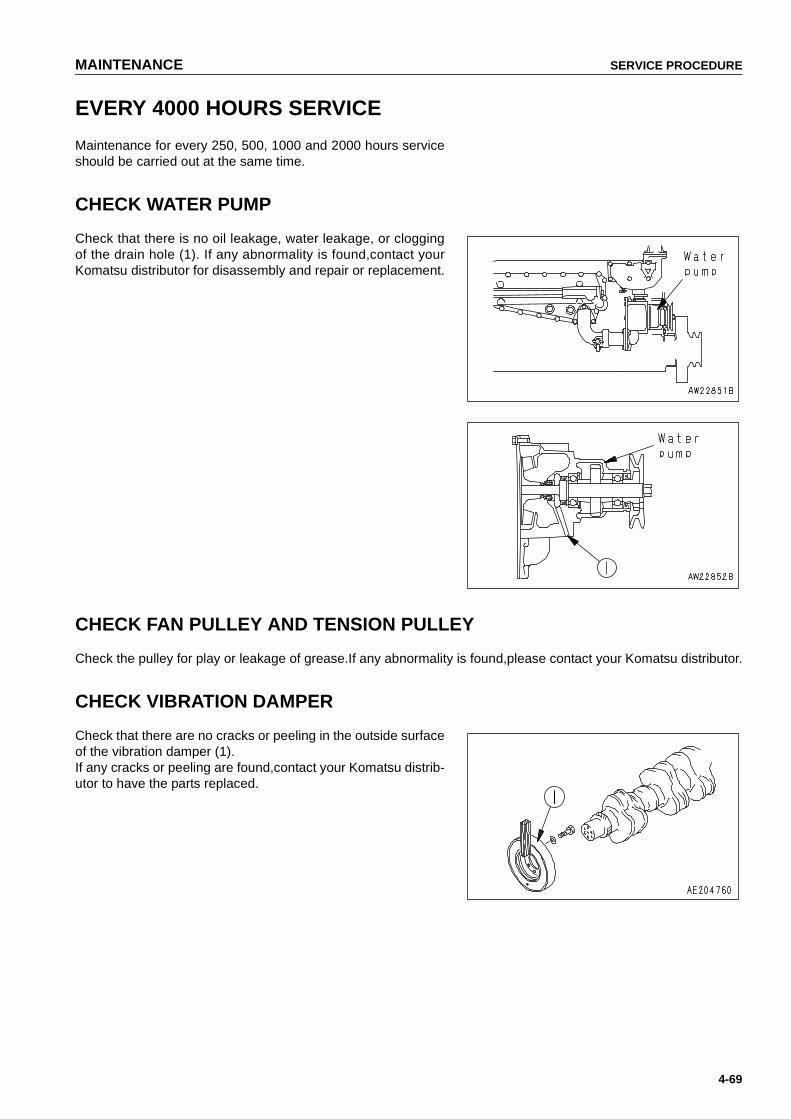
MAINTENANCE SERVICE PROCEDURE
4-69
EVERY 4000 HOURS SERVICE
Maintenance for every 250, 500, 1000 and 2000 hours serviceshould be carried out at the same time.
CHECK WATER PUMP
Check that there is no oil leakage, water leakage, or cloggingof the drain hole (1). If any abnormality is found,contact yourKomatsu distributor for disassembly and repair or replacement.
CHECK FAN PULLEY AND TENSION PULLEY
Check the pulley for play or leakage of grease.If any abnormality is found,please contact your Komatsu distributor.
CHECK VIBRATION DAMPER
Check that there are no cracks or peeling in the outside surfaceof the vibration damper (1).If any cracks or peeling are found,contact your Komatsu distrib-utor to have the parts replaced.
https://tractormanualz.com

SERVICE PROCEDURE MAINTENANCE
4-70
CHECKING FOR LOOSENESS OF HIGH-PRESSURE CLAMP, HARDENING OF RUBBER
Check that there is no looseness in the high-pressure clamp mounting bolts (1) - (15) in the drawing on the nextpage. Check visually and feel with your finger to check that the rubber has not hardened. If there is any problem,the problem part must be replaced. In such a case, please contact your Komatsu distributor.
NOTICEIf the engine continues to be used when there are loose bolts, hardened rubber, or missing parts, there isdanger of damage or breakage occurring due to vibration and wear at the connections of high-pressurepiping. Always check that the proper high-pressure piping clamps are correctly installed.
https://tractormanualz.com
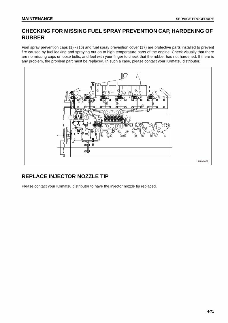
MAINTENANCE SERVICE PROCEDURE
4-71
CHECKING FOR MISSING FUEL SPRAY PREVENTION CAP, HARDENING OF RUBBER
Fuel spray prevention caps (1) - (16) and fuel spray prevention cover (17) are protective parts installed to preventfire caused by fuel leaking and spraying out on to high temperature parts of the engine. Check visually that thereare no missing caps or loose bolts, and feel with your finger to check that the rubber has not hardened. If there isany problem, the problem part must be replaced. In such a case, please contact your Komatsu distributor.
REPLACE INJECTOR NOZZLE TIP
Please contact your Komatsu distributor to have the injector nozzle tip replaced.
https://tractormanualz.com

SERVICE PROCEDURE MAINTENANCE
4-72
EVERY 8000 HOURS SERVICE
Maintenance for every 10, 100, 250, 500, 1000, 2000 and 4000 hours service should be carried out at the sametime.
REPLACE HIGH-PRESSURE PIPING CLAMP
Please contact your Komatsu distributor to have the engine high-pressure clamp replaced.
REPLACE FUEL SPLAY PREVENTION CAP
Please contact your Komatsu distributor to have the fuel spray prevention cap replaced.
https://tractormanualz.com

5-1
SPECIFICATIONS51
https://tractormanualz.com
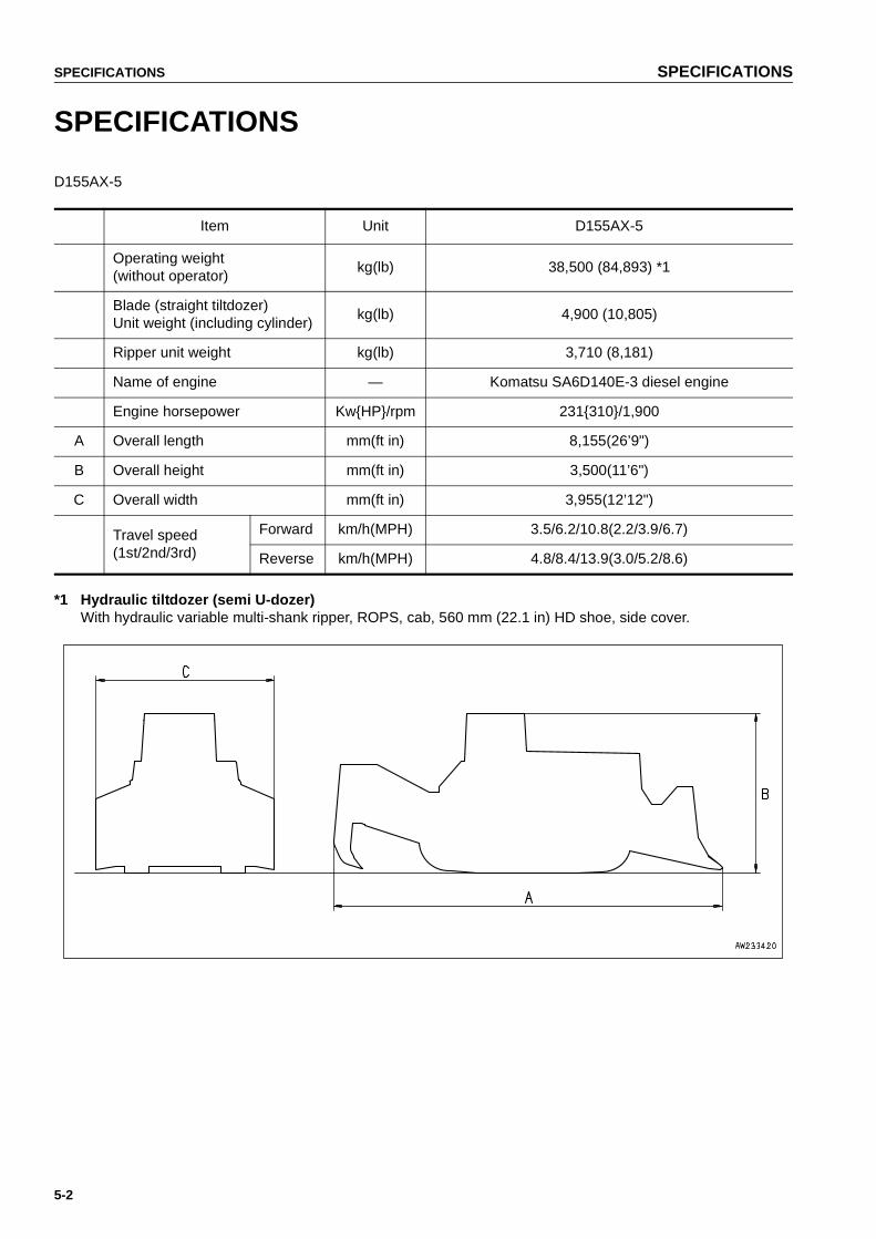
SPECIFICATIONS SPECIFICATIONS
5-2
SPECIFICATIONS
D155AX-5
*1 Hydraulic tiltdozer (semi U-dozer)With hydraulic variable multi-shank ripper, ROPS, cab, 560 mm (22.1 in) HD shoe, side cover.
Item Unit D155AX-5
Operating weight (without operator)
kg(lb) 38,500 (84,893) *1
Blade (straight tiltdozer) Unit weight (including cylinder)
kg(lb) 4,900 (10,805)
Ripper unit weight kg(lb) 3,710 (8,181)
Name of engine — Komatsu SA6D140E-3 diesel engine
Engine horsepower Kw{HP}/rpm 231{310}/1,900
A Overall length mm(ft in) 8,155(26’9")
B Overall height mm(ft in) 3,500(11’6")
C Overall width mm(ft in) 3,955(12’12")
Travel speed (1st/2nd/3rd)
Forward km/h(MPH) 3.5/6.2/10.8(2.2/3.9/6.7)
Reverse km/h(MPH) 4.8/8.4/13.9(3.0/5.2/8.6)
https://tractormanualz.com

6-1
ATTACHMENTSAND
OPTIONS61
4
WARNINGPlease read and make sure that you understand the safetyvolume before reading this section.
https://tractormanualz.com

GENERAL PRECAUTIONS ATTACHMENTS AND OPTIONS
6-2
GENERAL PRECAUTIONS
PRECAUTIONS RELATED TO SAFETY
If attachments or options other than those authorized by Komatsu are installed, this will not only affect the life ofthe machine, but will also cause problems with safety.
When installing attachments not listed in this Operation and Maintenance Manual, contact your Komatsu distribu-tor first.
If you do not contact Komatsu, we cannot accept any responsibility for any accidents or failures.
WARNINGGeneral precautions
● Read the instruction manual for the attachment thoroughly, and do not use this attachment unlessyou are sure that you have understood the guides completely.If you lose the instruction manual, always ask the manufacturer or your Komatsu distributor for a newcopy.
● Depending on the attachment, install the necessary front guard to the machine.
● Depending on the attachment, the impact noise may make it difficult for fellow workers to transmitinstructions for the operation. Before starting operation, decide a leader and determine the signals tobe used.
● When an attachment is installed, the swing range and center of gravity of the machine are different,and the machine may move in an unexpected way. Be sure that you understand the condition of themachine properly.
● Before starting operations, set up a fence around the machine to prevent people from entering.Never operate the machine when there are people near the machine.
● To prevent serious accidents caused by misoperation, do not put your foot on the pedal except whenoperating the pedal.
https://tractormanualz.com

ATTACHMENTS AND OPTIONS GENERAL PRECAUTIONS
6-3
WARNINGPrecautions for removal and installation operations
When removing or installing the attachment, always do as follows to ensure safety in the operation.
● Carry out the removal and installation operation on firm, level ground.
● When carrying out the operation with two or more workers, determine the signals and follow theseduring the operation.
● Always use a crane when you lift or carrying heavy objects (more than 25kg or 55 lb).
● When removing heavy components, always support the component before removing it.When lifting with a crane, be particularly careful about the position of the center of gravity.
● It is dangerous to carry out operations with a load left raised by a crane. Always prepare a stand andensure that the condition is safe.
● When leaving an attachment removed or when installing the attachment, make sure that it is in a sta-ble condition and cannot fall over.
● Never go under a load raised by a crane.Stay in a safe place where there is no danger if the load should fall.
NOTICEQualifications are required to operate a crane. Never allow the crane to be operated by an unqualified per-son.For details of removal and installation operations, contact your Komatsu distributor.
https://tractormanualz.com

INTRODUCTION OF OPTIONAL PARTS AND ATTACHMENTS ATTACHMENTS AND OPTIONS
6-4
INTRODUCTION OF OPTIONAL PARTS AND ATTACHMENTS
INTRODUCTION OF OPTIONAL PARTS AND ATTACHMENTS
Various other optional parts are available, so please contact your Komatsu distributor.
Name Specifications, use
Track shoes
Wide shoe widthWide shoe widthWide shoe widthHeavy-duty shoe widthHeavy-duty shoe width
610 mm (24")660 mm (26")710 mm (28")610 mm (24")660 mm (26")
Ripper point
Reversible fan
Cap with lock
Headrest
https://tractormanualz.com

ATTACHMENTS AND OPTIONS HANDLING HEADREST
6-5
HANDLING HEADREST
Use the headrest with the headrest pushed down to the lowestposition.
https://tractormanualz.com

HANDLING REVERSIBLE FAN ATTACHMENTS AND OPTIONS
6-6
HANDLING REVERSIBLE FAN
REVERSING REVERSIBLE FAN
When reversing the reversible fan in cold weather, do as fol-lows.
1. Loosen bolt (2), then remove cover (1) on the right side ofthe radiator guard. A hold for inserting the tool can beseen.
2. Open engine side cover (3) on the right side of themachine so that the reversing operation can be seen.
3. Insert the tip of the tool into fan blade (4).
4. Push towards the center of the fan, and turn the handle ofthe tool to reverse the fan blades.
5. Reverse 8 fan blades, but rotate the fan as follows.
● Use the starting motor to rotate the fan.
● Loosen the nut of the spring which applies tension to thetension pulley, reduce the belt tension, and rotate by hand.Do not loosen the nut too far or remove it.
● After completely reversing all the fan blades, tighten thenut to its original position.
REMARK● When inserting the tool, if the work equipment or any other
part is in the way, change the position of bolt (5) to extendthe tool when using it.
● If the fan is used in the suction direction in temperaturesbelow -30ºC, it has the effect of heating or maintaining thebattery temperature.
● Use part number 175-900-3910 for the tool.
https://tractormanualz.com
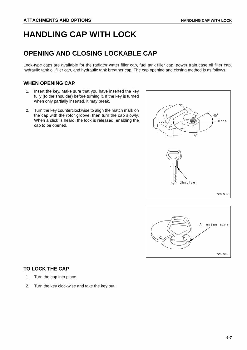
ATTACHMENTS AND OPTIONS HANDLING CAP WITH LOCK
6-7
HANDLING CAP WITH LOCK
OPENING AND CLOSING LOCKABLE CAP
Lock-type caps are available for the radiator water filler cap, fuel tank filler cap, power train case oil filler cap,hydraulic tank oil filler cap, and hydraulic tank breather cap. The cap opening and closing method is as follows.
WHEN OPENING CAP
1. Insert the key. Make sure that you have inserted the keyfully (to the shoulder) before turning it. If the key is turnedwhen only partially inserted, it may break.
2. Turn the key counterclockwise to align the match mark onthe cap with the rotor groove, then turn the cap slowly.When a click is heard, the lock is released, enabling thecap to be opened.
TO LOCK THE CAP
1. Turn the cap into place.
2. Turn the key clockwise and take the key out.
https://tractormanualz.com

PROCEDURE FOR SELECTING RIPPER POINT ATTACHMENTS AND OPTIONS
6-8
PROCEDURE FOR SELECTING RIPPER POINT
PROCEDURE FOR SELECTING RIPPER POINT
https://tractormanualz.com

INDEX
7-1
INDEX
7
AACTION IF FIRE OCCURS .................................2-15ADDITIONAL WORKING LAMP SWITCH ..........3-26ADJUST ANGLE OF BLADE EDGE .................3-115ADJUST ARMREST ............................................3-76ADJUST IDLER CLEARANCE ............................4-34ADJUSTING BEFORE
STARTING OPERATION ...............................3-73ADJUSTING POSTURE OF
WORK EQUIPMENT ....................................3-110ADJUSTING RIPPER ....................................... 3-114ADJUSTING TILT AMOUNT .............................3-111AFTER COLD WEATHER SEASON ................3-127AFTER DAILY WORK COMPLETION ..............3-127AFTER RUNNING OUT OF FUEL .................... 3-129AFTER STARTING ENGINE ..............................3-85AFTER STORAGE ............................................3-128AIR CONDITIONER PANEL ...............................3-15ALARM LAMPS ...................................................3-23ALWAYS APPLY LOCK WHEN
LEAVING OPERATOR'S SEAT .....................2-11ALWAYS USE CLEAN WASHER FLUID ..............4-2AM/FM RADIO ....................................................3-46APPOINT LEADER WHEN
WORKING WITH OTHERS ............................2-29ASHTRAY ...........................................................3-39ATTACHMENTS .................................................2-32AVOID MIXING OILS ............................................4-3
BBATTERY .................................................2-26, 3-126BATTERY CHARGES ....................................... 3-132BATTERY HAZARD PREVENTION ...................2-26BE CAREFUL ABOUT ASBESTOS DUST .........2-18BEFORE STORAGE .........................................3-128BLADE CONTROL LEVER .................................3-33BLADE SERIAL NO. PLATE POSITION ...............1-9BRAKE PEDAL ...................................................3-31BREAKING-IN THE NEW MACHINE ..................3-85
CCARRYING OUT KOWA
(Komatsu Oil Wear Analysis) ............................4-7CAUTION ITEMS ..................................................3-9CHANGE OIL IN DAMPER CASE,
CLEAN DAMPER BREATHER .......................4-67CHANGE OIL IN ENGINE OIL PAN,
REPLACE ENGINE OIL FILTER CARTRIDGE ..................................................4-55
CHANGE OIL IN FINAL DRIVE CASE ...............4-59
CHANGE OIL IN HYDRAULIC TANK,REPLACE HYDRAULIC OIL FILTER ELEMENT ...................................................... 4-65
CHANGE OIL IN POWER TRAIN CASE, WASH STRAINERS ....................................... 4-57
CHASSIS .......................................................... 3-138CHECK AFTER FINISHING WORK ................. 3-105CHECK AFTER INSPECTION AND
MAINTENANCE WORKS ................................ 4-4CHECK AFTER STOPPING ENGINE ................ 3-91CHECK ALL TIGHTENING PARTS OF
TURBOCHARGER ......................................... 4-61CHECK ALTERNATOR, STARTING MOTOR ... 4-66CHECK AND REPLACE FAN BELT ................... 4-54CHECK AND TIGHTEN
TRACK SHOE BOLTS ................................... 4-29CHECK BEFORE STARTING ................... 3-61, 4-43CHECK BEFORE STARTING ENGINE ............. 3-60CHECK BRAKE PERFORMANCE ..................... 4-50CHECK DOOR LATCH ....................................... 4-39CHECK DOOR LOCK STRIKER ........................ 4-38CHECK ELECTRICAL INTAKE AIR HEATER ... 4-27CHECK ENGINE VALVE CLEARANCE,
ADJUST ......................................................... 4-66CHECK FAN PULLEY AND
TENSION PULLEY ........................................ 4-69CHECK FOR LOOSE ROPS MOUNT BOLTS ... 4-64CHECK INJECTOR ............................................ 4-68CHECK LEVEL OF
BATTERY ELECTROLYTE ............................ 4-47CHECK OIL LEVEL IN FINAL DRIVE CASE,
ADD OIL ......................................................... 4-47CHECK PIVOT BEARING OIL LEVEL,
ADD OIL ......................................................... 4-68CHECK PLAY OF
TURBOCHARGER ROTOR ........................... 4-66CHECK SERVICE METER ................................... 4-2CHECK TRACK TENSION ................................. 4-27CHECK UNDERCARRIAGE OIL ........................ 4-35CHECK VIBRATION DAMPER .......................... 4-69CHECK WATER PUMP ...................................... 4-69CHECK WINDOW WASHER FLUID LEVEL,
ADD FLUID .................................................... 4-40CHECK, ADJUST AIR CONDITIONER .............. 4-37CHECK, ADJUST ALTERNATOR DRIVE
BELT TENSION ............................................. 4-49CHECK, CLEAN AND REPLACE
AIR CLEANER ELEMENT ............................. 4-25CHECK, CLEAN FUEL STRAINER .................... 4-62CHECKING FOR LOOSENESS OF
HIGH-PRESSURE CLAMP, HARDENING OF RUBBER ............................ 4-70
https://tractormanualz.com
INDEX
7-2
CHECKING FOR MISSING FUEL SPRAY PREVENTION CAP, HARDENING OF RUBBER .........................................................4-71
CHECKING FOREIGN MATERIALS DRAINED OIL ...................................................4-2
CHECKING SIGNALMAN'S SIGNALS AND SIGNS ....................................................2-18
CHECKS BEFORE OPERATION .......................2-21CHECKS BEFORE STARTING ENGINE ...........2-19CIGARETTE LIGHTER .......................................3-25CLEAN AIR CONDITIONER AIR FILTER ...........4-36CLEAN AIR CONDITIONER
CONDENSER FINS .......................................3-57CLEAN ENGINE BREATHER ELEMENT ...........4-66CLEAN INSIDE OF COOLING SYSTEM ............4-22CLEAN OIL AND GREASE ...................................4-2CLEAN POWER TRAIN CASE BREATHER ......4-60CLEAN, CHECK AIR CONDITIONER
CONDENSER FINS .......................................4-34CLEAN, CHECK HYDRAULIC COOLER FINS ..4-33CLEAN, CHECK RADIATOR FINS .....................4-31CLEAN, CHECK TURBOCHARGER ..................4-66CLEANING AIR FILTER ............................3-57, 3-58CLOTHING AND PERSONAL
PROTECTIVE ITEMS .....................................2-10COLD WEATHER OPERATION .......................3-125COLD WEATHER OPERATION
INFORMATION ............................................3-125COMPRESSED AIR ............................................2-35CONTROL LEVERS, PEDALS, DIAL .................3-28COOLANT .............................................................4-6COOLING OPERATION .....................................3-54COOLING SYSTEM COOLANT .......................3-125CUTTING INTO HARD OR
FROZEN GROUND OR DITCHING .............3-109
DDECELERATION PEDAL ...................................3-31DIGGING UP BOULDERS OR ROCKBED .......3-106DISCHARGED BATTERY .................................3-131DO NOT DISASSEMBLE RECOIL SPRING .......2-33DO NOT DROP THINGS INSIDE MACHINE ........4-3DO NOT GO CLOSE TO
HIGH-VOLTAGE CABLES .............................2-17DOOR POCKET ..................................................3-39DOOR-OPEN LOCK ...........................................3-38DOZING ............................................................3-108DURING STORAGE .........................................3-128DUST INDICATOR ..............................................3-35DUSTY WORKSITES ...........................................4-3
EEFFECTIVE METHOD OF USE .......................3-106ELECTRIC SYSTEM MAINTENANCE .................4-8ELECTRICAL SYSTEM ....................................3-135EMERGENCY STOP ITEMS ..............................3-10EMISSION CONTROL INFORMATION LABEL ....1-9ENGINE ............................................................3-140
ENGINE SERIAL NO. PLATE AND POSITION .... 1-8ENSURE GOOD VISIBILITY .............................. 2-17EVERY 1000 HOURS SERVICE ........................ 4-57EVERY 2000 HOURS SERVICE ........................ 4-65EVERY 250 HOURS SERVICE .......................... 4-44EVERY 4000 HOURS SERVICE ........................ 4-69EVERY 500 HOURS SERVICE .......................... 4-51EVERY 8000 HOURS SERVICE ........................ 4-72EXPLANATION OF COMPONENTS ........... 3-6, 3-46EXPLANATION OF PARTS ................................ 3-41
FFELLING TREES, REMOVING STUMPS ........ 3-109FILTERS ............................................................... 4-8FIRE EXTINGUISHER AND FIRST AID KIT ...... 2-10FIRE PREVENTION ........................................... 2-14FOREWORD ........................................................ 1-2FRONT PANEL ..................................................... 3-7FRONT/REAR, LEFT/RIGHT DIRECTIONS
OF MACHINE ................................................... 1-7FUEL ..................................................................... 4-5FUEL AND LUBRICANTS ................................ 3-125FUEL AND LUBRICANTS TO MATCH
THE AMBIENT TEMPERATURE ..................... 4-4FUEL CONTROL DIAL ....................................... 3-28FUEL STRAINER ................................................. 4-2FUSE BOX .......................................................... 3-36FUSE CAPACITY AND NAME OF CIRCUIT ...... 3-37
GGENERAL PRECAUTIONS ......................... 2-10, 6-2GENERAL VIEW .................................................. 3-2GENERAL VIEW OF CONTROLS AND
GAUGES .......................................................... 3-3GENERAL VIEW OF MACHINE ........................... 3-2GREASE ............................................................... 4-6GREASE DLER ADJUSTMENT ROD ................ 4-64GREASE DOOR HINGE ..................................... 4-38GREASE TENSION PULLEY ASSEMBLY ......... 4-61GREASE UNIVERSAL JOINT (2 PLACES) ....... 4-60GUIDE TO MAINTENANCE ................................. 4-2
HHANDLING ACCUMULATOR ...................2-31, 3-59HANDLING AIR CONDITIONER ........................ 3-54HANDLING CAP WITH LOCK .............................. 6-7HANDLING HEADREST ....................................... 6-5HANDLING HEATER .......................................... 3-58HANDLING HIGH-PRESSURE HOSES ............. 2-34HANDLING REVERSIBLE FAN ........................... 6-6HANDRAILS AND STEPS .................................. 2-12HEATER PANEL ................................................ 3-18HEATING OPERATION ...................................... 3-55HORN SWITCH .................................................. 3-24HOT AND COOL BOX ........................................ 3-39HYDRAULIC SYSTEM - AIR BLEEDING ............. 4-4
https://tractormanualz.com
INDEX
7-3
IIF ABNORMALITIES ARE FOUND .....................2-10IN COLD AREAS ................................................3-88INITIAL 250 HOURS MAINTENANCE ................4-21INSIDE OPERATOR'S COMPARTMENT ...........2-11INSPECTION AND ADJUSTMENT ..................3-117INSPECTION AND REPAIR .............................3-118INSPECTION DURING OFF-SEASON ...............3-56INTRODUCTION ...................................................1-7INTRODUCTION OF OPTIONAL PARTS
AND ATTACHMENTS ......................................6-4IT IS PROHIBITED TO KEEP THE DOOR
OPEN DURING OPERATIONS .................... 3-102IT IS PROHIBITED TO MODIFY THE CAB
GLASS IN ANY WAY THAT WILL OBSTRUCT THE VIEW ...............................3-102
JJOYSTICK ...........................................................3-29
KKEEP MACHINE CLEAN ....................................2-11KEEP WORK PLACE CLEAN AND TIDY ...........2-29KOMATSU GENUINE OILS ..................................4-2KOMATSU GENUINE REPLACEMENTPARTS ...4-2
LLOADING AND UNLOADING .............................2-25LOADING, UNLOADING WORK ......................3-120LOCKING .......................................................... 3-105LONG TERM STORAGE ..................................3-128LOOKING THE INSPECTION COVERS ..............4-4LUBRICATING ....................................................4-44
MMACHINE OPERATION .....................................3-92MACHINE SERIAL NO. PLATE
AND POSITION ................................................1-8MAINTENANCE FOR AIR CONDITIONER ........2-35MAINTENANCE SCHEDURE CHART ...............4-19METER DISPLAY PORTION ..............................3-12METHOD OF ANGLING BLADE .......................3-110METHOD OF LIFTING MACHINE .................... 3-121METHOD OF OPERATING PIN PULLER ........3-107METHOD OF OPERATION .......................3-51, 3-58METHOD OF RELEASING PRESSURE
IN OPERATING CIRCUIT ON MACHINE EQUIPPED WITH ACCUMULATOR ..............3-59
METHOD OF TOWING MACHINE ...................3-130METHOD OF USE ..............................................3-44METHOD OF USING BRAKES .........................3-102MONITOR PANEL ................................................3-7MONITOR RELATED ........................................3-137MOUNTING AND DISMOUNTING .....................2-13MOVING MACHINE OFF ....................................3-92
NNECESSARY INFORMATION ............................. 1-8NO PEOPLE ON ATTACHMENTS ..................... 2-13NO UNAUTHORIZED PERSONNEL
INTO AREA .................................................... 2-31NOISE ................................................................. 2-32NORMAL STARTING ......................................... 3-79NORMAL TURNING ........................................... 3-98
OOIL ........................................................................ 4-5OPENING AND CLOSING LOCKABLE CAP ....... 6-7OPERATE CAREFULLY ON SNOW .................. 2-23OPERATING ON SLOPES ............................... 3-107OPERATION .............................................. 2-21, 3-60OPERATION METHOD .................................... 3-117OPERATIONS AND CHECKS BEFORE
STARTING ENGINE ...................................... 3-77OTHER TROUBLE ........................................... 3-135OUTLINE OF OIL, FUEL, COOLANT ................... 4-5OUTLINE OF SERVICE ....................................... 4-5
PPARKING LEVER ............................................... 3-31PARKING MACHINE ............................... 2-24, 3-103PAY ATTENTION TO GAUGES ....................... 3-101PERIODIC REPLACEMENT OF
SAFETY CRITICAL PARTS .................. 2-35, 4-16PERMISSIBLE WATER DEPTH ....................... 3-101PIN PULLER CONTROL SWITCH ..................... 3-34POSITION OF SERVICE METER ...................... 1-10POSITIONS OF SAFETY PICTOGRAMS ............ 2-5POWER SOURCE .............................................. 3-35PRECAUTION WITH HIGH-PRESSURE OIL .... 2-34PRECAUTIONS FOR ATTACHMENTS ............. 2-16PRECAUTIONS FOR BLIND SPOTS
CAUSED BY CAB STAY AND ROPS STAY ................................................. 3-102
PRECAUTIONS FOR LOADING ...................... 3-120PRECAUTIONS FOR MAINTENENCE .............. 2-29PRECAUTIONS FOR MOVING MACHINE
FORWARD OR IN REVERSE ....................... 2-21PRECAUTIONS FOR OPENING AND
CLOSING ENGINE SIDE COVER ................... 4-3PRECAUTIONS FOR OPERATION ........ 2-19, 3-101PRECAUTIONS FOR TRANSPORTATION ..... 3-122PRECAUTIONS FOR WORK UNDER
MACHINE AND WORK EQUIPMENT ........... 2-32PRECAUTIONS IN COLD AREAS ..................... 2-20PRECAUTIONS ON SLOPES .......................... 3-101PRECAUTIONS RELATED TO SAFETY ............. 6-2PRECAUTIONS WHEN INSTALLING
HYDRAULIC HOSES ....................................... 4-4PRECAUTIONS WHEN STARTING ................... 2-20PRECAUTIONS WHEN TRAVELING ................ 2-22PRECAUTIONS WHEN TRAVELING
UP OR DOWN HILLS .................................. 3-101PRECAUTIONS WHEN USING ................ 3-45, 3-53
https://tractormanualz.com

INDEX
7-4
PRECAUTIONS WHEN USING AIR CONDITIONER .......................................3-56
PRECAUTIONS WHEN USING HAMMER .........2-32PRECAUTIONS WHEN USING
HIGH-PRESSURE GREASE TO ADJUST TRACK TENSION ...........................2-33
PRECAUTIONS WHEN USING ROPS ...............2-15PRECAUTIONS WITH HIGH VOLTAGE ............2-34PRECAUTIONS WITH PRESSURIZED FUEL ...2-34PREVENTION OF BURNS .................................2-14PROCEDURE FOR BLEEDING AIR IN
HYDRAULIC SYSTEM ...................................4-42PROCEDURE FOR RELEASING INTERNAL
PRESSURE OF HYDRAULIC SYSTEM ........4-42PROCEDURE FOR REPLACING RECEIVER ...3-56PROCEDURE FOR SELECTING
RIPPER POINT ................................................6-8PROHIBITION OF DANGEROUS WORK ..........2-23PROPER SELECTION OF FUEL,
COOLANT AND LUBRICANTS ......................4-11PROPER TOOLS ................................................2-31PUSHER OPERATIONS ...................................3-109
RREMOVAL AND
INSTALLATION OF BATTERY ....................3-132REMOVAL OF CAB ..........................................3-123REMOVING BATTERY TERMINAL ....................2-33REPAIR WELDING .............................................2-33REPLACE AIR CONDITIONER BELT ................4-32REPLACE CHARGE FILTER ELEMENT ............4-63REPLACE CORROSION RESISTOR
CARTRIDGE ..................................................4-61REPLACE DOOR DAMPER ...............................4-40REPLACE FUEL FILTER CARTRIDGE ..............4-51REPLACE FUEL SPLAY PREVENTION CAP ....4-72REPLACE HIGH-PRESSURE PIPING CLAMP ..4-72REPLACE HYDRAULIC TANK
BREATHER ELEMENT ..................................4-53REPLACE INJECTOR NOZZLE TIP ...................4-71REPLACE POWER TRAIN OIL
FILTER ELEMENT .........................................4-52REPLACE WIPER BLADE ..................................4-41REVERSE AND REPLACE
THE END BITS AND CUTTING EDGES ........4-30REVERSING REVERSIBLE FAN .........................6-6RIPPER CONTROL LEVER ...............................3-34RIPPER OPERATION .......................................3-106RIPPER SERIAL NO. PLATE POSITION .............1-9ROOM LAMP SWITCH .......................................3-25
SSAFETY ................................................................2-2SAFETY AT WORKSITE ....................................2-16SAFETY CRITICAL PARTS ................................4-17SAFETY FEATURES ..........................................2-11SAFETY INFORMATION ......................................1-5SAFETY LABELS ...........................................2-4, 2-6
SAFETY LEVER ................................................. 3-32SAFETY RULES ................................................. 2-10SASH GLASS INTERMEDIATE LOCK .............. 3-38SERVICE PROCEDURE .................................... 4-21SHIFTING BETWEEN FORWARD AND
REVERSE ...................................................... 3-96SHIFTING GEAR ................................................ 3-95SHIPPING ........................................................... 2-25SMOOTHING NOTICE ..................................... 3-108SPECIFICATIONS ................................................ 5-2STANDARD TIGHTENING TORQUES FOR
BOLTS AND NUTS ........................................ 4-15STARTING ENGINE ..................................2-19, 3-79STARTING ENGINE WITH
BOOSTER CABLES .................................... 3-133STARTING IN COLD WEATHER ....................... 3-81STARTING WITH BOOSTER CABLE ................ 2-27STEERING MACHINE ........................................ 3-98STOP ENGINE BEFORE CARRYING OUT
INSPECTION AND MAINTENANCE ............. 2-30STOPPING ENGINE .......................................... 3-90STOPPING MACHINE ........................................ 3-94STORING OIL AND FUEL .................................... 4-8SWITCH PANEL ................................................. 3-20SWITCHES ......................................................... 3-24
TTABLE OF ENTER SERIAL NO. AND
DISTRIBUTOR ............................................... 1-10TIPS FOR LONGER
UNDERCARRIAGE LIFE ............................. 3-117TOOL BOX ......................................................... 3-40TORQUE LIST .................................................... 4-15TOWING ............................................................. 2-28TRANSPORTATION ................................2-25, 3-120TRAVELING ON SLOPES .................................. 2-23TROUBLESHOOTING ...................................... 3-129TURNING WHILE DESCENDING A SLOPE .... 3-100TWO WORKERS FOR MAINTENANCE
WHEN ENGINE IS RUNNING ....................... 2-30
UUNAUTHORIZED MODIFICATION .................... 2-16USE OF FUEL, COOLANT AND
LUBRICANTS ACCORDING TO AMBIENT TEMPERATURE ........................... 4-11
USING BRAKES ................................................. 2-23USING CAR RADIO ........................................... 3-41USING SEAT BELT ............................................ 3-75
VVENTILATION FOR ENCLOSED AREAS .......... 2-18
WWALK-AROUND CHECK ................................... 3-60WARMING-UP OPERATION .............................. 3-86
https://tractormanualz.com

INDEX
7-5
WARNING TAG ..................................................2-29WASTE MATERIAL ............................................2-35WEAR PARTS ......................................................4-9WEAR PARTS LIST ..............................................4-9WELDING INSTRUCTIONS .................................4-2WHEN REQUIRED .............................................4-22WHEN TOWING .................................................2-28WINDOW WASHER LIQUID ...............................2-15WIPER SWITCH .................................................3-25WORK POSSIBLE USING BULLDOZER .........3-108WORKING ON LOOSE GROUND ......................2-17
https://tractormanualz.com

-8
D155AX-5 BULLDOZER
Form No. SEAM022501P
©2001
All Rights Reserved
Printed in Japan 03-01
https://tractormanualz.com