KODAMA - polimi.it
92
Spirit of the forest KODAMA
Transcript of KODAMA - polimi.it

A spirit in the forestSpirit of the forest
K O D A M A

The name of the pavilion “KODAMA“ is associated with a spirit in the beautiful forest of Arte Sella:
“KO“ of means “tree”, and “DAMA“ means “spirit“ or “sphere“ in Japanese.
Kengo Kuma’s Exhibition, Tokyo, March 2018

A project by:Kengo Kuma Lab
Structural calculations: Ing. Marco Clozza, D3WOOD
Jun Sato, Professor at the University of Tokyo
Prototype: Ing. Marco Clozza, D3WOOD
Ri-legno Srl
CNC works:Ri-legno Srl
Ing. Giulio Franceschini, Project Manager Ri-Legno SrlIng. Lavinia Sartori, Sales Manager Ri-Legno Srl
Arch. Ing. Giorgio Franceschini, Ri-Legno Srl
Politecnico di Milano:Prof. Marco Imperadori, Rector’s Delegate Far East - ABC Department
Prof. Andrea Vanossi, BIM Manager - ABC Department
Federica Iachelini, Architectural - Engineering studentClara Rinaldi, Architectural - Engineering student
Federica Brunone, PhD Candidate ABC Department
University of Tokyo:Toshiki Hirano, Assistant Professor at the University of Tokyo
Takahiro Hirayama, Engineering studentMasumi Ogawa, Engineering student
Ifan Yim(tbc), Engineering student
Material supply:© ROTHO BLAAS SRL
In collaboration with: Arte Sella: the contemporary mountain

C O N C E P T
Kengo Kuma Lab & Toshiki Hirano5th June 2017

Kodama - Project ideas Page 06
Render option 1 - width 200 mm
First Concept Ideas - with bending
Render option 2 - width 100 mm
Render option 2 - width 200 mmRender option 1 - width 300 mm

Kodama - Project ideas Page 07
Render - Last version
Basic unit - measurements
Final Concept Idea - without bending
70
30
1005,8
1515
5,8
Exploded view
Exploded view taken by the Rhino model of the structure.
Received by Toshiki Hirano in date 22th July 2017.

Marco Imperadori, Marco Clozza & D3Wood9th July 2017
K O D A M AMOCKU P 1 :3
M A D E I N L A R C H
Kodama - Node scale 1:3 made in larch Page 09
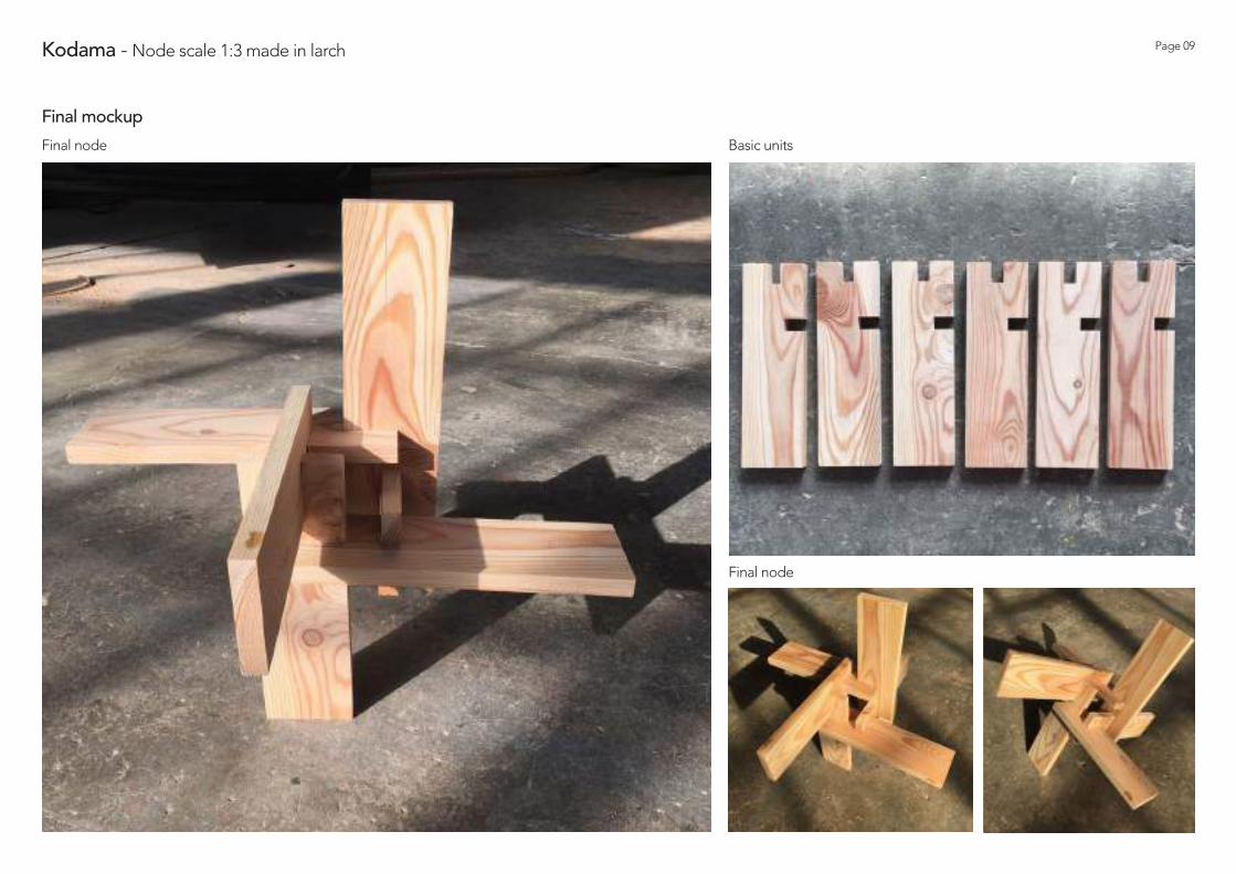
Final node
Basic unitsFinal node
Final mockup

K O D A M AMOCKU P 1 :1
M A D E I N C E D A R
Marco Imperadori, Marco Clozza & D3Wood22nd July 2017

Cutting
Kodama - Node scale 1:1 made in cedar Page 11
Rough boards
MeasurementsCedar trunk section Trunk fixing (creation rectangular section)

Kodama - Node scale 1:1 made in cedar Page 12
Smoothing Smoothing
Smoothed boards
Smoothing - First and second step

Kodama - Node scale 1:1 made in cedar Page 13
Final smoothing Final smoothing Final smoothing
Gathering of wood chips Boards ready to be trimmed
Smoothing - Third step

Kodama - Node scale 1:1 made in cedar Page 14
Boards ready to be carved
Long side trimming Short side trimming
Trimming

Kodama - Node scale 1:1 made in cedar Page 15
Carved boards
Carved detail
Carved detailMarking
Carving - First step

Kodama - Node scale 1:1 made in cedar Page 16
Carved detailManual carvingCarving frameMarking
Carving - Second step
Carving frame

Kodama - Node scale 1:1 made in cedar Page 17
Flatness check
Fixing by means of bolts
Structure base Structure base
Assembling

Kodama - Node scale 1:1 made in cedar Page 18
Checking and fixing the first block
Fixing the first block
Assembling the first block
Assembling

Kodama - Node scale 1:1 made in cedar Page 19
Assembling
Assembling
Construction team
Joint detail

Kodama - Node scale 1:1 made in cedar Page 20
Final nodeFinal node
Final mockup

Arch. Ing. Giorgio Franceschini & Ri-Legno Srl4th September 2017
K O D A M AMOCKU P 1 :1
M A D E I N F I R

Kodama - Node scale 1:1 made in fir Page 22
Due to the fact that we need to work with jointed elements, one of the main problems is the effective slide of the wooden boards that are together connected. Even though the cuts of the different pieces were made with a “CNC machine” there is some error in the joint. The wood milling is often less than 50 mm and doesn’t allow the proper connection till the end of the two pieces.
This problem was temporarily solved widening the wood milling and hitting with an hammer to make the wooden table slide together. This violent impact caused in many points the crepe formation, till the complete break of some of the elements, as you can see in the pictures on the side. The critical points are the one in the corners of the milling, node where the wood has a low traction resistance in the orthogonal direction of the fibres.
To proceed to the construction of the prototype some of the pieces were fixed with glue and some others, the one already positioned, with wood screws.
In order to avoid all this problems it has to be consider a tolerance of 1 mm: the wood boards remain of 50 mm, the milling wood became of 51 mm instead.
Broken board
Checking the width Fixing with screws
Creped board
Fixing with glue
Main issues

Kodama - Node scale 1:1 made in fir Page 23
Challenging has been the assembling of the prototype.
This mockup has been built creating compact blocks of few pieces and than assembling them maintaining a unique direction of all the joints. This decision has been taken due to the fact that, in case of proceeding board by board there is a final point in which the stiffness of the material doesn’t allow the contemporary connection of two joint with orthogonal direction.
This procedure has been possible in this location and with this reduced amount of pieces. In this mockup the elements have been fixed together proceeding with an horizontal direction.
In an executive project this organization would be difficult due to the spherical final shape of the pavilion. Is recommended a vertical growth of the structure and a possible assembling board by board instead of block by block.
Due to the complexity of the model is request a specific building manual for the workers.
Second block assembled Second block assembled
Assembling second block with the first
Main issues

Kodama - Node scale 1:1 made in fir Page 24
CNC machine
CNC machine CNC machine
Final boards
Cutting

Kodama - Node scale 1:1 made in fir Page 25
Connection with the base Connection with the baseAssembling the first boards
Shaving Measurements
Assembling - First block

Kodama - Node scale 1:1 made in fir Page 26
Fixing with the hammer Fixing with the hammer
Fixing with the hammer
Assembling - First block

Kodama - Node scale 1:1 made in fir Page 27
AssemblingAssembling
Assembling - First block

Kodama - Node scale 1:1 made in fir Page 28
Assembling
Assembling - Second block

Kodama - Node scale 1:1 made in fir Page 29
Final mockup - with support
Final mockup

Kodama - Node scale 1:1 made in fir Page 30
Final mockup - without support
Final mockup
Eng. Marco Clozza & D3WoodSince July 2017
K O D A M ACALCULATIONS
F U L L S T R U C T U R E

Page 32Kodama - Calculations, node and entire structure
Calculations reports
Second structural analysis
03 september 2017
D3WOOD via Sant'Ambrogio 48 23900 Lecco cell 3311331530 www.d3wood.it [email protected]
First structural analysis
28 august 2017
D3WOOD via Sant'Ambrogio 48 23900 Lecco cell 3311331530 www.d3wood.it [email protected]
Il carico da neve e l'effetto staccionata
30 agosto 2017
D3WOOD via Sant'Ambrogio 48 23900 Lecco cell 3311331530 www.d3wood.it [email protected]
Calculations reports
Conclusions from the last report
“Starting with 65 mm commercial thickness of slab, after treatment with thicknessing planer, it is possible obtain panels of 57-58mm. This means an important increase of 15% of resistant material. Future step should change the last geometry increasing the thickness in according with panels manufacturer disposition. With new model it will be possible evaluate new strength values in order to decide if it is necessary to introduce new restraints and/or change his positions or only adopt local reinforce. Future analysis will have to provide a more accurate mesh model and as written in the first report it means to arrive at more hight stress values. Future analysis will also consider multi-axial interaction of stress. It is indispensable validate FEA analysis with real stress test.”
Eng. Marco Clozza, D3Wood
Page 33Kodama - Calculations, node and entire structure
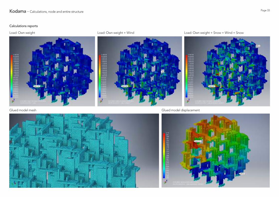
Calculations reports
Load: Own weight
Glued model mesh Glued model displacement
Load: Own weight + Wind Load: Own weight + Snow + Wind + Snow

Page 34
Assembling
Kodama - Calculations, node and entire structure
Calculations - board final thickness 58 mm
Calculations by Eng. Marco Clozza, D3Wood

D3 Wood, Federica Iachelini & Clara Rinaldi24th January 2018
K O D A M AL O A D T E S T
N O D E 1 : 1 I N L A R C H

Page 41Kodama - Load test node 1:1 in Larch
Used tools

Page 42Kodama - Load test node 1:1 in Larch
Base wood units
1
Static Scheme
6
7
8
9
10
3
4
5
2
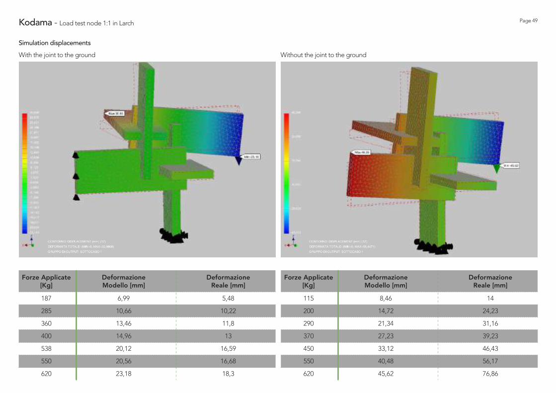
The load tests have been set up following two different static schemes. The first set up uses a restraint opposite to the point of the pulling force and the second set up uses only a fixed support to the ground. The first test is the best simulation of the reality, with the second restraint to the ground. In fact, in the second case the force turns out to be too eccentric and the resistance to compression of the element needs to be reduced. The tools used in the tests are listed and showed below.
1. Fixing ring for the joint to the ground 2. Metal tightener 3. Metal bracket (dimensions’ plates 6x14 cm. ) 4. Holes for the ground connection of the larch board5. Planed larch board, dim. 78x30x5,8 cm. 6. Steel ground bracket for the attachment to the ground7. Pulley to transfer the force 8. Centesimal comparator to measuere the vertical movement 9. Pulling rope10. Dynamometer 2,5 ton hung on the bridge crane to measure the pulling force
First Static Scheme

Page 43Kodama - Load test node 1:1 in Larch
Steel ground bracket fixed to land

Page 44Kodama - Load test node 1:1 in Larch
Assembling the node

Page 45Kodama - Load test node 1:1 in Larch
Elements for the Junction System

Page 46Kodama - Load test node 1:1 in Larch
Pulling System components

Page 47Kodama - Load test node 1:1 in Larch
Load Tests

Page 48Kodama - Load test node 1:1 in Larch
Conclusions and comparisonsThe observations made by engineer Marco Clozza during the load tests and the eventually drawn conclusions will be discusses in the following.
“The results of the tests are very positive for different aspects:
1. There is a good correlation of stress and deformation between the FEM analysis and the reality. Initially the reached displacement was higher than the one calculated due to the recovery of the tolerance of 3/10 of the joints, instead closer to the breaking point the real displacement was lower than the calculated.
2. Before arriving to the break point, with 7 kN of pulling, the knot has remarkable reserves of plastification. The software at 6 kN of pulling calculates values of stress of at least an higher order than those we have in the global model with real forces at ULS.
3. In case of centred force (Static Scheme 1), at the first break point with more than 7kN of pulling force, the hyperstaticity reserves influence the result and the dynamometer revealed still 4 kN of pulling.”
Load Test - Scheme 1In the preceding page is reported the final image of the knot at the breaking point is presented (Load Test - Scheme 1) of which on the right the graphic Force versus Displacement. In this case the breaking force is 7 kN circa: the last recorded value that is measured is an imposed force of 6,2 kN after which it verified a peak of force of 7,3 kN with the consequence of breaking the larch board.
Load Test - Scheme 2In the second test it was expected to measure a lower breaking force, due to the lack of the restraint and the consequent force’s eccentricity. The node broke at 8,5 kN, indicating a better resistance to compression of the element. This test shows a more fragile type of break: it happened without the verifying of all the plastic deformation, stood out in the first in hyperstatic configuration.
First Cycle Displacement Second Cycle Displacement
Forc
e [k
N]
Displacement [mm]
7
6
5
4
3
2
1
00 20 40 60 80
First Cycle Displacement
Forc
e [k
N]
Displacement [mm]
7
6
5
4
3
2
1
00 8020 40 60
Page 49Kodama - Load test node 1:1 in Larch
Simulation displacements
With the joint to the ground Without the joint to the ground
187
285
360
400
538
550
620
Forze Applicate [Kg]
Deformazione Modello [mm]
Deformazione Reale [mm]
6,99
10,66
13,46
14,96
20,12
20,56
23,18
5,48
10,22
11,8
13
16,59
16,68
18,3
115
200
290
370
450
550
620
Forze Applicate [Kg]
Deformazione Modello [mm]
Deformazione Reale [mm]
8,46
14,72
21,34
27,23
33,12
40,48
45,62
14
24,23
31,16
39,23
46,43
56,17
76,86

K O D A M AMOCKU P 1 :5
M A D E I N Y E W
Marco Imperadori, Marco Clozza & D3Wood20th October 2017

Page 50Kodama - Node scale 1:5 made in yew
Node detail Separate elements to compose
Delivery of the mockup to Kengo Kuma
Separate elements to compose
Final mockup

D3Wood, Federica Iachelini & Clara Rinaldi4th April 2018
K O D A M AMOCKU P 1 :5
M A D E I N O A K

Page 52Kodama - Mockup 1:5 made in Oak
Pieces’ classification and realization of the first ring
Oak mockup realized in D3Wood laboratory
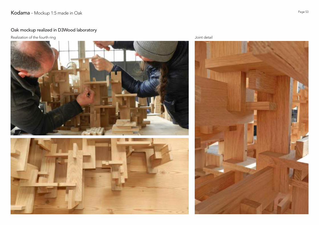
Page 53Kodama - Mockup 1:5 made in Oak
Realization of the fourth ring Joint detail
Oak mockup realized in D3Wood laboratory

Page 54Kodama - Mockup 1:5 made in Oak
Final mockup
Oak mockup realized in D3Wood laboratory

Page 55Kodama - Mockup 1:5 made in Oak
Oak mockup located in Villa Strobele garden
Final mockup

Marco Imperadori & Kuma-LAB15th November 2017
K O D A M AM OCKU P 1:10
M A D E I N P O L I P L AT
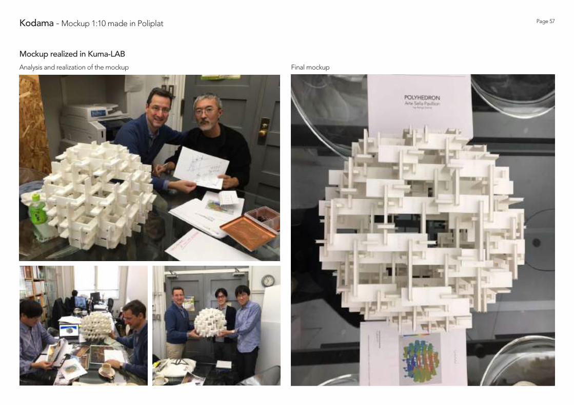
Page 57Kodama - Mockup 1:10 made in Poliplat
Analysis and realization of the mockup Final mockup
Mockup realized in Kuma-LAB

Page 58Kodama - Mockup 1:10 made in Poliplat
Insertion in real context
Mockup realized in Kuma-LAB
Federica Iachelini & Clara Rinaldi15th April 2018
K O D A M AMOCKUP 1:20
M A D E I N M E T H A C R Y L AT E

Page 60Kodama - Mockup 1:20 made in Methacrylate
Final mockup
Final mockup located in Villa Strobele garden

Arch. Ing. Giorgio Franceschini & Ri-Legno Srl4th April 2018
K O D A M AO N - S I T E
ELEMENTS’ PRODUCTION

Kodama - Elements’ production Page 62
Final codes and excel organization file Piece Type Code PackageAll the model was codified following precise rules. First of all every pieces was classified for type with a number. Secondly to each one was assigned a specific, unique numerical and alphabetical code.
PEZZO TIPO NOMENCLATURA MONTAGGIO PACCO DI CARICO127.0 1-10YZ FAB_L0132.0 1-11YZ FAB_L0132.0 1-1YZ FAB_L0133.0 1-2YZ FAB_L01113.0 1-3XY FAB_L0135.0 1-4ZX FAB_L015.0 1-5ZX FAB_L01128.0 1-6YZ FAB_L01105.0 1-7XY FAB_L0133.0 1-8YZ FAB_L01115.0 1-9ZX FAB_L018.0 2-10XY FAB_L028.0 2-11YZ FAB_L02148.0 2-12XY FAB_L028.0 2-13ZX FAB_L028.0 2-14ZX FAB_L0293.0 2-15YZ FAB_L028.0 2-16XY FAB_L02154.0 2-17YZ FAB_L0247.0 2-18XY FAB_L02147.0 2-19ZX FAB_L0293.0 2-1YZ FAB_L0210.0 2-20YZ FAB_L0211.0 2-21YZ FAB_L028.0 2-2XY FAB_L0268.0 2-3ZX FAB_L028.0 2-4YZ FAB_L02141.0 2-5XY FAB_L0255.0 2-6ZX FAB_L028.0 2-7ZX FAB_L028.0 2-8ZX FAB_L0265.0 2-9YZ FAB_L0210.0 3-10YZ FAB_L03114.0 3-11ZX FAB_L038.0 3-12ZX FAB_L034.0 3-13ZX FAB_L03142.0 3-14ZX FAB_L0366.0 3-15YZ FAB_L0358.0 3-16YZ FAB_L038.0 3-17XY FAB_L03102.0 3-18YZ FAB_L035.0 3-19XY FAB_L03152.0 3-1YZ FAB_L0342.0 3-20YZ FAB_L03143.0 3-21XY FAB_L038.0 3-22YZ FAB_L03104.0 3-23XY FAB_L0310.0 3-24YZ FAB_L038.0 3-25ZX FAB_L035.0 3-26ZX FAB_L038.0 3-27ZX FAB_L03
PEZZO TIPO NOMENCLATURA MONTAGGIO PACCO DI CARICO127.0 1-10YZ FAB_L0132.0 1-11YZ FAB_L0132.0 1-1YZ FAB_L0133.0 1-2YZ FAB_L01113.0 1-3XY FAB_L0135.0 1-4ZX FAB_L015.0 1-5ZX FAB_L01128.0 1-6YZ FAB_L01105.0 1-7XY FAB_L0133.0 1-8YZ FAB_L01115.0 1-9ZX FAB_L018.0 2-10XY FAB_L028.0 2-11YZ FAB_L02148.0 2-12XY FAB_L028.0 2-13ZX FAB_L028.0 2-14ZX FAB_L0293.0 2-15YZ FAB_L028.0 2-16XY FAB_L02154.0 2-17YZ FAB_L0247.0 2-18XY FAB_L02147.0 2-19ZX FAB_L0293.0 2-1YZ FAB_L0210.0 2-20YZ FAB_L0211.0 2-21YZ FAB_L028.0 2-2XY FAB_L0268.0 2-3ZX FAB_L028.0 2-4YZ FAB_L02141.0 2-5XY FAB_L0255.0 2-6ZX FAB_L028.0 2-7ZX FAB_L028.0 2-8ZX FAB_L0265.0 2-9YZ FAB_L0210.0 3-10YZ FAB_L03114.0 3-11ZX FAB_L038.0 3-12ZX FAB_L034.0 3-13ZX FAB_L03142.0 3-14ZX FAB_L0366.0 3-15YZ FAB_L0358.0 3-16YZ FAB_L038.0 3-17XY FAB_L03102.0 3-18YZ FAB_L035.0 3-19XY FAB_L03152.0 3-1YZ FAB_L0342.0 3-20YZ FAB_L03143.0 3-21XY FAB_L038.0 3-22YZ FAB_L03104.0 3-23XY FAB_L0310.0 3-24YZ FAB_L038.0 3-25ZX FAB_L035.0 3-26ZX FAB_L038.0 3-27ZX FAB_L03
Each type of piece had a related number and was assigned to a specific stock pallet (corresponding to the structural ring).
Ring number Assembling order
Piece orientation
1-10YZ
Model codification

Kodama - Elements’ production Page 63
Original boards in larchCutting
CNC machine
Final boards

D3Wood, Federica Iachelini & Clara Rinaldi16-20th April 2018
K O D A M AO N - S I T E
CONSTRUCTION IN LARCH

Page 64Kodama - On-site construction
The pavilion’s building had been based on a strict assembling scheme that stem from the study of the parametric model. Kodama is composed by 335 panels characterized by bidirectional joints; this complex geometry requires a construction organized by phases.
Through “a rings scheme” the realization of the entire pavilion was allowed. This procedure provide a separate mounting of each ring that is jointed to the precedent in a second moment. For this reason, the parametric model has been subdivided in 10 different, connected between each other following only the vertical direction.
This model dissection facilitated the structural phases of the entire work and was also extremely useful for the construction-site organization. The 335 larch pieces cut by the CNC machine (RiLegno Srl) have been stocked on 5 different pallet according to the parametric model codes.
The Kodama construction lasted 5 days (from 16th to 20th of April 2018). The first one has been used to place the foundations beams made in larch and to fix the metal plates. The wood structure, completely jointed without any metal connections, started on the 17th of April 2018 and continued for 4 days.
First, second, third and fourth ring
Eighth and ninth ring
Fifth, sixth and seventh ring
Tenth ring
Construction-book
Day 2 - 17th April
Day 4 - 19th April
Day 3 - 18th April
Day 5 - 20th April

Page 65Kodama - On-site construction
Placement of the root beams
Day 1 - 16th April

Page 66Kodama - On-site construction
Placement of the metal plates
Day 1 - 16th April

Page 67Kodama - On-site construction
Realization of the first and second ring
Day 2 - 17th April

Page 68Kodama - On-site construction
Realization of the third and fourth ring
Day 2 - 17th April

Page 69Kodama - On-site construction
Realization of the fifth ring
Day 3 - 18th April

Page 70Kodama - On-site construction
Realization of the sixth and seventh ring
Day 3 - 18th April

Page 71Kodama - On-site construction
Realization of the eighth and ninth ring
Day 4 - 19th April

Page 72Kodama - On-site construction
Final pavilion
Day 5 - 20th April

Page 73Kodama - On-site construction
Detail
Day 5 - 20th April

Page 74Kodama - On-site construction
Federica, Claudio, Marco and Clara
Day 5 - 20th April

S T E P P I N G S T O N E S S T R O B E L E H O U S E G A R D E N
Marco Imperadori, Federica Iachelini & Clara Rinaldi18th January 2018

Page 76Stepping Stones - Inspirations and materials
The stone path: Stepping Stones
As the tradition wants, the stone path begins from the tea hall (Chashitsu), sacred room where the Cha No Yo, tea ceremony, takes place.
The sacredness of this ceremony imposes that also the approach to the hall follows a specific rules. The so-called Stepping Stones begins in front of the entrance of the hall, where there is positioned the biggest stone of the path. This element represents the point of division and connection between the sacred hall and the garden, a kind of neutral limbo, scene of inner transition. Leaving the hall, the host dwells on the first stone and takes his time to prepare himself to the change. From here the path takes the host to the places of interest of the garden, drawing a sinuous and curvilinear route.
The voluntary lengthening of the trail helps the observer to understand how tiring and never obvious is the road to the equilibrium.
Geological and geographic location
The stones: how to choose and place them
The stones, which are always chosen in different sizes and shapes but always of the same material, are never positioned at an equal distance and with the barycentre slightly moved from the imaginary line that indicates the run.
Once again, the co-existence of order and disorder, is a symbol of harmony.
The stone path is never enclosure and it never goes back over himself. This characteristics symbolise a spiritual conquest route that brings the host to isolated and hidden differnet areas dominated by a grove, a glade or a lantern and hidden from an outside observer.
Dimension of the stones
The drawing of the path is stricktly dipendent from the size of the Luserna Stone plates, material that comes from Trentino’s valleys. Since ancient times, this stone has been used for paths in gardens and walkways in urban crowded roads. The possibility to have plates of great dimensions and shapes that bestly simulate the traditional configuration of the Stepping Stones of the Japanese Garden, make this material becomes a perfect project candidate.
In the specific are used stones with avarage length of their diagonals that varied from 70 to the 90 cm and with a typical not homogenea coloration, tending to gray.
Japanese Gardens Luserna Stone
The Stone of Luserna is a schistose metamorphic rock belonging to the group of the Gneiss. It is about particularly Gneiss lamellar type, composed by differents layers.This stone, whose natural extrapolation is documented from the middle of XVII century, has been used as a construction material from the remotest times.

Page 77Stepping Stones - Chosen Option
Below is exposed the final hypothesis of the Stepping Stone that leads from Villa Strobele to the Kodama. From this, that symbolize the sacred hall of tea, begins the stone path that leads to the pavilion starting next to the existing road in the garden.
The main idea is to conceal the entrance to the observer till the last moment, offering him a run inside the garden and let him enjoying the fantastic natural view of the sorrounding. For this reason the entry of the Kodama has a northwest orientation. This configuration allows also to hide till the last moment that the pavilion is also accessible from the inside: up to the last step the Stepping Stone seems like a tortuous way form which enjoy the surrounding view without having the certainty to be able to enter in the final hall.
The shape of the path is inspired to the “Niren-uchi”, one of the eleven traditional typologies of Japanese Garden as reported in the book “Design Parts Collection in Japanese Traditional Style Garden.”
100 cm
Center of g r a v i t y
Distances bethween the stones:
90 cm

D3Wood, Federica Iachelini & Clara Rinaldi16-20th April 2018
K O D A M AO N - S I T E
STONE PLACEMENT

Page 70Kodama - On-site construction
Placement of the sign Kengo Kuma’s autograph
26th April

Page 71Kodama - On-site construction
Placement of the stone path
26th April

Page 72Kodama - On-site construction
Final layout
26th April

Page 73Kodama - On-site construction
Final layout
26th April

05-06th May 2018
K O D A M AOPENING DAYS ARTE SELLA, BORGO VAL SUGANA

Page 75Kodama - Opening days
Saturday, May 5th
Satoko Shinohara and Kengo Kuma arrival in Val di Sella
“Still before showing them Kodama, I decided to bring them under the shade of a 700 years old oak, the deapest soul of Artesella and symbol of this territory. The positive energy, that the oak gave us, made easier and more fluid our dialogue..since then all of us spoke about nature and art in a sincere and unique language.”
Emanuele Montibeller, Artesella Art Director

Page 76Kodama - Opening days
Lunch time in Malga Costa
Emanuele Montibeller during the visit of Vlla Strobele
Satoko Shinohara and Kengo Kuma durind the visit at Villa Strobele
Kengo Kuma sensei arrival in Artesella

Page 77Kodama - Opening days
First approach
Kuma Sensei discovering Kodama for the first time

Page 78Kodama - Opening days
First approach
Kuma Sensei discovering Kodama for the first time

Page 79Kodama - Opening days
Climbing to the top
Kuma Sensei discovering Kodama for the first time

Page 80Kodama - Opening days
Yew jewel for Satoko Shinohara and Kodama report for Kengo Kuma
Exchanging gifts

Page 81Kodama - Opening days
Opening cerimony
Sunday, 6th May

Page 82Kodama - Opening days
Opening cerimony
Opening cerimony

Page 83Kodama - Opening days
Satoko Shinohara, Marco Imperadori, Federica Iachelini and Clara RinaldiFrom left to right: Giacomo Bianchi, Kengo Kuma Sensei, Marco Clozza, Emanuele Montibeller, Claudio Clozza,
From left to right: Masumi Ogawa, Takahiro Hirayama, Toshiki Hirano, Clara Rinaldi and Federica Iachelini Rinaldi
Ferrari cerimony
Opening cerimony
“Kodama is a monument of exchange between Japanese culture and Italian culture, Japanese craftmanship and Italian craftmanship. I’m very very happy with all of them.”
Kengo Kuma Sensei

K O D A M AOBJECTS
HANDMADE NODES AND JEWELS

Page 85Kodama - Handmade objects
Kodama node in scala 1:5
D3Wood version on sale in Artesella (Borgo Val Sugana) Japanese version on sale in Kengo Kuma’s exbhition (Tokyo Station)

Page 86Kodama - Handmade objects
Kodama node in scala 1:5
D3Wood version in oak and Japanese version in cedar

Page 87Kodama - Handmade objects
Kodama jewel in scale 1:20
From the gift for Kuma Sensei to the jewel for Satoko Shinohara