KOBE Brand Range Hood
26
KOBE Brand Range Hood Model No. CHX-30 Series INSTALLATION INSTRUCTIONS AND OPERATION MANUAL
Transcript of KOBE Brand Range Hood

KOBE Brand Range Hood
Model No. CHX-30 Series
INSTALLATION INSTRUCTIONS AND OPERATION MANUAL

READ BEFORE INSTALLATION 1. Carefully check all contents of packages; 2. Thoroughly inspect the unit for any cosmetic damages or
defects; 3. Test the unit before installation; 4. Have a certified contractor/electrician do the installation.
IF THERE IS ANY PROBLEM: 1. DO NOT INSTALL THE UNIT AND KEEP ALL ORIGINAL PACKAGING MATERIAL.
2. Have your original proof of purchase and product serial number ready.
Call 1‐877‐BUY‐KOBE (289‐5623); or e‐mail to [email protected] to report the problem
NO RETURN, NO REFUND, NO EXCHANGE IF: 1. PRODUCT HAS BEEN INSTALLED
2. KNOCK-OUT HOLES HAVE BEEN PUNCTURED
3. MISSING ORIGINAL PACKAGING MATERIAL AND/ OR
PARTS
IMPORTANT READ THIS
FIRST

[ENGLISH]
- READ AND SAVE THESE INSTRUCTIONS - CONTENTS
IMPORTANT SAFETY INSTRUCTIONS ...................................................................................... 1
COMPONENTS OF PACKAGE .................................................................................................... 3
INSTALLATION ............................................................................................................................. 4
OPERATION INSTRUCTIONS ..................................................................................................... 9
MAINTENANCE .......................................................................................................................... 10
SPECIFICATIONS ...................................................................................................................... 11
MEASUREMENTS & DIAGRAMS .............................................................................................. 12
PARTS LIST ................................................................................................................................ 14
CIRCUIT DIAGRAM .................................................................................................................... 17
TROUBLE SHOOTING ............................................................................................................... 14
DISCLAIMER .............................................................................................................................. 19
WARRANTY ................................................................................................................................ 20
PRODUCT REGISTRATION ....................................................................................................... 22
- READ ALL INSTRUCTIONS CAREFULLY BEFORE STARTING -
A L L W I R I N G M U S T B E D O N E B Y A P R O F E S S I O N A L A N D I N A C C O R D A N C E W I T H N A T I O N A L A N D L O C A L E L E C T R I C A L C O D E S

1
IMPORTANT SAFETY INSTRUCTIONS
- PLEASE READ THIS SECTION CAREFULLY BEFORE INSTALLATION -
WARNING: TO REDUCE THE RISK OF FIRE, ELECTRIC SHOCK OR PERSONAL INJURY, OBSERVE THE FOLLOWING:
1) Installation and electrical wiring must be done by qualified professionals and in accordance with all
applicable codes and standards, including fire-rated construction. 2) When cutting or drilling into wall or ceiling, be careful not to damage electrical wiring or other hidden
utilities. 3) Ducted fans must be vented to the outside.
a) Before servicing or cleaning unit, open the light panel and SWITCH POWER OFF AT SERVICE PANEL.
b) Clean all grease laden surfaces frequently. To reduce the risk of fire and to disperse air properly, make sure to vent air outside. DO NOT vent exhaust air into wall spaces, attics, crawl spaces or garages.
NOTE - This warranty is invalid without an authorized agent’s receipt or if unit is
damaged due to misuse, poor installation, improper use, mistreatment, negligence or any other circumstances beyond the control of KOBE RANGE HOODS authorized agents.
- KOBE RANGE HOODS will not be held responsible for any damages to
personal property or real estate or any bodily injuries whether caused directly or indirectly by the range hood.
WARNING: TO REDUCE THE RISK OF PERSONAL INJURY IN THE EVENT OF A RANGE
TOP GREASE FIRE: 1. Keep all fan, baffle/spacer/filter/oil tunnel/oil container and grease-laden surfaces clean. Grease
should not be allowed to accumulate on fan, baffle/spacer/filter/oil tunnel/oil container. 2. Always turn hood ON when cooking. 3. Use high settings on cooking range ONLY when necessary. 4. Do not leave cooking range unattended when cooking. 5. Always use cookware and utensils appropriate for the type and amount of food prepared. 6. Use this unit only in the manner intended by the manufacturer. 7. Before servicing, switch power off at service panel and lock service panel (if possible) to prevent
power from switching on accidentally. 8. Clean ventilating fan frequently.

2
What to Do In The Event Of a Range Top Grease Fire • SMOTHER FLAMES with a tight fitting lid, cookie sheet, or metal tray, and then turn off the burner.
KEEP FLAMMABLE OR COMBUSTIBLE MATERIAL AWAY FROM FLAMES. If the flames do not go out immediately, EVACUATE THE AREA AND CALL THE FIRE DEPARTMENT or 911.
• NEVER PICK UP A BURNING PAN – You May Get Burned. • DO NOT USE WATER, including wet dishcloths or towels – a violent steam blast will result. • Use an extinguisher ONLY if:
a) You have a Class A, B, C extinguisher and know how to operate it. b) The fire is small and contained in the area where it started. c) The fire department has been called. d) You can fight the fire with your back to an exit.
What to Do If You Smell Gas - Extinguish any open flame. - Do not try to turn on the lights or any type of appliance. - Open all doors and windows to disperse the gas. If you still smell gas, call the Gas Company and
Fire Department right away.
CAUTION
1) For general ventilation use only. Do not use to exhaust hazardous or explosive materials and vapors.
2) To reduce the risk of fire, use only metal ductwork. Sufficient air is needed for proper combustion and exhausting of gases through the flue (chimney) to prevent back drafting.
3) Follow the heating equipment manufacturer’s guideline and safety standards such as those published by the National Fire Protection Association (NFPA), and the American Society for Heating, Refrigeration and Air Conditioning Engineers (ASHRAE), and code authorities.
4) Activating any switch on may cause ignition or an explosion. 5) Due to the size and weight of this hood, two people installation is recommended.
ELECTRICAL SHOCK HAZARD – Can result in serious injury or death. Disconnect appliance from electric power before servicing. If equipped, the fluorescent light bulb contains small amounts of mercury, which must be recycled or disposed of according to Local, State, and Federal Codes.

3
COMPONENTS OF PACKAGE
(Must keep all material for returns or refunds)
Range Hood Box {A} KOBE Range Hood – 1 {B} Warranty Registration Card – 1 {C} Instruction Manual – 1 {D} Round Exhaust Plate with damper – 1 {E} Rectangular Exhaust Plate with damper – 1 {F} Light bulb – 2 {G} Parametric Panel – 1
{A} {B}
{C} {D} {E} {F} {G}
FOR MORE INFORMATION, PLEASE VISIT OUR WEBSITE www.KOBERangeHoods.com OR CONTACT KOBE RANGE HOODS AT (626) 775-8880.

4
INSTALLATION
PLEASE READ ENTIRE INSTRUCTIONS BEFORE PROCEEDING Calculation before Installation To calculate installation, please refer to TABLE 1. (All calculation in inches.)
- FOR UNDER THE CABINET - TABLE 1 A = Height of Floor to Ceiling B = Height of Floor to Counter Top
(Standard: 36”) C = Preferred Height of Counter Top to Hood
Bottom (Recommended 27” to 30”) D = Height of Hood E = Height of the Cabinet
SAFETY WARNING HOOD MAY HAVE VERY SHARP EDGES; PLEASE WEAR PROTECTIVE GLOVES IF REMOVING ANY PARTS FOR INSTALLING, CLEANING OR SERVICING. NOTE: BE CAREFUL WHEN USING ELECTRICAL SCREWDRIVER, DAMAGE TO THE HOOD
MAY OCCUR.

5
Preparation before Installation NOTE: TO AVOID DAMAGE TO YOUR HOOD,
PREVENT DEBRIS FROM ENTERING THE VENT OPENING.
• Decide the location of the venting pipe
from the hood to the outside. Refer to Figure 1.
• A straight, short venting run will allow the hood to perform more efficiently.
• Try to avoid as many transitions, elbows, and long run as possible. This may reduce the performance of the hood.
• Temporarily wire the hood to test for proper operation before installing.
• Important: Peel protective film off the hood (if any).
• For installing under the cabinet with recessed bottom, attach 4-inch wide wood filler strips (not included) on each side. Refer to Figure 2.
• Using reference on Page 13 and 14 to measure and create access opening for electrical wires and exhaust under the cabinet {refer to Vent Option Installation on 7}. Refer to Figure 3.
• Using reference on Page 13 and 14 to position the mounting screws (not included) underneath the cabinet. Refer to Figure 4.
Install Lights before mounting hood To install the light fixture:
- Insert the light fixture into the socket and turn it clockwise to secure the light fixture.
Figure 1 Figure 2 Figure 3 Figure 4

6
Vent option installation 1. Choose the require vent option.
NOTE: If the hood is to be installed as ductless application, please do not remove any duct knockout located at the top or the back of the hood.
2. For 7” Round vent installation only: - Using a flat-head screwdriver to remove
the 7” duct knockout. (Refer to Figure 5) - Attached the 7” exhaust plate using 8
screws (provided). Refer to Figure 6. 3. For 3-1/4” x 10” vent installation only:
- Using a flat-head screwdriver to remove the top OR the rear 3-1/4” x 10” duct knockout. (Refer to Figure 7)
- Attached the 3-1/4” x 10” exhaust plate using 6 screws (provided). Refer to Figure 8 for Top Vent OR Figure 9 for Rear Vent.
4. For ductless installation only. - Remove the recirculating plate located
at the top of the hood, refer to Figure 10. - Reinstall the recirculating plate
horizontally as shown in Figure 11. Figure 5 Figure 6
Figure 7 Figure 8 Figure 9 Figure 10 Figure 11

7
Wiring to Power Supply
SAFETY WARNING RISK OF ELECTRICAL SHOCK. THIS RANGE HOOD MUST BE PROPERLY GROUNDED. MAKE SURE THIS IS DONE BY SPECIALIZED ELECTRICIAN IN ACCORDANCE WITH ALL APPLICABLE NATIONAL AND LOCAL ELECTRICAL CODES. BEFORE CONNECTING WIRES, SWITCH POWER OFF AT SERVICE PANEL AND LOCK SERVICE PANEL TO PREVENT POWER FROM BEING SWITCHED ON ACCIDENTALLY. 5. Connect the electrical wires.
- Connect three wires (black, white and green) to house wires and cap with wire connectors. Connect according to color: black to black, white to white, and green to green.
Hood Installation
CAUTION: If required to move the cooking range to install the hood, turn off the power on an electric range at the main electrical box. SHUT OFF THE GAS BEFORE MOVING A GAS RANGE. 6. Align screws with the mounting holes on top
of the range hood, and push toward the wall to secure the unit in place. Refer to Figure 12 and Figure 13.
Figure 12 Figure 13

8
Final Assembly 7. To install the parametric panel:
- Align the parametric panel at the back of the unit. Refer to Figure 14.
- Push the unit upward, and slide the parametric panel forward into the notch to secure the panel. Refer to Figure 15.
- Flip the parametric panel upward until it clicks into place. Refer to Figure 16.
CAUTION: MAKE SURE THE PARAMETRIC PANEL IS SECURE BEFORE RELEASING. 8. Turn power ON in control panel. Check all
light and fan operation. 9. Make sure to leave this manual for the
homeowner.
Figure 14 Figure 15 Figure 16

9
OPERATION INSTRUCTIONS For models equipped with Rotary Switch:
To operate the fan function
• Turn the Speed Control clockwise to choose speed.
• Turn the Speed Control counterclockwise to “OFF”.
To operate the light function • Turn the Light Control clockwise to turn on the
light. • Turn the Light Control counterclockwise to
“OFF”.
For model equipped with Push Button:
To operate the fan function • Press button to choose from speed.
o 1 = Low Speed o 2 = Medium Speed o 3 = High Speed
• Press “0” to turn fan off. To operate the light function
• Press the Light Control to turn lights on and off.

10
MAINTENANCE
SAFETY WARNING NEVER PUT YOUR HAND INTO AREA HOUSING THE FAN WHILE THE FAN IS OPERATING. Cleaning Hood Surface
CAUTION: NEVER USE ABRASIVE CLEANERS, PADS, OR CLOTHS. DO NOT USE PAPER TOWEL ON STAINLESS STEEL.
For optimal operation, clean range hood and all baffle/spacer/filter/oil tunnel/oil container regularly. *** Regular care will help preserve the appearance of the hood.
1. Use only mild soap or detergent solutions. Dry surfaces using soft cloth. 2. If hood looks splotchy (stainless steel hood), use a stainless steel cleaner to clean the surface
of the hood. Avoid getting cleaning solution onto or into the control panel. Follow directions of the stainless steel cleaner. Caution: Do not leave on too long as this may cause damage to hood finish. Use soft towel to wipe off the cleaning solution, gently rub off any stubborn spots. Use dry soft towel to dry the hood.
3. DO NOT allow deposits to accumulate or remain on the hood. 4. DO NOT use ordinary steel wool or steel brushes. Small bits of steel may adhere to the surface
and cause rusting. 5. DO NOT allow salt solutions, disinfectants, bleaches, or cleaning compounds to remain in
contact with stainless steel for extended periods. Many of these compounds contain chemicals, which may be harmful. Rinse with water after exposure and wipe dry with a clean lint free cloth.
To Clean Filter
CAUTION: CLEAN FILTER AND PARAMETRIC PANEL PERIODICALLY.
1. Remove parametric panel and aluminum filters. 2. Using a sponge, wash with warm soapy water. Dry completely before returning into place.
NOTE: MAKE SURE THE PARAMETRIC PANEL IS SECURE BEFORE RELEASING.

11
SPECIFICATIONS Series CHX-30 450 Series
CONSUMPTION / AMPERE
0.82 Ampere
VOLTAGE 120V 60Hz
NUMBER OF MOTORS 1
DESIGN 20-Gauge Seamless / Satin Finish with Glass Parametric panel or Stainless Steel Parametric panel
EXHAUST Top 7” Round with damper Top 3-1/4” x 10” Rectangular with damper Rear 3-1/4” x 10” Rectangular with damper
CONTROLS - Rotary control system - 5 Mechanical Push Buttons
LIGHTS 3-Watt LED x 2
HOOD DIMENSION (W x D x H)
30” models – 29-3/4” x 21” x 6” 36” models – 35-3/4” x 21” x 6”
WEIGHT (lbs)
Net Gross 30” 37 42 36” 40 44
SPEED LED Series Air Capacity (cfm) 450 Sone 5.0
Specifications information is subject to change without notice.

12
MEASUREMENTS & DIAGRAMS
All measurements in ( ) are millimeters. All inch measurements are converted from millimeters. Inch measurements are estimated.
- FOR TOP VENTING -
- FOR REAR VENTING -

13
- DIMENSIONS OF THE MODEL-

14
PARTS LIST For models equipped with Push Button:
HOOD NO. DESCRIPTION MODEL /SIZE PART NO.
1 Motor Mounting Plate K-Y21-2355-P
2 Hood Frame CH3030PD (30”) K-Y20-1248-Q CH3036PD (36”) K-Y20-1219-Q
3 Recirculating Box K-Y36-0228 4 Light socket K-GF F005-00000 5 Push Button Control K-Y50-0087 6 Light Support K-Y20-1273-P
7 Light / Control Panel CH3030PD (30”) K-Y20-1278-Q CH3036PD (36”) K-Y20-1276-Q
8 Light fixture For LED lighting system Y53-0442
9 Motor K-Y54-0005 K-Y54-0005-1
10 Turbine Impeller K-Y23-0049
11 Bottom Casing CH3030PD (30”) K-Y21-2743-6 CH3036PD (36”) K-Y21-2693-6
12 Parametric Panel support clip (Left) K-Y23-0041 13 Safety Screen K-Y36-0227 14 Magnetic Mechanism K-Y23-0040 15 Parametric Panel support clip (Right) K-Y23-0042 16 Aluminum Filter K-Y23-0043
17 Parametric Panel
Glass Parametric Panel (30”) PPG30 Glass Parametric Panel (36”) PPG36 Stainless Steel Parametric Panel (30”) PPS30 Stainless Steel Parametric Panel (36”) PPS36
18 Recirculating Panel K-Y21-2732-P

15
For models equipped with Rotary Switch:
HOOD NO. DESCRIPTION MODEL /SIZE PART NO.
1 Motor Mounting Plate K-Y21-2355-P
2 Hood Frame CH3030RD (30”) K-Y20-1248-Q CH3036RD (36”) K-Y20-1219-Q
3 Recirculating Box K-Y36-0228 4 Light socket K-GF F005-00000 5 Speed Control K-Y50-0085 6 Light Control K-Y50-0084 7 Light Support K-Y20-1273-P
8 Light / Control Panel CH3030RD (30”) K-Y20-1249-P CH3036RD (36”) K-Y20-1220-P
9 Light fixture For LED lighting system Y53-0442 10 Rotary Knobs K-Y32-0445
11 Motor K-Y54-0005 K-Y54-0005-1
12 Turbine Impeller K-Y23-0049
13 Bottom Casing CH3030RD (30”) K-Y21-2743-6 CH3036RD (36”) K-Y21-2693-6
14 Parametric Panel support clip (Left) K-Y23-0041 15 Safety Screen K-Y36-0227 16 Magnetic Mechanism K-Y23-0040 17 Parametric Panel support clip (Right) K-Y23-0042 18 Aluminum Filter K-Y23-0043
19 Parametric Panel
Glass Parametric Panel (30”) PPG30 Glass Parametric Panel (36”) PPG36 Stainless Steel Parametric Panel (30”) PPS30 Stainless Steel Parametric Panel (36”) PPS36
20 Recirculating Panel K-Y21-2732-P

16
For models equipped with Slide Switch:
HOOD NO. DESCRIPTION MODEL /SIZE PART NO.
1 Motor Mounting Plate K-Y21-2355-P
2 Hood Frame CH3030SD (30”) K-Y20-1248-Q CH3036SD (36”) K-Y20-1219-Q
3 Recirculating Box K-Y36-0228 4 Light socket K-GF F005-00000 5 Light Support K-Y20-1273-P
6 Light / Control Panel CH3030SD (30”) K-Y20-1296-Q CH3036SD (36”) K-Y20-1297-Q
7 Light fixture For LED lighting system Y53-0442 8 Slide Switch K-Y50-0088
9 Motor K-Y54-0005 K-Y54-0005-1
10 Turbine Impeller K-Y23-0049
11 Bottom Casing CH3030SD (30”) K-Y21-2743-6 CH3036SD (36”) K-Y21-2693-6
12 Parametric Panel support clip (Left) K-Y23-0041 13 Safety Screen K-Y36-0227 14 Magnetic Mechanism K-Y23-0040 15 Parametric Panel support clip (Right) K-Y23-0042 16 Aluminum Filter K-Y23-0043
17 Parametric Panel
Glass Parametric Panel (30”) PPG30 Glass Parametric Panel (36”) PPG36 Stainless Steel Parametric Panel (30”) PPS30 Stainless Steel Parametric Panel (36”) PPS36
18 Recirculating Panel K-Y21-2732-P

17
CIRCUIT DIAGRAM For models equipped with Push Control:
For models equipped with Rotary Switch:
For models equipped with Slide Switch:
18
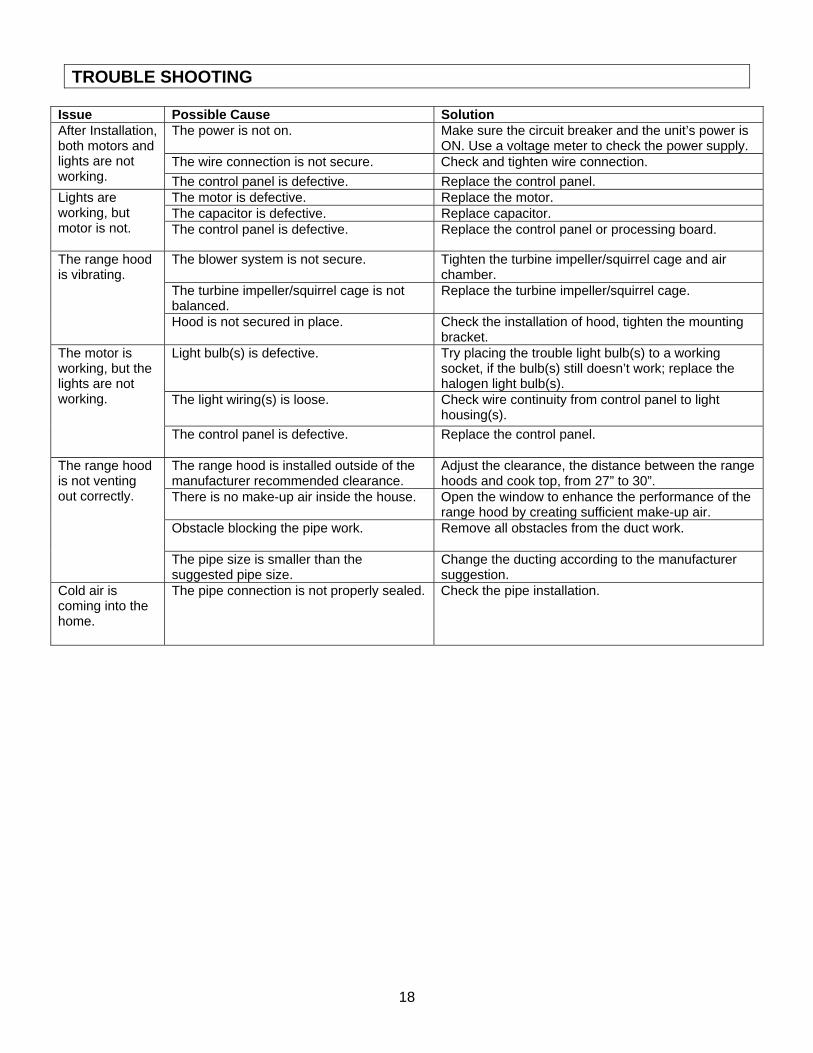
TROUBLE SHOOTING
Issue Possible Cause Solution After Installation, both motors and lights are not working.
The power is not on. Make sure the circuit breaker and the unit’s power is ON. Use a voltage meter to check the power supply.
The wire connection is not secure. Check and tighten wire connection. The control panel is defective. Replace the control panel.
Lights are working, but motor is not.
The motor is defective. Replace the motor. The capacitor is defective. Replace capacitor. The control panel is defective. Replace the control panel or processing board.
The range hood is vibrating.
The blower system is not secure.
Tighten the turbine impeller/squirrel cage and air chamber.
The turbine impeller/squirrel cage is not balanced.
Replace the turbine impeller/squirrel cage.
Hood is not secured in place. Check the installation of hood, tighten the mounting bracket.
The motor is working, but the lights are not working.
Light bulb(s) is defective.
Try placing the trouble light bulb(s) to a working socket, if the bulb(s) still doesn’t work; replace the halogen light bulb(s).
The light wiring(s) is loose.
Check wire continuity from control panel to light housing(s).
The control panel is defective.
Replace the control panel.
The range hood is not venting out correctly.
The range hood is installed outside of the manufacturer recommended clearance.
Adjust the clearance, the distance between the range hoods and cook top, from 27” to 30”.
There is no make-up air inside the house. Open the window to enhance the performance of the range hood by creating sufficient make-up air.
Obstacle blocking the pipe work.
Remove all obstacles from the duct work.
The pipe size is smaller than the suggested pipe size.
Change the ducting according to the manufacturer suggestion.
Cold air is coming into the home.
The pipe connection is not properly sealed. Check the pipe installation.

19
DISCLAIMER 1. CAREFULLY INSPECT ALL ITEMS FOR DAMAGES BEFORE ACCEPTING DELIVERY. NOTE
ANY DAMAGES ON THE FREIGHT BILL OR EXPRESS RECEIPT. REQUEST NAME AND SIGNATURE OF THE CARRIER’S AGENT AND KEEP COPY TO SUPPORT YOUR CLAIM. Upon acceptance of items, owner assumes responsibility for its safe arrival. Report damages to the carrier and file a claim immediately. Failure to do so may result in the denial of your claim. The carrier will furnish you with necessary forms for filing a claim.
DAMAGES CAUSED DURING TRANSIT ARE NOT COVERED UNDER OUR WARRANTY.
2. PLEASE INSPECT CONTENTS OF PACKAGE(S) CAREFULLY UPON RECEIVING! We must be notified in writing of any damages and/or missing parts within the allocated days upon
your receipt of package(s). Contact your local KOBE dealer or distributor or call KOBE for the time limit.
CLAIMS WILL NOT BE ACCEPTED AFTER THE ALLOCATED DAYS. NOTE: ITEMS WERE THOROUGHLY TESTED AND CAREFULLY PACKED IN OUR FACTORY
BEFORE SHIPPING.
3. Products must be returned in good working condition with ALL original parts and documentation packed in ALL original cartons, fillers and shipping cartons. A restocking fee of 25% will be charged for all approved return(s).
EXCHANGES OR RETURNS MAY NOT BE ACCEPTED IF ANY PACKAGING IS MISSING.
4. MAKE SURE TO INSPECT THE HOOD FOR DAMAGES AND DEFECTS BEFORE INSTALLATION. Appearance flaws of the hood found after installation and not affecting hood performance is not covered under our warranty for returns or exchanges. Service visits not covered under warranty will carry a service charge.
A) Before Installation: Return for exchange or refund (please see above for acceptable
returns).
B) After Installation: NO exchange or refund.

20
-WARRANTY
WARRANTY CERTIFICATE
KOBE Range Hoods (referred to herein as “we”or “us”) warrants to the original purchaser (referred to herein as “you” or “your”) all products manufactured or supplied by us to be free from defect in workmanship and materials as follows: TWO-YEAR LIMITED WARRANTY FOR PARTS AND LABOR ON KOBE PREMIUM SERIES: For two years from the date of your original invoice from a KOBE authorized dealer, we will, at our sole discretion, choose to repair or replace the product free of charge that failed due to manufacturing defects. It is your sole responsibility to ensure the product is readily accessible for the service technician to perform repairs. The service technician will not, under any circumstance, remove, alter or modify any fixture built around and/or connected to the product to gain access to perform repairs. During the two-year Limited Warranty period, additional charges may apply which include but are not limited to:
• Service technician travel charges if the requested service location is 30-miles out of KOBE’s authorized service area
• Parts shipping expenses • Un-installation of defective product and Installation of replacement product
EXTENDED BRILLIA WARRANTY (1-YEAR LABOR AND 2-YEAR PARTS) ON KOBE BRILLIA SERIES ONLY. For two year from the date of your original invoice from a KOBE authorized dealer, we will provide free of charge parts and one year labor for Brillia Hoods that failed due to manufacturing defects. It is our sole discretion to choose to repair or replace defective parts.
Warranty Exclusions: This warranty does not cover, including but not limited to the following:
a. Improper installation. b. Any repair, alteration, modification not authorized by KOBE. c. Duct alteration, modification and connection. d. Incorrect electric current, voltage or wiring. e. Normal maintenance and service required for the product. f. Consumable parts such as light bulbs and carbon filters. g. Improper usage of the product that it is not intended for, such as commercial use,
outdoor use and multi-family use. h. Normal wear and tear. i. Chips, scratches or dents by abuse or misuse of the product. j. Damages caused by accident, fire, flood and other Acts of God. k. Expenses incurred for service located outside of the designated service area. l. Purchases from unauthorized dealers. m. Removal fees of defective product and Installation fees associated with replacement
product.

21
If we determine that the warranty exclusions listed above apply or if you fail to provide all necessary documentation for warranty service, you will be responsible for all expenses associated with the requested service, including parts, labor, shipping, travelling and any other expense related to the service request. To qualify for warranty service, you must:
1. Have the ORIGINAL proof of purchase 2. Be the ORIGINAL purchaser of the product 3. Have the model number 4. Have the serial number 5. Have a description of the nature of any defect in the product or part
TO REQUEST WARRANTY SERVICE, PLEASE CONTACT THE KOBE RANGE HOODS SERVICE CENTER: KOBE SERVICE CENTER Tel: 1-855-800-KOBE (5623) E-mail: [email protected]

22
PRODUCT REGISTRATION Register Your Product! Any covered failure occurring within one year of original purchase arising from defective workmanship or material in manufacture will at our discretion, replaced free of charge by KOBE Range Hoods as applicable. Keep proof of purchase (original invoice) handy for inspection. If the range hood is sold by the original purchaser during the warranty period the new owner is protected until expiration of the original purchaser’s warranty. See warranty section for complete warranty coverage information. This appliance has been manufactured, tested, and inspected to the standards required by KOBE Range Hoods. PLEASE MAIL IN YOUR WARRANTY REGISTRATION CARD AND PROOF OF PURCHASE TO: KOBE Range Hoods 11775 Clark Street
Arcadia, CA 91006 U.S.A.
RECORD THE FOLLOWING INFORMATION FOR YOUR RECORD: Model No. ________________________ Serial No. ________________________ Purchased Date _____/_____/_____ Purchased From: ______________________________
______________________________ ______________________________ IMPORTANT: PLEASE KEEP A COPY OF YOUR SALE RECEIPT OR INVOICE HANDY WHEN REQUESTING FOR SERVICE.

KOBE Range Hoods 11775 Clark Street
Arcadia, CA 91006 USA
http://www.KOBERangeHoods.com
This KOBE hood is made for use in the USA and CANADA only. We do not recommend using this hood overseas as the power supply may not be compatible and may violate the electrical code of that country. Using a KOBE hood overseas is at your own risk and will void your warranty.
Information subject to change without notice. VER.120509