Knowledge-Based Graphical Interfaces for Presenting ... Graphical Interfaces for Presenting...
5
Knowledge-Based Graphical Interfaces for Presenting Technical Information Steven Feiner Department of Computer Science Columbia University New York, NY 10027 [email protected] Abstract Designing effective presentations of technical information is extremely difficult and time-consuming. Moreover, the combination of increasing task complexity and declining job skills makes the need for high-quality technical presentations especially urgent. We believe that this need can ultimately be met through the development of knowledge-based graphical interfaces that can design and present technical information. Since much material is most naturally communicated through pictures, our work has stressed the importance of well- designed graphics, concentrating on generating pictures and laying out displays containing them. We describe APEX, a testbed picture generation system that creates sequences of pictures that depict the performance of simple actions in a world of 3D objects. Our system supports rules for determining automatically the objects to be shown in a picture, the style and level of detail with which they should be rendered, the method by which the action itself should be indicated, and the picture’s camera specification. We then describe work on GRIDS, an experimental display layout system that addresses some of the problems in designing displays containing these pictures, determining the position and size of the material to be presented. Keywords: knowledge-based graphics, user interface design, graphical layout, design grids 1. Introduction Technical information design and delivery systems based on paper and microfilm are gradually being replaced by computer-based systems. Conventional approaches to designing the user interfaces to these new systems and the information that they manage typically rely on handcrafted dialogues and parameterized displays. As a consequence, they are expensive and time-consuming to produce, much like the older systems that they replace. One way to improve the interface design process is to use graphical editors, rather than programming, to specify the appearance and interaction capabilities of the user interface. This concept was developed in systems such as [HANA80; FEIN82; WONG82; BUXT83; GREE85; OLSE851 and has since been borrowed and popularized by the recently introduced Hypercard [GOOD87]. 1.1. Editor-Based Design Editor-based systems have shown some dramatic results in allowing users, both programmers and nonprogrammers, to design certain kinds of interfaces in less time than it would take using conventional methods. In addition to increasing design throughput, editor-based systems can also increase design quality by encouraging successive refinement. If some part of the initial design is deemed inadequate it may be relatively easy to modify it. IGD (Interactive Graphical Documents) [FEIN82; FEIN88al is an early example of an experimental editor-based interface design system. Its users create interactive graphical hypermedia presentations that are designed and presented on a high-resolution color monitor. Pictures and typeset text are created with one editor and incorporated into a presentation with another. A display from a sonar maintenance and repair manual created with IGD is shown in Figure 1. This display, as well as the rest of the manual, was designed by a team of authors and illustrators who used the system’s graphical editors, rather than a programming language. The same graphical editor that is used to specify the visual appearance of the display is also used to determine the display’s interactive capabilities. For example, the designer can graphically select objects and make them into buttons that when touched cause actions to be performed, such as jumping to a new display. The editor provides a display of the manual’s structure that allows users to both build and view interconnections between all of the displays. The author’s current work is supported in part by the Defense Advanced Research Projects Agency under Contract NooO39-84-C-0165, the New York State Center for Advanced Technology under Contract NYSSTF- CAT(87)-5, and an equipment grant from the Hewlett-Packard Company. The IGD and APEX systems were supported in part by the Office of Naval Research under Contract NOGO14-78-C-0396 and the National Science Foundation under Grant INT-7302268-A03. 1.2. Problems with Editor-Based Design Our experience, and that of users of commercial systems like Hypercard, have shown that systems of this sort are powerful tools for trying out interface ideas. Unfortunately, there are 253 PRECEDING PAGE BLANK NOT FILMED https://ntrs.nasa.gov/search.jsp?R=19890010480 2018-06-24T09:58:11+00:00Z
Transcript of Knowledge-Based Graphical Interfaces for Presenting ... Graphical Interfaces for Presenting...
Knowledge-Based Graphical Interfaces for Presenting Technical Information
Steven Feiner
Department of Computer Science Columbia University
New York, NY 10027
Abstract
Designing effective presentations of technical information is extremely difficult and time-consuming. Moreover, the combination of increasing task complexity and declining job skills makes the need for high-quality technical presentations especially urgent. We believe that this need can ultimately be met through the development of knowledge-based graphical interfaces that can design and present technical information. Since much material is most naturally communicated through pictures, our work has stressed the importance of well- designed graphics, concentrating on generating pictures and laying out displays containing them.
We describe APEX, a testbed picture generation system that creates sequences of pictures that depict the performance of simple actions in a world of 3D objects. Our system supports rules for determining automatically the objects to be shown in a picture, the style and level of detail with which they should be rendered, the method by which the action itself should be indicated, and the picture’s camera specification. We then describe work on GRIDS, an experimental display layout system that addresses some of the problems in designing displays containing these pictures, determining the position and size of the material to be presented.
Keywords: knowledge-based graphics, user interface design, graphical layout, design grids
1. Introduction
Technical information design and delivery systems based on paper and microfilm are gradually being replaced by computer-based systems. Conventional approaches to designing the user interfaces to these new systems and the information that they manage typically rely on handcrafted dialogues and parameterized displays. As a consequence, they are expensive and time-consuming to produce, much like the older systems that they replace.
One way to improve the interface design process is to use graphical editors, rather than programming, to specify the appearance and interaction capabilities of the user interface. This concept was developed in systems such as [HANA80; FEIN82; WONG82; BUXT83; GREE85; OLSE851 and has since been borrowed and popularized by the recently introduced Hypercard [GOOD87].
1.1. Editor-Based Design
Editor-based systems have shown some dramatic results in allowing users, both programmers and nonprogrammers, to design certain kinds of interfaces in less time than it would take using conventional methods. In addition to increasing design throughput, editor-based systems can also increase design quality by encouraging successive refinement. If some part of the initial design is deemed inadequate it may be relatively easy to modify it.
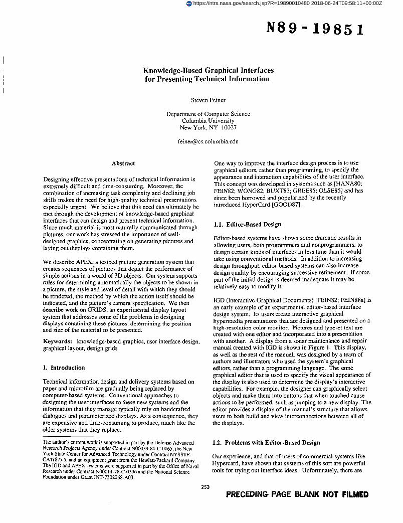
IGD (Interactive Graphical Documents) [FEIN82; FEIN88al is an early example of an experimental editor-based interface design system. Its users create interactive graphical hypermedia presentations that are designed and presented on a high-resolution color monitor. Pictures and typeset text are created with one editor and incorporated into a presentation with another. A display from a sonar maintenance and repair manual created with IGD is shown in Figure 1. This display, as well as the rest of the manual, was designed by a team of authors and illustrators who used the system’s graphical editors, rather than a programming language. The same graphical editor that is used to specify the visual appearance of the display is also used to determine the display’s interactive capabilities. For example, the designer can graphically select objects and make them into buttons that when touched cause actions to be performed, such as jumping to a new display. The editor provides a display of the manual’s structure that allows users to both build and view interconnections between all of the displays.
The author’s current work is supported in part by the Defense Advanced Research Projects Agency under Contract NooO39-84-C-0165, the New York State Center for Advanced Technology under Contract NYSSTF- CAT(87)-5, and an equipment grant from the Hewlett-Packard Company. The IGD and APEX systems were supported in part by the Office of Naval Research under Contract NOGO14-78-C-0396 and the National Science Foundation under Grant INT-7302268-A03.
1.2. Problems with Editor-Based Design
Our experience, and that of users of commercial systems like Hypercard, have shown that systems of this sort are powerful tools for trying out interface ideas. Unfortunately, there are
253 PRECEDING PAGE BLANK NOT FILMED
https://ntrs.nasa.gov/search.jsp?R=19890010480 2018-06-24T09:58:11+00:00Z
ORIGINAL PAGE IS OF POOR QUALITY
b Objecfs User knowledge
and displays includes [ZDYB8 1; FRIE84: MACK86; AREN88; NEAL881.
2. Automating Picture Generation
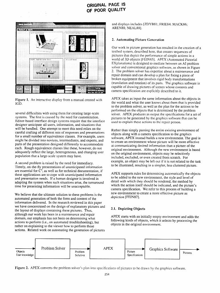
Our work in picture generation has resulted in the creation of a testbed system, described here, that creates sequences of pictures that depict the performance of simple actions in a world of 3D objects [FEIN85]. APEX (Automated Pictorial Explanations) is designed to mediate between an AI problem solver and conventional graphics software, as shown in Figure 2. The problem solver has expertise about a maintenance and repair domain and can develop a plan for fixing a piece of broken equipment that involves rigid body transformations (translation and rotation) of its parts. The graphics software is capable of drawing pictures of scenes whose contents and camera specification are explicitly described to it.
APEX takes as input the same information about the objects in the world and what the user knows about them that is provided to the problem solver, as well as the plan for the actions to be performed on the objects that is determined by the problem solver. APEX produces as output the specifications for a set of pictures to be generated by the graphics software that can be used to explain these actions to the repair person.
~i~~~~ 1. An interactive display from a manual created with IGD.
several difficulties with using them for creating large-scale systems. The first is caused by the need for customization. Editor-based interface design systems require that the interface designer anticipate all users, information, and situations that
Problem Solver b APEX b Graphics Software b Pictures Problem Picture
Solution Specifications
will be handled. One attempt to meet this need relies on the careful crafting of different sets of responses and presentations for a small number of equivalence classes. For example, users might be divided into novices, intermediates, and experts, and parts of the presentation designed differently to accommodate each. Rough equivalence classes like these, however, do not adequately reflect the large, heterogeneous, and changing user population that a large-scale system may have.
Rather than simply passing the entire existing environment of objects along with a camera specification to the graphics software, APEX instead builds a new environment. The goal is to create an environment whose picture will be more effective at communicating desired information than a picture of the original environment. Although the new environment is based on the original environment, objects may be selectively included, excluded, or even created from scratch. For example, an object may be left out if it is not related to the task to be illustrated, resulting in a simpler, less cluttered picture. A second problem is raised by the need for immediacy.
Timely, on-the-fly presentations of unanticipated information are essential for C3, as well as for technicaldocumentation, if
and presentation needs. If a human designer is involved in
time for presenting information will be unacceptable.
We believe that the ultimate solution to these problems is the automated generation of both the form and content of the information delivered. In the research reviewed in this paper we have concentrated on the design of explanatory pictures and the layout of displays containing these pictures. Thus,
these applications are to cope with unanticipated information APEX for determining the objects
adapting the system when such situations arise, the turnaround to be added to the new environment, the style and level of
which the action itself should be indicated, and the picture’s camera specification. We refer to this process of building a new environment to depiction [FEIN87].
with which they be the method by
a more effective picture as
2.1. Depicting Objects
although our work has been in a maintenance and repair domain, our emphasis has not been on determining what actions to perform (Le., on automated troubleshooting), but rather on explaining to the viewer how to perform those
APEX starts with an initially empty environment and adds the following kinds of objects, which it selects by processing the objects in the original environment.
actions. Related work on automating the generation of pictures
Figure 2. APEX converts the problem solver’s plan into specifications of pictures to be drawn by the graphics software.
254
ORIGINAL PAGE IS OF POOR QUALITY
Frame objects. Each of APEX’s pictures is designed to show a particular action being performed. The empty picture crystallizes around a small set of objects that directly participate in the action. We call these the picture’sframe objects since they are specified by the action frame [MINS75] being depicted.
Context objects. Next, APEX adds objects that will provide context for those objects that are already included. The objects in APEX’s world form a hierarchy. Context objects are selected by traveling up the hierarchy starting with each object that was originally included in the picture. Objects encountered are added to the picture up until the first object with which the user is already familiar.
Landmark objects. Although the context objects are helpful, they are often not sufficient to help locate the frame objects and may themselves be difficult to recognize. Therefore, APEX’s picture-making strategy searches for landmark objects that could serve as a reference in locating those objects that have been included in the picture thus far. It does this by examining the objects that are near the important objects and selecting those that have significantly different appearance as determined by their shape, size, or the material from which they are made.
Similar objects. APEX searches the environment for nearby objects that are similar in appearance to those already included. These are added to the picture to help eliminate the chance that the viewer will confuse them with the objects included so far.
Supplementary objects. Additional objects are added in order to assure that the picture looks correct. For example, objects that physically support objects that are already in the picture are added so that the supported objects don’t seem to be floating unsupported.
Meta-objects. In order to show the action being performed in a picture and to help distinguish the objects affected, APEX creates additional objects that are added to the picture. These meru-objecrs are arrows that are used to show translational and rotational motion. At the same time, the position of the arrow also indicates the object being moved.
2.2. Depicting Properties
When APEX adds an object to the picture it also determines several properties: camera specification, rendering style, and level of detail.
Camera specification. The picture’s camera specification is modified for each added object to determine how much of the object should be visible. APEX’s rules force frame objects, context objects, landmarks, similar objects, and meta-objects to be entirely visible. Supplementary objects, on the other hand, either cause no change in the camera specifications or may cause relatively small changes to enable some portion of them to be visible.
Rendering style. APEX selects the rendering style used for each object. Currently only two styles are employed. The
first, the “regular” rendering style, causes objects to be depicted with their actual material properties. This is used for frame objects, context objects, and meta-objects. A “subdued” rendering style is assigned to all other objects that are added to the picture to indicate that they are less important. APEX currently realizes a subdued style by blending the object’s material properties (which determine its rendered color) with the properties of its parent.
Level of detail. APEX determines the level of detail to be used in rendering an object. Only enough detail is used to disambiguate an object from others that are similar in appearance to it. Much work on APEX was devoted to developing a method for determining automatically physical approximations of objects that could be used to depict them at different levels of detail.
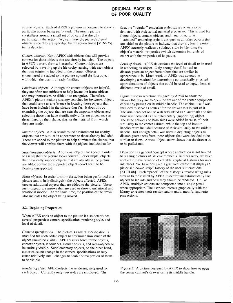
Figure 3 shows a picture designed by APEX to show the viewer that they are to open the drawer of the center equipment cabinet by pulling on its middle handle. The cabinet itself was included to serve as context for the drawer that is part of it. The small cabinet on the wall was added as a landmark and the floor was included as a supplementary (supporting) object. The large cabinets on both sides were added because of their similarity to the center cabinet, while the top and bottom handles were included because of their similarity to the middle handle. Just enough detail was used in depicting objects to disambiguate them from those objects that were decided to be similar to them. A meta-object arrow shows that the drawer is to be pulled out.
Depiction is a general concept whose application is not limited to making pictures of 3D environments. In other work, we have applied it to the creation of editable graphical histones for user interfaces. We have designed a graphical editor that displays a pictorial “comic strip” history of the user’s interactions [KURLSS]. Each “panel” of the history is created using rules similar to those used by APEX to determine automatically the objects to include and how they should be rendered. Unlike APEX, multiple actions are compacted into a single panel when appropriate. The user can interact graphically with the history to review their session and to undo, modify, and redo past actions.
Figure 3. A picture designed by APEX to show how to open the center cabinet’s drawer using its middle handle.
255
In order to create a coherent and effective presentation, not only must pictures (and text) be created, but they must be combined together on the display in a process known as display layout. Our current work in display layout treats some of the problems in determining the position and size of material that is to be presented to the user. We have developed a testbed system called GRIDS (GRaphical Interface Design System), which lays out displays containing pictures and text, determining the size and position of the parts from which they are composed [FEIN88c].
ORIGINAL PAGE IS OF POOR QUAL
1 ead 3. Automating Display Layout
I I I
GRIDS takes as input information about the objects to be displayed, the user, and the display hardware. It uses this to determine a layout that will be applied to each screenful of objects. Its approach is based on the idea of grid-based layout developed by graphic designers [HURL78; MULL811. A design grid, consisting of proportionally-spaced horizontal and vertical lines, is imposed on the space to be laid out. The lines describe a set of rectangular gridjiefds. The fields are separated vertically and horizontally by equal-sized spaces and the array of fields is surrounded on all four sides by margins. Objects are sized and positioned on the grid in such a way that they are aligned with the grid lines. Thus each object is positioned in a part of the grid that is an integral number of fields in height and width.
3.1. Designing a Layout
Our system generates a grid and determines how objects will be placed using it. Its approach is briefly reviewed here and described in more detail in [FEIN88c]. First a grid is created, based on input information about the material to be laid out, the display, and the user. For example, the user's distance from the display constrains the sizes of the fonts and pictures that can be used, while the size and aspect ratio of the physical display constrain both the size and relative position of the objects to be laid out. These in turn help determine the size of the grid's fields, margins, and inter-field spaces.
Next, the grid that the system produces is used in conjunction with input information about the objects to be laid out to generate a prototype display layout. An important part of this input information is a grammar that describes the kinds of objects that will be included in the actual displays. The actual objects that will be presented in a particular display are instances of the general classes of objects that are the grammar's terminals. The system currently supports pictures, body text blocks, and headings. These objects are further specialized by designating limits on their expected size and content. The grammar also specifies grouping relationships among these objects. For example, the grammar may specify that displays can contain pictures that are each related to a block of text that serves as its caption. Finally, the prototype display layout is used to determine how to lay out input instances of the objects described by the display grammar to form the actual displays.
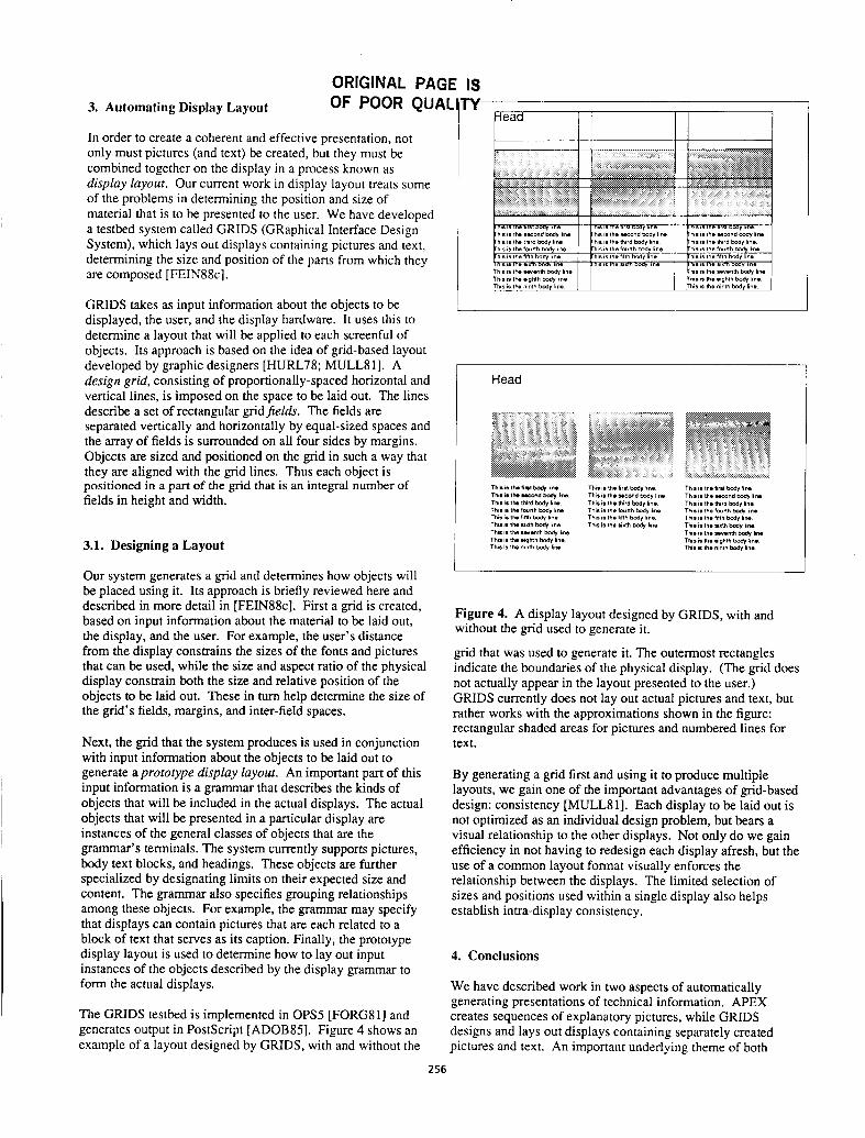
The GRIDS testbed is implemented in OPS5 [FORGgl] and generates output in PostScript [ADOB85]. Figure 4 shows an example of a layout designed by GRIDS, with and without the
I Head
Figure 4. A display layout designed by GRIDS, with and without the grid used to generate it.
grid that was used to generate it. The outermost rectangles indicate the boundaries of the physical display. (The grid does not actually appear in the layout presented to the user.) GRIDS currently does not lay out actual pictures and text, but rather works with the approximations shown in the figure: rectangular shaded areas for pictures and numbered lines for text.
By generating a grid first and using it to produce multiple layouts, we gain one of the important advantages of grid-based design: consistency [MULLgl]. Each display to be laid out is not optimized as an individual design problem, but bears a visual relationship to the other displays. Not only do we gain efficiency in not having to redesign each display afresh, but the use of a common layout format visually enforces the relationship between the displays. The limited selection of sizes and positions used within a single display also helps establish intra-display consistency.
4. Conclusions
We have described work in two aspects of automatically generating presentations of technical information. APEX creates sequences of explanatory pictures, while GRIDS designs and lays out displays containing separately created pictures and text. An important underlying theme of both
256
systems is that to ensure a consistent presentation, a common set of design rules should be provided or generated first, and then used to create individual pictures and displays.
The projects described here are partial, testbed implementations of a general conceptual architecture for generating both layout and information content automatically [FEIN88b]. Much work remains to be done to eventually develop robust, knowledge-based design systems that can produce timely, high-quality technical presentations that are customized to the needs of particular users.
References
[ADOB85]
[AREN88]
[BUXT83]
[FEIN82]
[FEIN85]
[FEIN87]
[ FE I N8 8 a]
[FEIN88b]
[FEIN88c]
[ FORGX I I
Adobe Systems Inc. PostScript Language Reference Manual. MA: Addison-Wesley, 1985. Arens, Y., Miller, L., and Sondheimer, N. “Presentation Planning Using an Integrated Knowledge Base.” Proc. ACMISIGCHI Workshop on Architectures for Intelligent Interfaces: Elements and Prototypes, Monterey, CA, Mar 29-Apr 1, 1988,93-107.
Buxton, B. “Toward a Comprehensive User Interface Management System.” Computer Graphics, 17:3, July 1983,35-42. Feiner, S., Nagy, S., and van Dam, A. “An Experimental System for Creating and Presenting Interactive Graphical Documents.” ACM Trans. on Graphics, 1:l January 1982, 59-77. Feiner, S. “APEX: An Experiment in the Automated Creation of Pictorial Explanations.” IEEE Computer Graphics and Applications, 5:11, November 1985,29-38. Feiner, S. A framework for automated picture generation. Columbia Univ. Dept. of Comp. Sci. Tech. Rep. CUCS-277-87, 1987.
Feiner, S. “Seeing the Forest for the Trees: Hierarchical Display of Hypertext Structure.” Proc. COIS88 (ACM-SICOISIIEEE Comp. Soc. Conf. on Offrce Info. Sys.), Palo Alto, March 23-25, 1988, 205-212. Feiner, S. “An Architecture for Knowledge- Based Graphical Interfaces.” Proc. ACMISIGCHI Workshop on Architectures for Intelligent Interfaces: Elements and Prototypes, Monterey, CA, Mar 29-Apr 1,
Feiner, S. “A Grid-Based Approach to Automating Display Layout.” Proc. Graphics Interfuce ’88, Edmonton, June 6-10, 1988 (Morgan Kaufmann, Palo Alto, 1988), 192- 197. Forgy, C. OPSS User’s Manual. Computer Science Technical Report CMU-CS-81-135, Carnegie-Mellon University, July 1981.
1988, 129-140.
[FRIE84]
[GOOD871
[CREE851
[HANA80]
[ HURL7 81
[KURL88]
[MACK861
[MINS75]
[MULL811
[NEAL881
[OLSE85]
[WONG82]
[ZDYBgl]
Friedell, M. “Automatic Synthesis of Graphical Object Descriptions.” Computer Graphics, 18:3, July 1984, 53-62. Goodman, D. The Complete Hypercard Handbook, NY: Bantam Books, 1987. Green, M. “The University of Alberta User Interface Management System.” Computer Graphics, 19:3, July 1985,205-213. Hanau, P. and Lenorovitz, D. “Prototyping and Simulation Tools for User/Computer Dialogue Design.” Computer Graphics, 14:3,
Hurlburt, A. The Grid. NY: Van Nostrand Reinhold Co., 1978. Kurlander, D. and Feiner, S. “Editable Graphical Histories.” To appear in Proc. I988 IEEE Comp. SOC. Workshop on Visual Languages, October 10-12, 1988, Pittsburgh, PA. Mackinlay, J. “Automating the Design of Graphical Presentations of Relational Information.” ACM Trans. on Graphics, 5:2,
Minsky, M. “A Framework for Representing Knowledge.” In P. Winston (ed.), The Psychology of Computer Vision, McGraw-Hill,
Muller-Brockmann, J. Grid Systems in Graphic Design. Niederteufen, Switzerland: Verlag Arthur Niggli, 198 1. Neal, J. and Shapiro, S. “Intelligent Multi- Media Interface Technology.” Proc. ACMISIGCHI Workshop on Architectures for Intelligent Interfaces: Elements and Prototypes, Monterey, CA, Mar 29-Apr 1,
Olsen Jr., D., Dempsey, E., and Rogge, R. “Input/Output Linkage in a User Interface Management System.” Computer Graphics,
Wong, P., and Reid, E. “FLAIR - User Interface Dialog Design Tool.” Computer Graphics, 16:3, July 1982, 87-98. Zdybel, F., Greenfeld, N., Yonke, M., and Gibbons, J. “An Information Presentation System.” Proc. IJCAI 8I , Vancouver, August
July 1980,271-278.
April 1986, 110-141.
1975,211-277.
1988,69-91.
19~3, July 1983, 191-197.
24-28, 1981,978-984.
257