
Knowledge based and heuristic approach …...Knowledge based and heuristic approach to the cost...
12
Knowledge based and heuristic approach to the cost optimum design of concrete structures R.R. Reddy", A. Gupta\ R.R Singh^ Department of Civil Engineering, Osmania University, Hyderabad-500007, India ^Department of Civil Engineering, Indian Institute of Technology, Delhi-110016, India ABSTRACT An expert system has been developed for optimum design of reinforced concrete members, called EXFORM. Optimization at the conceptual design phase has so far been based on informal methods i.e the knowledge of the designer gained through past experience. In this paper a formal method has been proposed forcost optimization of reinforced concrete structures. An appropriate cost function has been derived to estimate optimum percentage of steel. EXFORM makes use ofthis cost function along with heuristic knowledge of the designer. INTRODUCTION The design process of any structure involves (i) conceptual design and (ii) design realization. Conceptual design is largely done in mind, characterized by a high degree of ambiguity, with possibility of more than one acceptable solution. A majority of the decisions are taken during the conceptual de- sign. Therefore, any optimization at the conceptual design phase will realize greater savings than at a later design stage, where decisions become more restricted. The decisions made during conceptual design have been based on informal optimization methods. The designer uses his expertise, which is often heuristic, to find optimum solutions. Lane (1985) suggested thatit would be advantageous 1) to introduce more formal methods and if possible computer-based methods within conceptual design, 2) to capture designer's knowledge which is used to select optimum designs and to use this cap- tured knowledge as knowledge base forformal methods of (1) above. Gero, Nowacki, Amkreutz, Spillers, Mistree, Radfor and others discussing with Lane (1985) have also concurred with the above concept. The optimization has been usually achieved by making use of mathematical and numerical search methods at the design realization stage. However, the objective of such struc- Transactions on the Built Environment vol 2, © 1993 WIT Press, www.witpress.com, ISSN 1743-3509
Transcript of Knowledge based and heuristic approach …...Knowledge based and heuristic approach to the cost...

Knowledge based and heuristic approach
to the cost optimum design of concrete
structures
R.R. Reddy", A. Gupta\ R.R Singh^
Department of Civil Engineering, Osmania
University, Hyderabad-500007, India
^Department of Civil Engineering, Indian Institute
of Technology, Delhi-110016, India
ABSTRACT
An expert system has been developed for optimum design of reinforcedconcrete members, called EXFORM. Optimization at the conceptual designphase has so far been based on informal methods i.e the knowledge of thedesigner gained through past experience. In this paper a formal methodhas been proposed for cost optimization of reinforced concrete structures. Anappropriate cost function has been derived to estimate optimum percentage ofsteel. EXFORM makes use of this cost function along with heuristic knowledge
of the designer.
INTRODUCTION
The design process of any structure involves (i) conceptual design and (ii)design realization. Conceptual design is largely done in mind, characterizedby a high degree of ambiguity, with possibility of more than one acceptablesolution. A majority of the decisions are taken during the conceptual de-sign. Therefore, any optimization at the conceptual design phase will realizegreater savings than at a later design stage, where decisions become morerestricted. The decisions made during conceptual design have been basedon informal optimization methods. The designer uses his expertise, whichis often heuristic, to find optimum solutions. Lane (1985) suggested that itwould be advantageous 1) to introduce more formal methods and if possiblecomputer-based methods within conceptual design, 2) to capture designer'sknowledge which is used to select optimum designs and to use this cap-tured knowledge as knowledge base for formal methods of (1) above. Gero,Nowacki, Amkreutz, Spillers, Mistree, Radfor and others discussing with Lane(1985) have also concurred with the above concept. The optimization hasbeen usually achieved by making use of mathematical and numerical searchmethods at the design realization stage. However, the objective of such struc-
Transactions on the Built Environment vol 2, © 1993 WIT Press, www.witpress.com, ISSN 1743-3509

224 Optimization of Structural Systems
tural optimization was weight minimization. Adeli & Balasubramanyam (1988)have developed BTEXPERT, an expert system for the optimum design of steelstructures, using minimum weight approach, which is realistic in structuresusing homogenous materials such as steel. Same may not be said aboutcomposite materials like reinforced concrete (RC) structures, where steel andconcrete are involved. However, an attempt has been made in economicalsizing of RC structures. Billig (1960), Gray (1964), Raynolds (1971), Saxenaet al.(1985) have attempted optimization techniques on reinforced concretestructures, but like many others, their effort was also directed towards weightminimization. In the above studies it was assumed that the structure usingminimum weight of concrete will be the minimum cost structure. But becauseof different prices of concrete, steel, formwork and work force, it may notalways be true. Further, many designers in practice concur that the mosteconomical design of reinforced concrete structures is achieved by combiningthe use of steel and concrete in proportion to their respective cost. Thus thereis a need to develop a cost function, preferably at conceptual design stage,which leads to the optimum use of steel and concrete and also minimizes theuse of formwork and workforce.
In this paper, the authors have developed an expert system EXFORM for thecost optimum design of reinforced concrete members at the conceptual designphase. The whole process is divided into two stages. In the first stage anappropriate cost function is derived. For the derived function, an algorithmis generated. In the second stage, the algorithm for the cost function anddesign modules are coupled with knowledge base comprising rules, facts andmetafacts in developing the expert system. The expert system developed is apart of theentire process of design optimization in reinforced concrete structures.The scope of the work is extended to the design of circular, square andrectangular shapes for columns; T,L and rectangular shaped beams, alongwith the design of both one way and two way slabs.
COST FUNCTION
The cost function is a function that is to be minimized and is a scalar functioncapable of finding numerical value, for design specification of design variables.Identification of the cost function requires designers experience, insight andknowledge about variables. The cost function enables to determine the per-centage of steel with respect to overall gross cross section area of the membersin reinforced concrete structures. In the cost function forces, mix-proportion,allowable stresses and densities of steel and concrete are treated as designvariables whose values are to be supplied by the designer. In order to minimizethe cost of reinforced concrete member, the cost function includes the costof construction per unit length of reinforced concrete member which includescost of materials, formwork and workforce. The cost of steel and concrete perunit weight, required in the cost function, is available from suppliers. From
Transactions on the Built Environment vol 2, © 1993 WIT Press, www.witpress.com, ISSN 1743-3509

Optimization of Structural Systems 225
field practice, steel fabrication cost is evaluated on the basis of steel tonnage.Thus, it is possible to include the cost of steel fabrication along with the costof steel in terms of weight. On same lines cost of concrete includes the cost offormwork and its workforce. This is justifiable because, the cost of formwork isproportional to the concrete surface area and the cost of workforce is related tothe concrete quantity. From the above discussion, it can be safely presumedthat, the cost of structure is the sum of the cost of steel and concrete, whilesteel and concrete cost includes cost of formwork and workforce.
Mathematical modelling
The cost function has been derived with the following assumptions:
1) the structure is subjected to axial and/or fiexural forces,
2) total load is shared by steel and concrete alone,
3) members are designed as balanced section,
4) cost of concrete and steel govern the cost of structural member,
5) the design is based on both working stress and ultimate strength methods.
In addition to the above assumptions use is made of well known formula forthe design of compression members shown below.
+ AC.C < P 0)
Which is relevant to the assumptions 1 ,2 and 5. Where AS and <rsy are area andallowable stress in steel, A, and C are area and allowable stress in concrete, Pis the total compressive load acting axially on the column. Secondly, in orderto incorporate cost factors for steel and concrete corresponding to assumptions2 and 4, the following function has been used.
s + < X (2)
where RS, <$s, Re, &c are the cost and densities of both steel and concreterespectively. X is the total approximate cost per unit length of the member underconsideration. The value of X is estimated from heuristics and design theories.The details of the same are available elsewhere in the paper. Considering theupper limits of equation (1) and (2) an expression for concrete area AC is arrived
at in terms of X, P, AS, RS> <?sy, <%s, <5c, Re and C.
Ac = [(X-P)- As(£s.Rs- <fsy)]/(6c.Rc- Q ®
On further substituting Ac in equation (1) an expression for As is derived as
AS = (Sc.P. RC-X.C)/(*C.RC- o-sy-6s.Rs.C) ^
Using AS value obtained from expression (4) and substituting in equation (1),concrete area AC can be worked out. On observing expression (4), except
Transactions on the Built Environment vol 2, © 1993 WIT Press, www.witpress.com, ISSN 1743-3509

226 Optimization ot~ Structural Systems
cost of the member, all other parameters are known beforehand. The onl^constraint in this situation being,
AS / AC < 0.035 (5
On similar lines for a column subjected to an eccentric loading, load P irexpression (4) is replaced by P(1 + e) and a new constraint function is use<in addition to expression (5), i.e,
P (C.d q G.e.fc) / b.d̂ < 1.0 (6
where 'd' is the depth and 'b' is the width of the member under consideration'e' is the eccentricity of load, fc is the allowable bending stress in concrete.
For the design of flexural members a different cost function is derived. Irderiving use is made of the fact that the total moment and cost is sharecby concrete and steel. In addition to expression (2), the following additionsexpression is used.
MI + M2 = M (7
Where M1 and M2 are moment carrying capacity of concrete and steel respectively. Using expressions (2) and (7) a new quadratic expression is generatecas shown below.
K-j.d^ + K2.d + Kg = 0 (8
KI = Q.b.Rs.̂ s + j.b.Rc.̂ c (9
f<2 = t.j.X (10
d = [-K2±{(K.4.Ki.Kg)]/2.Ki (12
d > L / 25 (13)
Expression (12) is the solution for expression (8), and expression (13) is th<constraint function which satisfies shear and direction criteria. In the abov<expressions j, Q are shape and mix parameter known before hand. L is th<span of flexural members. The solution obtained is the cost optimum depthrequires to be matched with the nearest practically applicable size from th<knowledge base.
ARCHITECTURE OF EXFORM
In order to automate the above described complex process of the detailecoptimum design of reinforced concrete members, a coupled expert systemhas been developed, called EXFORM i.e, expert system for optimum desigiof reinforced concrete members. The Expert System uses symbolic logii
Transactions on the Built Environment vol 2, © 1993 WIT Press, www.witpress.com, ISSN 1743-3509

Optimization ot" Structural Systems 227
manipulation. The symbols are of floating nature and can be made to interactat any computational situation. For development of expert system, an expertsystem environment M1 (1986) has been used. M1 has capabilities of 1000 +rules. It has add-on editorial facility, infering capability and required explanationfacility. Further it has built-in integrating capability through "savecache" and"loadcache" commands via cache facility. It has both forward chaining andbackward chaining facility. Nocache facility available with the environment,helps in preventing unwanted memory occupation.
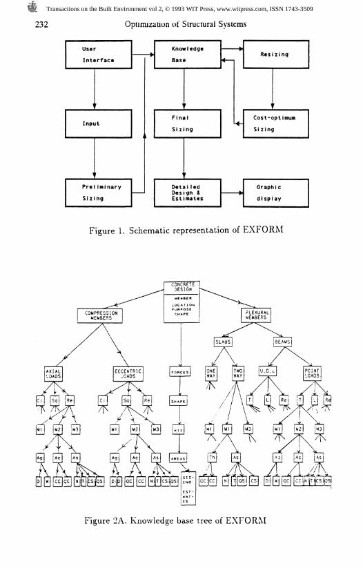
A schematic representation of EXFORM is shown in Fig.1. In Fig.1, a) userinterface is the medium to capture minimum requirements for activating designprocess, b) preliminary sizes arrived with the help of design modules and userresponses, c) knowledge base helps to choose nearest practical sizes, d)resizing activates design modules, calculates area and approximate cost forpossible practical sizes, e) area and cost along with user response plus costfunction realizes optimum sizes, f) knowledge base validates optimum sizesarrived at, g) above results help in realisable design, estimates quantity andcost. The knowledge base component of EXFORM is discussed below.
Knowledge Base
The knowledge base in EXFORM is modelled to design reinforced concretemembers with special emphasis on building design. Design goals are achievedin two steps. In the first step minimum inputs required for the design are sup-plied. In the second step all the inputs are encoded symbolically and activatedwith design modules, cost function and knowledge base for successful manip-ulation. Goals and sub-goals are achieved by operators to reach final designgoals. The entire knowledge base comprises of user interface, rules, designmodules, cost functions and graphic displays.
User interface is a media through which user needs are fed into expert systems.Responses are encoded and captured in symbolical form.
In EXFORM also user needs are supplied through common user interface i.ekey board provided with computer. Some common user input for concretedesign situation are the purpose of the structure, slab area influencing loads,proposed mix design, desired shape for the structural members, allowablestresses of materials, available steel diameter and cost of materials to beused.
Rules are a way of representing knowledge base components, comprisingsmall chunks of information or knowledge encoded in symbolic form. Theserules capture heuristic knowledge, design theories and search techniques inclause form. Number of rules together constitute a set. Each set representsa design situation with predetermined goal or subgoal. These rules are actedupon by operators to reach the desired goal or subgoal. In EXFORM entire
Transactions on the Built Environment vol 2, © 1993 WIT Press, www.witpress.com, ISSN 1743-3509
228 Optimization of Structural Systems
knowledge, heuristics, design modules and cost functions are represented inthe form of rules.
Design modules (DM) in EXFORM are well established equations used inarriving at goals. DMs help feeding new information, evaluating user needs,checking constraints and calculating sizes, areas, quantity and cost of materialsin use.
Cost functions on the other hand are the core of EXFORM. They are used inassociation with DMs, knowledge base and helps in designing cost optimumconcrete members.
Graphics and display is a visual media which enhances understanding andquality of work. EXFORM uses static graphic display with variable design data.Variable design data in symbolic form is a set of captured design goals orsubgoals.
Knowledge Representation
The knowledge representation of EXFORM is composed of a set of productionrules, facts and meta-facts. A production rule is of the form: 'If this conditionholds then this action is appropriate'. The IF part of the production rule statesthe condition that must be present for the production to be applicable andthe THEN part, consisting of certainty factors, is the appropriate action to betaken. Sample rules in EXFORM are represented as,
kb-1: if concrete-mix = mfifteen cf 80
then concrete-allowable-stress = 40.
Where 'cf is certainty factor to tackle uncertainty. Meta-fact is a knowledgebase entry that provides information or directions about how to determine avalue rather than directly equate an expression to a value and is a method foruser response interface. The responses of the user are encoded in a symbolicform and help in processing through knowledge base interaction. These metafacts in EXFORM are of the form
mf-1: question(purpose) = ['Is the column an integral part of residential, com-mercial, public or industrial building?'].
legalvals(purpose) = [residential, commercial, public, industrial].
In the above format a symbol 'purpose' occupies the place of expression, andis assigned for the entire text shown on the right hand side. The user responseto the question is one of the values on the right hand side of legal-values. Thisresponse in symbolic form is matched with its corresponding design modulesand rules in the knowledge base and is activated. The fact on the other handis of the form,
Transactions on the Built Environment vol 2, © 1993 WIT Press, www.witpress.com, ISSN 1743-3509

Optimization of Structural Systems 229
kb-41: cioad = 70 cf 100.
The knowledge base rules, facts, design modules and meta facts are clubbedto form a set. Different sets are generated for different design situations.Each set is a complete design philosophy of the member under consideration.With the user responses, relevant set is activated through symbols. In thedevelopment of the knowledge base set, except for the recommendation rules,every conclusion made by a rule is used as input to the succeeding rule.
KNOWLEGE BASE DEVELOPMENT
In EXFORM the knowledge base generated is a combination of establishedscientific theories, heuristics, cost function, and codal constraints. The entireknowledge base is divided into two design segments as shown in Fig.2. Firstsegment deals with the column members. Second segment deals with thedesign of flexural members i.e beams and slabs.
The column knowledge base is split into two design sets. One for purely axialload situation and another for loads acting eccentrically. Each of these setshave access to the same cost function independently. The knowledge baseis common for both situations. It comprises facts, rules and meta-facts.For different user responses, relevant set of design modules and knowledgebase is activated. The knowledge base constitutes twenty-four permutationsfor each of rectangular, circular and square shapes. Design solutions arearrived at after user selecting appropriate choice from three mix-proportion,steel grade, eight steel diameter, rod numbers satisfying formwork constraintsand tie rod diameters with three options of spacing.
For the design of beams, sets are generated for the design of simply supportedand fixed end situation. In the development of the system, two types of loadsi.e. point and distributed have been considered. The choice of three mixproportion, steel grade and eight steel diameters have been incorporated. Theallowable stress capability is as per Indian standard code and is captured infact base. Analytical modules are incorporated for evaluating member forces,sizes, spacing and rod numbers. While sizing, width of the members havebeen limited to three situations based on architectural constraints i.e, width isequal to wall thickness or user response. Depth on the other hand extendedto ten variations each of T, L, and rectangular shapes. The necessary rods atcentre top and support have been included in association with design modules.Slab knowledge base deals with spans spanning in one and two directions,edges being simply supported or fixed. The user response to the purpose ofbuilding i.e.residential, commercial, industrial or public activates the rules anddesign modules. Live loads for different situations are fed from fact base. Deadloads evaluated by design modules and live loads, fed from fact base, forvarying purpose, help in determining member forces. These member forcesand slab span are used in evaluating design parameters i.e, thickness, steel
Transactions on the Built Environment vol 2, © 1993 WIT Press, www.witpress.com, ISSN 1743-3509
230 Optimization of Structural Systems
area, diameter and spacing. The results of each of the above parameters arecompared with knowledge base and final practical values are adopted.
Expert system for reinforced concrete members developed here is activated byuser responses. These user responses are transformed into symbolic form forconvenience of computation. These symbols help in finding forces in variousstructural members with the help of numerically coupled rule base. Approxi-mate sizing of the members is established, cost of the member designed isarrived at. At this stage already available user response in the memory i.e, costand properties of various materials in use and codal provisions are made tointeract with calculated forces. Derived expression for cost optimum designsis activated to arrive at an exact cost optimum percentage steel in reinforcedconcrete member. Near exact theoretical sizing is fixed. Knowledge base helpsin arriving at practical size, which can be the same as theortical size or it canbe nearest higher size. This new acquired size is the actual practical size forconstruction. The new load carrying capacity of steel is calculated. The actualsteel area is arrived. Available diameter enables to find likely number of steelrods to be used. The quantities and cost of various materials are estimated.These results are displayed graphically and archieved for further processing ofthe design and is ready to interact with next order of expert system. Although,it is well known that any expert system at a given point of time can only beconsidered as prototype model. The expert system developed here for thesizing and designing of reinforced concrete members with cost optimizationis a part of working model of large design process.
The sizes of reinforced concrete structural components are based on infor-mation from the user in the form of span, mix-proportion, loads, location,shape desired if any and bearing capacity, etc. The expert system calculatesthe necessary design requirements from the user input, cost function, designmodules and scans the knowledge base to arrive at the nearest practicallyadoptable size for different structural components. Integrating design detailsof various structural members is the solution of overall design problem. Asample consultation session of EXFORM is in Appendix-1.
SUMMARY AND CONCLUSIONS
In the present work, the use of knowledge based expert system in the opti-mization of structural design of reinforced concrete members is successfullydemonstrated. The use of an algorithm generated for the derived cost functionand incorporated in the development of knowledge base is found to be ofpractical use. It helps in identifying the most cost optimum size for structuralcomponents at conceptual design stage. The use of the above cost functionin designing reinforced concrete members results into more realistic propor-tioning of steel and concrete. This leads to a cost effective balanced section.Thus it can be concluded that the cost function helps not only as a startingpoint in design but in optimizing the reinforced concrete members with fewertrials. The EXFORM expert system helps and eases uncertainties in the design
Transactions on the Built Environment vol 2, © 1993 WIT Press, www.witpress.com, ISSN 1743-3509

Optimization of Structural Systems 231
optimization. The use of production rules in representing engineering designand knowledge is found to be effective. Graphic display although adequaterequires to be more dynamic. In developing the knowledge base the use ofdomain independent shell M1 is satisfactory.
REFERENCES
Adeli, H. and Balasubramanyam, K.V.,(1988)," A coupled expert system foroptimum design of bridges", IEEE- proceedings, 114-119.
Billig, K.L, (1960), " Structural concrete", Macmillan, London.
Gray, W.S., (1964), " Reinforced Concrete water towers,silos and gantries",Concrete publications, London.
Lane, V.P.and Laucopoulas, P., (1985) "Knowledge based system as mechanisefor optimization of conceptual design in civil engineering projects", Elsevierscience publication, 81-107.
M1, (1986), " Reference manual", Teknowledge Inc., U.S.A.
Raynolds, C.E., (1971), "Reinforced concrete designers hand book", Concretepublications, London.
Reddy, R.R, Gupta, Ashok and Singh,R.P., (1991), "Expert system for optimumdesign of concrete members", ASCE Journal, Computing in Civil Engineering,accepted for publication- April 1993 issue.
Saxena, M., Sharma, S.P. and Mohan, C., (1985), "Use of non linear opti-mization technique in determining the optimal design of Intze tanks on shafts",Int.J. Engineering optimization.
Chandra, R., (1985), "Design of concrete members with ribbed-torsteel",Torsteel research foundation in India, Culcutta.
Transactions on the Built Environment vol 2, © 1993 WIT Press, www.witpress.com, ISSN 1743-3509
232 Optimization of Structural Systems
UserInterface
i
Inpi
\
jt
r
Prel iminarySizing
k.
t
KnowledgeBase
i
Fin;Siz
ilng
Detai ledDesign &Estimates
4-
k.
Resizing
\ '
Cost-optimumSizing
Graphicdi splay
Figure 1. Schematic representation of EXFORM
CONCRETEDESIGNMEMBER
'.OCAT IONPURPOSESHAPE
Figure 2A. Knowledge base tree of EXFORM
Transactions on the Built Environment vol 2, © 1993 WIT Press, www.witpress.com, ISSN 1743-3509
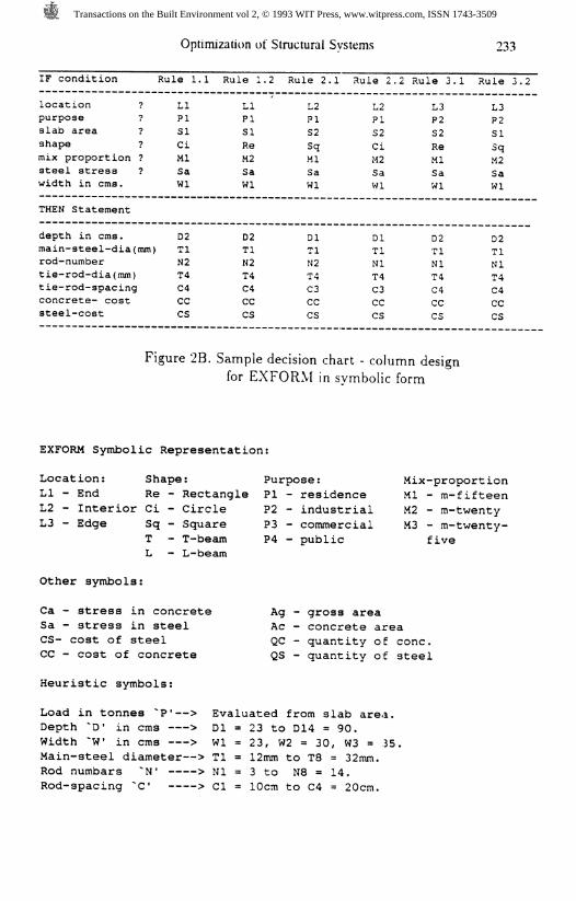
IF condition
location ?purpose ?slab area ?shape ?mix proportion ?steel stress ?width in cms.
THEN Statement
depth in cms.main-steel-dia(mm)rod-numbertie-rod-dia(mm)tie-rod-spacingconcrete- coststeel-cost
Optim
Rule 1.1
LIPISICiMlSaWl
D2TlN2T4C4CCCS
ization of
Rule 1.
LIPISIReM2SaWl
02TlN2T4C4CCCS
Structural
2 Rule 2
L2PIS2SqMlSaWl
DlTlN2T4C3CCCS
Systems
.1 Rule 2,
L2PIS2CiM2SaWl
DlTlNlT4C3CCCS
.2 Rule 3.1
L3P2S2ReMlSaWl
D2TlNlT4C4CCCS
233
Rule 3.2
L3P2SISqM2SaWl
02TlNlT4C4CCCS
Figure 2B. Sample decision chart - column designfor EXFORM in symbolic form
EXFORM Symbolic Representation:
Location: Shape: Purpose:LI - End Re - Rectangle PI - residenceL2 - Interior Ci - Circle P2 - industrialL3 - Edge Sq - Square P3 - commercial
T - T-beam P4 - publicL - L-beam
Mix-proportionMl - m-fifteenM2 - m-twentyM3 - m-twenty-
five
Other symbols:
Ca - stress in concreteSa - stress in steelCS- cost of steelCC - cost of concrete
Heuristic symbols:
Ag - gross areaAc - concrete areaQC - quantity of cone.QS - quantity of steel
Load in tonnes ~P'—> Evaluated from slab area.Depth ~D' in cms > Dl = 23 to D14 = 90.Width ~W in cms > Wl = 23, W2 = 30, W3 = 35.Main-steel diameter—> Tl = 12mm to T8 = 32mm.Rod numbars ~N' > Nl = 3 to N8 = 14.Rod-spacing ~C' > CI = 10cm to C4 = 20cm.
Transactions on the Built Environment vol 2, © 1993 WIT Press, www.witpress.com, ISSN 1743-3509

234 Optimization of Structural Systems
APPENDIX-I
M.l> go.Execution. No knowledge base is present.create one with "add".(Error 220)
Please load or
M.l> load expert.M.l> 90.What is the approximate area of floor slab influencing
the load on the column in sq. feet?» 500.How many stories uo you intend to build?» 2.Is the column an integral part of residential,
commercial , public or industrial building?» residential.What shape do you desire for the column?» rectangular.Execution. "rectangular" is not a legal response.(Error 218)Your response must be chosen from the following:circle, square, rectangle.What shape do you desire for tne column?» rectangle.What mix proportion do you intend to use in the
design of column?» mtwenty.What is the allowable stress in steel in kg per
square cm?» 1750.Execution. "1750" is not a legal response.(Error 218)Your response must be a real number.Whan is the allowable stress in steel in kg per
square cm?» 1750.0.What is the width desired for rectangular column?» 30.What is the cost of concrete per kilogram?» 1.0.What is the cost of steel per kilogram?» 12.0.Choose any one of the steel diametre in mm from below?» 20.The member designed is a short rectangular column withshorter dimension of 30 cm, and longer dimension 35 cm.Steel diameter chosen is 20mm and numbering 6with halfthe number placed near the shorter edges in rows. Minimumcover on all sides is 2.5 cm. Stirrup spacing of 10cm c/cof diametre 8mm. Mix proposed is mtwenty.
----------o o
20mm dia6
numbero o
<-1
20mm
.cf 90
< 30 >
column sectionmtwenty
8mm lOc/cdia, 6 number
column elevationtocostl = 2031.12 (100%) because kb-89.
Transactions on the Built Environment vol 2, © 1993 WIT Press, www.witpress.com, ISSN 1743-3509


![Informed [Heuristic] Search - University of Delawaredecker/courses/681s07/pdfs/04-Heuristic...Informed [Heuristic] Search Heuristic: “A rule of thumb, simplification, or educated](https://static.fdocuments.net/doc/165x107/5aa1e13c7f8b9a84398c48b6/informed-heuristic-search-university-of-delaware-deckercourses681s07pdfs04-heuristicinformed.jpg)
