
KNE High-Pressure Boiler Feed Pumps - · PDF fileHIGH-PRESSURE BOILER FEED PUMPS KNE PUMP...
10
KNE High-Pressure Boiler Feed Pumps
Transcript of KNE High-Pressure Boiler Feed Pumps - · PDF fileHIGH-PRESSURE BOILER FEED PUMPS KNE PUMP...

KNEHigh-Pressure Boiler Feed Pumps

2
HIGH-PRESSURE BOILERFEED PUMPS KNE
PUMP APPLICATION
KNE pumps are intended for power generating units of 200 MW and 660 MW outputs.
PUMP TYPE DESIGNATION
DESCRIPTION
Boiler feed water pumps KNE are designed as multistage, centrifugal, horizontal, barrel-type.
Pump can be dismantled into two sub-units:• High pressure pump barrel• Internal pump stator (complete pumping unit)
This arrangement offers to the pump user a prompt pump repair by replacing of the pump’s internal stator.
High-pressure pump barrel body is made of alloyed steel of high rigidity. Sealing and centring surfaces are furnished by weld deposits of austenitic stainless steel. Suction and discharge branches welded to the barrel body are of the same material. Branches of the high-pressure barrel can be flanged or of a “weld-in” execution. In case of the “weld-in” version the pump barrel is firmly welded into the piping system and contingent repairs are executed by replacement of the pump internal stator, fixed to the pump barrel by hydraulically stretched screws.
The internal pump stator itself consists of the pump rotor, internal stator part, balance device, mechanical seals, radial slide bearings and an axial bearing. Internal stator is assembled, checked and tested by the producer in such a way to be possibly built into any high- pressure pump barrel of the same pump size.
BALANCE DEVICE BEARINGS
KNE-4.1 Balance disc, Counter balance disc
Radial bearings + subsidiary additional one-legged axial bearing are lubricated by pressurised oil
KNE-5.1 Balance drum, Balance drum bush
Radial bearings and two-sided axial bearing are lubricated by pressurised oil
Type KNE
Design size 5.1
Discharge branch diameter 300
Number of stages 6
Design version 000
Balance device “balance disc - counter balance disc”
Balance device “balance drum - balance drum bush”

3
BASIC INFORMATION
Pumped liquid Feedwater
Pump Flow Q max. 320 l/s
Delivery head H max. 5000 m
Operationaltemperature t max. 200 °C
Pump speed n max. 5100 1/min
Position Part designation Material
108 Stage body GX4CrNi13-4 1.4317 + QT2
130 Suction body GX4CrNi13-4 1.4317 + QT2
151 Pump barrel 23CrNiMo747V 1.6749.95
160.1 Barrel cover 23CrNiMo747V 1.6749.95
160.2 Cover – suction side S235J2G3 1.0116
170 Diffuser GX4CrNi13-4 1.4317 + QT2
210 Shaft X3CrNiMo13-4 1.4313+QT900
230.1 Impeller GX4CrNi13-4 1.4317 + QT2
441 Mechanical seal body GX4CrNi13-4 1.4317 + QT2
502 Wear ring X120Cr19Mo3 3346.9
603 Balance drum X120Cr19Mo3 3347.9
605 Balance drum bush X120Cr16Mo2 3346.9
905 Cover screw 30CrNiMo8 1.6580+QT
920 Nut 34CrNiMo6 1.6582+QT
MECHANICAL SEAL
Pumps are equipped by single mechanical seals with cooling chambers installed in accordance with API plan 23.
PUMPING SET ARRANGEMENT
Pump is supplied on a separate base plate. Pump can be driven by a steam turbine or by an electric motor, through a gearbox and/or hydraulic coupling.
MATERIAL ExECUTION
TECHNICAL DATA
4
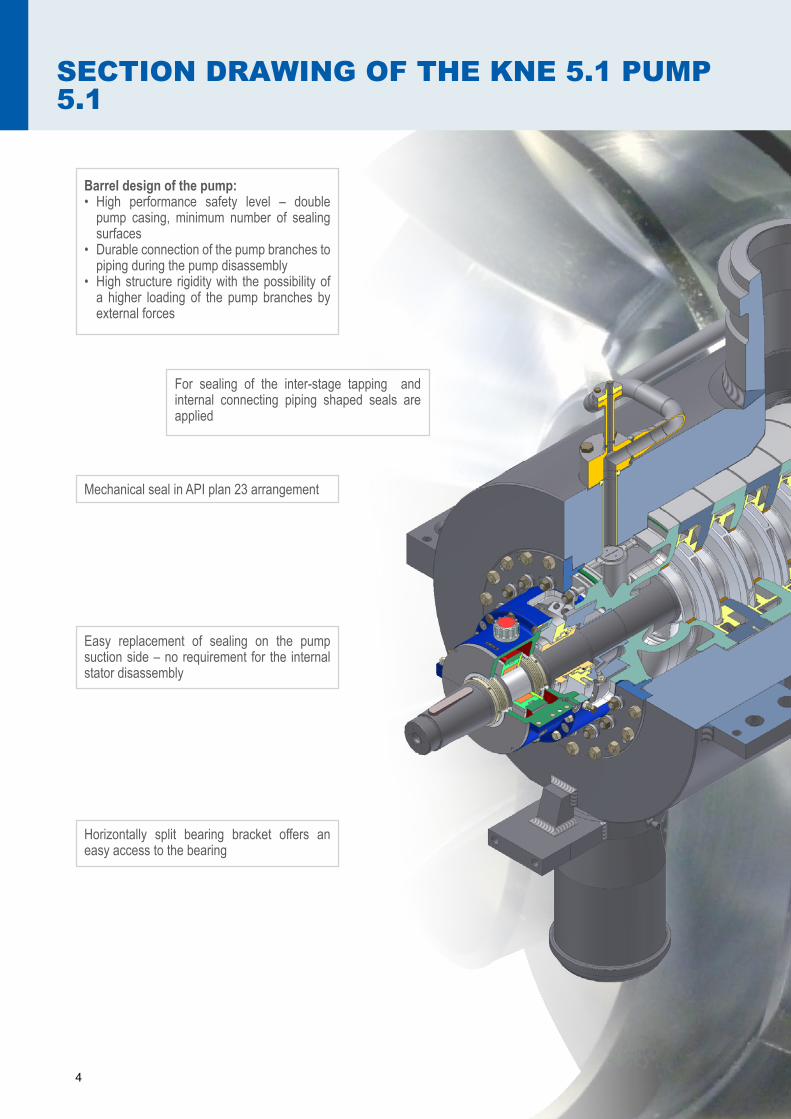
SECTION DRAWING OF THE KNE 5.1 PUMP 5.1
Barrel design of the pump:• High performance safety level – double
pump casing, minimum number of sealing surfaces
• Durable connection of the pump branches to piping during the pump disassembly
• High structure rigidity with the possibility of a higher loading of the pump branches by external forces
For sealing of the inter-stage tapping and internal connecting piping shaped seals are applied
Easy replacement of sealing on the pump suction side – no requirement for the internal stator disassembly
Horizontally split bearing bracket offers an easy access to the bearing
Mechanical seal in API plan 23 arrangement

5
Feet in the pump axe
Hydraulically stretched stator bolts
Two-sided axial bearing
Horizontally split bearing bracket
Pump housing cover sealed by graphite rings
Firmly bolted stage bodies creating an inte-grated unit
Hydraulic parts accurately cast from Cr-Ni steel

6
PUMP DESIGN VERIFICATION
The computer simulation of the pump cold start is
applied for an optimisation of the pump design
Tension run during the pump cold start Temperature array during the pump cold start
The pump design is verified by computational methods and optimised from the point of view of the material tension, parts deformations, dynamic carriage of the pump rotor as well as of the complete pump incl. its base frame.

7
PUMP DIMENSIONS
TYPE DN1 DN2 A B C D E F G H Weight (kg)
KNE-4.1 7st 300 300 2715 200 1805 1010 1100 900 650 0 9 870
KNE-4.1 8st 300 300 2840 200 1930 770 1100 850 650 0 10 750
KNE-5.1 6st 300 300 3050 250 1615 790 1200 1070 1065 45° 14 600
INTERNAL STATOR
Advantages:• The internal stator is assembled out of the
pump barrel.• Before the internal stator installation
mechanical seals are adjusted and the pump rotor is in the correct working position.
• Easy pump internal stator replacement by means of special assembly tool delivered to gether with the pump.
The pump internal stator is supplied as spare part. Sample of assembly of the pump internal stator into the pump housing.

44+0.1-0.1
Ø350
Ø240 r6
Ø215
Ø230 r6
Ø50
+0.3
0
45 45
184.5 0-0.1
Ø240
R3
1x45° 1x45°
(Ø70)
Ø200
10°
(Ø184) Ø
90 h9
45R10
10°R10
Ø65 H7 9.5
+0.1 0
1x45° (98)A
(77)
23
3,2
3,23,275
0-0.2
7.51.5x45° 1.5x45°
107(77.5)
7.5
b0,02/Ø70A
6.5 0-0.5
1,6
Ø250
48
1,6
h0,03A
1,6
3,2
203,2
1X45°
h0,03/Ø70A
53
h0,01A
R15
18 D9
36.7
+0.4
+0.2
R0.6
Ø90
3,2
7xØ7
7 LOPATEK
40
R5
R30h0,03A
155 17
2
42R58
20
b0,02/Ø55A5°
44+0.1-0.1
Ø35
0
Ø24
0 r6
Ø21
5
Ø23
0 r6
Ø50
+0.3
0
4545
184.5 0-0.1
Ø24
0
R3
1x45°1x45°
(Ø70
)
Ø20
0
10°
(Ø18
4)Ø90
h9
45R10
10°R10
Ø65
H79.5
+0.1 0
1x45°(98) A
(77)
23
3,2
3,2 3,2
75 0-0.2
7.51.5x45°1.5x45°
107 (77.5)
7.5
b 0,02/Ø70A
6.5 0-0.5
1,6
Ø25
0
48
1,6
h 0,03 A
1,6
3,2
203,2
1X45°
h 0,03/Ø70A
53
h 0,01A
R15
18 D9
36.7
+0.4
+0.2
R0.6
Ø90
3,2
7xØ7
7 LOPATEK
40
R5
R30
h 0,03 A
15517
2
42R58
20
b 0,02/Ø55 A 5°
1.
2.
1. Power Plant Tušimice (CZ), KNE 4.12. Power Plant Ledvice (CZ), KNE 5.1


www.sigma.cz
SIGMA GROUP a. s.Jana Sigmunda 79
783 49 Lutín, Czech Republic+420 585 652 011, +420 585 652 060+420 585 652 051, +420 585 944 294
Ostrava
Praha
Brno


