KMART norules fengmian · The correct frame size is the largest frame that the rider can...
28
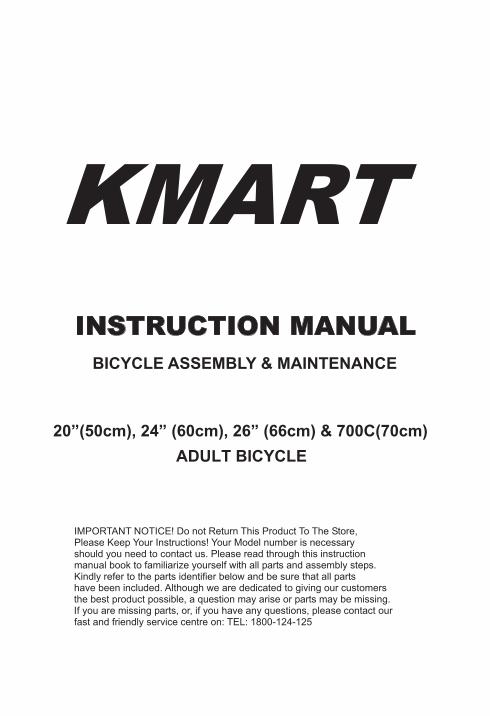
KMART I N S T R U C T I O N M A N U A L BICYCLE ASSEMBLY & MAINTENANCE 20”(50cm), 24” (60cm), 26” (66cm) & 700C(70cm) ADULT BICYCLE IMPORTANT NOTICE! Do not Return This Product To The Store, Please Keep Your Instructions! Your Model number is necessary should you need to contact us. Please read through this instruction manual book to familiarize yourself with all parts and assembly steps. Kindly refer to the parts identifier below and be sure that all parts have been included. Although we are dedicated to giving our customers the best product possible, a question may arise or parts may be missing. If you are missing parts, or, if you have any questions, please contact our fast and friendly service centre on: TEL: 1800-124-125
Transcript of KMART norules fengmian · The correct frame size is the largest frame that the rider can...
KMART INSTRUCTION MANUAL
BICYCLE ASSEMBLY & MAINTENANCE
20”(50cm), 24” (60cm), 26” (66cm) & 700C(70cm)ADULT BICYCLE
IMPORTANT NOTICE! Do not Return This Product To The Store, Please Keep Your Instructions! Your Model number is necessary should you need to contact us. Please read through this instruction manual book to familiarize yourself with all parts and assembly steps. Kindly refer to the parts identifier below and be sure that all parts have been included. Although we are dedicated to giving our customers the best product possible, a question may arise or parts may be missing. If you are missing parts, or, if you have any questions, please contact our fast and friendly service centre on: TEL: 1800-124-125
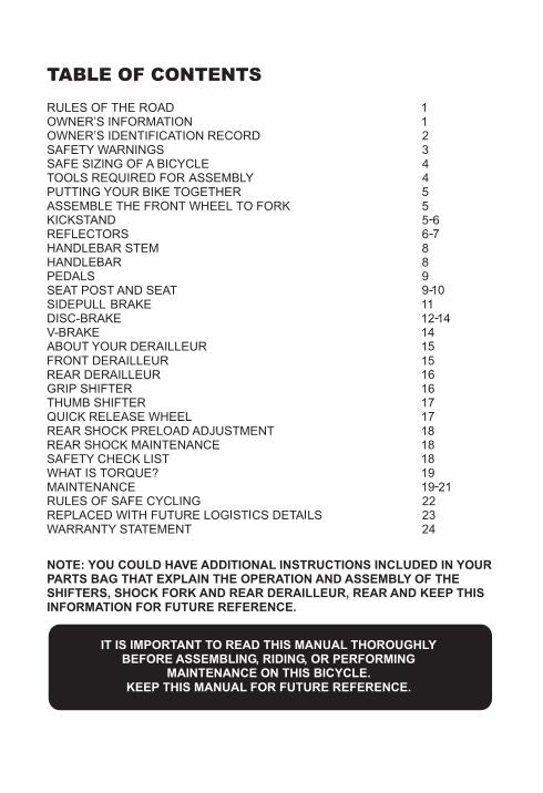
TABLE OF CONTENTS
RULES OF THE ROAD OWNER’S INFORMATION OWNER’S IDENTIFICATION RECORD SAFETY WARNINGS SAFE SIZING OF A BICYCLE TOOLS REQUIRED FOR ASSEMBLY PUTTING YOUR BIKE TOGETHER ASSEMBLE THE FRONT WHEEL TO FORKKICKSTAND
REFLECTORS HANDLEBAR STEMHANDLEBARPEDALS SEAT POST AND SEATSIDEPULL BRAKEDISC-BRAKEV-BRAKEABOUT YOUR DERAILLEUR
GRIP SHIFTER
WHAT IS TORQUE?
THUMB SHIFTER
SAFETY CHECK LIST
QUICK RELEASE WHEELREAR SHOCK PRELOAD ADJUSTMENTREAR SHOCK MAINTENANCE
MAINTENANCERULES OF SAFE CYCLING
FRONT DERAILLEURREAR DERAILLEUR
WARRANTY STATEMENT
NOTE: YOU COULD HAVE ADDITIONAL INSTRUCTIONS INCLUDED IN YOUR PARTS BAG THAT EXPLAIN THE OPERATION AND ASSEMBLY OF THE SHIFTERS, SHOCK FORK AND REAR DERAILLEUR, REAR AND KEEP THIS INFORMATION FOR FUTURE REFERENCE.
IT IS IMPORTANT TO READ THIS MANUAL THOROUGHLY BEFORE ASSEMBLING, RIDING, OR PERFORMING
MAINTENANCE ON THIS BICYCLE. KEEP THIS MANUAL FOR FUTURE REFERENCE.
1. IN THE INTEREST OF SAFER CYCLING, MAKE SURE YOU READ ANDUNDERSTAND YOUR OWNER’S MANUAL.
2. NOTICE: Some state and local traffic laws may require that your bicycle be equippedwith a warning device, such as a horn or bell and a light, if the bicycle is to be riddenafter dark.
3. Always wear shoes when riding a bicycle and avoid loose fitting clothes.4. CAUTION: WET WEATHER WARNING: Check your brakes frequently. The ability to
stop your bicycle is critical. Roads are slippery in wet weather so avoid sharp turns andallow more distance for stopping. Caliper brakes may become less efficient when wet.Leaves, loose gravel and other debris on the road can also effect stopping distance.
5. The kickstand is designed to support the bicycle only. Not the rider.6. Replace bent or broken spokes, and bent or damaged wheel rims.7. Obey all traffic regulations. Most traffic regulations apply to bike riders as well as
automobile operators.8. Follow the traffic flow in a straight line close to the curb. Watch for cars moving in and
out of traffic.9. Always ride alone. Never carry other riders. This is dangerous and it makes the bicycle
harder to control.10. When riding in pairs or in larger groups, from a single line along the right side of road.
Set up a sensible distance between riders. Don’t tailgate.11. Always be alert. Animals or people may dart in front of you. Be on the alert. People
have the right of way. Be alert to people opening car doors when passing parked cars.Your bicycle was not designed for stunting and experimentation. Enjoy riding it in a safemanner.
12. Be careful at all intersections. Slow down and look both ways before crossing.13. Use hand signals. Always let other drivers and pedestrians know what you are going to
do. Signal 100 ft(30.48 cm). before turning unless your hand is needed to control thebike.
14. CAUTION: NIGHT TIME OPERATION: We do NOT recommend riding your bike atnight. If you have an emergency that makes it necessary to ride at right, have properlights and reflectors. Do NOT ride at night without a headlight, taillight, a white frontreflector, a red rear reflector and yellow wheel reflectors.
15. Do not carry packages or objects which obstruct vision.16. Never hitch rides. Never hold onto moving vehicles while riding. Never Stunt.17. ON AND OFF ROAD OPERATION: Avoid the following hazards: drain grates, pot holes,
ruts, soft road edges, gravel, and leaves especially when they are wet.
OWNER’S INFORMATIONThroughout this manual you will find WARNINGS, CAUTIONS and NOTES or NOTICES.WARNINGS: Pay special attention to these since failure to do so could result in injury to therider or others.CAUTIONS: If not followed these could result in mechanical failure or damage.NOTES OR NOTICES: These specify something that is of special interest.
Owner’s information continued next page.
RULES OF THE ROAD
1
OWNER’S INFORMATION continued
It is the responsibility of the person who initially assembles the bicycle to do so correctly andmake any necessary adjustments for proper operations. The owner or principal rider is thenresponsible for normal maintenance of the bicycle to keep it in good condition.1. Make certain that all assembly instructions and necessary adjustments have been
followed.2. Perform the safety check list and mark each item listed.3. Know how to operate all standard and accessory equipment on the bicycle.4. Make certain that anyone who uses the bicycle has been fully instructed in its operation.5. If your bicycle was obtained assembled, we recommend that you review the complete
assembly instructions and perform checks specified in this manual before riding thebicycle.
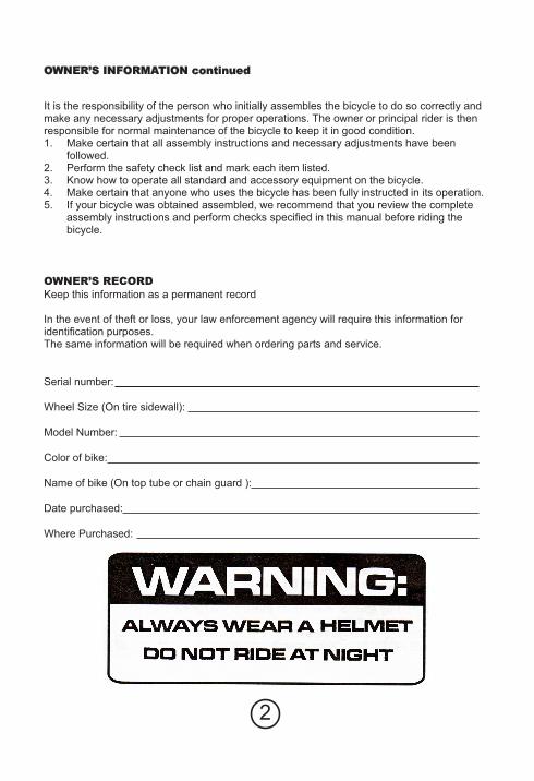
OWNER’S RECORDKeep this information as a permanent record
In the event of theft or loss, your law enforcement agency will require this information foridentification purposes.The same information will be required when ordering parts and service.
Serial number:
Wheel Size (On tire sidewall):
Model Number:
Color of bike:
Name of bike (On top tube or chain guard ):
Date purchased:
Where Purchased:
2
Before you ride, please read all the following items making sure you understand them.Failure to do so could cause damage to the bicycle or possible injury to yourself or others.Your bicycle meets or exceeds industry standards. It is NOT designed for off-road use,Jumping, stunts and other types of abusive riding.
BRAKE PRECAUTIONS1. Do not ride the bicycle until you have checked for proper brake adjustments See “Hand
brake lever Assembly” and “Caliper Brake Adjustment” Sections.2. When riding your bicycle of the first time. Test the brakes at a slow speed on a large
level surface without obstructions. Also, never attempt to stop suddenly using the frontbrake only, as this could throw the rider off the front of the bicycle.
3. Check and adjust the brakes, if necessary, at the first sign of failure. This will enable therider to make a quick and smooth stop. On caliper brakes, if a brake lever touches thegrip when it is squeezed, adjust the brakes.
4. Going downhill fast is dangerous since you can’t stop nearly as fast as you can on levelaround. A curve at the bottom of a hill could force you into oncoming traffic or off theroad if you are going at an excessive speed.
5. Use the front brake slowly and carefully, especially while turning or when the road is wetor covered with gravel, sand or leaves. Start braking sooner under these conditions andwith less force to reduce the chances of skidding. Wet brake shoes mean that it willrequire more distance to stop. Start braking sooner than normal in wet conditions.
6. Nighttime riding:a. You can’t see the controls on your bicycle at night so you must know where they
are by touch.b. Slow down. Debris and holes are much harder to see at night.c. If possible, ride on streets that are familiar to you. Terrain that you have never seen
during the day is dangerous at night.d. Use well lighted streets whenever possible. Avoid unlighted bike paths.e. Comply with all legal requirements in your state. You should at least have a “white
light”. (not just a white reflector) On the front and a rear red reflector. All statesrequire that lamp be used that emits a white light.
f. Children generally should not be allowed to ride a bicycle at night or during periods of lowvisibility such as dawn, dusk or bad weather. Adults should avoid night riding if possible.
g. It is a good idea day or night to wear a helmet and have a rear view mirror.7. If the stem is not inserted into the head tube to at least the minimum insertion line, it is
possible to over-tighten the handlebar stem bolt and damage the fork stem body. Thiscould cause an unsafe condition and risk injury to the rider.
8. For safe operations, you must secure the pedal spindle tightly against the crank armwith a wrench that fits the shoulder of the pedal spindle. This is important: it avoidsstripping threads. Always replace damage pedals.
9. When adjusting the seat height, you must have the minimum insertion mark on the seatpost inserted inside the frame.
SAFETY WARNINGS
3
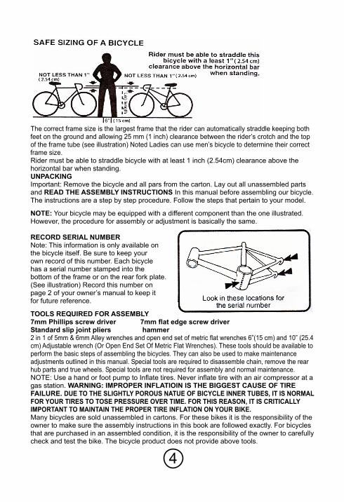
The correct frame size is the largest frame that the rider can automatically straddle keeping bothfeet on the ground and allowing 25 mm (1 inch) clearance between the rider’s crotch and the topof the frame tube (see illustration) Noted Ladies can use men’s bicycle to determine their correctframe size.Rider must be able to straddle bicycle with at least 1 inch (2.54cm) clearance above thehorizontal bar when standing.UNPACKINGImportant: Remove the bicycle and all pars from the carton. Lay out all unassembled partsand READ THE ASSEMBLY INSTRUCTIONS In this manual before assembling our bicycle.The instructions are a step by step procedure. Follow the steps that pertain to your model.
NOTE: Your bicycle may be equipped with a different component than the one illustrated.However, the procedure for assembly or adjustment is basically the same.
RECORD SERIAL NUMBERNote: This information is only available onthe bicycle itself. Be sure to keep yourown record of this number. Each bicyclehas a serial number stamped into thebottom of the frame or on the rear fork plate.(See illustration) Record this number onpage 2 of your owner’s manual to keep itfor future reference.
TOOLS REQUIRED FOR ASSEMBLY7mm Phillips screw driver 7mm flat edge screw driverStandard slip joint pliers hammer2 in 1 of 5mm & 6mm Alley wrenches and open end set of metric flat wrenches 6”(15 cm) and 10” (25.4cm) Adjustable wrench (Or Open End Set Of Metric Flat Wrenches). These tools should be available toperform the basic steps of assembling the bicycles. They can also be used to make maintenanceadjustments outlined in this manual. Special tools are required to disassemble chain, remove the rearhub parts and true wheels. Special tools are not required for assembly and normal maintenance.NOTE: Use a hand or foot pump to Inflate tires. Never inflate tire with an air compressor at agas station. WARNING: IMPROPER INFLATIOIN IS THE BIGGEST CAUSE OF TIREFAILURE. DUE TO THE SLIGHTLY POROUS NATUE OF BICYCLE INNER TUBES, IT IS NORMALFOR YOUR TIRES TO TOSE PRESSURE OVER TIME. FOR THIS REASON, IT IS CRITICALLYIMPORTANT TO MAINTAIN THE PROPER TIRE INFLATION ON YOUR BIKE.Many bicycles are sold unassembled in cartons. For these bikes it is the responsibility of theowner to make sure the assembly instructions in this book are followed exactly. For bicyclesthat are purchased in an assembled condition, it is the responsibility of the owner to carefullycheck and test the bike. The bicycle product does not provide above tools.
4
6
REMOVE BIKE FROM CARTONBe sure all parts are removed from carton. Check before you discard the carton. Remove allprotective packing material.
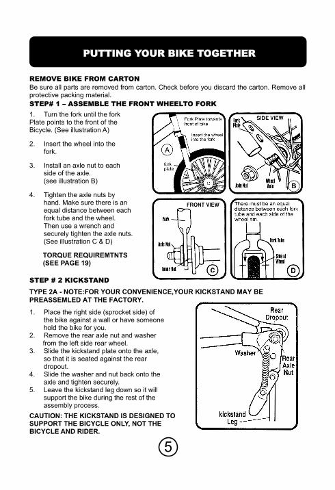
STEP# 1 – ASSEMBLE THE FRONT WHEELTO FORK
1. Turn the fork until the forkPlate points to the front of theBicycle. (See illustration A)
2. Insert the wheel into thefork.
3. Install an axle nut to eachside of the axle.(see illustration B)
4. Tighten the axle nuts byhand. Make sure there is anequal distance between eachfork tube and the wheel.Then use a wrench andsecurely tighten the axle nuts.(See illustration C & D)
TORQUE REQUIREMTNTS(SEE PAGE 19)
STEP # 2 KICKSTAND
1. Place the right side (sprocket side) ofthe bike against a wall or have someonehold the bike for you.
2. Remove the rear axle nut and washerfrom the left side rear wheel.
3. Slide the kickstand plate onto the axle,so that it is seated against the reardropout.
4. Slide the washer and nut back onto theaxle and tighten securely.
5. Leave the kickstand leg down so it willsupport the bike during the rest of theassembly process.
CAUTION: THE KICKS
TYPE 2A - NOTE:FOR YOUR CONVENIENCE,YOUR KICKSTAND MAY BE
PREASSEMLED AT THE FACTORY.
TAND IS DESIGNED TOSUPPORT THE BICYCLE ONLY, NOT THEBICYCLE AND RIDER.
PUTTING YOUR BIKE TOGETHER
5
6
NOTE: YOUTYPE 2B -
TYPE 3A -
TYPE 3B
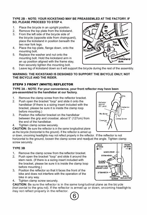
R KICKSTAND MAY BE PREASSEMLED AT THE FACTORY. IFSO, PLEASE PROCEED TO STEP 4.
1. Place the bicycle in an upright position.2. Remove the top plate from the kickstand.3. From the left side of the bicycle side of
the bicycle (opposite side from chainguard),place the kickstand in position beneath thetwo rear fork legs.
4. Place the top plate, flange down, onto themounting bolt.
5. Replace the washer and nut onto themounting bolt. Hold the kickstand arm inan up position aligned with the frame stay,then securely tighten the mounting bolt.
6. Leave leg of kickstand down so it will support the bicycle during the rest of the assembly.
WARNING: THE KICKSTAND IS DESIGNED TO SUPPORT THE BICYCLE ONLY; NOTTHE BICYCLE AND THE RIDER.
STEP# 3 FRONT (WHITE) REFLECTOR
NOTE: For your convenience, your front reflector may have beenpre-assembled to the handlebar at our factory.
1. Remove the clamp screw from the reflector bracket.2. Push open the bracket “loop” and slide it onto the
handlebar (If there is a sizing insert included with the bracket, please be sure it is inside the clamp loopbefore mounting.)
3. Position the reflector bracket on the handlebarbetween the grip and crossbar, about 5” (127cm) fromthe end of the handlebar.
4. Tighten clamp screw securely.CAUTION: Be sure the reflector is in the same longitudinal planeas the bicycle (horizontal to the ground). If the reflector is aimed upor down, oncoming headlights may not reflect properly in the reflector. If the reflector is nothorizontal to the ground, loosen the clamp screw and readjust the angle. Tighten clampscrew securely.
1. Remove the clamp screw from the reflector bracket.2. Push open the bracket “loop” and slide it around the
stem neck. (If there is a sizing insert included with
the bracket, please be sure it is inside the clamp loopbefore mounting.)
3. Position the reflector so that it faces the front of thebike and does not interfere with the operation of thebike in any way.
4. Tighten clamp screw securely.
CAUTION: Be sure the reflector is in the same longi tudinal plane as the bic ycle(hori zontal to the grou nd). If the reflec tor is armed up or down, oncoming headligh tsmay not reflect properly in the reflector.
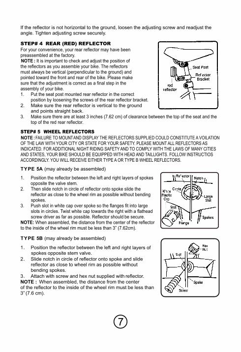
STEP# 4 REAR (RED) REFLECTORFor your convenience, your rear reflector may have beenpreassembled at the factory.NOTE : It is important to check and adjust the position ofthe reflectors as you assemble your bike. The reflectorsmust always be vertical (perpendicular to the ground) andpointed toward the front and rear of the bike. Please makesure that the adjustment is correct as a final step in theassembly of your bike.1. Put the seat post mounted rear reflector in the correct
position by loosening the screws of the rear reflector bracket.2. Make sure the rear reflector is vertical to the ground
and points straight back.3. Make sure there are at least 3 inches (7.62 cm) of clearance between the top of the seat and the
top of the red rear reflector.
STEP# 5 WHEEL REFLECTORSNOTE : FAILURE TO MOUNTAND DISPLAY THE REFLECTORS SUPPLIED COULD CONSTITUTE A VOILATIONOF THE LAW WITH YOUR CITY OR STATE FOR YOUR SAFETY. PLEASE MOUNT ALL REFLECTORS ASINDICATED. FOR ADDITIONAL NIGHT RIDING SAFETY AND TO COMPLY WITH THE LAWS OF MANY CITIESAND STATES, YOUR BIKE SHOULD BE EQUIPPED WITH HEAD AND TAILLIGHTS. FOLLOW INSTRUCTIOSACCORDINGLY. YOU WILL RECEIVE EITHER TYPE A OR TYPE B WHEEL REFLECTORS.
TYPE 5A (may already be assembled)
TYPE 5B (may already be assembled)
1. Position the reflector between the left and right layers of spokesopposite the valve stem.
2. Then slide notch in circle of reflector onto spoke slide thereflector as close to the wheel rim as possible without bendingspokes.
3. Push slot in white cap over spoke so the flanges fit into largeslots in circles. Twist white cap towards the right with a flatheacrew driver as far as possible. Reflector should be secure.
NOTE: When assembled, the distance from the center of the reflectorto the inside of the wheel rim must be less than 3” (7.62cm).
7
If the reflector is not horizontal to the ground, loosen the adjusting screw and readjust theangle. Tighten adjusting screw securely.
1 Position the reflector between the left and right layers ofspokes opposite stem valve.
2 Slide notch in circle of reflector onto spoke and slidereflector as close to wheel rim as possible withoutbending spokes.
3 Attach with screw and hex nut supplied with reflector.
NOTE : When assembled, the distance from the centerof the reflector to the inside of the wheel rim must be less than3” (7.6 cm).
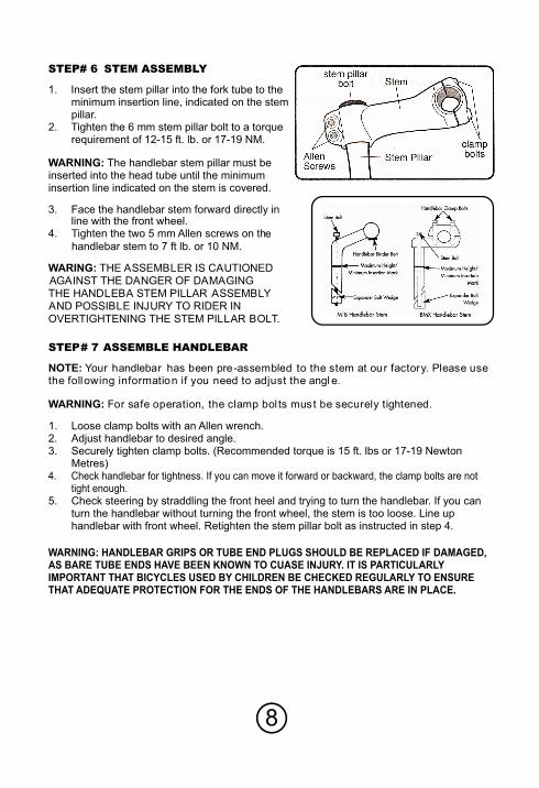
STEP# 6 STEM ASSEMBLY
1. Insert the stem pillar into the fork tube to theminimum insertion line, indicated on the stempillar.
2. Tighten the 6 mm stem pillar bolt to a torquerequirement of 12-15 ft. lb. or 17-19 NM.
WARNING: The handlebar stem pillar must beinserted into the head tube until the minimuminsertion line indicated on the stem is covered.
3. Face the handlebar stem forward directly inline with the front wheel.
4. Tighten the two 5 mm Allen screws on thehandlebar stem to 7 ft lb. or 10 NM.
WARING: THE ASSEMBLER IS CAUTIONEDAGAINST THE DANGER OF DAMAGINGTHE HANDLEBA STEM PILLAR ASSEMBLYAND POSSIBLE INJURY TO RIDER INOVERTIGHTENING THE STEM PILLAR BOLT.
STEP# 7 ASSEMBLE HANDLEBAR
NOTE: Your handlebar has been pre-assembled to the stem at our factory. Please usethe following information if you need to adjust the angl e.
WARNING: For safe operation, the clamp bol ts must be securely tightened.
1. Loose clamp bolts with an Allen wrench. 2. Adjust handlebar to desired angle.3. Securely tighten clamp bolts. (Recommended torque is 15 ft. lbs or 17-19 Newton
Metres)4. Check handlebar for tightness. If you can move it forward or backward, the clamp bolts are not
tight enough.5. Check steering by straddling the front heel and trying to turn the handlebar. If you can
turn the handlebar without turning the front wheel, the stem is too loose. Line uphandlebar with front wheel. Retighten the stem pillar bolt as instructed in step 4.
WARNING: HANDLEBAR GRIPS R TUBE END PLUGS S BE REPLACED IF DAMAGED,AS BARE TUBE ENDS HAVE BEEN KNOWN TO CUASE INJURY. IT IS PARTICULARLYIMPORTANT THAT BICYCLES USED BY CHILDREN BE CHECKED REGULARLY TO ENSURETHAT ADEQUATE PROTECTION FOR THE ENDS OF THE HANDLEBARS ARE IN PLACE.
8
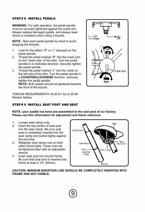
STEP# 8 INSTALL PEDALS
WARNING: For safe operation, the pedal spindlemust be securely tightened against the crank arm.Always replace damaged pedals, and always wearshoes or sneakers when riding a bicycle.
NOTE : Start each pedal spindle by hand to avoidstripping the threads.
1. Look for the letters “R” or “L” stamped on thepedal spindle.
2. Thread the pedal marked “R” into the crank armon the “chain side” of the bike. Turn the pedalspindle in a clockwise direction. Securely tightenthe pedal spindle.
3. Thread the pedal marked “L” into the crank onthe left side of the bike. Turn the pedal spindle ina COUNTERCLOCKWISE direction. Securelytighten the pedal spindle.NOTE: Both pedals should be tightened towardsthe front of the bicycle.
TORQUE REQUIREMENTS 18-20 ft-1 bs or 20-26Newton Netres.
STEP# 9 INSTALL SEAT POST AND SEAT
NOTE: your saddle has been pre-assembled to the seat post at our factory.
Please use this information for adjustment and future reference.
1. Loosen seat clamp nuts.2. Insert the top portion of seat post
into the seat clamp. Be sure seatpost is completely inserted into theseat clamp and butted tightly againstthe end stop.
3. Retighten seat clamp nuts on bothsides (Hand tight). These nuts willbe tightened later with an adjustablewrench.
4. Insert seat post into bicycle frame.Be sure that seat post is inserted intoframe at least 2 1/2” (65mm).
CAUTION: MININUM INSERTION LINE SHOULD BE COMPLETELY INSERTED INTOFRAME AND NOT VISIBLE.
9
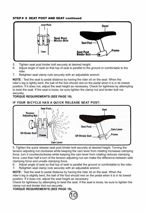
STEP# 9 SEAT POST AND SEAT continued
5. Tighten seat post binder bolt securely at desired height.6. Adjust angle of seat so that top of seat is parallel to the ground or comfortable to the
rider.7. Retighten seat clamp nuts securely with an adjustable wrench.
NOTE : Test the seat to pedal distance by having the rider sit on the seat. When therider’s leg is lightly bent, the ball of the foot should rest on the pedal when it is in its lowestposition. If it does not, adjust the seat height as necessary. Check for tightness by attemptingto twist the seat. If the seat is loose, be sure tighten the clamp nut and binder bolt nutsecurely.TORQUE REQUIREMENTS (SEE PAGE 19).
IF YOUR BICYCLE HA S A QU ICK RELEASE SEAT POST:
5. Tighten the quick release seat post binder bolt securely at desired height. Turning thetension adjusting nut clockwise while keeping the cam lever from rotating increases clampingforce, turn it counterclockwise while keeping the cam lever from rotating reduces clampingforce. Less than half a turn of the tension adjusting nut can make the difference between safeclamping force and unsafe clamping force.6. Adjust angle of seat so that top of seat is parallel the ground or comfortable to the rider.7. Retighten seat clamp nuts securely with an adjustable wrench.
NOTE : Test the seat to pedal distance by having the rider sit on the seat. When therider’s leg is slightly bent, the ball of the foot should rest on the pedal when it is in its lowestposition. If it does not, adjust the seat height as necessary.Check for tightness by attempting to twist the seat. If the seat is loose, be sure to tighten theclamp nut and binder blot nut securely.TORQUE REQUIREMENTS (SEE PAGE 19).
10
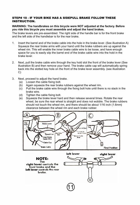
STEP# 10 -
WARNING: The handbrakes on this bicycle were NOT adjusted at the factory. Beforeyou ride this bicycle you must assemble and adjust the hand brakes.
The brake levers are pre-assembled. The right side of the handle bar is for the front brakeand the left side of the handlebar is for the rear brake.
1. Insert the barrel and of the brake cable into the hole in the brake lever. (See illustration A)Squeeze the rear brake arms with your hand until the brake rubbers are up against thewheel rim. This will enable the inner brake cable wire to be loose, and have enoughspace for you to easily slip the barrel end of the brake cable wire into the hold in thebrake lever.
2. Next, pull the brake cable wire through the key hold slot the front of the brake lever (Seeillustration B) and then remove your hand. The brake cable cap will automatically springback into the slotted key hole on the front of the brake lever assembly. (see illustrationC)
3. Next, proceed to adjust the hand brake.(a) Loosen the cable fixing bolt.(b) Again squeeze the rear brake rubbers against the wheel rim.(c) Pull the brake cable wire through the fixing bolt hole until there is no slack in the
brake wire.(d) Tighten the cable fixing bolt.(e) Squeeze the brake lever hard and then release several times. Rotate the rear
wheel, be sure the rear wheel is straight and does not wobble. The brake rubbersshould not touch the wheel rim, and there should be about 1/16 inch (1.6mm)clearance between the wheel rim and each brake rubber.
11

IF THE BRAK E RUBBERS TOUCH THE WHEEL RIM
Loosen the anchor bolt nut and let the brake rubbers spring open a little, to clear the wheelrim. Retighten the anchor bolt nut and squeeze and release the brake lever.Check the clearance again. Repeat the adjustment if necessary.
NOTE: If additional brake adjusting is required – you can bring the brake rubber closer to thewheel rim by turning the adjusting screw counterclockwise. To move the brake rubbersfurther from the rim, turn the adjusting screw clockwise. Be sure the cable is locked securelythrough the anchor bolt. (See illustration D). Reset cable adjuster lock nut when adjustmentis final.
WARNING: If after brake adjustments are made, and the hand brake still does not function,then have brake repaired or adjusted at a bicycle service shop.Do not ride if brakes do not function properly.
12
IF YOUR BIKE HAS DISC-BRAKE OR V-BRAKE
WARNING: These brakes are highly sensitive and extremely powerful. Before using yournew brakes, be sure that you are completely familiar with their operation. Practice your ridingand braking techniques on a flat level surface at slow speeds prior to attempting any highspeed or off road maneuvers.
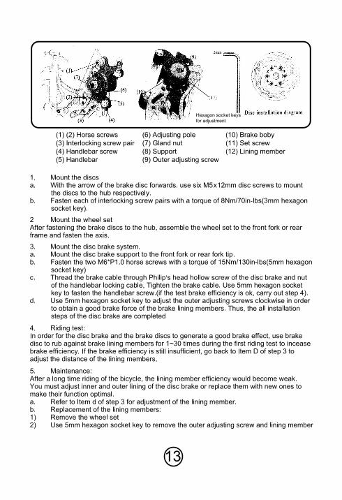
13
(1) (2) Horse screws
(3) Interlocking screw pair
(4) Handlebar screw
(5) Handlebar
(6) Adjusting pole
(7) Gland nut
(8) Support
(9) Outer adjusting screw
(10) Brake boby
(11) Set screw
(12) Lining member
Hexagon socket keys
for adjustment
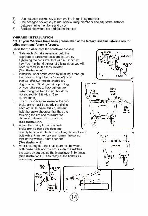
V-BRAKE INSTALLATIONNOTE: your V-brakes have been pre-Installed at the factory, use this information foradjustment and future reference.
Install the v-brakes onto the cantilever bosses:
1. Slide each V-Brake assembly onto theappropriate cantilever boss and secure bytightening the cantilever blot with a 5 mm hexkey. You may hand tighten at this point as you willneed to readjust the tension later.(See illustration A)
2. Install the inner brake cable by pushing it throughthe cable routing tube (or “noodle”) notethat we offer two noodle angles (90degrees and 135 degrees) dependingon your bike setup. Now tighten thecable fixing bolt to a torque that doesnot exceed 9-12 ft. –lbs. (Seeillustration B)
3. To ensure maximum leverage the twobrake arms must be nearly parallel toeach other. To make this adjustment,hold the brake shoes so that they aretouching the rim and measure thedistance between points a and b. (See illustration C)
4. Adjust the spring tension in eachbrake arm so that both sides areequally tensioned. Do this by holding the cantileverbolt with a 5mm hex key and turning the springtension nut with a 23mm spanner.(See illustration D)
5. After ensuring that the total clearance betweenboth brake pads and the rim is 2-3mm stretchesthe cable by squeezing the brake lever 5-10 times.(See illustration E) Then readjust the brakes asnecessary.
14
ABOUT YOUR DERAILLEUROPERATON OF DERAILLURS: Changing gears gives you more efficient pedaling effort. Toomuch pressure means change to lower gear. If pedaling is too easy, change to a higher gear.CAUTION: don’t force the shifter. Shifters should move easily and the chain should moveeasily from one sprocket to another. Please observe the following when shifting.Reduce pedaling pressure while shifting.Shift only when pedals & wheels are in motion.Never pedal backwards while shifting gears.Never force shifters.
HOW IT WORKSWhen the right shift lever is shifted, the pulley guide or derail the chain allowing it to move toa different sprocket in the rear sprocket cluster. The derailleur cage is spring loaded. It keepsthe chain tight, but gives as the chain moves from one sprocket to another.
MAKING ADJUSTMENTS
15
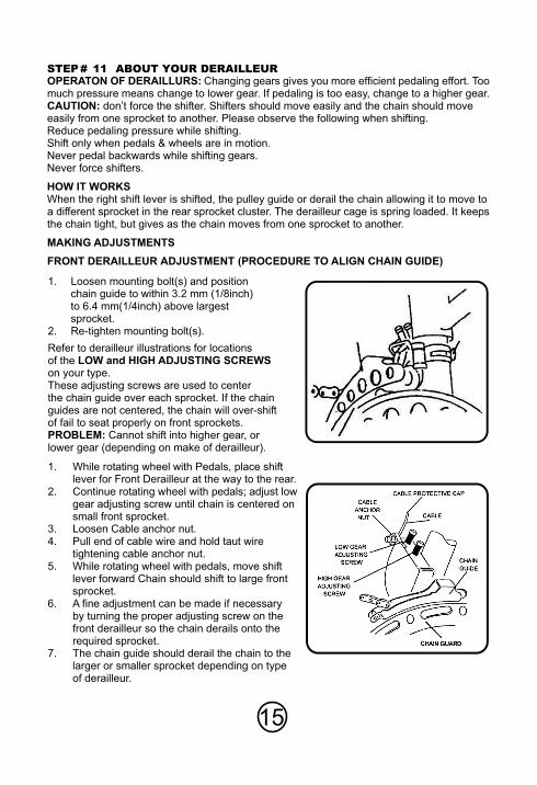
FRONT DERAILLEUR ADJUSTMENT (PROCEDURE TO ALIGN CHAIN GUIDE)
1. Loosen mounting bolt(s) and positionchain guide to within 3.2 mm (1/8inch)to 6.4 mm(1/4inch) above largestsprocket.
2. Re-tighten mounting bolt(s).
Refer to derailleur illustrations for locationsof the LOW and HIGH ADJUSTING SCREWSon your type.These adjusting screws are used to centerthe chain guide over each sprocket. If the chainguides are not centered, the chain will over-shiftof fail to seat properly on front sprockets.PROBLEM: Cannot shift into higher gear, orlower gear (depending on make of derailleur).
1. While rotating wheel with Pedals, place shiftlever for Front Derailleur at the way to the rear.
2. Continue rotating wheel with pedals; adjust lowgear adjusting screw until chain is centered onsmall front sprocket.
3. Loosen Cable anchor nut.4. Pull end of cable wire and hold taut wire
tightening cable anchor nut.5. While rotating wheel with pedals, move shift
lever forward Chain should shift to large frontsprocket.
6. A fine adjustment can be made if necessaryby turning the proper adjusting screw on thefront derailleur so the chain derails onto therequired sprocket.
7. The chain guide should derail the chain to thelarger or smaller sprocket depending on typeof derailleur.
STEP# 11
16
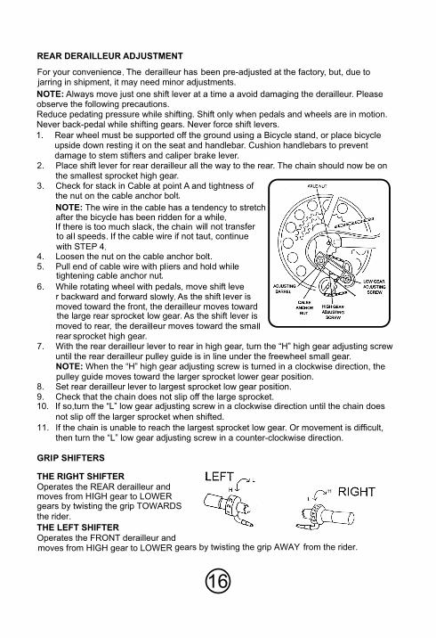
2. Place shift lever for rear derailleur all the way to the rear. The chain should now be onthe smallest sprocket high gear.
3. Check for stack in Cable at point A and tightness
NOTE:
4. Loosen the nut on the cable anchor bolt.5. Pull end of cable wire wi
6. While rotating wheel with p
he front, the derailleur moves to
sprocket high gear.7. With the rear derailleur lever to rear in high gear, turn the “H” high gear adjusting screw
until the rear derailleur pulley guide is in line under the freewheel small gear.NOTE: When the “H” high gear adjusting screw is turned in a clockwise direction, thepulley guide moves toward the larger sprocket lower gear position.
8. Set rear derailleur lever to largest sprocket low gear position.9. Check that the chain does not slip off the large sprocket.
11. If the chain is unable to reach the largest sp
10. If so,turn the “L” low gear adjusting screw in a clockwise direction until the chain does
not slip off the larger sprocket when shifted.
rocket low gear. Or movement is difficult,then turn the “L” low gear adjusting screw in a counter-clockwise direction.
REAR DERAILLEUR ADJUSTMENT
illeur has been pre-adjusted at the factory, but, due tojarring in shipment, it may need minor ad
djustments.
NOTE: Always move just one shift lever at a time a avoid damaging the derailleur. Pleaseobserve the following precautions.Reduce pedating pressure while shifting. Shift only when pedals and wheels are in motion.Never back-pedal while shifting gears. Never force shift levers.
1. Rear wheel must be supported off the ground using a Bicycle stand, or place bicycleupside down resting it on the seat and handlebar. Cushion handlebars to preventdamage to stem stifters and caliper brake lever.
GRIP SHIFTERS
THE RIGHT SHIFTER
Operates the REAR derailleur andmoves from HIGH gear to LOWERgears by twisting the grip TOWARDS
the rider.
THE LEFT SHIFTER
Operates the FRONT derailleur andmoves from HIGH gear to LOWER from the rider.

17
THUMB SHIFTERS
THE RIGHT SHIFTEROperates the REAR derailleur and
LOWER gears
LOWER gears
THE LEFT SHIFTEROperates the FRONT derailleur and
STEP# 12 IF YOUR BIKE HAS QUICK RELEASE WHEELSQUICK RELEASE WHEEL INSTALLATIONNOTE: Some bicycles have wheel axles that incorporate a Quick Release(QR) mechanism.
This allows easy wheel removal without the need for tools. The mechanism uses a long bolt
with an ajusting nut on one end, and a lever operating a cam-action tensioner on the other.
1. To set, turn the lever to the open position
so that the curved part faces away from
the bicycle.
2. While holding the lever in on hand, tighten
the adjusting nut by hand until it stops.
3. Pivot the lever towards the closed position.
When the lever is halfway closed, there
must be firm resistance to turning it beyond
that point. If resistance is not firm, then
further tighten the adjusting nut in a
clockwise direction.
4. Continue to pivot the lever all the way to the
closed position so that the curved part of
the lever faces the bicycle.
5. The wheel is tightly secured when the
serrated surfaces of the QR clamping parts
actually begin to cut into the bicycle frame/fork surfaces.
6. Note that the same procedure applies when operating a QR seat post binder
mechanism.
WARNING: Correct adjustment of the QR is vitally important to avoid and accident caused
by loose wheels.
WARNING: Riding with an improperly adjusted wheel quick release can allow the wheel to
wobble or disengage from the bicycle, causing damage to the bicycle, and
serious injury or death to the rider. Therefore:
a. Ask your dealer to help you make sure you know how to install and removed your
wheels safely.
b. Understand and apply the correct technique for clamping your wheel in place with a
quick release.
c. Each time, before your ride, check that the wheel is securely clamped.
Front QR Lever
(Closed Position)
Rear QR Lever
(Closed Position)
Adjusting Nut
Spring Hub Skewer Spring
Quick Release Lever
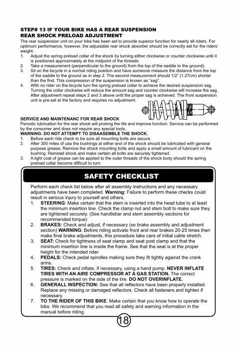
STEP# 13 IF YOUR BIKE HAS A REAR SUSPENSIONREAR SHOCK PRELOAD ADJUSTMENTThe rear suspension unit on your bike has been set to provide superior function for nearly all riders. Foroptimum performance, however, the adjustable rear shock absorber should be correctly set for the riders’weight.1. Adjust the spring preload collar of the shock by turning either clockwise or counter clockwise until it
is positioned approximately at the midpoint of the threads.2. Take a measurement (perpendicular to the ground) from the top of the saddle to the ground).3. Sit on the bicycle in a normal riding position and have someone measure the distance from the top
of the saddle to the ground as in step 2. The second measurement should 1/2” (1.27cm) shorterthan the first. This compression of the suspension is known as “sag”.
4. With no rider on the bicycle turn the spring preload collar to achieve the desired suspension sag.Turning the collar clockwise will reduce the amount sag and counter clockwise will increase the sag.After adjustment repeat steps 2 and 3 above until the proper sag is achieved. The front suspensionunit is pre-set at the factory and requires no adjustment.
SERVICE AND MAINTENANC FOR REAR SHOCKPeriodic lubrication for the rear shock will prolong the life and improve function. Service can be performedby the consumer and does not require any special tools.WARNING: DO NOT ATTEMPT TO DISAASEMBLE THE SHOCK.1. Before each ride check to be sure all mounting bolts are secure.2. After 300 miles of use the bushings at either end of the shock should be lubricated with general
purpose grease. Remove the shock mounting bolts and apply a small amount of lubricant on thebushing. Reinstall shock and make certain all bolts are securely tightened.
3. A light coat of grease can be applied to the outer threads of the shock body should the springpreload collar become difficult to turn.
Perform each check list below after all assembly instructions and any necessaryadjustments have been completed. Warning: Failure to perform these checks couldresult in serious injury to yourself and others.1. STEERING: Make certain that the stem is inserted into the head tube to at least
the minimum insertion line. Check the clamp nut and stem bolt to make sure theyare tightened securely. (See handlebar and stem assembly sections forrecommended torque)
2. BRAKES: Check and adjust, if necessary (se brake assembly and adjustmentsection) WARNING: Before riding activate front and rear brakes 20-25 times thenmake final brake adjustments, this procedure take care of initial cable stretch.
3. SEAT: Check for tightness of seat clamp and seat post clamp and that theminimum insertion line is inside the frame. See that the seat is at the properheight for the intended rider.
4. PEDALS: Check pedal spindles making sure they fit tightly against the crankarms.
5. TIRES: Check and inflate, if necessary, using a hand pump. NEVER INFLATETIRES WITH AN AIRE COMPRESSOR AT A GAS STATION. The correctpressure is marked on the side of the tire. DO NOT OVERINFLATE.
6. GENERALL INSPECTION: See that all reflectors have been properly installed.Replace any missing or damaged reflectors. Check all fasteners and tighten ifnecessary.
7. TO THE RIDER OF THIS BIKE: Make certain that you know how to operate thebike. We recommend that you read all safety and warning information in themanual before riding.
SAFETY CHECKLIST
18
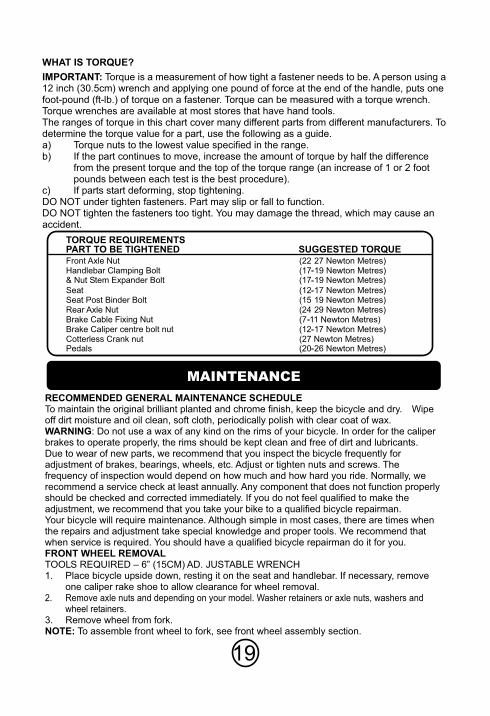
WHAT IS TORQUE?
IMPORTANT: Torque is a measurement of how tight a fastener needs to be. A person using a12 inch (30.5cm) wrench and applying one pound of force at the end of the handle, puts onefoot-pound (ft-lb.) of torque on a fastener. Torque can be measured with a torque wrench.Torque wrenches are available at most stores that have hand tools.The ranges of torque in this chart cover many different parts from different manufacturers. Todetermine the torque value for a part, use the following as a guide.a) Torque nuts to the lowest value specified in the range.b) If the part continues to move, increase the amount of torque by half the difference
from the present torque and the top of the torque range (an increase of 1 or 2 footpounds between each test is the best procedure).
c) If parts start deforming, stop tightening.DO NOT under tighten fasteners. Part may slip or fall to function.DO NOT tighten the fasteners too tight. You may damage the thread, which may cause anaccident.
TORQUE REQUIREMENTSPART TO BE TIGHTENED SUGGESTED TORQUEFront Axle Nut Handlebar Clamping Bolt
Pedals
& Nut Stem Expander Bolt
Seat Seat Post Binder BoltRear Axle Nut Brake Cable Fixing NutBrake Caliper centre bolt nutCotterless Crank nut
19
RECOMMENDED GENERAL MAINTENANCE SCHEDULETo maintain the original brilliant planted and chrome finish, keep the bicycle and dry. Wipeoff dirt moisture and oil clean, soft cloth, periodically polish with clear coat of wax.WARNING: Do not use a wax of any kind on the rims of your bicycle. In order for the caliperbrakes to operate properly, the rims should be kept clean and free of dirt and lubricants.Due to wear of new parts, we recommend that you inspect the bicycle frequently foradjustment of brakes, bearings, wheels, etc. Adjust or tighten nuts and screws. Thefrequency of inspection would depend on how much and how hard you ride. Normally, werecommend a service check at least annually. Any component that does not function properlyshould be checked and corrected immediately. If you do not feel qualified to make theadjustment, we recommend that you take your bike to a qualified bicycle repairman.Your bicycle will require maintenance. Although simple in most cases, there are times whenthe repairs and adjustment take special knowledge and proper tools. We recommend thatwhen service is required. You should have a qualified bicycle repairman do it for you.FRONT WHEEL REMOVALTOOLS REQUIRED – 6” (15CM) AD. JUSTABLE WRENCH1. Place bicycle upside down, resting it on the seat and handlebar. If necessary, remove
one caliper rake shoe to allow clearance for wheel removal.2. Remove axle nuts and depending on your model. Washer retainers or axle nuts, washers and
wheel retainers.3. Remove wheel from fork.NOTE: To assemble front wheel to fork, see front wheel assembly section.
MAINTENANCE
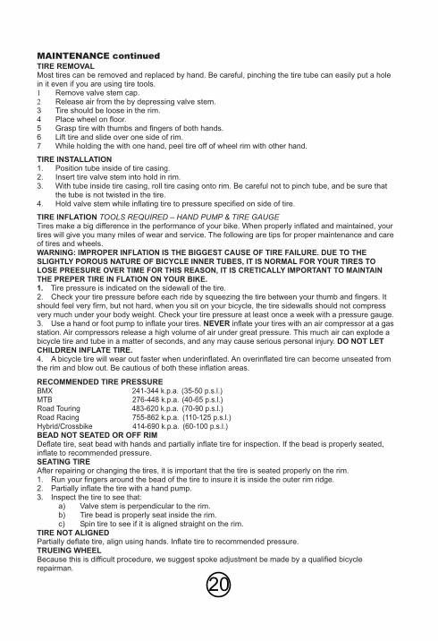
MAINTENANCE continuedTIRE REMOVALMost tires can be removed and replaced by hand. Be careful, pinching the tire tube can easily put a holein it even if you are using tire tools.1 Remove valve stem cap.2 Release air from the by depressing valve stem.3 Tire should be loose in the rim.4 Place wheel on floor.5 Grasp tire with thumbs and fingers of both hands.6 Lift tire and slide over one side of rim.7 While holding the with one hand, peel tire off of wheel rim with other hand.
TIRE INSTALLATION1. Position tube inside of tire casing.2. Insert tire valve stem into hold in rim.3. With tube inside tire casing, roll tire casing onto rim. Be careful not to pinch tube, and be sure that
the tube is not twisted in the tire.4. Hold valve stem while inflating tire to pressure specified on side of tire.
TIRE INFLATION TOOLS REQUIRED – HAND PUMP & TIRE GAUGETires make a big difference in the performance of your bike. When properly inflated and maintained, yourtires will give you many miles of wear and service. The following are tips for proper maintenance and careof tires and wheels.WARNING: IMPROPER INFLATION IS THE BIGGEST CAUSE OF TIRE FAILURE. DUE TO THESLIGHTLY POROUS NATURE OF BICYCLE INNER TUBES, IT IS NORMAL FOR YOUR TIRES TOLOSE PREESURE OVER TIME FOR THIS REASON, IT IS CRETICALLY IMPORTANT TO MAINTAINTHE PREPER TIRE IN FLATION ON YOUR BIKE.1. Tire pressure is indicated on the sidewall of the tire.2. Check your tire pressure before each ride by squeezing the tire between your thumb and fingers. Itshould feel very firm, but not hard, when you sit on your bicycle, the tire sidewalls should not compressvery much under your body weight. Check your tire pressure at least once a week with a pressure gauge.3. Use a hand or foot pump to inflate your tires. NEVER inflate your tires with an air compressor at a gasstation. Air compressors release a high volume of air under great pressure. This much air can explode abicycle tire and tube in a matter of seconds, and any may cause serious personal injury. DO NOT LETCHILDREN INFLATE TIRE.4. A bicycle tire will wear out faster when underinflated. An overinflated tire can become unseated fromthe rim and blow out. Be cautious of both these inflation areas.
RECOMMENDED TIRE PRESSUREBMX 241-344 k.p.a. (35-50 p.s.l.)MTB 276-448 k.p.a. (40-65 p.s.l.)Road Touring 483-620 k.p.a. (70-90 p.s.l.)Road Racing 755-862 k.p.a. (110-125 p.s.l.)Hybrid/Crossbike 414-690 k.p.a. (60-100 p.s.l.)BEAD NOT SEATED OR OFF RIMDeflate tire, seat bead with hands and partially inflate tire for inspection. If the bead is properly seated,inflate to recommended pressure.SEATING TIREAfter repairing or changing the tires, it is important that the tire is seated properly on the rim.1. Run your fingers around the bead of the tire to insure it is inside the outer rim ridge.2. Partially inflate the tire with a hand pump.3. Inspect the tire to see that:
a) Valve stem is perpendicular to the rim.b) Tire bead is properly seat inside the rim.c) Spin tire to see if it is aligned straight on the rim.
TIRE NOT ALIGNEDPartially deflate tire, align using hands. Inflate tire to recommended pressure.TRUEING WHEELBecause this is difficult procedure, we suggest spoke adjustment be made by a qualified bicyclerepairman.
20
Before you ride this bicycle, read the Rules For Safe Cycling and check that all parts areinstalled as per this instruction manual. It is also recommended for added safety andprotection that you wear a bicycle helmet.
If you understand how the bicycle operates, you will get the best performance. When youread this instruction book, compare the illustrations to the bicycle. Learn the location of all theparts and how they work. Keep this book for future reference.
Before you ride the bicycle, check the brake and other parts of the bike. Make sure all theparts are assembled correctly and working properly. Take your first ride in a large, open levelarea. If you have a problem, check the assembly instructions and follow the maintenanceprocedures in this book.
WARNING ON AND OFF ROAD CONDITIONS: The condition of the riding surface is veryimportant. If the surface is wet, or has sand, small rocks or other loose debris on the surface,carefully decrease the speed of the bicycle and ride with extra caution. It will also take alonger time and more distance to stop. Apply the brake earlier than normal and with lessforce to help keep the bicycle from sliding.
21
TIRE AND TUBE DAMAGETo prevent tire cuts, ruptures, rim bruise and star breaks. Avoid rough streets and alleys having glass andother debris. Don’t jump curbing. Crooked wheels cause chafing of tires as well as uneven tread wear. Toprevent distorted tire casings, hand your bicycle up or turn it upside down when storing for long periods.
BEARING ADJUSTMENT & LUBRICATIONThere are several areas on the bicycle containing bearings that must be adjusted and /or lubricated.Proper maintenance in these areas will insure longer bearing lift, and easier and safer riding. Adjustmentof the bearings requires special knowledge and tools. We strongly suggest these adjustments be madeby a qualified bicycle repairman.
FRONT FORKWARNING: IF YOU REPLACE THE FRONT FORK, MAKE SURE THE REPLACEMENT FORK HASTHE SAME RAKE AND SAME TUBE INNER DIAMETER AS THE ONE ORGINALLY FITTE TO THEBICYCLE
LUBRICATION AND CLEANINGWARNING: Do not use a vegetable base oil to lubricate bike pars. This type of oil may dry and leave aharmful gum residue.
WEEKLY: Wipe bike with a damp cloth. Wipe dry. Polish metal surfaces. On caliper brake models, do notpolish rims. Make sure no oil gets on caliper brake shoes. With a spray lubricant, lubricate chain and rearsprocket. On caliper brake models, lubricate hand brake lever cable pivot points. Wipe seat with a dampcloth and wipe dry.
ANNUALLY: The following components require lubrication, removal, disassembly, installation, specialtools and knowledge. It is suggested that this service be preformed by a qualified bicycle repairman.Caliper brake cables should be removed from housing and greased. Clean and lubricate wheel bearings,head bearings and crank bearings. Check spokes and wheels and have trued if out of line.
BRAKE RUBBER REPLACEMENTThe brake rubbers will be damaged or wom-out after long use.Loosen the anchor bolt nut and the rubber bolt nuts. Replace the damaged rubbers.Re-tighten the bolt nuts and then re-tighten the anchor bolt nut.
WARNING: Be sure the anchor bolt and the rubber bolts are fully tightened. Do not ride yourbicycle if the rubber has been damaged or has wom-out.
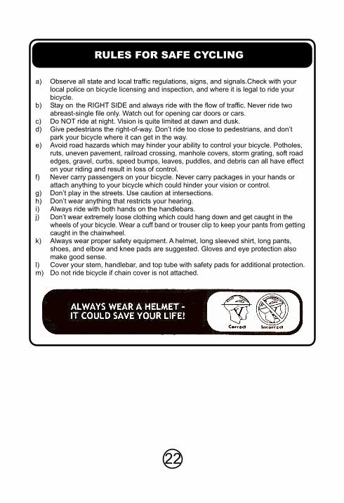
a) Observe all state and local traffic regulations, signs, and signals.Check with yourlocal police on bicycle licensing and inspection, and where it is legal to ride yourbicycle.
b) Stay on the RIGHT SIDE and always ride with the flow of traffic. Never ride twoabreast-single file only. Watch out for opening car doors or cars.
c) Do NOT ride at night. Vision is quite limited at dawn and dusk.d) Give pedestrians the right-of-way. Don’t ride too close to pedestrians, and don’t
park your bicycle where it can get in the way.e) Avoid road hazards which may hinder your ability to control your bicycle. Potholes,
ruts, uneven pavement, railroad crossing, manhole covers, storm grating, soft roadedges, gravel, curbs, speed bumps, leaves, puddles, and debris can all have effecton your riding and result in loss of control.
f) Never carry passengers on your bicycle. Never carry packages in your hands orattach anything to your bicycle which could hinder your vision or control.
g) Don’t play in the streets. Use caution at intersections.h) Don’t wear anything that restricts your hearing.i) Always ride with both hands on the handlebars.j) Don’t wear extremely loose clothing which could hang down and get caught in the
wheels of your bicycle. Wear a cuff band or trouser clip to keep your pants from gettingcaught in the chainwheel.
k) Always wear proper safety equipment. A helmet, long sleeved shirt, long pants,shoes, and elbow and knee pads are suggested. Gloves and eye protection alsomake good sense.
l) Cover your stem, handlebar, and top tube with safety pads for additional protection.m) Do not ride bicycle if chain cover is not attached.
22
RULES FOR SAFE CYCLING
REPLACED WITH FUTURE LOGISTICS DETAILS
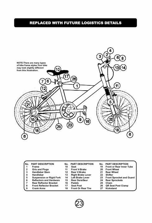
NOTE:There are many typesof bike frame styles.Your bikemay look slightly different
from this illustration.
No. PART DESCRIPTION No. PART DESCRIPTION No. PART DESCRIPTION
23

5 YEAR FRAME WARRANTY