![[Friederike Klippel] Keep Talking Communicative F(BookFi.org)](https://static.fdocuments.net/doc/165x107/56d6bfe01a28ab3016980726/friederike-klippel-keep-talking-communicative-fbookfiorg.jpg)
[Friederike Klippel] Keep Talking Communicative F(BookFi.org)
description

Loudspeakers and HeadphonesLoudspeakers and Headphonesa Tutorial on Cone Vibration and Sound Radiation Diagnosticsa Tutorial on Cone Vibration and Sound Radiation Diagnosticsgg
Wolfgang Klippel
Institute of Acoustics and Speech Communication, TU Dresden
www.klippel.de Tutorial: Cone Vibration and Radiation Diagnostics, AES London 2010, 1
p ,KLIPPEL GmbH
Our Topic TodayOur Topic Today
PERFORMANCEPERFORMANCE
70
80Total Sound Pressure Level
DESIGNDESIGN (geometry, material)(geometry, material)
conecone
0°330
300
270
240
210180°
150°
120°
90°
60°
30°
-20 -10
20
30
40
50
60
103 104
SPL
[dB]
Frequency [Hz]
Relationship ? spiderspider
Voice coilVoice coil
surroundsurround
Dust capDust cap
www.klippel.de Tutorial: Cone Vibration and Radiation Diagnostics, AES London 2010, 2
• What limits the usable frequency range ?• What causes peaks and dips in the SPL response after break-up ?• How to measure the mechanical vibration ?• Which mechanical modes are beneficial which are not ?• How to cope with vibration and radiation problems ?• How to get smooth responses, optimal directivity and low distortion ?
Simulation by Ulrik Skov Simulation by Ulrik Skov

Measurements Measurements for assessing small signal performancefor assessing small signal performance
Distance > 1 mDistance > 1 mDistance Distance ≈≈ 1 cm1 cmstimulusstimulus
Electrical Measurement
AcousticalMeasurement
60
70
80Total Sound Pressure Level
dB]
www.klippel.de Tutorial: Cone Vibration and Radiation Diagnostics, AES London 2010, 3
Far Field SPL Response
Distributed Parameters acousticalacoustical
0°330
300
270
240
210180°
150°
120°
90°
60°
30°
-20 -10
20
30
40
50
103 104
SP
L [d
Frequency [Hz]
Lumped Parameters electricalelectrical
ImpedanceZe(f)=U(f)/I(f)
KLIPPEL
3
4
5
6
7
8
9
10
11
12
13
14
15
101 102 103
magnitude of electric impedance Z(f)
[Ohm
]
f [Hz]
measured estimated
Loudspeaker ModelLoudspeaker Model
Distance > 1 mDistance > 1 m
Distance Distance ≈≈ 1 cm1 cmstimulusstimulusVibrationMotor Radiation
F X(r) soundfield
near far
60
70
80Total Sound Pressure Level
dB]
AcousticalMeasurement
VibrationMotor Radiation
V F(r)u field field
Electrical Measurement
www.klippel.de Tutorial: Cone Vibration and Radiation Diagnostics, AES London 2010, 4
0°330
300
270
240
210180°
150°
120°
90°
60°
30°
-20 -10
20
30
40
50
103 104
SP
L [d
Frequency [Hz] Far Field SPL Response
Distributed Parameters acousticalacoustical
ImpedanceZe(f)=U(f)/I(f)
Lumped Parameters electricalelectrical
KLIPPEL
3
4
5
6
7
8
9
10
11
12
13
14
15
101 102 103
magnitude of electric impedance Z(f)
[Ohm
]
f [Hz]
measured estimated

More Comprehensive AssessmentMore Comprehensive Assessment
VibrationMotor Radiation
F X(r) soundfield
near farVoice Cone‘s VibrationMotor Radiation
V F(r)u field fieldcoil surface
Electrical Measurement
Mechanical Measurement
AcousticalMeasurement
www.klippel.de Tutorial: Cone Vibration and Radiation Diagnostics, AES London 2010, 5
Lumped Parameters Distributed Parameters electricalelectrical
Hx(f)=X(f)/U(f)
mechanicalmechanical
Cone Vibration+ Geometry
mechanicalmechanical acousticalacoustical
Far Field SPL Response
ImpedanceZe(f)=U(f)/I(f)
Cone Scanning TechniquesCone Scanning Techniques
Amplitude+ phase Amplitude Amplitude + phase + geometry
Doppler Interferometry Doppler Interferometry (Polytech, 1995)(Polytech, 1995)
Triangulation Laser Scanner Triangulation Laser Scanner (Klippel, 2007)(Klippel, 2007)
geometry
Cladni FiguresCladni Figures(Cladni, 1787(Cladni, 1787
Corrington 1951)Corrington 1951)
www.klippel.de Tutorial: Cone Vibration and Radiation Diagnostics, AES London 2010, 6
Laser Intensity InterferometryLaser Intensity Interferometry(Frankort 1978)(Frankort 1978)
geometry
displacementVelocity destribution on the cone
intensity

Diagnostics on Cone Vibration and Radiation Diagnostics on Cone Vibration and Radiation
Sound Pressure•of total vibration •of separated components•on-axis
Improvements, New design choices
Drive Unit(woofer, tweeter, ...)
Geometryzzcc((ϕϕ,r,rcc))
VibrationHH ((jj rr ))
Acceleration(accumulated level)
Sound Power•of separated components •directivity index•coverage angle
on axis•Directivity (polar plot)
Vibration &RadiationAnalysis
3937,5 Hz
Selection of optimal drive
www.klippel.de Tutorial: Cone Vibration and Radiation Diagnostics, AES London 2010, 7
HHcc((jjωω,,ϕϕ,r,rcc)) •of total vibration•of separated components
•Components•modal analysis•radial/circumferential•contribution to SPL output•irregularities
optimal drive unit for loudspeaker system design
Prediction of Sound Pressure in the Far FieldPrediction of Sound Pressure in the Far Fieldusing Distributed Mechanical Parameters from Laser Scanningusing Distributed Mechanical Parameters from Laser Scanning
Rayleigh Integral Equation
jX )(2
• Fast prediction of sound pressure
• Based on measured geometry and
crrjk
S ca
ca dSe
rrrjXrjp ca
c
−−
∫ −=
),(2
),( 02 ωπρωω
( )dB
p
rjprSPL
o
aa
=
,log20),(
ωω
www.klippel.de Tutorial: Cone Vibration and Radiation Diagnostics, AES London 2010, 8
• Based on measured geometry anddisplacement x in z-direction
• Sufficiently accurate for shallow cones
• Could be improved by BEA

Practical ExamplesPractical Examplessee W. Klippel, et.al., “ Distributed Mechanical Parameters of Loudspeakers, Journal see W. Klippel, et.al., “ Distributed Mechanical Parameters of Loudspeakers, Journal
AES, Vol. 57, No. 7/8,9, 2009AES, Vol. 57, No. 7/8,9, 2009
Woofer A with paper cone
Woofer B with magnesium cone
www.klippel.de Tutorial: Cone Vibration and Radiation Diagnostics, AES London 2010, 9
Woofer C with flat radiator
Smooth SPL Response ?Smooth SPL Response ?
Woofer A with paper cone
KLIPPEL
50
55
60
65
70
75
80
SPL
[dB] -30 degree
on -axis
+30 degree
40
45
102 103f [Hz]
Woofer B with magnesium cone
KLIPPEL
20
30
40
50
60
70
80
90
102 103 104
SPL
[dB]
f [Hz]
-30 degree
on -axis
+30 degree
www.klippel.de Tutorial: Cone Vibration and Radiation Diagnostics, AES London 2010, 10
Woofer C with flat radiator
KLIPPEL
20
30
40
50
60
70
80
102 103 104
-30 degree
on -axis
+30 degree

How to How to AAssess ssess TTotal otal CCone one VVibration ? ibration ?
),( crjX ω
Potential energydepends on bending
Kinetic Energydepends on
www.klippel.de Tutorial: Cone Vibration and Radiation Diagnostics, AES London 2010, 11
However, thickness of cone, Young‘s E Modulus, density are not known and can not be measured by laser scanner !!
p gstiffness
pmoving mass
Total mechanical energyNot practical !
Accumulated Acceleration LevelAccumulated Acceleration Level1078,1 Hz
),( crjX ω Weighted Sum of the absolute value of cone
l ti
KLIPPEL
80
90Acceleration Level
cS ca
caa dS
rr
rjXrja
c
∫ −=
),(
2),( 0
2 ω
πρωω
acceleration
),( crjX ω
Very similar to Rayleigh Integral for SPL prediction !!
www.klippel.de Tutorial: Cone Vibration and Radiation Diagnostics, AES London 2010, 12
Rigid body modes
30
40
50
60
70
80
100 1000 10000
ALL
[dB]
f [Hz]
dBprja
rAALo
aqa
=
),(log20),(
ωω
Reference sound pressure p0

Accumulated Acceleration Level (AAL)Accumulated Acceleration Level (AAL)
Acceleration levelKLIPPEL
70
80
90
Acceleration Level
Total sound Pressure levelRigid body modes
30
40
50
60
70
100 1000 10000
SPL
[dB]
f [Hz]
Total SPLRigid body modes
INTERPRETATION:
www.klippel.de Tutorial: Cone Vibration and Radiation Diagnostics, AES London 2010, 13
• AAL is comparable with SPL • AAL is identical with SPL for a rigid body mode• AAL is never smaller than SPL• AAL neglects acoustical cancellation• AAL has significantly less dips
• AAL describes total mechanical vibration
Sufficient Cone Vibration ?Sufficient Cone Vibration ?KLIPPEL
60
65
70
75
80
SP
L [d
B] Total SPL
acceleration level
Woofer A with paper cone:low Q factor of cone resonances
Compare SPL and AAL !
50
55
60
102 103f [Hz]
AAL is 5-8 dB higher than SPL
KLIPPEL
50
55
60
65
70
75
80
85
90
SPL
[dB]
Total SPL
acceleration level Woofer B with magnesium cone:natural modes cause high peaks in SPLAAL is 5-10 dB higher than SPL
www.klippel.de Tutorial: Cone Vibration and Radiation Diagnostics, AES London 2010, 14
102 103 104f [Hz]
KLIPPEL
30
40
50
60
70
80
90
102 103 104
SP
L [d
B]
f [Hz]
Total SPL
acceleration level
Woofer C with flat radiatordips are not visible in AALAAL cause peak at 0.8 kHzAAL is 10 – 30 dB higher than SPL

KLIPPEL90
Acceleration Level
Modal AnalysisModal AnalysisExpansion into a Series of Orthogonal ModesExpansion into a Series of Orthogonal Modes
::Accumulated Acceleration:Accumulated Acceleration:
30
40
50
60
70
80
100 1000 10000
SPL
[dB]
f [Hz]
Acceleration Level
Natural Functions describing mode shape
Frequency response for each mode
( )∑∞
=
=0
)(i
ii jHaja ωω
( )∑∞
=
=0
)(),(i
ciic rjHrjX ψωω
Displacement:Displacement:
www.klippel.de Tutorial: Cone Vibration and Radiation Diagnostics, AES London 2010, 15
NaturalNaturalFunctionFunction
NaturalNaturalfrequenciesfrequencies 840 Hz840 Hz 3,8 kHz3,8 kHz 8,1 kHz8,1 kHz70 Hz70 Hz 11,2 kHz11,2 kHz
Completely different mode shapes (orthogonal) !Completely different mode shapes (orthogonal) !
Frequency Response of a Single ModeFrequency Response of a Single ModeNatural Functions
www.klippel.de Tutorial: Cone Vibration and Radiation Diagnostics, AES London 2010, 16
Loss factor( )∑
∞
=
=0
)(),(i
ciic rjHrjX ψωω
Frequency response Natural Frequency
ωi
( ) ( )2//11
iiii
jjH
ωωωωηω
−+=

How to Specify the Radiator How to Specify the Radiator Cone, Diaphragm and SurroundCone, Diaphragm and Surround
KLIPPEL
70
80
90
Acceleration Level
Natural Functions
Total sound Pressure levelRigid body modes
30
40
50
60
70
100 1000 10000
SPL
[dB]
f [Hz]
Modal loss factor ηi of each mode ith-mode with
Natural frequency fi of the ith-mode with i 1 2
Natural Function Ψi (rc)of each mode ith-mode with i=1 2
www.klippel.de Tutorial: Cone Vibration and Radiation Diagnostics, AES London 2010, 17
i=1,2,... i=1,2,...
Geometry of the Radiator (shape, thickness, ..)
Young‘s E Modulus of the material
Loss factor of the material
i=1,2,...
92,5AAL [dB]
Sufficient Damping of the Material ?Sufficient Damping of the Material ?
3dB
0 dB
Read the bandwidth for 3dB decay in the accumulated acceleration level !!
Acceleration Level
77,5
80,0
82,5
85,0
87,5
6*102 7*102 8*102 9*102 103
f [Hz]
- 3dB
fI- fI+fi
www.klippel.de Tutorial: Cone Vibration and Radiation Diagnostics, AES London 2010, 18
i
iii f
ff −+ −=η
• Modal Loss Factor depends on frequency and temperature• describes the material used (independent of the geometry)• multiple parts (cone, surround, spider) may contribute to the modal loss factor

Where to apply additional damping ?Where to apply additional damping ?Woofer C with flat radiatorWoofer C with flat radiator
90
Total Acceleration Level
820,3 Hz 12398,4 Hz
65
70
75
80
85
90
102 103 104
AC
C [d
B]
Frequency [Hz]View the shape of the modes !
www.klippel.de Tutorial: Cone Vibration and Radiation Diagnostics, AES London 2010, 19
Find places of high deformation !
Where to apply additional damping ?Where to apply additional damping ?Woofer B Magnesium coneWoofer B Magnesium cone
KLIPPEL
85
90
50
55
60
65
70
75
80
85
100 1000 10000
AAL
[dB]
f [Hz]
Acceleration Level
10 >η 5.01 =η 01.02 <η
0ω
www.klippel.de Tutorial: Cone Vibration and Radiation Diagnostics, AES London 2010, 20
11109,4 Hz
Rubber surround has sufficient losses Magnesium requires damping

What Causes the Dips What Causes the Dips in the SPL Response of Woofer C ?in the SPL Response of Woofer C ?
1078,1 Hz q2
KLIPPEL
80
90
acceleration level q2
q130
40
50
60
70
102 103 104
SP
L [d
B]
f [Hz]
Total SPL
Significant difference between AAL and SPL !
www.klippel.de Tutorial: Cone Vibration and Radiation Diagnostics, AES London 2010, 21
PROBLEM: • There is sufficient mechanical vibration (no dip in AAL)• Node devides radiator in two areas each producing the same volume velocity in opposite phase
Acoustical cancellation q1+ q2=0
SoundSound--PressurePressure--Related DecompositionRelated Decomposition
Total displacement of Total displacement of woofer C at 1.4 kHzwoofer C at 1.4 kHz
generates sound Reduces sound no sound
ofoutantiintotal xxxx −++= quadrature
www.klippel.de Tutorial: Cone Vibration and Radiation Diagnostics, AES London 2010, 22
SPL ComponentsSPL ComponentsKLIPPEL
70
80
Total SPLIn-Phase Component
0
10
20
30
40
50
60
102 103
SPL
[dB]
f [Hz]
Anti-Phase ComponentRigid body mode
Quadrature component
www.klippel.de Tutorial: Cone Vibration and Radiation Diagnostics, AES London 2010, 23
f [Hz]
•In-phase component produces the highest SPL•Anti-phase component generates a small SPL below break-up•Quadrature component generates no SPL
r
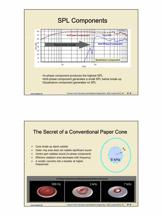
The Secret of a Conventional Paper ConeThe Secret of a Conventional Paper Cone
rbrbrb• Cone break-up starts outside
O t i d t di t i ifi t d
1 kHz
rb
2 kHz
rb
4 kHz
rb
6 kHz
rb• Outer ring area does not radiate significant sound • Centre part radiates sound (in-phase component)• Effective radiation area decreases with frequency• A woofer converts into a tweeter at higher
frequencies
www.klippel.de Tutorial: Cone Vibration and Radiation Diagnostics, AES London 2010, 24
500 Hz 3 kHz 7 kHz
InIn--Phase Component contributing constructively to the soundPhase Component contributing constructively to the sound

Acoustical CancellationAcoustical CancellationKLIPPEL
80
90
0
10
20
30
40
50
60
70
80
2*102 4*102 6*102 8*102 103 2*103 4*103 6*103 8*103
SPL
[dB]
Total SPLIn-Phase Component
Anti-Phase Component
www.klippel.de Tutorial: Cone Vibration and Radiation Diagnostics, AES London 2010, 25
2 10 4 10 6 10 8 10 10 2 10 4 10 6 10 8 10f [Hz]
If the in-phase component equals the SPL of anti-phase component then a dip in the total SPL response is generated !!
Total Vibration Component
Components change the position at a Components change the position at a cancellation frequency cancellation frequency
Anti-Phase Component
anti-phase component
www.klippel.de Tutorial: Cone Vibration and Radiation Diagnostics, AES London 2010, 26
In-Phase Component
In-phase component

How to Avoid Dips in the Total SPL Response ?How to Avoid Dips in the Total SPL Response ?
KLIPPEL65 In-phase
2530354045
dB 5560
In phase
anti-phasetotal-phase
Keep anti-phase component 10 dB
www.klippel.de Tutorial: Cone Vibration and Radiation Diagnostics, AES London 2010, 27
10152025
200 1000 200 800Frequency [Hz]
Keep anti phase component 10 dB below in-phase component
Where is the sound radiated Where is the sound radiated in paper cone of Woofer A ?in paper cone of Woofer A ?
In phase component is dominant
KLIPPEL
70
80
In-Phase Component • In-phase component is dominant• No acoustical cancellation• In-phase component stays in the centre • radiation area shrinks with frequency
0
10
20
30
40
50
60
102 103
SPL
[dB]
f [Hz]
In-Phase Component
Anti-Phase Component
www.klippel.de Tutorial: Cone Vibration and Radiation Diagnostics, AES London 2010, 28
0.1 kHz 1 kHz0.7 kHz 10 kHz4 kHz1 kHz
In-Phase Component

Gradual BreakGradual Break--up of the Paper Coneup of the Paper Cone
qq3
q4
q1 is dominant and generates a dominant in-phase
Volumevelocity
q2
High bending stiffnesLow bendingstiffness
q1
www.klippel.de Tutorial: Cone Vibration and Radiation Diagnostics, AES London 2010, 29
pcomponent
frequency
Where is the sound radiated Where is the sound radiated in Woofer B: Magnesium Cone ?in Woofer B: Magnesium Cone ?
KLIPPEL
80
85
90
S
In-Phase Component Anti-Phase Component
• In-phase component is dominant
40
45
50
55
60
65
70
75
80
103 104
dB
- [V
] (
rms)
Frequency [Hz]
p p• No acoustical cancellation• In-phase component stays in the centre • radiation area shrinks with frequency
www.klippel.de Tutorial: Cone Vibration and Radiation Diagnostics, AES London 2010, 30
20 kHz12 kHz 15 kHz10 kHz7.5 kHz3 kHzIn-Phase Components

KLIPPEL
859095
(rm
s)
In-Phase Component Anti-Phase Component
Dominant InDominant In--Phase Component ? Phase Component ? Woofer C with flat radiatorWoofer C with flat radiator
Cancellation frequencies Check difference !
556065707580
103 104
dB
- [V
] (
Frequency [Hz]
in-phase
anti-phase
www.klippel.de Tutorial: Cone Vibration and Radiation Diagnostics, AES London 2010, 31
Localization of the in-phase component
•There is no dominant in-phase component which produces sound • Anti-phase component becomes equal to in-phase component• In-phase and anti-phase components change their location
How to Fix Acoustical Cancellation Problems ?How to Fix Acoustical Cancellation Problems ?
Area of in-phase component
INCREASE
o onode
Target: • Make in-phase component dominant• Suppress anti-phase component
www.klippel.de Tutorial: Cone Vibration and Radiation Diagnostics, AES London 2010, 32
Steps: 1. find location of in-phase component2. use FEA to simulate behavior3. increase bending stiffness at this area (thickness, curvature, rips)

Radiation into 3D SpaceRadiation into 3D Space
φ
9090oo
9090oo
ro
ϕ
--9090oo
--9090oo
180180oo
9090
Simulation by Ulrik Skov Simulation by Ulrik Skov
www.klippel.de Tutorial: Cone Vibration and Radiation Diagnostics, AES London 2010, 33
Pressure at the reference pointPressure at the reference point
Voltage at the terminalsVoltage at the terminals @ r@ r00= 1m and U= 1m and Uoo=2.83 V=2.83 V
SensitivitySensitivity
dBp
UrjHfLp
=
0
0010
),,,(log20),,(
φϕωφϕ
)(),,,(
),,,( 00 ω
φϕωφϕω
UrP
rjH =
Transfer Response H(jTransfer Response H(jωω,,ϕϕ,,φφ,r,roo))
Important Responses Describing Acoustical OutputImportant Responses Describing Acoustical Output
On-axisResponse
)0,0,()( fLfL pon =
ListeningWindow
Response
ϕ =0, ±10° , ±20° , ±30°φφ = = ±10°
∑=
=9
1
),,(91)(i
iiplW fLfL φϕ
EarlyReflectionResponse
ϕ =0, ±10° , ±20° , ±30° , ±40° , ±50° ±60° ±70° ±80° ±90° ±1800°
∑=
=I
iiiper fL
IfL
1
),,(1)( φϕ
Toole, 2007Toole, 2007SoundPower
Response
∫=ΠS
dSUrjHc
f 20
20 ),,,(1)( φϕω
ρ
Π
=)(log10)( ffL
www.klippel.de Tutorial: Cone Vibration and Radiation Diagnostics, AES London 2010, 34
φφ = = ±10 , ±60 , ±70 , ±80 , ±90 , ±1800φφ= = −−20°, −30°,− 40°, 40°, 50°, 60°
=Π0
10log10)(P
fL
With PWith P00=10=10--1212 WW
∫=
S
dSrjH
SrjHD2
0
20
),,,(
),0,0,(
φϕω
ω
Directivity
Directivity IndexDDI 10log10=

Sound Pressure SPL @ 1m, 1V Accumulated Acceleration (AAL)
Power Level +47 dB @ 1V
Three Important ResponsesThree Important Responses
KLIPPEL
60
70
80
90
100
AAL
Maximal possible sound pressure output
Acousticalcancellation
www.klippel.de Tutorial: Cone Vibration and Radiation Diagnostics, AES London 2010, 35
50
60
101 102 103 Power
On-axis
Example: woofer
Piston mode
DirectivityIndex
Displacement is inDisplacement is in--phasephaseOmniOmni--directional behaviordirectional behavior(like a point source)(like a point source)
Desired Directivity Index ?Desired Directivity Index ?
KLIPPEL
65
70
75
80
er
[dB
]
Sound Power Level SPL on-axis
power
SPL on-axis
KLIPPEL
-20
-10
0
10
20
30
Magnesium Cone
Flat Piston
Paper Cone40
45
50
55
60
102 103
Pow
e
f [Hz]
Woofer A with paper cone
KLIPPEL
45
50
55
60
65
70
75
80
85
90
Pow
er
[dB
]
Sound Power Level SPL on-axis
Woofer B with magnesium conepower
SPL on-axis
OmniOmni--directionaldirectional
www.klippel.de Tutorial: Cone Vibration and Radiation Diagnostics, AES London 2010, 36
-30
102 103 104
40
45
102 103 104
f [Hz]
KLIPPEL
30
35
40
45
50
55
60
65
70
75
80
85
90
102 103 104
Pow
er [
dB
]
f [Hz]
Sound Power Level SPL on-axis
Woofer C with flat radiator power
SPL on-axis

Directivity Pattern in the Piston ModeDirectivity Pattern in the Piston Modera
Rayleigh Integral Equationcrrjkc
a dSerjXrjp ca −−
∫=),(
2),( 0
2 ωρωω
rc,1
rc,2Cone vibrates as a rigid Cone vibrates as a rigid bodybody
www.klippel.de Tutorial: Cone Vibration and Radiation Diagnostics, AES London 2010, 37
cS ca
arr
jpc
∫ −2)(
π
Phase shift generating by the difference in the distance between particular source point rc and reference point ra
Transition Frequency Transition Frequency ftfor a rigid pistonfor a rigid piston
0°330 30°
Polar plot
r
o
ot r
cfπ7.0
=
330
300
270
240
210180°
150°
120°
90°
60°
30
-15 -10 -5ro
r
r1
|r-r1|
r2
|r-r2|
λ/2
www.klippel.de Tutorial: Cone Vibration and Radiation Diagnostics, AES London 2010, 38
• At f= ft sound wavelength λ in air is approximately equal to the piston circumference
• At f > ft Sound power response decreases by 6 dB/oct.directivity index increases by 6 dB/oct. the beam becomes more directive

Cone CutCone Cut--off Frequency off Frequency fcfor rigid conefor rigid cone
cHH
Hcf o
c π=λ/2
0°330
300 60°
30°
Polar plot
www.klippel.de Tutorial: Cone Vibration and Radiation Diagnostics, AES London 2010, 39
f > fc many sound waves fit between cone top and base
attenuation on-axisgeneration of side lobes
270
240
210180°
150°
120°
90°-15 -10 -5
Rigid Piston and ConeRigid Piston and Cone
Sound Power
Lπ
Sound Pressure in axisLP
conecone
piston piston
www.klippel.de Tutorial: Cone Vibration and Radiation Diagnostics, AES London 2010, 40
fc fcft ft
ft transition frequency (above which piston has higher directivity)
fc cut-off frequency wavelength λ> 3H (cone height H)
ff

Directivity Pattern after BreakDirectivity Pattern after Break--upup
1078,1 Hz
ra
Rayleigh Integral Equationcrrjkc
a dSerjXrjp ca −−
∫=),(
2),( 0
2 ωρωω
rc,1
rc,2
Out of phase
www.klippel.de Tutorial: Cone Vibration and Radiation Diagnostics, AES London 2010, 41
cS ca
arr
jpc
∫ −2)(
π
2. Phase difference in the mechanical cone vibration of different source points rc
1. Phase shift generating by the difference in the distance between particular source point rc and reference point ra
Distance compensates for Phase of DisplacementDistance compensates for Phase of Displacement
0°
330
300 60°
30°
InIn--Phase Component Phase Component radiating the sound in 60 radiating the sound in 60 degree offdegree off--axis (woofer C)axis (woofer C)
www.klippel.de Tutorial: Cone Vibration and Radiation Diagnostics, AES London 2010, 42
270
240
210
180°
150°
120°
90°-15 -10 -5
Both geometry and vibration determine the directivity pattern !! Both geometry and vibration determine the directivity pattern !!

Headphone Headphone –– Vibration 2760 HzVibration 2760 Hz
www.klippel.de Tutorial: Cone Vibration and Radiation Diagnostics, AES London 2010, 43
Headphone Headphone –– Radiation 2760 HzRadiation 2760 Hz
0°
330
300 60°
30°
ϕTwo Circumferential Two Circumferential modes with modes with opposite phaseopposite phase
80Total Sound Pressure Level
270
240
210
180°
150°
120°
90°-15 -10 -5
opposite phase opposite phase cause a beam cause a beam steering offsteering off--axisaxis + - + -
dipoledipole dipoledipole
www.klippel.de Tutorial: Cone Vibration and Radiation Diagnostics, AES London 2010, 44
20
30
40
50
60
70
103 104
SP
L [d
B]
Frequency [Hz]

How to Separate Circumferential Modes ?How to Separate Circumferential Modes ?
xxx +=
Decomposition technique for raditors with axialDecomposition technique for raditors with axial--symmetrical geometry:symmetrical geometry:
Total vibration mode
Circumferential vibration mode
circradtotal xxx +=
Radial vibration mode
Averaging over circumference radtotalcirc xxx −=
www.klippel.de Tutorial: Cone Vibration and Radiation Diagnostics, AES London 2010, 45
HigherHigher--order Circumferential Modesorder Circumferential ModesWoofer C with flat radiatorWoofer C with flat radiator
KLIPPEL90
Accumulated Acceleration Level
Total AAL Radial AAL Circumferential AAL
www.klippel.de Tutorial: Cone Vibration and Radiation Diagnostics, AES London 2010, 46
Above 4 kHz the AAL of the Above 4 kHz the AAL of the circumferential mode becomes circumferential mode becomes
comparable with the radial comparable with the radial componentcomponent
How much sound is generated How much sound is generated by the circumferential modes ? by the circumferential modes ?
50
55
60
65
70
75
80
85
90
102 103 104
SP
L [dB
]
f [Hz]

KLIPPEL
80
90
Total SPL
SPL Generated by Circumferential ModesSPL Generated by Circumferential Modesonon--axis response of woofer C axis response of woofer C
20
30
40
50
60
70
80
SPL
[dB]
Total SPL
Circular Component (Acceleration)
Circ lar Component (SPL)
on-axis
www.klippel.de Tutorial: Cone Vibration and Radiation Diagnostics, AES London 2010, 47
0
10
102 103 104
f [Hz]
Circular Component (SPL)
Circumferential component produces very low output on-axis
KLIPPEL
80
90
Total SPL
Sound Radiated in Other Directions ? Sound Radiated in Other Directions ?
20
30
40
50
60
70
SPL
[dB]
Circular Component (Acceleration)
Circular Component (SPL)
off-axis
www.klippel.de Tutorial: Cone Vibration and Radiation Diagnostics, AES London 2010, 48
10
102 103 104
f [Hz]
Circular component contibutes significantly to 60 degree off-axis

Power Generated by Circumferential ModesPower Generated by Circumferential Modeswoofer C Flat Pistonwoofer C Flat Piston
KLIPPEL90
power
KLIPPEL
50
60
70
80
Pow
er [d
B]
Total Power
Total AAL
Circular Component (Sound Power)
www.klippel.de Tutorial: Cone Vibration and Radiation Diagnostics, AES London 2010, 49
20
30
40
102 103 104
f [Hz]
How to Find Circumferential Modes How to Find Circumferential Modes on Radiators with Nonon Radiators with Non--axially Symmetrical Shape (e.g. Oval Speaker) ?axially Symmetrical Shape (e.g. Oval Speaker) ?
Cancellation effect in SPL on axis t i i d t
OnOn--axisaxis
TotalTotal KLIPPEL
65
70
Acceleration Level
Total Component Quadrature AccelerationQuadratureQuadrature
generates maxima in quadrature component of AAL (sound pressure related decomposition)
www.klippel.de Tutorial: Cone Vibration and Radiation Diagnostics, AES London 2010, 50
20
25
30
35
40
45
50
55
60
103 104
SP
L [d
B]
f [Hz]
1.3 kHz1.3 kHz

Is the Rocking Mode Too High ?Is the Rocking Mode Too High ?Woofer A with paper coneWoofer A with paper cone
Rocking is negliglible if d t t
60
70
80 Total AAL
-20 dB
voice coil rubbing
www.klippel.de Tutorial: Cone Vibration and Radiation Diagnostics, AES London 2010, 51
quadrature component is 20 dB below total component !
0
10
20
30
40
50
100 1000
[dB]
f [Hz]
Quadrature Component (AAL)
Anisotropy of the Cone MaterialAnisotropy of the Cone MaterialMidrange with KevlarMidrange with Kevlar
Fibrestructure
phase7 kHz7 kHz
www.klippel.de Tutorial: Cone Vibration and Radiation Diagnostics, AES London 2010, 52
amplitude

Nonlinear DistortionNonlinear Distortiongenerated bygenerated by significant deformation of the geometry
Shell segment σstress
High local displacementHigh local displacement
b
ξ
b<<ξstretch
ε
plastic deformation
www.klippel.de Tutorial: Cone Vibration and Radiation Diagnostics, AES London 2010, 53
18 inch wooferCompression driver
Influence of the Air Load Influence of the Air Load ??example headphone transducerexample headphone transducer
KLIPPEL
60
70
80
B] SPL free air
SPL vacuum
••Perform scans in air Perform scans in air
30
40
50
103 104
SP
L [d
B
f [Hz]
SPL free air
in airin air
3.8 kHz
and in vacuumand in vacuum••Compare mechanical Compare mechanical vibration (AAL) or vibration (AAL) or predicted sound predicted sound pressure output (SPL)pressure output (SPL)
in vacuumin vacuum
www.klippel.de Tutorial: Cone Vibration and Radiation Diagnostics, AES London 2010, 54

How to Optimize the Design ?How to Optimize the Design ?Coupled mechano-acoustical analysis
FEA BEAMagnetic
FEA
Mechanical System
(suspension,cone,
diaphragm)
Motor(coil,gap,
magnet)
Acoustical System
(enclosure,horn)
F X(rc)
F(rc)Far-Field
u Sound Propagation p(ra)
p(r)
v(r)
Pv
Tv
coilformer Radiator near field
FEAFEA
www.klippel.de Tutorial: Cone Vibration and Radiation Diagnostics, AES London 2010, 55
ThermalDynamics
Thermal
FEA
Providing Input Data for FEAProviding Input Data for FEARadiator
(cone, diaphragm, panel)
Material
E,ηFiniteElement
Drive Unit
MaterialParametersAnalysis
Predicted Víbration(accumulated level + shape)•of total vibration•of separated components
3937,5 Hz
Modal & DecompositionAnalysis
η
www.klippel.de Tutorial: Cone Vibration and Radiation Diagnostics, AES London 2010, 56
Drive Unit(woofer, tweeter, ...)
Geometry
Vibration
Measured Víbration(accumulated level + shape)•of total vibration•of separated components
3937,5 Hz
Modal & DecompositionAnalysis
AnalysisFitting

FEA Tools for Cone Design FEA Tools for Cone Design Progress:
• Processing time, handlingFineConeFineCone
By P. LarsenBy P. Larsen
by A. Svobodnikby A. SvobodnikNADworkNADwork
ocess g t e, a d g
• Asymmetries in the shape
• Geometrical nonlinearities (“variation of the geometry”)
• Acoustical-mechanical coupling
Problems:
www.klippel.de Tutorial: Cone Vibration and Radiation Diagnostics, AES London 2010, 57
ANSYSANSYS
ComsolComsol
• (Nonlinear) Material parameters
• visco-elastic properties (Hyperelasticity, creep, Relaxation)
PacsysPacsys
Optimal Design of the EnclosureOptimal Design of the Enclosure
Acoustical
Sound Pressure•on-axis•directivity
Drive Unit(woofer, tweeter, ...)
Geometry
enclosure,horn room
System(enclosure, horn, room)
Geometry
BEA+
FEA
Geometry
Vibration Sound Power
AdmittanceY(jω) at voice coil
3937,5 Hz
Linear Linear Lumped & Lumped & Distributed Distributed ParametersParameters
www.klippel.de Tutorial: Cone Vibration and Radiation Diagnostics, AES London 2010, 58
horn, roomGeometry
Velocity in the portVelocity in the port
Air NoiseAir Noise
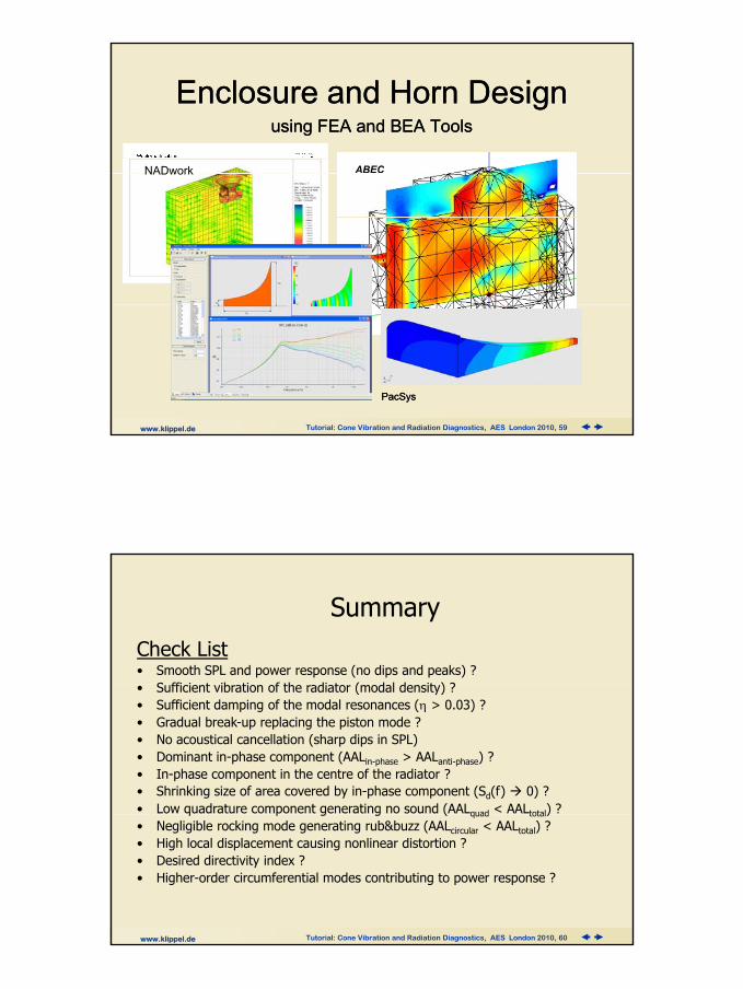
Enclosure Enclosure and Horn and Horn DesignDesignusing FEA and BEA Toolsusing FEA and BEA Tools
NADwork ABECNADwork
www.klippel.de Tutorial: Cone Vibration and Radiation Diagnostics, AES London 2010, 59
PacSysPacSys
SummaryCheck List • Smooth SPL and power response (no dips and peaks) ?
S ffi i t ib ti f th di t ( d l d it ) ?• Sufficient vibration of the radiator (modal density) ?• Sufficient damping of the modal resonances (η > 0.03) ? • Gradual break-up replacing the piston mode ? • No acoustical cancellation (sharp dips in SPL)• Dominant in-phase component (AALin-phase > AALanti-phase) ?• In-phase component in the centre of the radiator ?• Shrinking size of area covered by in-phase component (Sd(f) 0) ? • Low quadrature component generating no sound (AALquad < AALtotal) ?
www.klippel.de Tutorial: Cone Vibration and Radiation Diagnostics, AES London 2010, 60
q p g g ( quad total)• Negligible rocking mode generating rub&buzz (AALcircular < AALtotal) ?• High local displacement causing nonlinear distortion ?• Desired directivity index ?• Higher-order circumferential modes contributing to power response ?
Many thanks !Many thanks !
Get a CD with the Analysis Software Get a CD with the Analysis Software
More detailed information please find in :More detailed information please find in :
W. Klippel, J. Schlechter, “Distributed Mechanical Parameters of LoudspeakersW. Klippel, J. Schlechter, “Distributed Mechanical Parameters of Loudspeakers Part 1:Part 1:
www.klippel.de Tutorial: Cone Vibration and Radiation Diagnostics, AES London 2010, 61
W. Klippel, J. Schlechter, Distributed Mechanical Parameters of Loudspeakers W. Klippel, J. Schlechter, Distributed Mechanical Parameters of Loudspeakers Part 1: Part 1: Measurement,“ J. Audio Eng. Society 57, No. 7/8, pp. 501 Measurement,“ J. Audio Eng. Society 57, No. 7/8, pp. 501 –– 511.511.
W. Klippel, J. Schlechter, “Distributed Mechanical Parameters of Loudspeakers W. Klippel, J. Schlechter, “Distributed Mechanical Parameters of Loudspeakers Part 2: Part 2: Diagnostics,“ J. Audio Eng. Society 57, No. 9, Diagnostics,“ J. Audio Eng. Society 57, No. 9,
Further ReferencesFurther References
F.J. M Frankort, „Vibration Patterns and Radiation Behavior of Loudspeaker Cones,“ J. of F.J. M Frankort, „Vibration Patterns and Radiation Behavior of Loudspeaker Cones,“ J. of Audio Eng. Soc., Sept. 1978, Vol.l 26. Pp. 609Audio Eng. Soc., Sept. 1978, Vol.l 26. Pp. 609--622622
Kaizer, A., “Calculation of the Sound Radiation of a Nonrigid Loudspeaker Diaphragm Kaizer, A., “Calculation of the Sound Radiation of a Nonrigid Loudspeaker Diaphragm Using the FiniteUsing the Finite--Element Method,”Element Method,” J. of Audio Eng. SocJ. of Audio Eng. Soc., ,Vol. 36 ,Nr. 7/8, pp. 539., ,Vol. 36 ,Nr. 7/8, pp. 539--551; 551; July 1988. July 1988.
L. Beranek, "Acoustics", L. Beranek, "Acoustics", published by the Acoustic Society of Americapublished by the Acoustic Society of America, New York (1996) , New York (1996)
www.klippel.de Tutorial: Cone Vibration and Radiation Diagnostics, AES London 2010, 62
Wright, J. R , “Automatic Vibration Analysis by Laser Interferometry,” Wright, J. R , “Automatic Vibration Analysis by Laser Interferometry,” presented at the presented at the 8888thth Convention of the Audio Eng. Soc.Convention of the Audio Eng. Soc., preprint 2889; (March 1990). , preprint 2889; (March 1990).