Kits 57268 and 57284 - Air Lift Company · Kits 57268 and 57284 ... Assembling the Air Spring...
24
MN-957 • (011502) • ERN 8111/8112 For maximum effectiveness and safety, please read these instructions completely before proceeding with installation. Failure to read these instructions can result in an incorrect installation. INSTALLATION GUIDE Kits 57268 and 57284 Ford F-150 2 & 4 Wheel Drive
Transcript of Kits 57268 and 57284 - Air Lift Company · Kits 57268 and 57284 ... Assembling the Air Spring...

MN
-957
• (
0115
02)
• E
RN
811
1/81
12
For maximum effectiveness and safety, please read these instructions completely before proceeding with installation.
Failure to read these instructions can result in an incorrect installation.
INSTALLATION GUIDE
Kits 57268 and 57284Ford F-1502 & 4 Wheel Drive


TABLE OF CONTENTS
Installation Diagram . . . . . . . . . . . . . . . . . . . . . . . . . . . . . . . . . . 2Hardware and Tools Lists . . . . . . . . . . . . . . . . . . . . . . . . . . . . . . . . . . . . . . . . . . . . . . . . . . 3
Introduction . . . . . . . . . . . . . . . . . . . . . . . . . . . . . . . . . . . . . . . . . 4Important Safety Notice . . . . . . . . . . . . . . . . . . . . . . . . . . . . . . . . . . . . . . . . . . . . . . . . . . . 4Notation Explanation . . . . . . . . . . . . . . . . . . . . . . . . . . . . . . . . . . . . . . . . . . . . . . . . . . . . . . 4
Installing the LoadLifter 5000 System . . . . . . . . . . . . . . . . . . . . 5Getting Started . . . . . . . . . . . . . . . . . . . . . . . . . . . . . . . . . . . . . . . . . . . . . . . . . . . . . . . . . . 5Assembling the Air Spring Assemblies . . . . . . . . . . . . . . . . . . . . . . . . . . . . . . . . . . . . . . . . 10Installing the Air Spring Assemblies . . . . . . . . . . . . . . . . . . . . . . . . . . . . . . . . . . . . . . . . . . 11Finishing the Installation . . . . . . . . . . . . . . . . . . . . . . . . . . . . . . . . . . . . . . . . . . . . . . . . . . . 13
Installing the Air Lines . . . . . . . . . . . . . . . . . . . . . . . . . . . . . . . . 14Tips for Installing Air Lines . . . . . . . . . . . . . . . . . . . . . . . . . . . . . . . . . . . . . . . . . . . . . . . . . 15Installing the Heat Shield . . . . . . . . . . . . . . . . . . . . . . . . . . . . . . . . . . . . . . . . . . . . . . . . . . . 15
Before Operating . . . . . . . . . . . . . . . . . . . . . . . . . . . . . . . . . . . . . . . . . 16Checking for Leaks . . . . . . . . . . . . . . . . . . . . . . . . . . . . . . . . . . . . . . . . . . . . . . . . . . . . . . . 16Fixing Leaks . . . . . . . . . . . . . . . . . . . . . . . . . . . . . . . . . . . . . . . . . . . . . . . . . . . . . . . . . . . . 16Installation Checklist . . . . . . . . . . . . . . . . . . . . . . . . . . . . . . . . . . . . . . . . . . . . . . . . . . . . . . 17Post-Installation Checklist . . . . . . . . . . . . . . . . . . . . . . . . . . . . . . . . . . . . . . . . . . . . . . . . . . 17
Product Use, Maintenance and Servicing . . . . . . . . . . . . . . . . 18Minimum and Maximum Pressure . . . . . . . . . . . . . . . . . . . . . . . . . . . . . . . . . . . . . . . . . . . . 18Maintenance Guidelines . . . . . . . . . . . . . . . . . . . . . . . . . . . . . . . . . . . . . . . . . . . . . . . . . . . 18Tuning the Air Pressure . . . . . . . . . . . . . . . . . . . . . . . . . . . . . . . . . . . . . . . . . . . . . . . . . . . . 19Guidelines for Adding Air . . . . . . . . . . . . . . . . . . . . . . . . . . . . . . . . . . . . . . . . . . . . . . . . . . . 19
Troubleshooting Guide . . . . . . . . . . . . . . . . . . . . . . . . . . . . . . . . 20Frequently Asked Questions . . . . . . . . . . . . . . . . . . . . . . . . . . . . . . . . . . . . . . . . . . . . . . . . 20
Limited Warranty and Return Policy . . . . . . . . . . . . . . . . . . . . . 21
Replacement Information . . . . . . . . . . . . . . . . . . . . . . . . . . . . . . 21
Contact Information . . . . . . . . . . . . . . . . . . . . . . . . . . . . . . . . . . 21

MN-9572
LoadLifter 5000
Left-hand side (driver-side), Four-wheel drive model .
Installation Diagram
Left-hand side (driver-side), Two-wheel drive model .
NOTE: Carriage bolt (N) is inserted from the bottom in two-wheel drive models .
fig. 1
MN-957 3
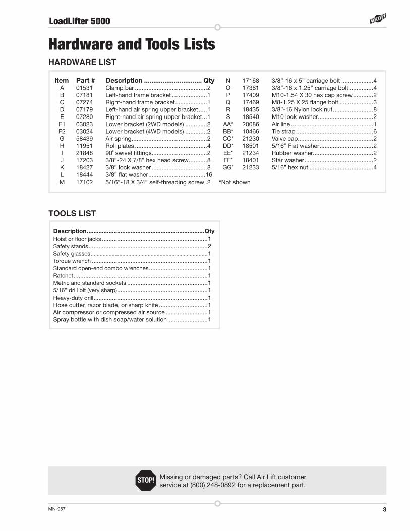
TOOLS LIST
Description . . . . . . . . . . . . . . . . . . . . . . . . . . . . . . . . . . . . . . . . . . . . . . . . . . . . . . . . . . . . . . . . . . . . . .QtyHoist or floor jacks . . . . . . . . . . . . . . . . . . . . . . . . . . . . . . . . . . . . . . . . . . . . . . . . . . . . . . . . . . . . . . .1Safety stands . . . . . . . . . . . . . . . . . . . . . . . . . . . . . . . . . . . . . . . . . . . . . . . . . . . . . . . . . . . . . . . . . . . . . . .2Safety glasses . . . . . . . . . . . . . . . . . . . . . . . . . . . . . . . . . . . . . . . . . . . . . . . . . . . . . . . . . . . . . . . . . . . . . . . . . . . . . .1Torque wrench . . . . . . . . . . . . . . . . . . . . . . . . . . . . . . . . . . . . . . . . . . . . . . . . . . . . . . . . . . . . . . . . . . . . .1Standard open-end combo wrenches . . . . . . . . . . . . . . . . . . . . . . . . . . . . . . . . . . .1Ratchet . . . . . . . . . . . . . . . . . . . . . . . . . . . . . . . . . . . . . . . . . . . . . . . . . . . . . . . . . . . . . . . . . . . . . . . . . . . . . . . .1Metric and standard sockets . . . . . . . . . . . . . . . . . . . . . . . . . . . . . . . . . . . . . . . . . . . . . . . .15/16” drill bit (very sharp) . . . . . . . . . . . . . . . . . . . . . . . . . . . . . . . . . . . . . . . . . . . . . . . . . . . . . .1Heavy-duty drill . . . . . . . . . . . . . . . . . . . . . . . . . . . . . . . . . . . . . . . . . . . . . . . . . . . . . . . . . . . . . . . . . . . .1Hose cutter, razor blade, or sharp knife . . . . . . . . . . . . . . . . . . . . . . . . . . . . .1Air compressor or compressed air source . . . . . . . . . . . . . . . . . . . . . . . . .1Spray bottle with dish soap/water solution . . . . . . . . . . . . . . . . . . . . . . . .1
Missing or damaged parts? Call Air Lift customer service at (800) 248-0892 for a replacement part .
STOP!
Item Part # Description . . . . . . . . . . . . . . . . . . . . . . . . . . . . . . . Qty A 01531 Clamp bar . . . . . . . . . . . . . . . . . . . . . . . . . . . . . . . . . . . . . . . . . . .2 B 07181 Left-hand frame bracket . . . . . . . . . . . . . . . . . . . . .1 C 07274 Right-hand frame bracket . . . . . . . . . . . . . . . . . . .1 D 07179 Left-hand air spring upper bracket . . . . .1 E 07280 Right-hand air spring upper bracket . . .1 F1 03023 Lower bracket (2WD models) . . . . . . . . . . . . .2 F2 03024 Lower bracket (4WD models) . . . . . . . . . . . . .2 G 58439 Air spring . . . . . . . . . . . . . . . . . . . . . . . . . . . . . . . . . . . . . . . . . . . . .2 H 11951 Roll plates . . . . . . . . . . . . . . . . . . . . . . . . . . . . . . . . . . . . . . . . . . .4 I 21848 90˚ swivel fittings . . . . . . . . . . . . . . . . . . . . . . . . . . . . . . . . .2 J 17203 3/8”-24 X 7/8” hex head screw . . . . . . . . . . .8 K 18427 3/8” lock washer . . . . . . . . . . . . . . . . . . . . . . . . . . . . . . . . .8 L 18444 3/8” flat washer . . . . . . . . . . . . . . . . . . . . . . . . . . . . . . . . . .16 M 17102 5/16”-18 X 3/4” self-threading screw .2
N 17168 3/8”-16 x 5” carriage bolt . . . . . . . . . . . . . . . . . . .4 O 17361 3/8”-16 x 1 .25” carriage bolt . . . . . . . . . . . . . .4 P 17409 M10-1 .54 X 30 hex cap screw . . . . . . . . . . . .2 Q 17469 M8-1 .25 X 25 flange bolt . . . . . . . . . . . . . . . . . . . .3 R 18435 3/8”-16 Nylon lock nut . . . . . . . . . . . . . . . . . . . . . . . .8 S 18540 M10 lock washer . . . . . . . . . . . . . . . . . . . . . . . . . . . . . . . . .2 AA* 20086 Air line . . . . . . . . . . . . . . . . . . . . . . . . . . . . . . . . . . . . . . . . . . . . . . . . .1 BB* 10466 Tie strap . . . . . . . . . . . . . . . . . . . . . . . . . . . . . . . . . . . . . . . . . . . . . .6 CC* 21230 Valve cap . . . . . . . . . . . . . . . . . . . . . . . . . . . . . . . . . . . . . . . . . . . . .2 DD* 18501 5/16” Flat washer . . . . . . . . . . . . . . . . . . . . . . . . . . . . . . . .2 EE* 21234 Rubber washer . . . . . . . . . . . . . . . . . . . . . . . . . . . . . . . . . . . .2 FF* 18401 Star washer . . . . . . . . . . . . . . . . . . . . . . . . . . . . . . . . . . . . . . . . .2 GG* 21233 5/16” hex nut . . . . . . . . . . . . . . . . . . . . . . . . . . . . . . . . . . . . . .4 *Not shown
HARDWARE LIST
Hardware and Tools Lists
LoadLifter 5000

MN-9574
IntroductionThe purpose of this publication is to assist with the installation, maintenance and troubleshooting of the LoadLifter 5000 air spring kit . LoadLifter 5000 utilizes sturdy, reinforced, commercial grade single or double, depending on the kit, convolute bellows . The bellows are manufactured like a tire with layers of rubber and cords that control growth . LoadLifter 5000 Ultimate kits are recommended for most 3/4- and 1-ton pickups and SUVs with leaf springs and provide up to 5,000 pounds of load leveling support with air adjustability from 5-100 PSI .
It is important to read and understand the entire installation guide before beginning installation or performing any maintenance, service or repair . The information here includes a hardware list, tool list, step-by-step installation information, maintenance guidelines and operating tips .
Air Lift Company reserves the right to make changes and improvements to its products and publications at any time . For the latest version of this manual, contact Air Lift Company at (800) 248-0892 or visit airliftcompany .com .
IMPORTANT SAFETY NOTICEThe installation of this kit does not alter the gross vehicle weight rating (GVWR) or payload of the vehicle . Check your vehicle’s owner’s manual and do not exceed the maximum load listed for your vehicle .
Gross vehicle weight rating: The maximum allowable weight of the fully loaded vehicle (including passengers and cargo) . This number — along with other weight limits, as well as tire, rim size and inflation pressure data — is shown on the vehicle’s Safety Compliance Certification Label .
Payload: The combined, maximum allowable weight of cargo and passengers that the truck is designed to carry . Payload is GVWR minus the base curb weight .
NOTATION EXPLANATIONHazard notations appear in various locations in this publication . Information which is highlighted by one of these notations must be observed to help minimize risk of personal injury or possible improper installation which may render the vehicle unsafe . Notes are used to help emphasize areas of procedural importance and provide helpful suggestions . The following definitions explain the use of these notations as they appear throughout this guide .
INDICATES IMMEDIATE HAZARDS WHICH WILL RESULT IN SEVERE PERSONAL INJURY OR DEATH .
INDICATES HAZARDS OR UNSAFE PRACTICES WHICH COULD RESULT IN SEVERE PERSONAL INJURY OR DEATH .
INDICATES HAZARDS OR UNSAFE PRACTICES WHICH COULD RESULT IN DAMAGE TO THE MACHINE OR MINOR PERSONAL INJURY .
Indicates a procedure, practice or hint which is important to highlight.
DANGER
CAUTION
WARNING
NOTE
LoadLifter 5000

MN-957 5
GETTING STARTED1 . Lift the vehicle up and support the frame with jack stands . Leave enough room to
drop the axle down low enough to install the air spring assemblies into position between the axle and the frame (fig . 2) .
2 . In order to install the assemblies, the jounce bumpers and cups will need to be removed (fig . 3) . Figure 4 shows the driver-side frame with the jounce bumper removed .
LoadLifter 5000
Installing the LoadLifter 5000 System
fig. 4
fig. 3
fig. 2

MN-9576
3 . Install the left-hand (driver-side) frame bracket (B) onto the frame, ensuring that the flange is on the inside of the frame . The large hole under the bracket will be behind the axle as shown (fig . 5) . Attach with the M10 hex cap screw (P) and lock washer (S), making sure that the bracket is parallel to the ridge that is under the frame rail . Torque to 35 lb .-ft . (47Nm) . Repeat for the right-hand (passenger) side .
4 . In order to install the lower brackets, remove the stock M8 hardware holding the brake/ABS and emergency brake line brackets to the spring perches (figs . 6 and 7) and pull the brackets slightly away from the spring perch .
The frame has a ridge; the bracket must be parallel to this ridge .
The large hole in the upper bracket will be behind the axle . The flange
on the bracket must be inboard of the frame .
Emergency brake cable forward of passenger side
LoadLifter 5000
S
P
fig. 7
fig. 6
fig. 5
MN-957 7
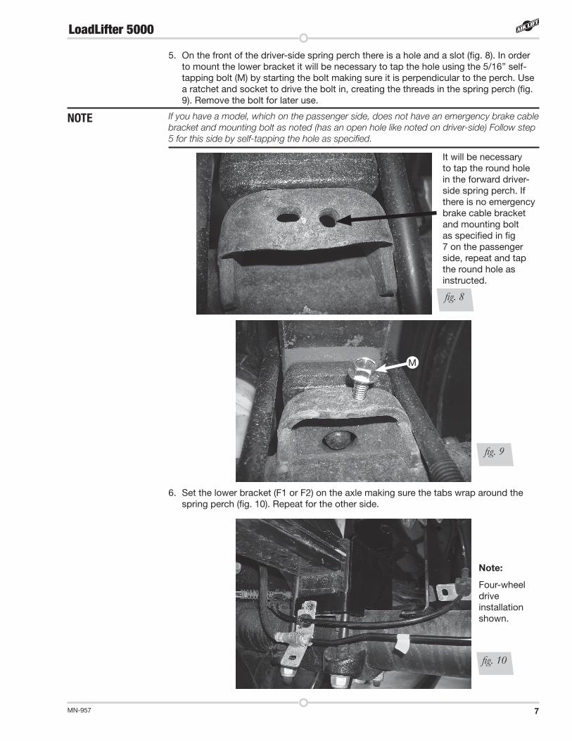
5 . On the front of the driver-side spring perch there is a hole and a slot (fig . 8) . In order to mount the lower bracket it will be necessary to tap the hole using the 5/16” self-tapping bolt (M) by starting the bolt making sure it is perpendicular to the perch . Use a ratchet and socket to drive the bolt in, creating the threads in the spring perch (fig . 9) . Remove the bolt for later use .
If you have a model, which on the passenger side, does not have an emergency brake cable bracket and mounting bolt as noted (has an open hole like noted on driver-side) Follow step 5 for this side by self-tapping the hole as specified.
6 . Set the lower bracket (F1 or F2) on the axle making sure the tabs wrap around the spring perch (fig . 10) . Repeat for the other side .
LoadLifter 5000
It will be necessary to tap the round hole in the forward driver-side spring perch . If there is no emergency brake cable bracket and mounting bolt as specified in fig 7 on the passenger side, repeat and tap the round hole as instructed .
Note:
Four-wheel drive installation shown .
M
fig. 8
fig. 9
fig. 10
NOTE

MN-9578
7 . Index the brake line/ABS bracket alignment tabs through the lower bracket on the back of the spring perch, and reattach using the M8 flange bolt (Q) provided (fig . 11) . Also, attach the emergency brake line bracket on the front of the passenger-side spring perch in the same manner . Finish by installing the 5/16” bolt previously used to tap the forward spring perch hole and LEAVE ALL HARDWARE LOOSE AT THIS TIME .
8 . For the 4WD models, insert the long 3/8” carriage bolts (N) through the lower bracket (fig . 12) .
Due to the tight clearance for the U-bolt to be positioned into place, it may be necessary to “rotate” or “screw” the carriage bolt into the square hole in the bracket.
Slide the clamp bar (A) over the carriage bolts and cap with a 3/8” flat washer (L) and nylon lock nut (R) (fig . 12) . Snug the nylon lock nuts down evenly until the clamp bar just makes contact with the axle . Leave loose at this time .
9 . For the 2WD models it will be necessary to invert the carriage bolt (run it upside down) (fig . 13) .
Note:
Four-wheel drive installation shown .
fig. 12
fig. 11
LoadLifter 5000
Q
N
A
L
R
NOTE
Note:
Two-wheel drive installation shown .
fig. 13
N
LR
A

MN-957 9
10 . Once the clamp bar is snug to the axle, torque all the spring perch hardware to 20 lb .-ft . (27Nm) . Then torque the axle clamp hardware to 15 lb .-ft . (20Nm) . Figures 14-17 (four-wheel drive) and 18-21 (two-wheel drive) show the lower bracket once it has been mounted to the axle .
Four-wheel drive models with lower bracket installed:
Two-wheel drive models with lower bracket installed:
LoadLifter 5000
Driver-side rear view Passenger-side rear view
Passenger-side front viewDriver-side front view
fig. 14 fig. 15
fig. 16 fig. 17
Driver-side rear view
Driver-side front view
Passenger-side rear view
Passenger-side front view
fig. 18 fig. 19
fig. 20 fig. 21
MN-95710
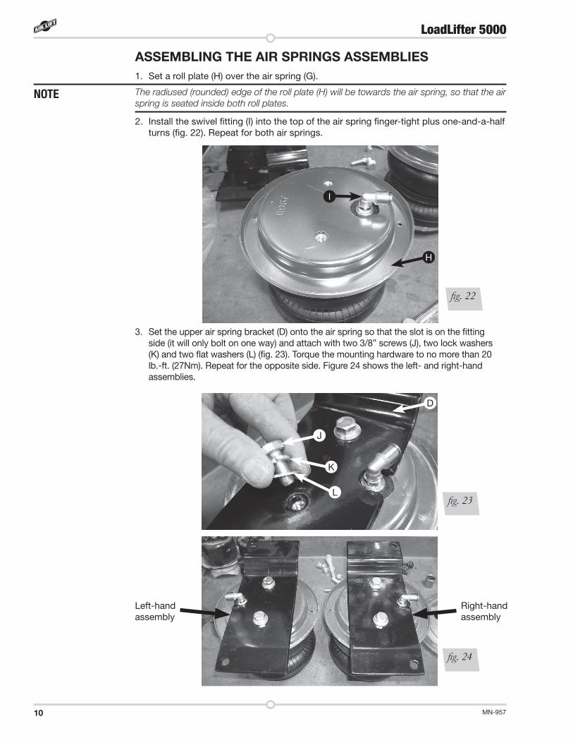
ASSEMBLING THE AIR SPRINGS ASSEMBLIES1 . Set a roll plate (H) over the air spring (G) .
The radiused (rounded) edge of the roll plate (H) will be towards the air spring, so that the air spring is seated inside both roll plates.
2 . Install the swivel fitting (I) into the top of the air spring finger-tight plus one-and-a-half turns (fig . 22) . Repeat for both air springs .
3 . Set the upper air spring bracket (D) onto the air spring so that the slot is on the fitting side (it will only bolt on one way) and attach with two 3/8” screws (J), two lock washers (K) and two flat washers (L) (fig . 23) . Torque the mounting hardware to no more than 20 lb .-ft . (27Nm) . Repeat for the opposite side . Figure 24 shows the left- and right-hand assemblies .
LoadLifter 5000
Left-hand assembly
Right-hand assembly
fig. 23
fig. 24
D
J
K
L
I
H
fig. 22
NOTE

MN-957 11
INSTALLING THE AIR SPRING ASSEMBLIES1 . With the axle dropped low enough to put the assemblies into position, set the left-
and right-hand assemblies on the lower brackets (previously installed), making sure that the fittings are on the outside of the frame as shown . Lift and attach the air spring upper bracket to the frame bracket using two 3/8” carriage bolts (O), two flat washers (L) and two nylon lock nuts (R) (figs . 25, 26) . Torque hardware to 20 lb .-ft . (27Nm) . Repeat for the opposite side .
2 . Set a roll plate in between the bellows and the lower bracket . Align the holes in the lower bracket and roll plate to the threaded inserts in the air spring (fig . 27) .
LoadLifter 5000
Driver-side (left) assembly shown .
NOTE: Fitting goes on the outside of the frame .
fig. 25
Slide the roll plate between the lower bracket and air spring while aligning the holes in all three .
fig. 27
fig. 26
O
L
R

MN-95712
3 . Raise the suspension back up just enough so that the air spring comes in contact with the roll plate and the lower bracket . Align the holes again and attach the lower air spring to the lower bracket using two 3/8” bolts (J), two lock washers (K) and flat washer (L) (fig . 28) . Repeat for the opposite side .
4 . Raise the axle all the way up and adjust the air spring by pushing it forward in the slot . Make sure it is aligned so that it is perpendicular to the upper and lower bracket . Torque the lower mounting bolts to no more than 20 lb .-ft . (27Nm) .
5 . Remove the jack stands .
6 . Figures 29, 30 and 31 show the finished installation of both left- and right-hand assemblies (four wheel models shown) .
Back view of left-side mounted assembly
Front view of left-side mounted assembly
fig. 29
fig. 30
LoadLifter 5000
Align the holes in the lower bracket and roll plate to the threaded insert in the air spring and attach with (L), (K) and (J) .
fig. 28
L
K
J

MN-957 13
Inside view of right-side mounted assembly
fig. 31
FINISHING THE INSTALLATION For 2WD models it will be necessary to trim the Brake/ABS line holder that is closest to the axle so that it does not chafe on the driver side bellows .
1 . Trim the outboard open slot on the plastic line holder off using a hack saw or side cutters (fig . 32) . Finished photo shown in fig . 33 .
fig. 32
fig. 33
Trim Brake/ABS line holder off here .
LoadLifter 5000

MN-95714
LoadLifter 5000
Installing the Air LinesThis section explains how to set up the air spring kit to be controlled with Schrader valves and a separate compressed air source . An on-board air compressor system allows for hassle-free control of the air springs . Learn more about Air Lift control systems at www .airliftcompany .com/products/compressor-systems .
1 . Choose a convenient location for mounting the inflation valves (fig . 34) . Popular locations for the inflation valve are:
a . The wheel well flanges
b . The license plate recess in bumper
c . Under the gas cap access door
d . Through the license plate
NOTE Whatever the chosen location, make sure there is enough clearance around the inflation valves for an air chuck.
2 . Drill 5/16” holes to install the inflation valves .
3 . Cut the air line assembly in two equal lengths .
4 . Place a 5/16” nut and star washer on the air valve . Leave enough of the inflation valve in front of the nut to extend through the hole and have room for the rubber washer, flat washer, and 5/16” nut and cap . There should be enough valve exposed after installation – approximately 1/2” – to easily apply a pressure gauge or an air chuck (fig . 35) .
5 . Push the inflation valve through the hole and use the rubber washer, flat washer, and another 5/16” nut to secure it in place . Tighten the nuts to secure the assembly .
6 . Route the air line along the frame to the fitting on the air spring . Keep AT LEAST 6” of clearance between the air line and the exhaust system . Avoid sharp bends and edges . Use zip ties to secure the air line to fixed points along the chassis . Be sure that the tie straps are tight, but do not pinch the air line . Leave at least 2” of slack to allow for any movement that might pull on the air line .
7 . Cut off the air line, leaving approximately 12” of extra air line . A clean square cut will prevent leaks . Insert the air line into the air fitting . This is a push-to-connect fitting .
Wiggle the hose back and forth while inserting to make sure the hose bottoms out in the fitting to obtain a good seal.
TECH TIP
Option 1:Option 2:
fig. 34
Air line toair spring
Starwasher
Vehicle bodyor bumper
Hex nut
Hex nut
Rubberwasher
Flatwasher
ValveCap
Schrader valve
fig. 35

MN-957 15
LoadLifter 5000
INSTALLING THE HEAT SHIELD1 . Bend tabs to provide a dead air space between exhaust pipe and heat shield . (Fig . 37)
Attach the heat shield to the exhaust pipe using the clamps . Bend the heat shield for maximum clearance to the air spring .
Some vehicles have large resonators in this area; it will be necessary to double up on the clamps to fit these models (fig. 37).
NOTE
fig. 36
TIPS FOR INSTALLING AIR LINESWhen cutting air lines, use a sharp knife or a hose cutter and make clean, square cuts (fig . 36) . Do not use scissors or wire cutters because these tools may deform the air line, causing it to leak around fittings . Do not cut the lines at an angle .
Do not bend the 1/4” hose at a radius of less than 1” or bend the 3/8” hose at a radius of less than 1 1/2” . Do not put side load pressure on fitting . The hose should be straight beyond the fitting for 1” before bending .
Inspect hose for scratches that run lengthwise on hose prior to installation . Contact Air Lift customer service at (800) 248-0892 if the air line is damaged .
Go to air-lift .co/cuttingairline to watch a video demonstrating proper air line cutting .
fig. 37
Exhaust resonator
Double up supplied hose clamps provided
1/2” dead air space
Bend tabs

MN-95716
LoadLifter 5000
CHECKING FOR LEAKS
1 . Inflate the air spring to 30 PSI .
2 . Spray all connections and the inflation valves with a solution of 1/5 liquid dish soap and 4/5 water . Spot leaks easily by looking for bubbles in the soapy water .
3 . After the test, deflate the springs to the minimum pressure required to restore the system to normal ride height . Do not deflate to lower than 5 PSI .
4 . Check the air pressure again after 24 hours . A 2-4 PSI loss after initial installation is normal . Retest for leaks if the loss is more than 5 PSI .
FIXING LEAKS1 . If there is a problem with the swivel fitting:
a . Check the air line connection by deflating the spring and removing the line by pulling the collar against the fitting and pulling firmly on the air line . Trim 1” off the end of the air line . Be sure the cut is clean and square (see Fig . 36) . Reinsert the air line into the push-to-connect fitting .
b . Check the threaded connection by tightening the swivel fitting another half turn . If it still leaks, deflate the air spring, remove the fitting, and re-coat the threads with thread sealant . Reinstall by hand tightening as much as possible and then use a wrench for an additional two turns .
2 . If there is a problem with the inflation valve:a . Check the valve core by tightening it with a valve core tool .b . Check the air line by removing the air line from the barbed type fitting . Cut the
air line off a few inches in front of the fitting and use a pair of pliers or vice grips to pull/twist the air line off of the fitting .
DO NOT CUT OFF THE AIR LINE COMPLETELY AS THIS WILL USUALLY NICK THE BARB AND RENDER THE FITTING USELESS .
3 . If the preceding steps have not resolved the problem, call Air Lift customer service at (800) 248-0892 .
Before Operating
CAUTIONCAUTION

MN-957 17
LoadLifter 5000
Clearance test — Inflate the air springs to 75-90 PSI and make sure there is at least 1/2” clearance from anything that might rub against each sleeve . Be sure to check the tire, brakes, frame, shock absorbers and brake cables .
Leak test before road test — Inflate the air springs to 75-90 PSI and check all connections for leaks . All leaks must be eliminated before the vehicle is road tested .
Heat test — Be sure there is sufficient clearance from heat sources, at least 6” for air springs and air lines . If a heat shield was included in the kit, install it . If there is no heat shield, but one is required, call Air Lift customer service at (800) 248-0892 .
Fastener test — Recheck all bolts for proper torque .
Road test — The vehicle should be road tested after the preceding tests . Inflate the springs to recommended driving pressures . Drive the vehicle 10 miles and recheck for clearance, loose fasteners and air leaks .
Operating instructions — If professionally installed, the installer should review the operating instructions with the owner . Be sure to provide the owner with all of the paperwork that came with the kit .
Overnight leak down test — Recheck air pressure after the vehicle has been used for 24 hours . If the pressure has dropped more than 5 PSI, then there is a leak that must be fixed . Either fix the leak yourself or return to the installer for service .
Air pressure requirements — It is important to understand the air pressure requirements of the air spring system . Regardless of load, the air pressure should always be adjusted to maintain adequate ride height at all times while driving .
Thirty-day or 500-mile test —Recheck the air spring system after 30 days or 500 miles, whichever comes first . If any part shows signs of rubbing or abrasion, the source should be identified and moved, if possible . If it is not possible to relocate the cause of the abrasion, the air spring may need to be remounted . If professionally installed, the installer should be consulted . Check all fasteners for tightness .
POST-INSTALLATION CHECKLIST
INSTALLATION CHECKLIST

MN-95718
LoadLifter 5000
MAINTENANCE GUIDELINESBy following the steps below, vehicle owners will obtain the longest life and best results from their air springs.
1 . Check air pressure weekly .
2 . Always maintain normal ride height . Never inflate beyond 100 PSI .
3 . If the system develops an air leak, use a soapy water solution (1/5 liquid dish soap and 4/5 water) to check all air line connections and the inflation valve core before deflating and removing the air spring .
FOR SAFETY AND TO PREVENT POSSIBLE DAMAGE TO THE VEHICLE, DO NOT EXCEED MAXIMUM GROSS VEHICLE WEIGHT RATING (GVWR), AS INDICATED BY THE VEHICLE MANUFACTURER . ALTHOUGH THE AIR SPRINGS ARE RATED AT A MAXIMUM INFLATION PRESSURE OF 100 PSI, THE AIR PRESSURE ACTUALLY NEEDED IS DEPENDENT ON LOAD AND GVWR .
4 . Loaded vehicles require at least 25 PSI . A “loaded vehicle” refers to a vehicle with a heavy bed load, a trailer or both . Never exceed GVWR, regardless of air spring, air pressure or other load assist . The springs in this kit will support approximately 40 pounds of load (combined on both springs) for each 1 PSI of pressure . The required air pressure will vary depending on the state of the original suspension . Operating the vehicle below the minimum air spring pressure will void the Air Lift warranty .
5 . When increasing load, always adjust air pressure to maintain normal ride height . Increase or decrease pressure from the system as necessary to attain normal ride height for optimal ride and handling . Remember that loads carried behind the axle (including tongue loads) require more leveling force (pressure) than those carried directly over the axle .
6 . Always add air to springs in small quantities, checking the pressure frequently .
7 . Should it become necessary to raise the vehicle by the frame, make sure the system is at minimum pressure (5 PSI) to reduce the tension on the suspension/brake components . Use of on-board leveling systems do not require deflation or disconnection .
8 . Periodically check the air spring system fasteners for tightness . Also, check the air springs for any signs of rubbing . Realign if necessary .
9 . On occasion, give the air springs a hard spray with a garden hose to remove mud, sand, gravel or other debris .
NOTE
Product Use, Maintenance and Servicing
5 PSI 100 PSI
Maximum Air PressureMinimum Recommended Pressure
CAUTIONCAUTION

MN-957 19
LoadLifter 5000
TUNING THE AIR PRESSUREPressure determination comes down to three things — level vehicle, ride comfort and stability .
1 . Level vehicle
If the vehicle’s headlights are shining into the trees or the vehicle is leaning to one side, then it is not level (fig . 38) . Raise the air pressure to correct either of these problems and level the vehicle .
2 . Ride comfort
If the vehicle has a rough or harsh ride it may be due to either too much pressure or not enough (fig . 39) . Try different pressures to determine the best ride comfort .
3 . Stability
Stability translates into safety and should be the priority, meaning the driver may need to sacrifice a perfectly level and comfortable ride . Stability issues include roll control, bounce, dive during braking and sponginess (fig . 40) . Tuning out these problems usually requires an increase in pressure .
GUIDELINES FOR ADDING AIR1 . Start with the vehicle level or slightly above .
2 . When in doubt, always add air .
3 . If the front of the vehicle dives while braking, increase the pressure in the front air bags, if equipped .
4 . If it is ever suspected that the air bags have bottomed out, increase the pressure (fig . 41) .
5 . Adjust the pressure up and down to find the best ride .
6 . If the vehicle rocks and rolls, adjust the air pressure to reduce movement .
7 . It may be necessary to maintain different pressures on each side of the vehicle . Loads such as water, fuel, and appliances will cause the vehicle to be heavier on one side (fig . 42) . As much as a 50 PSI difference is not uncommon .
Bad headlight aimSway and body roll
Rough ridefig. 38 fig. 40fig. 39
Bottoming out Unlevel Level
fig. 41 fig. 42

MN-95720
LoadLifter 5000
Troubleshooting GuidePROBLEM CAUSE SOLUTION
System won’t maintain pressure overnight .
Improperly installed air line, air line has holes or cracks .
Leak test the air line connections, the threaded connection into the air spring, and all fittings in the control system .
Air spring or air line leak . Fitting seal or air line is compromised . Check to make sure air lines are seated in connectors . Inspect fittings with soapy water . Trim hose or re-seal fitting . Ensure lines are cut straight .
Corner won't raise or air leak develops .
Look for a kink or fold in the air line . Replace any air line that has been kinked .
FREQUENTLY ASKED QUESTIONSQ . Will installing air springs increase the weight ratings of a vehicle?
No . Adding air springs will not change the weight ratings (GAWR, GCWR and/or GVWR) of a vehicle . Exceeding the GVWR is dangerous and voids the Air Lift warranty .
Q . Is it necessary to keep air in the air springs at all times and how much pressure will they need?
For LoadLifter 5000, the recommended minimum air pressure is 5 PSI, but it can safely be run at zero air pressure unladen (no load) .
Q . Is it necessary to add a compressor system to the air springs?
No . Air pressure can be adjusted with any type of compressor as long as it can produce sufficient pressure to service the springs . Even a bicycle tire pump can be used, but it’s a lot of work .
Q . How long should air springs last?
If the air springs are properly installed and maintained they can last indefinitely .
Q . Will raising the vehicle on a hoist for service work damage the air springs?
No . The vehicle can be lifted on a hoist for short-term service work such as tire rotation or oil changes . However, if the vehicle will be on the hoist for a prolonged period of time, support the axle with jack stands in order to take the tension off of the air springs .

MN-957 21
LoadLifter 5000
Replacement Part InformationIf replacement parts are needed, contact the local dealer or call Air Lift customer service at (800) 248-0892 . Most parts are immediately available and can be shipped the same day .
Contact Air Lift Company customer service at (800) 248-0892 first if:• Parts are missing from the kit .• Need technical assistance on installation or operation .• Broken or defective parts in the kit .• Wrong parts in the kit .• Have a warranty claim or question .
Contact the retailer where the kit was purchased:• If it is necessary to return or exchange the kit for any reason .• If there is a problem with shipping if shipped from the retailer .• If there is a problem with the price .
Contact InformationMailing address P .O . Box 80167 Lansing, MI 48908-0167
Shipping address 2727 Snow Road for returns Lansing, MI 48917
Phone Toll free: (800) 248-0892 International: (517) 322-2144
Email service@airliftcompany .com
Web address www .airliftcompany .com
Limited Warranty and Return PolicyAir Lift Company provides a limited lifetime warranty to the original purchaser of its Load Support products, that the products will be free from defects in workmanship and materials when used on cars and trucks as specified by Air Lift Company and under normal operating conditions, subject to the requirements and exclusions set forth in the full Limited Warranty and Return Policy that is available online at www .airliftcompany .com/warranty .
For additional warranty information contact Air Lift Company customer service .

Need Help?Contact Air Lift Company customer service department by calling (800) 248-0892 . For calls from outside the USA or Canada, dial (517) 322-2144 .
Need Help?Contact Air Lift Company customer service department by calling (800) 248-0892 . For calls from outside the USA or Canada, dial (517) 322-2144 .
Air Lift Company • 2727 Snow Road • Lansing, MI 48917 or P .O . Box 80167 • Lansing, MI 48908-0167 Toll Free (800) 248-0892 • Local (517) 322-2144 • Fax (517) 322-0240 • www .airliftcompany .com
Thank you for purchasing Air Lift products — the professional installer’s choice!
Printed in the USA BGL-1216